Embed Size (px)
Citation preview

781
ACTA UNIVERSITATIS AGRICULTURAE ET SILVICULTURAE MENDELIANAE BRUNENSIS
Volume 64 89 Number 3, 2016
http://dx.doi.org/10.11118/actaun201664030781
LABORATORY INVESTIGATION OF THE EFFECT OF THE SIZE OF ORIFICE ON THE PERFORMANCE OF CURVATURE
SUBMERGE VANES FOR SEDIMENT LEACHING OF THE VORTEX SETTLING BASIN’S FLOOR
Amin Hajiahmadi1,Mohammad J. Khanjani1, Mojtaba Saneie2, Mehdi Azhdari Moghaddam3
1 Department of Civil Engineering, University of Shahid Bahonar, Kerman, Iran2 Soil Conservation and Watershed Management Research Institute (SCWMRI), Tehran, Iran3 Department of Civil Engineering, University of Sistan and Baluchestan, Zahedan, Iran
Abstract
HAJIAHMADI AMIN, KHANJANI MOHAMMAD J., SANEIE MOJTABA, MOGHADDAM MEHDI AZHDARI. 2016. Laboratory Investigation of the Eff ect of the Size of Orifi ce on the Performance of Curvature Submerge Vanes for Sediment Leaching of the Vortex Settling Basin’s Floor. Acta Universitatis Agriculturae et Silviculturae Mendelianae Brunensis, 64(3): 781–789.
In this paper, considering the accumulation of the sediments on the fl oor of the vortex settling basin during sediment extracting, curvature submerge vanes were used on the fl oor of the vortex basin and the eff ect of the size of the orifi ce was studied on the performance of the curvature submerge vanes for sediment leaching of the fl oor of the basin. Experiments were performed on a physical model with a height of 90 cm and a diameter of 206 cm and a fl oor slope of 10% and also three orifi ces were used with diameters of 59, 46 and 36 mm. The submerge vanes were placed in diff erent arrangements and diff erent radial sections. The results of the experiments indicated that the performance of the vanes in sediment extracting on the fl oor is primarily infl uenced by the orifi ce and secondly by the arrangements and radial sections of the vanes’ placements.
Keywords: Curvature submerge vanes, effi ciency, orifi ce, sediment, vortex settling basin
INTRODUCTIONThe issue of controlling the sediments present
in the fl ows is an issue which has always been considered in the application of the river fl ows. Because the natural fl ows always transfer some sediment with them according to the conditions aff ecting the fl ow and the characteristics of the waterway bed, due to fl owing to the non-rigid soil bed.
Lack of control over the sedimentation entrance to the intakes leads to their transmission into the irrigation canals and installations, and causes a lot of diffi culties as the result of carrying the sediments or their deposition in various parts. In case the fl ow rate is high, the tiny particles suspended in the water cause a lot of damage to the facilities, especially in
the cases where the mechanical devices such as pumps and turbines are used. Among the problems related to lack of control of the sediments in the intakes, the following cases can be noted: a) Reduction of the transfer capacity of the canals in
case of sediment deposition. b) Erosion and devastation of the canal walls in case
of presence of the coarse material. c) Disruption of water supply to farms due to water
cut off for dredging the canals. d) High costs of canal dredging.
Therefore we need to solve the issue of thepresence of sediments for application of the water from natural streams. There are various methods for solving the issue of the presence of sediments in the intakes. Vortex settling basins are also one of

782 Amin Hajiahmadi, Mohammad J. Khanjani, Mojtaba Saneie, Mehdi Azhdari Moghaddam
the structures used to control the sediments in water networks by the use of this quality of the vortex fl ow.
Vortex settling basins is used for removing the sediments from the intakes, especially the small grain and suspended particles. The demand for this type of sediment extractor is increasing, because this method is more economical and in smaller sizes than the traditional methods such as settling basins. It also helps save water.
This type of sediment extractor uses the vortex fl ow to remove the sediments from the water fl ow. The fl ow of water enters the cylindrical basin which has a central orifi ce in its fl oor, tangentially and with high speed. The tangential and high speed fl ow into the cylinder creates a vortex. This fi eld of vortex fl ows created in these basins is usually of the Rankin vortex type (Athar, 2002).
Formation of Rankin vortex, causes increase sediment concentration to outward. On the other hand, centrifugal force of vortex, conduct the sediment movement to vortexes walls. A� er that the secondary fl ow inside the vortex (because of fl ow orifi ce suction), motivates this movement to the central orifi ce in the basin bottom (Ghafari, 2000).
In general, the secondary fl ows in such systems are created as the result of the following factors: a) Reduction of the marginal speed of the fl uid due
to the friction between the fl oor of the basin and the fl uid.
b) The fl ow perpendicular to the vortex fl ow towardthe center of the basin.
c) The eruptive inlet fl ow and the side overfl owsand the centrifugal force of the basin’s vortex.
For the maximum length of the rotation, the basin should be constructed tangent to the input channel. The secondary fl ows lead those layers of the fl ow which are close to the fl oor, toward the central orifi ce. Thus, the sediment particles that are heavier than the fl uid move toward the orifi ce by travelling through a spiral path and enter the discharge tube. The discharge tube is connected to the discharge canal and that is connected to the river and by this means the sediments are extracted from the water (Fig. 1).
A core of air is formed in the center of the orifi ce, the dimensions of this core depend on the size of the orifi ce, also this core of air reduces the output discharge from the central orifi ce and increases the hydraulic effi ciency of the basin.
Many researchers have worked on these basins to increase its effi ciency. For instance Ogihara and Sakaguchi (1984) used the tulip spillway for transferring the clear water in their investigation instead of lateral spillway. Mashauri (1986) conducted his experiments on three models with diff erent scales. Paul (1991) introduced a design that a horseshoe-formed vane (defl ector) was used which was installed in the input channel at a distance of a third of the depth of the fl ow. Athar et al. (2002) presented two other models of vortex settling basin.
Deposition of a percentage of the sediments on the fl oor of the basin and no withdrawal from the fl ushing orifi ce are one of the major problems of these types of basins. This problem that may be due to some reasons such as lack of an appropriate designation or any other factor will cause dysfunction of the basin over time. This issue has caused a necessity for conducting the essential studies and research to provide a method for withdrawal or reduction of these sediments.
Diff erent researchers have investigated diff erent approaches to resolving the problem of deposition of the sediments on the fl oor of these basins. Researchers at Istanbul Technical University (IUT) such as Cecen and Akmandor (1973), Curiet et al. (1979) and Cecen and Bayazit (1975) concluded in their studies that making a dip in the basin’s fl oor helps to drain the sediments from the fl oor of the basin. Paul et al. (1991) and Ziaei (2000) presented a model with two inputs for the basin and changing the fl ow from clockwise to counter clockwise and vice versa for sediment leaching of the basin’s fl oor.
In the present study the eff ect of the size of the orifi ce was investigated in the laboratory on the performance of curved submerge vanes during sediment leaching of the basin’s fl oor. In this project, by planting the curvature submerge vanes on the fl oor of the basin, the secondary fl ows formed by these vanes are reinforced, and also the vortex fl ow within the basin is modifi ed and thus it leads to easy movement of the fl oor sediments toward the fl ushing orifi ce. Now in this study, the eff ect of changes in the orifi ce size was investigated on the performance rate of curvature submerge vanes.
EXPERIMENTAL EQUIPMENTS
Experimental ModelLaboratory experiments on the physical model
of vortex settling basin were conducted in the Soil Conservation and Watershed Management Research Institute. In Fig. 2 the plan of the laboratory model is
1: The spiral path and the secondary flow formed in the basin
Laboratory Investigation of the Eff ect of the Size of Orifi ce on the Performance of Curvature Submerge Vanes… 783
indicated and the components are mentioned and in Tab. I the model specifi cations are shown.
Also in this basin, a defl ector is embedded horizontally and fl at below the spillway and a diaphragm is embedded in the inlet. The defl ector structure is embedded to prevent the exit of sediment particles on arrival to the basin under the infl uence of the outfl ow jet of the spillway, which increases the residence time of the sediment containing fl ow in the basin, and ultimately the sediments will spin more.
According the previous studies by researchers such as Cecen and Bayazit (1975) and Mashauri (1986), optimum fl oor slope is considered 10%. It is content that increasing the slop, would Reduction of the sediments in the fl oor basin but in return increased the output discharge from the central orifi ce and reduces the effi ciency of the basin.
Sediment InjectionIn this study, materials with a uniform grain size
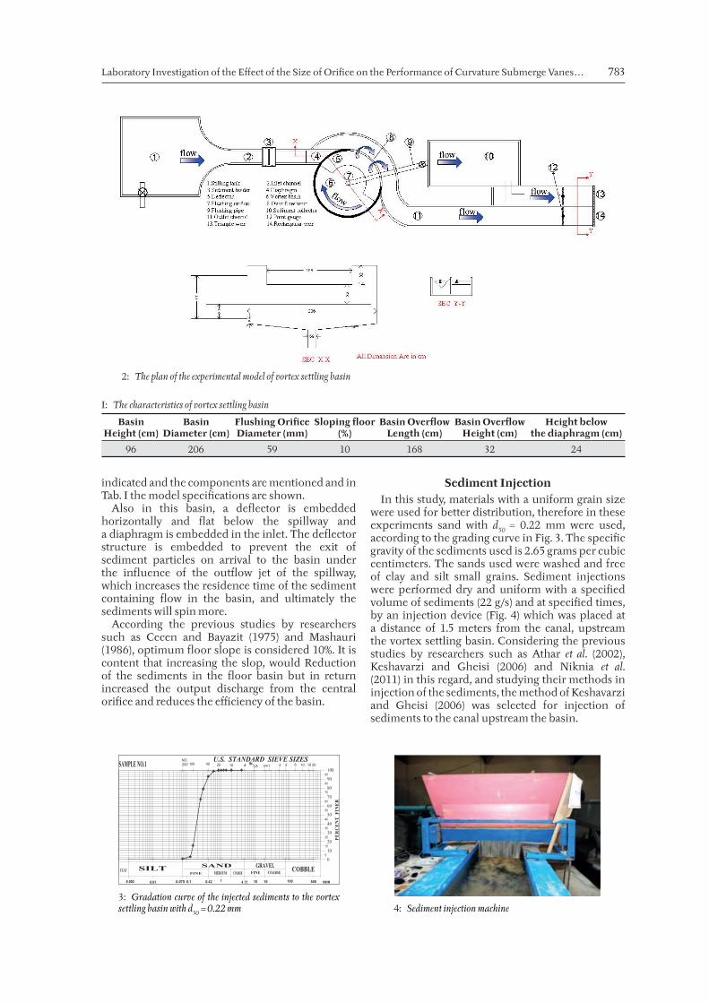
were used for better distribution, therefore in these experiments sand with d50 = 0.22 mm were used, according to the grading curve in Fig. 3. The specifi c gravity of the sediments used is 2.65 grams per cubic centimeters. The sands used were washed and free of clay and silt small grains. Sediment injections were performed dry and uniform with a specifi ed volume of sediments (22 g/s) and at specifi ed times, by an injection device (Fig. 4) which was placed at a distance of 1.5 meters from the canal, upstream the vortex settling basin. Considering the previous studies by researchers such as Athar et al. (2002), Keshavarzi and Gheisi (2006) and Niknia et al. (2011) in this regard, and studying their methods in injection of the sediments, the method of Keshavarzi and Gheisi (2006) was selected for injection of sediments to the canal upstream the basin.
2: The plan of the experimental model of vortex settling basin
I: The characteristics of vortex settling basin
Basin Height (cm)
Basin Diameter (cm)
Flushing Orifi ce Diameter (mm)
Sloping fl oor (%)
Basin Overfl ow Length (cm)
Basin Overfl ow Height (cm)
Height below the diaphragm (cm)
96 206 59 10 168 32 24
U.S. STANDARD SIEVE SIZES
3: Gradation curve of the injected sediments to the vortex settling basin with d50 = 0.22 mm 4: Sediment injection machine
784 Amin Hajiahmadi, Mohammad J. Khanjani, Mojtaba Saneie, Mehdi Azhdari Moghaddam
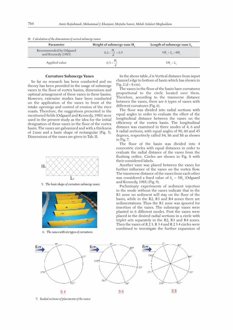
Curvature Submerge VanesSo far no research has been conducted and no
theory has been provided in the usage of submerge vanes in the fl oor of vortex basins, dimensions and optimal arrangement of these vanes in these basins. However, extensive studies have been conducted on the application of the vanes in front of the intake openings and control of erosion of the river coasts. Therefore, the suggestions presented in the mentioned fi elds (Odgaard and Kennedy, 1983) were used in the present study as the idea for the initial designation of these vanes in the fl oor of the vortex basin. The vanes are galvanized and with a thickness of 2 mm and a basic shape of rectangular (Fig. 5). Dimensions of the vanes are given in Tab. II.
In the above table, d is Vertical distance from input channel edge to bottom of basin which has shown in Fig. 2 (d = 8 cm).
The vanes in the fl oor of the basin have curvatures proportional to the circle located over them. Therefore, according to the transverse distance between the vanes, there are 6 types of vanes with diff erent curvatures (Fig. 6).
The fl oor was divided into radial sections with equal angles in order to evaluate the eff ect of the longitudinal distance between the vanes on the effi ciency of the vortex basin. The longitudinal distance was examined in three modes of 4, 6 and 8 radial sections, with equal angles of 90, 60 and 45 degrees, respectively called S4, S6 and S8 as shown in Fig. 7.
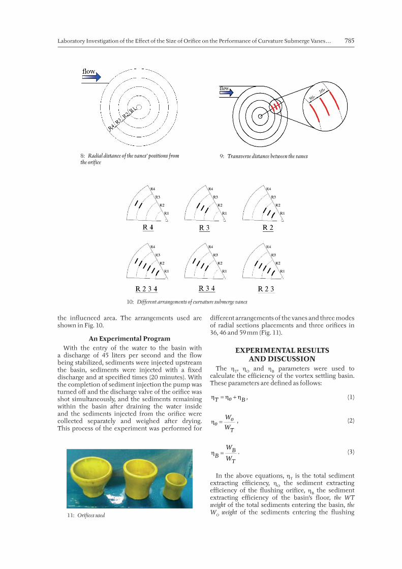
The fl oor of the basin was divided into 4 concentric circles with equal distances in order to evaluate the radial distance of the vanes from the fl ushing orifi ce. Circles are shown in Fig. 8 with their considered labels.
Another vane was placed between the vanes for further infl uence of the vanes on the vortex fl ow. The transverse distance of the vanes from each other was considered a fi xed value of n = 3Hv (Odgaardand Kennedy, 1983) (Fig. 9).
Preliminary experiments of sediment injection in the mode without the vanes indicate that in the R1 zone no sediment will stay on the fl oor of the basin, while in the R2, R3 and R4 zones there are sedimentations. Thus the R1 zone was ignored for insertion of the vanes. The submerge vanes were planted in 6 diff erent modes. First the vanes were placed in the desired radial sections in a circle with triplet sets separately in the R2, R3 and R4 zones. Then the vanes of R 2 3, R 3 4 and R 2 3 4 circles were combined to investigate the further expansion of
II: Calculation of the dimensions of curved submerge vanes
Parameter Height of submerge vane Hv Length of submerge vane Lv
Recommended by Odgaard and Kennedy (1983)
Hv 0.2 < < 0.5
d 3Hv < Lv <4Hv
Applied valueHv
0.5 = d
3Hv = Lv
5: The basic shape of curvature submerge vanes
6: The vanes with six types of curvatures
7: Radial sections of placements of the vanes
Laboratory Investigation of the Eff ect of the Size of Orifi ce on the Performance of Curvature Submerge Vanes… 785
the infl uenced area. The arrangements used are shown in Fig. 10.
An Experimental ProgramWith the entry of the water to the basin with
a discharge of 45 liters per second and the fl ow being stabilized, sediments were injected upstream the basin, sediments were injected with a fi xed discharge and at specifi ed times (20 minutes). With the completion of sediment injection the pump was turned off and the discharge valve of the orifi ce was shot simultaneously, and the sediments remaining within the basin a� er draining the water inside and the sediments injected from the orifi ce were collected separately and weighed a� er drying. This process of the experiment was performed for
diff erent arrangements of the vanes and three modes of radial sections placements and three orifi ces in 36, 46 and 59 mm (Fig. 11).
EXPERIMENTAL RESULTS AND DISCUSSION
The T, O and B parameters were used tocalculate the effi ciency of the vortex settling basin. These parameters are defi ned as follows:
T Bo , (1)
T
Woo
W , (2)
BB
T
W
W . (3)
In the above equations, T is the total sedimentextracting effi ciency, O the sediment extractingeffi ciency of the fl ushing orifi ce, B the sedimentextracting effi ciency of the basin’s fl oor, the WT weight of the total sediments entering the basin, the WO weight of the sediments entering the fl ushing
8: Radial distance of the vanes’ positions from the orifice
9: Transverse distance between the vanes
10: Different arrangements of curvature submerge vanes
11: Orifices used
786 Amin Hajiahmadi, Mohammad J. Khanjani, Mojtaba Saneie, Mehdi Azhdari Moghaddam
orifi ce, the WB weight of the sediments of the basin’s fl oor. Also the G’ parameter is used to show the sediment extracting rate of the fl oor:
( )'
'B B
B
G
. (4)
In equation 4, G’ is the effi ciency of sediment leaching from the fl oor, B the effi ciency of sedimentextracting of the basin’s fl oor without curvature submerge vanes and ’B the effi ciency of sedimentextracting of the basin’s fl oor with curvature submerge vanes.
Also Q0/Qt is used to show the rate of basin’s discharge loss in diff erent modes where Q0 is the output discharge of the fl ushing orifi ce and Qt the total discharge entering the basin.
For a simpler evaluation of the eff ects of each of the variables, initially in the fi rst stage appropriate arrangements were selected for one size of the fl ushing orifi ce and a constant discharge entering the basin and in the second stage the eff ect of the orifi ce was studied on the performance of the curvature submerge vanes in the vortex settling basin.
The First StageAt this stage of the experiments, the eff ect of the
vanes on the defi ned parameters was assessed with the placement of the vanes in three radial section modes of (S4, S6 and S8) and six arrangements of (R2, R3, R4, R2 3, R3 4 and R2 3 4). To get started, an orifi ce with a diameter of 59 mm and a maximum input discharge of 45 l/s was used.
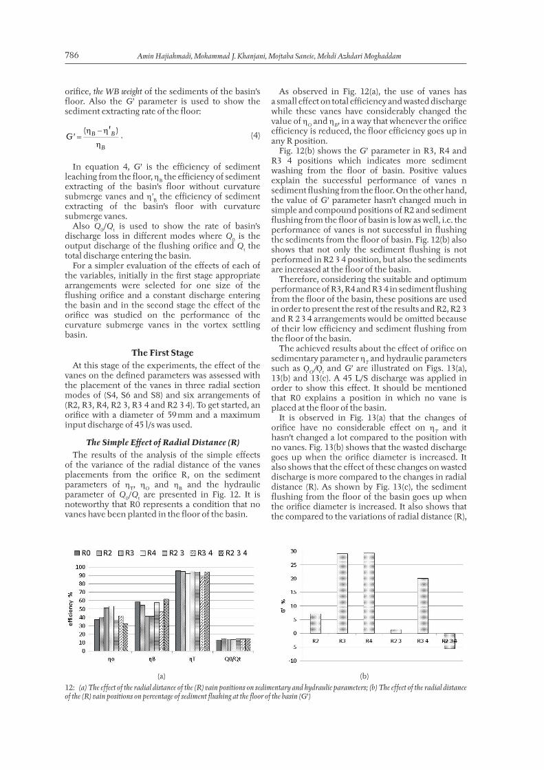
The Simple Eff ect of Radial Distance (R)The results of the analysis of the simple eff ects
of the variance of the radial distance of the vanes placements from the orifi ce R, on the sediment parameters of T, O and B and the hydraulicparameter of Q0/Qt are presented in Fig. 12. It is noteworthy that R0 represents a condition that no vanes have been planted in the fl oor of the basin.
As observed in Fig. 12(a), the use of vanes has a small eff ect on total effi ciency and wasted discharge while these vanes have considerably changed the value of O and B, in a way that whenever the orifi ceeffi ciency is reduced, the fl oor effi ciency goes up in any R position.
Fig. 12(b) shows the G’ parameter in R3, R4 and R3 4 positions which indicates more sediment washing from the fl oor of basin. Positive values explain the successful performance of vanes n sediment fl ushing from the fl oor. On the other hand, the value of G’ parameter hasn’t changed much in simple and compound positions of R2 and sediment fl ushing from the fl oor of basin is low as well, i.e. the performance of vanes is not successful in fl ushing the sediments from the fl oor of basin. Fig. 12(b) also shows that not only the sediment fl ushing is not performed in R2 3 4 position, but also the sediments are increased at the fl oor of the basin.
Therefore, considering the suitable and optimum performance of R3, R4 and R3 4 in sediment fl ushing from the fl oor of the basin, these positions are used in order to present the rest of the results and R2, R2 3 and R 2 3 4 arrangements would be omitted because of their low effi ciency and sediment fl ushing from the fl oor of the basin.
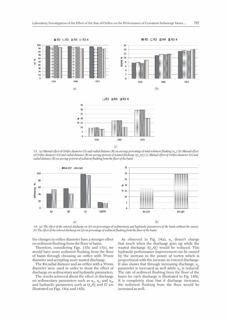
The achieved results about the eff ect of orifi ce on sedimentary parameter T and hydraulic parameters such as ǪO/Ǫt and G’ are illustrated on Figs. 13(a),13(b) and 13(c). A 45 L/S discharge was applied in order to show this eff ect. It should be mentioned that R0 explains a position in which no vane is placed at the fl oor of the basin.
It is observed in Fig. 13(a) that the changes of orifi ce have no considerable eff ect on T and ithasn’t changed a lot compared to the position with no vanes. Fig. 13(b) shows that the wasted discharge goes up when the orifi ce diameter is increased. It also shows that the eff ect of these changes on wasted discharge is more compared to the changes in radial distance (R). As shown by Fig. 13(c), the sediment fl ushing from the fl oor of the basin goes up when the orifi ce diameter is increased. It also shows that the compared to the variations of radial distance (R),
(a) (b)
12: (a) The effect of the radial distance of the (R) vain positions on sedimentary and hydraulic parameters; (b) The effect of the radial distance of the (R) vain positions on percentage of sediment flushing at the floor of the basin (G’)
Laboratory Investigation of the Eff ect of the Size of Orifi ce on the Performance of Curvature Submerge Vanes… 787
the changes in orifi ce diameter have a stronger eff ect on sediment fl ushing from the fl oor of basin.
Therefore, considering Figs. 13(b) and 13(c), we would have more sediment fl ushing from the fl oor of basin through choosing an orifi ce with 59 mm diameter and accepting more wasted discharge.
The R4 radial distance and an orifi ce with a 59 mm diameter were used in order to show the eff ect of discharge on sedimentary and hydraulic parameters.
The results achieved about the eff ect of discharge on sedimentary parameters such as T, O and B, and hydraulic parameters such as ǪO/Ǫt and G’ areillustrated on Figs. 14(a) and 14(b).
As observed in Fig. 14(a), T doesn’t changethat much when the discharge goes up while the wasted discharge (ǪO/Ǫt) would be reduced. Thishydraulic performance improvement can be caused by the increase in the power of vortex which is proportional with the increase in entered discharge. It also shows that through increasing discharge, O parameter is increased as well while B is reduced.The rate of sediment fl ushing from the fl oor of the basin for each discharge is illustrated in Fig. 14(b). It is completely clear that if discharge increases, the sediment fl ushing from the fl oor would be increased as well.
(a) (b)
(c)
13: (a) Mutual effect of Orifice diameter (O) and radial distance (R) on average percentage of total sediment flushing (T); (b) Mutual effect of Orifice diameter (O) and radial distance (R) on average percent of wasted discharge (ǪO/Ǫt); (c) Mutual effect of Orifice diameter (O) and radial distance (R) on average percent of sediment flushing from the floor of the basin
(a) (b)
14: (a) The effect of the entered discharge on (Ǫ) on percentages of sedimentary and hydraulic parameters of the basin without the vanes; (b) The effect of the entered discharge on (Ǫ) on percentage of sediment flushing from the floor of the basin
788 Amin Hajiahmadi, Mohammad J. Khanjani, Mojtaba Saneie, Mehdi Azhdari Moghaddam
CONCLUSIONExperimental models enable us to investigate the performance of a plan technically and economically. Considering the achieved results, the total effi ciency doesn’t change that much in diff erent positions of vanes, while a considerable eff ect on orifi ce effi ciency and the effi ciency or the fl oor of basin is evident compared to the condition with no vanes. Thus, R3, R4 and R3 4 arrangements are chosen as the optimum positions for sediment fl ushing from the fl oor of the basin. This result shows that it is more effi cient to place the vanes in more radial distances from the orifi ce. Results also indicated that when there are vanes in vortex settling basin, wasted discharge and sediment fl ushing from the fl oor goes up as the orifi ce diameter increases. Besides, an increase in discharge increases the wasted discharge and sediment fl ushing from the fl oor of the basin as well. By and large, the effi ciency of the sediment fl ushing from the fl oor of vortex settling basin with vanes is respectively aff ected by orifi ce, discharge and radial distance of the vanes.
REFERENCESATHAR, M., KOTHYARI, U. C., GARDE, R. J. 2002.
Sediment removal effi ciency of vortex chamber type sediment extractor. J. Hydraul. Eng., 128(12): 1051–1059.
CECEN, K., AKMANDOR, N. 1973. Circular Settling Basins with Horizontal Floor. MAG Report No. 183. Ankara: TETAK.
CECEN, K., BAYAZIT, M. 1975. Some laboratory studies of sediment controlling structures calculation of load controlling water intake structures for Mountain Rivers. In: Proceedings of the Ninth Congress of the ICID. Moscow, Soviet Union, 107–110.
CURI, K. V., ESEN, I. I., VELIOGLU, S. G. 1979. Vortex type solid liquid separator. Progress in Water Technology, 7(2): 183–190.
ESEN, I. I. 1989. Solid liquid separation by vortex motion. Solid-liquid fl ow, 1(1): 21–27.
GHAFARI, R. 2000. The eff ect of particle size on the effi ciency of water fl ow and sediment settling basins vortex by using physical model. Diploma Thesis. Teheran: University of Tarbiat Modares.
KESHAVARZI, A. R., GHEISI, A. R. 2006. Trap effi ciency of vortex settling chamber for exclusion
of fi ne suspended sediment particles in irrigation canals. Irrigation and Drainage, 55(4): 419–434.
MASHAURI, D. A. 1986. Modelling of a vortex settling basin for primary clarifi cation of water. PhD Thesis. Tampere, Finland: Tampere University of Technology.
NIKNIA, N., KESHAVARZI, A. R., HOSSEINIPOUR, E. Z. 2011. Improvement the Trap Effi ciency of Vortex Chamber for Exclusion of Suspended Sediment in Diverted Water. In: Proceedings of World Environmental and Water Resources Congress (ASCE). California, USA, 4124–4134.
ODGAARD, A. J., KENNEDY, J. F. 1983. Bed -river bank protection by submerged vanes. J. Hydraul. Eng., 109(8): 1161– 1173.
OGIHARA, H., SAKAGUCHI, S. 1984. New system to separate the sediments from the water fl ow by using the rotating fl ow. Proceedings of the 4th Congress of the Asian and Pacifi c Division. Chiang Mai, Thailand: IAHR, 753–766.
PAUL, T. C., SAYAL, S. K., SAKHUJA, V. S., DHILLON, G. S. 1991. Vortex-settling basin design considerations. ASCE Journal of Hydraulic Engineering, 117(2): 172–189.
SALAKHOV, F. S. 1975. Rotational design and methods of hydraulic calculation of load-
List of Symbolsd50 ......... Median diameter of sediment grains.d ............ Vertical distance from input channel edge
to bottom of basin.Hv .......... Height submerged vanes.Lv ........... Length submerged vanes.R ............ The areas in which vanes are placed.S ............ Number of radial section in which vanes are
placed.T ............. Total settling effi ciency.o ............. Orifi ce settling effi ciency.B............. Floor settling effi ciency.WT ........... The total weight of sediments entered to the
basin.Wo ........... The weight of sediments entered to the
fl ushing orifi ce.
WB........... The weight of sediments at the fl oor of basin.
W ’T ......... The total weight of injected sediments in the upstream channel.
W ”T ........ The weight of settled sediments under the sediment injection machine.
G’ ............ The effi ciency of the sediment fl ushing at the fl oor.
’B ........... The settling effi ciency at the fl oor of thebasin without curvature submerged vanes.
ǪO ............ The outgoing discharge from fl ushingorifi ce.
Ǫt ............. The total entered discharge to the basin.ǪO/Ǫt ..... The value of the wasted discharge in the
basin.
Laboratory Investigation of the Eff ect of the Size of Orifi ce on the Performance of Curvature Submerge Vanes… 789
controlling water intake structures for mountain rivers. In: Proceedings of Ninth Congress of the ICID. Moscow Soviet Union, 151–161.
ZIAEI, A. N. 2000. Study on the effi ciency of vortex settling basin (VSB) by physical modeling. Diploma Thesis. Shiraz, Iran: Shiraz University.
Contact information
Amin Hajiahmadi: [email protected] J. Khanjani: [email protected] Saneie: [email protected] Azhdari Moghaddam: [email protected]