Embed Size (px)
Citation preview
NUREG/CR-5739
Laboratory Investigations of Soils and Rocks for Engineering Analysis and Design of Nuclear Power Facilities
U.S. Army Corps of Engineers
U.S. Nuclear Regulatory Commission Office of Nuclear Regulatory Research Washington, DC 20555-0001 .oG,,
AVAILABILITY NOTICE
Availability of Reference Materials Cited in NRC Publications
NRC publications in the NUREG series, NRC regulations, and Title 10, Energy, of the Code of Federal Regulations, may be purchased from one of the following sources:
1. The Superintendent of Documents U.S. Government Printing Office RO. Box 37082 Washington, DC 20402-9328 <http://www.access.gpo.gov/sudocs> 202-512-1800
2. The National Technical Information Service Springfield, VA 22161-0002 <http://www.ntis.gov> 1-800-553-6847 or locally 703-605-6000
The NUREG series comprises (1) brochures (NUREG/BR-)OOXX), (2) proceedings of conferences (NUREG/CP-XXXX), (3) reports resulting from international agreements (NUREG/IA-XXXX), (4) technical and administrative reports'and books [(NUREG-XXXX) or (NUREG/CR-)cXX)], and (5) compilations of legal decisions and orders of the Commission and Atomic and Safety Licensing Boards and of Office Directors' decisions under Section 2.206 of NRC's regulations (NUREG)xxxx.
A single copy of each NRC draft report for comment is available free, to the extent of supply, upon written request as follows:
Address: Office of the Chief Information Officer Reproduction and Distribution
Services Section U.S. Nuclear Regulatory Commission Washington, DC 20555-0001
E-mail: <[email protected]> Facsimile: 301-415-2289
A portion of NRC regulatory and technical information is available at NRC's World Wide Web site:
<http://www.nrc.gov>
After January 1,2000, the public may electronically access NUREG-series publications and other NRC records in NRC's Agencywide Document Access and Management System (ADAMS), through the Public Electronic Reading Room (PERR), link <http://www.nrc.gov/NRC/ADAMS/index.html>.
Publicly released documents include, to name a few, NUREG-series reports; Federal Register notices; applicant, licensee, and vendor documents and correspondence; NRC correspondence and internal memoranda; bulletins and information notices; inspection and investigation reports; licensee event reports; and Commission papers and their attachments.
Documents available from public and special technical libraries include all open literature items, such as books, journal articles, and transactions, Federal Register notices, Federal and State legislation, and congressional reports. Such documents as theses, dissertations, foreign reports and translations, and non-NRC conference proceedings may be purchased from their sponsoring organization.
Copies of industry codes and standards used in a substantive manner in the NRC regulatory process are maintained at the NRC Library, Two White Flint North, 11545 Rockville Pike, Rockville, MD 20852-2738. These standards are available in the library for reference use by the public. Codes and standards are usually copyrighted and may be purchased from the originating organization or, if they are American National Standards, from
American National Standards Institute 11 West 42nd Street New York, NY 10036-8002 <http://www.ansi.org> 212-642-4900
DISCLAIMER
This report was prepared as an account of work sponsored by an agency of the United States Government. Neither the United States Government nor any agency thereof, nor any of their employees, makes any warranty, expressed or implied, or assumes
any legal liability or responsibility for any third party's use, or the results of such use, of any information, apparatus, product, or process disclosed in this report, or represents that its use by such third party would not infringe privately owned rights.
NUREG/CR-5739
Laboratory Investigations of Soils and Rocks for Engineering Analysis and Design of Nuclear Power Facilities
Manuscript Completed: October 1999 Date Published: January 2000
Prepared by T. Holmes, J. P. Koester
U.S. Army Corps of Engineers 3909 Halls Ferry Road Vicksburg, MS 39180-6199
E. G. Zurflueh, NRC Project Manager
Prepared for Division of Engineering Technology Office of Nuclear Regulatory Research U.S. Nuclear Regulatory Commission Washington, DC 20555-0001 NRC Job Code W6453
NUREG/CR-5739 has been reproduced from the best available copy.

Laboratory Investigations of Soils and Rocks
ABSTRACT
This document provides technical bases for revision of the U.S. Nuclear Regulatory Commission Regula
tory Guide 1.138, Laboratory Investigations of Soils for Engineering Analysis and Design of Nuclear Power Plants, reflecting current and state-of-the-art techniques related to laboratory testing of soils. The report summarizes the processes required in a laboratory testing program. Topics range from storage, selection, and handling of test specimens, to static and dynamic testing methods and equipment. Specific requirements for liquefaction analysis and field site investigations are not addressed in this document but are covered in companion technical bases documents.
NUREG/CR-5739i°°
Laboratory Investigations of Soils and Rocks
TABLE OF CONTENTS
A BSTRA CT ........................................................................ 111
PREFA CE . ........... ............................................................. ix
1 INTRODUCTION .................................... ............................ 1
2 LABORATORY FACILITY ......................................................... 1
3 LABORATORY EQUIPMENT .......................... 3.1 Apparatus ........................................
3.1.1 Scholey, et al. (1995) ......................... 3.1.2 Germaine and Ladd (1988) .....................
3.2 Calibration ........................................ 3.3 Reagents and Water ................................
4 HANDLING AND STORAGE OF SAMPLES ............... 4.1 Disturbed Specimens ............................... 4.2 Undisturbed Specimens ............................. 4.3 Rocks ............................................
5 CONCLUSIONS ................. 5.1 ASTM D 2488 ............ 5.2 ASTM D 4452 ............... 5.3 TM 3-357 (1960) ............. 5.4 RTH 102-93 .................
........................... 44 4 4 4
6 SELECTION AND PREPARATION OF TEST SPECIMENS .... 6.1 Undisturbed Samples ................................ 6.2 Reconstituted or Remolded Samples ..................... 6.3 Scalping of Large Particles ............................
7 LABORATORY TESTING PROGRAM .............................. 7.1 Testing Procedures of Determining Static Soil Properties .............
7.1.1 Water (Moisture) Content ................................. 7.1.1.1 ASTM D 425 .................... .............. 7.1.1.2 ASTM D 1558 .................................. 7.1.1.3 ASTM D 2216 .................................. 7.1.1.4 ASTM D 2974 ..................................7.1.1.5 ASTM D 4643 ................................................... 7 7.1.1.6 TR GL-88-21 .................................................... 7 7.1.1.7 Lui and Evett, (1990) .............................................. 7 7.1.1.8 TR GL-90-26 .................................................... 7 7.1.1.9 ASTM D 4959 ............................ ............... 7 7.1.1.10 EM 1110-2-1906 ................................................. 7
7.1.2 Atterberg Limits ......................................................... 7 7.1.2.1 ASTM D 427 .................................................... 8
v NUREG/CR-5739
2 2 2 2 2 3
3 3 3 4
.,,. ,. ,... ,,,.. ,,. .... ,,
....... ....... ..,, .,,,, ... .. ,.
.... ,...,.......,..,,........
.................... ,,,....,
... ,,,,....................
...... ,.........,.....,,,.....
.................. °..
.....................
....... o..............
.....................
.............. .... ...
... ,.,.........
,,.,.....°,....
... Q.......... O
S.............O
........... °.....
. ... .... .... ... ..
.................
.................
.................
.................
.................
.................
............... °..
Laboratory Investigations of Soils and Rocks
7.1.2.2 ASTM D 4318 "''."...." ........'"."..."'."........8 7.1.2.3 ASTM D 4943 ........................................... 8 7.1.2.4 EM 1110-2-1906 .......................................... 8 7.1.2.5 EM 1110-2-1906 .......................................... 8 7.1.2.6 Koester (1992a) ......... .......................................... 8 7.1.2.7 Bobrowski, et al.(1992) ...................................... 8
7.1.3 Specific Gravity ......................................................... 8 7.1.3.1 ASTM D 854 ..................................................... 8 7.1.3.2 ASTM D 5550 ................................................... 9 7.1.3.3 EM 1110-2-1906 .................................................. 9
7.1.4 Gradation Analysis ....................................................... 9 7.1.4.1 ASTM D 421 .................................................... 9 7.1.4.2 A ST M D 422 .. - - "........ ... .. ---.. . -............................ 9 7.1.4.3 ASTM D 2217 .................................................. 10 7.1.4.4 EM 1110-2-1906 ................................................. 10 7.1.4.5 Howard and Horz (1988) .......................................... 10
7.1.5 Erodibility Tests ."..... ....... . . ................ ................ 10 7.1.5.1 Pinhole Test ............................................ 10 7.1.5.2 Crumb Test"....................... --...................... 11 7.1.5.3 Soil Conservation Service (SCS) Dispersion Test ....................... 11 7.1.5.4 ASTM D 4221 .................................................. 11 7.1.5.5 Cylinder Dispersion Test ...................................... .... 11
7.1.6 Com paction ............................................................ 11 7.1.6.1 ASTM D 698 ................................................... 11 7.1.6.2 ASTM D 1557 ..................... •........ ................. 11 7.1.6.3 ASTM D 4253 .. -...... ....... ............................ 11 7.1.6.4 ASTM D 4254 .......................................... 12 7.1.6.5 ASTM D 5080 .................................................. 12 7.1.6.6 EM 1110-2-1906 ................................................. 12
7.1.7 Perm eability ........................................................... 12 7.1.7.1 ASTM D 2434 .................................................. 12 7.1.7.2 ASTM D 5084 .................................................. 12 7.1.7.3 EM 1110-2-1906 ................................................. 12
7.1.8 Consolidation ..... .. ..... . .......................................... 12 7.1.8.1 ASTM D 2435 .................................................. 12 7.1.8.2 ASTM D 4186 ....... .......................................... 13 7.1.8.3 EM 1110-2-1906 ................................................. 13
7.1.9 Shear Strength Tests ..................................................... 13 7.1.9.1 ASTM D 4648 .................................................. 13 7.1.9.2 Unconsolidated-Undrained Test (Q (UU) Test) ......................... 13 7.1.9.3 Consolidated-Undrained Test (R (CU) Test) ....................... 14 7.1.9.4 Consolidated-Drained ............................................. 14 7.1.9.5 ASTM D 2166 .................................................. 14
7.2 Testing Procedures of Determining Dynamic Soil Properties ........................... 14 7.2.1 Cyclic Triaxial * ......................................................... 14
7.2.1.1 Tatsuoka, et al. (1994) ............................................ 15 7.2.1.2 Vucetic and Dobry (1991) ......................................... 16
7.2.2 Resonant Column ....................................................... 16 7.2.2.1 ASTM D 4015 .................................................. 16
NUREG/CR-5739 vi

Laboratory Investigations of Soils and Rocks
7.2.2.2 Andr6asson (1981) ............................................... 16 7.2.3 Resonant Column and Torsional Shear ...................................... 16
7.2.3.1 Zavoral, et al. (1994) ............................................. 16 7.2.3.2 Kim, et al. (1991) ................................................ 17
7.3 Testing Procedures of Determining Engineering Properties of Rock ..................... 17 7.3.1 Porosity ............................................................... 17 7.3.2 Perm eability ........................................................... 17 7.3.3 Seismic Velocity ........................................................ 17 7.3.4 Direct Tensile Strength ................................................... 18 7.3.5 Unconfined Compression .................................................. 18
7.3.5.1 ASTM D 2938 .................................................. 18 7.3.5.2 ASTM D 3148 .................................................. 18 7.3.5.3 ASTM D 3967 .................................................. 18
7.3.6 Triaxial Compression ............................................ 18 7.3.6.1 ASTM D 5407 ................................................... 18 7.3.6.2 ASTM D 2664 .................................................. 18
7.3.7 Slake Durability ........................................................ 18
8 CONCLUSION .................................................................. 19
REFERENCES ..................................................................... 19
APPENDIX A ABBREVIATIONS AND SYMBOLS .................................... A-1
APPENDIX B LABORATORY TESTING METHODS FOR SOIL AND ROCK .............. B-1
APPENDIX C FIGURES ........................................................... C-1
APPENDIX D TABLES ........................................................... D-1
LIST OF FIGURES
Figure 1. Consolidation test data on soft clay: a) high quality equipment; b) oedometer ring 0.2 mm too large (Sallfors, 1989) ............................ ............... C-2
Figure 2. Simpler version of the sample compressor (Brown and Chow, 1988) ................ C-3 Figure 3. Plastic limit device (Bobrowski and Griekspoor, 1992) .......................... C-4 Figure 4. Apparatus for pinhole test: (a) general arrangement, (b) details of nipple (Head, 1994) . C-5 Figure 5. Diagram of cyclic triaxial test equipment (EM 1110-2-1906, Department of the
Arm y, 1986) ............................................................ C-6 Figure 6. Typical analog recordings of load, deformation, and pore pressures during a cyclic
triaxial test (EM 1110-2-1906, Department of the Army, 1986) .................... C-7 Figure 7. Cyclic triaxial strength curves for Monterey No. 0 sand (EM 1110-2-1906,
Department of the Army, 1986) ...................................... C-8 Figure 8. Error in cyclic stress ratio due to membrane compliance versus D)20 for various
specimen diameters (Hynes 1988, after Evans 1987) ............................ C-9 Figure 9. Relations between (a) G/G. versus -f and (b) X versus y, curves and soil plasticity for
normally and overconsolidated soils (Vucetic and Dobry, 1991) .................. C-10 Figure 10. Resonant column device (Andr6asson, 1981) ................................. C-11
NUREG/CR-5739vii
Laboratory Investigations of Soils and Rocks
Figure 11. Configuration of simplified resonant column/ torsional shear (RCTS test equipment (without outer confinement chamber)) (Kim, et al. 1991) ........................ C-12
Figure 12. Variation in damping ratio with strain at different loading cycles (for dry sand) (Kim , et al., 1991) ...................................................... C-13
Figure 13. Variation in damping ratio with number of cycles (for dry sand) (Kim, et al., 1991) ... C-13
LIST OF TABLES
Table 1. Chemical Tests for Soils (Head, 1992) ......................................... D-2 Table 2. Soil Classification Chart (Unified Soil Classification System, 1960) ................. D-3 Table 3. Plastic Limit Comparison Testing: Current Hand Method Versus Rolling Device
(Bobrowski and Griekspoor, 1992) ............................................ D-4 Table 4. Plastic Limit Comparison Testing: Current Versus Rolling Device (Bobrowski and
Griekspoor, 1992) ......................................................... D-5 Table 5. Comparison of Specimen Size for Gradation Testing (Howard and Horz, 1988) ......... D-6 Table 6. Recommended Minimum Test Specimen Masses (Howard and Horz, 1988) ............ D-7
NUREG/CR-5739 vi°i
Laboratory Investigations of Soils and Rocks
PREFACE
The study covered by this report was performed by the U.S. Army Engineer Waterways Experiment Station (WES) for the U.S. Nuclear Regulatory Commission (NRC) under Inter-Agency Agreement RES-95006 during the period June 1995 to January 1999. The study was directed by Mr. Robert Kornasiewicz, Office of Nuclear Regulatory Research, NRC.
The report was prepared by Ms. Tina Holmes of the Soil and Rock Mechanics Division (S&RMD) and Dr. Joseph P. Koester of the Earthquake Engineering and Geosciences Division (EEGD), Geotechnical Laboratory, WES. External review was provided by the following individuals, whose insightful and thorough critique was essential and very much appreciated: Dr. Gonzalo Castro, GEI Consultants, Inc., Professor Charles Ladd, Massachusetts Institute of Technology (M1T), Prof. Tom Brandon, Virginia Polytechnic Institute and State University, and Professor Robert Whitman, MIT (retired).
At the time of publication of this report, Commander and Acting Director of WES was COL Robin R. Cababa, EN.
NUREG/CR-5739ix

1. Introduction
1 INTRODUCTION
This document provides a technical basis for revision of the U.S. Nuclear Regulatory Commission Regulatory Guide 1.138, "Laboratory Investigations of Soils for Engineering Analysis and Design of Nuclear Power Facilities." It was prepared to provide information on laboratory testing procedures and issues that have developed and been put into practice since the current Regulatory Guide. A companion technical bases document details on-site investigations for foundations of nuclear facilities and refers to this report with regard to soils testing practice (Torres, 1998).
This report is organized in the manner of the 1978 Regulatory Guide, except where new testing methods applicable to the determination of engineering properties for nuclear facility foundations were not reported therein. The report will serve as an index of references that should be consulted for procedural details; it is not a manual that describes all steps in the various laboratory soils tests. Reviews and discussions of specific test procedures or equipment in this report are not intended as official endorsements.
Where existing guidance referenced in the previous Regulatory Guide is sufficient and represents the current state of geotechnicaI engineering practice, no update is indicated. Where improvements or new techniques have evolved, descriptions are provided. The following team of technical specialists was formed to provide oversight and counsel during the development of this report, for which the authors are very grateful:
Dr. John Christian, Consultant Professor Carl Costantino, City College of New York, retired Professor W. D. Liam Finn, University of British Columbia Professor I. M. Idriss, University of California, Davis Professor Robert V. Whitman, Massachusetts Institute of Technology, retired
The state of laboratory soils testing practice hasremained largely stable since 1978, and conservatism implicit in the measurement and reporting of engineering properties is still appropriate in most cases. Many of the technological advances made in engineering practice during the previous 20 years have resulted in more prevalent automation of procedures and increased speed of data acquisition and processing. Faster turn-around of laboratory testing and delivery of results is not universally a consequence of these advances, however, owing to the time-dependency of many soils phenomena. For the most part, soils laboratory testing is less tedious and labor-intensive than in 1978.
2 LABORATORY FACILITY
The overall design requirements for a laboratory facility have not changed during the past ten years. The basic requirements are still adequate test space, temperature controlled areas, adequate ventilation and air flow, etc. Every facility should be equipped with the proper equipment, (from calipers and sieves to triaxial testing devices) necessary to perform the type of test for which the facility was designed.
NUREG/CR-57391
3. Laboratory Equipment
3 LABORATORY EQUIPMENT
Accuracy in measurements is of utmost importance to those engaged in testing of soils. Inaccurate measurements will produce test results which are valueless and misleading. Corps of Engineers Laboratory Soils Testing Manual EM 1110-2-1906 (Department of the Army, 1986) describes the more common possible errors associated with the procedures described therein. Use and care of laboratory equipment are also discussed in detail in EM 1110-2-1906, as well as in Das (1992), and Head (1992). Specifications for balances and scales are described in ASTM D 4753.
3.1 Apparatus
In soil testing, as in all laboratory work, it is necessary to take and record measurements of different kinds. Instruments such as gages, calipers, dials, balances, sieves, etc. are basic measuring devices used in laboratory testing. Tests that require special measuring instruments will require procedural guidance specific to the instruments.
3.1.1 Scholey, et al. (1995)
The authors present a review of instruments used for measuring small strain. Their paper discusses the sources of potential errors when strains are derived from conventional deformation measurements for analyzing soil stiffness, the requirements of instruments suitable for small strain measurement during triaxial tests, and the mode of operation, benefits, and limitations of the instruments. Scholey, et al. (1995) also summarize the characteristics of an ideal system for small strain measurements.
3.1.2 Germaine and Ladd (1988)
The problems associated with triaxial testing of saturated cohesive soils are discussed in this report. Their conclusions include the errors in testing that may be caused by the equipment or procedures used, such as membrane and filter drain resistance, piston friction, and leakage of water and gas.
3.2 Calibration
It should never be assumed that even the simplest equipment works as intended. Weights can vary from their claimed value, or ovens may not maintain a constant temperature (Clayton, et al.,1995). Instrument calibrations may be performed either by an outside organization or in-house using the laboratory's own standards of reference. EM 1110-2-1909 (Department of the Army, 1986) provides procedures recommended by the Corps of Engineers' soils laboratories for the calibration of testing equipment. ASTM D 3740 also provides information on equipment calibration.
Salifors (1989) demonstrates the importance of equipment calibration. In his paper, equipment was calibrated by performing parallel tests by eight different laboratories on identical samples. It was found that two of the laboratories had oedometer rings a few tenths of a millimeter too wide. Figure 1 compares data from a suitable ring to that of an oversized ring. The preconsolidation pressure of ring B differed consistently by more than 10 percent for those performed on ring A. Frequent checking of equipment against laboratory standards can guard against most inaccuracies.
NUREG/CR-5739 2
3. Laboratory Equipment
3.3 Reagents and Water
Chemical testing in a soil laboratory is usually limited to routine tests. These tests determine such constituents as organic matter, chlorides, pH value, and sulfates. Table 1 is excerpted from Head (1992) and provides information on the most widely used chemical tests for soils and groundwater.
4 HANDLING AND STORAGE OF SAMPLES
The identification markings of all samples should be verified immediately upon their arrival at the laboratory, and an inventory of the samples received should be maintained. Further information on handling and storage of soil samples can be found in ASTM D 4220. Samples requiring special treatment should be detailed in the specific testing procedures.
4.1 Disturbed Specimens
Samples should be examined and tested as soon as possible after arrival; however, in the case of large testing programs, storage of samples may be required for several days or weeks.
4.2 Undisturbed Specimens
Undisturbed specimens must be protected from damage from vibration, shock, or freezing and from changes in water content. They should be stored in humid rooms and may require rewaxing and relabeling before being stored. Even the most careful sealing and storing of undisturbed samples cannot prevent physical and chemical changes. Therefore, the samples should not be retained for long periods, particularly if in contact with unprotected steel sampling tubes. Storage for long periods of time may discredit any subsequent determinations of their engineering properties.
In the case of clay specimens, the delay between sampling and testing and the control kept over their volumes during storage are known to affect the strengths and compressibilities measured in the laboratory. These measured properties will also be affected by the reconsolidation procedures. Graham, et al. (1990) describes tests on reconstituted specimens of illite that were stored for fixed periods of up to one week, reconsolidated using three different procedures, and then sheared undrained. When this was done the undrained strength and porewater pressure results varied by about ±5 to 6 percent, with larger differences expected in the relative stiffness.
Brown and Chow (1988) describe a simple form of a sample compressor, designed to prevent deterioration of clay samples during storage. In laboratory tests, reconstituted kaolin was used to determine the effects on the modulus and strength of two different methods of sample storage after unloading, it was found that the use of the sample compressor to restore the in situ vertical effective stress was successful in reducing the deterioration of samples between loading and testing.
Figure 2 shows a simpler version of the compressor. This version does not enable measurement of sample compression, but may nearly eliminate deterioration, provided the spring is sufficiently compressible. The use of the sample compressor is believed to be based on sounder principle than any method that relies on sealing the sample against ingress of air or water while negative pore pressures exist inside the sample.
NUREG/CR-57393

5. Description and Identification of Soil and Rock Samples
4.3 Rocks
Rock samples should be transported as a fragile material and protected from excessive changes in humidity and temperature. Like soil samples, rock samples should be examined and tested as soon as possible. They may however, be stored for several days or weeks for a large testing program. Every effort must be made to protect stored samples against damage.
5 CONCLUSIONS
The initial laboratory description of a sample should include but not be limited to what is seen, felt, and smelled.
5.1 ASTM D 2488
Practice for Description and Identification of Soils (Visual-Manual Procedure). This practice was originally published in 1966. The latest approval version, in 1993, incorporated the addition of X5 as one of the abbreviated soil classification symbols. It also describes the procedures necessary for the description and identification of a soil sample. It is based primarily on visual identification and manual tests. This standard practice also allows identification of soils based on the classification system characterized in ASTM D 2487.
5.2 ASTM D 4452
X-Ray radiography of soil samples. This standard was published in 1985, it can be used to determine the quality of a sample before testing. It is especially useful for undisturbed samples. X-raying the sample before testing allows the detection of inherent abnormalities and disturbances. Such information allows comparison with the sample after testing to determine the effects of the test on the sample.
5.3 TM 3-357 (1960)
The unified soil classification system (USCS). This technical manual (TM) describes the various soil groups in detail and discusses the method of identification in order that a uniform classification procedure may be followed by those that use the system. Table 2 details how to identify and describe a soil according to the USCS.
5.4 RTH 102-93
(Rock Testing Handbook, 1993) Recommended practice for petrographic examination of rock cores. This practice was published in 1990 and modified in 1993, it describes the procedures used in the petrographic examination of rock core samples. Petrographic examination could use procedures such as light microscopy, X-ray diffraction analysis, differential thermal analysis, or infrared spectroscopy. Petrographic examinations are made to determine the physical and chemical properties of a material, to describe and classify a sample, and to determine amount of specific materials that may affect the specimen's intended use.
NUREG/CR-5739 4

6. Selection and Preparation of Test Specimens
6 SELECTION AND PREPARATION OF TEST SPECIMENS
During preparation, contact with surfaces contaminated by oils or other substances may alter the properties of the sample. This altering of properties could give misleading test results. Therefore, care should be taken to assure that all surfaces are free from contaminants. When cutting fluids are required during preparations, water is the preferred liquid unless testing procedures state otherwise for the type of test performed.
6.1 Undisturbed Samples
The preparation of undisturbed test samples should be conducted to preserve the natural structure and water content of the material. Careless handling of the sample during preparation could result in erroneous test data. The sample should always be prepared in a humid room. Trimming instruments should be sharp and clean and the sample adequately supported.
6.2 Reconstituted or Remolded Samples
Laboratory personnel should record a complete detailed description of the specimen. The description should include but not be limited to identification of the material, color an consistency, brittleness of the material, and indication of disturbance of boring samples. Disturbed samples should not be used for any test other than classification, specific gravity, or water content according to EM 1110-2-1906. The difficulty inherent in sampling many soils and maintaining their in situ structure makes this prohibition impractical, however; laboratory test series on reconstituted specimens may provide useful strength behavior information for parametric studies. Cyclic strength measurement is particularly sensitive to effects of sample disturbance and is treated with more detail in the companion report on liquefaction potential evaluation for nuclear power facilities.
6.3 Scalping of Large Particles
Standard-sized laboratory testing equipment will not readily accommodate gravel and larger particles. Such materials are typically scalped, or removed from the total sample and the finer fraction tested. A research study on earth-rock mixtures was conducted at the U.S. Army Engineer Waterways Experiment Station to determine particle size and gradation effects on engineering behavior of these materials. Compaction control measures are specifically reported by Torrey and Donaghe (1991, available from NTIS, NO. A241703), which provides recommendations for compaction testing equipment, procedures, and data interpretation where gravelly soils are of concern. Fractional analysis of density to account for scalped gradation is described in that report for situations where larger-scale laboratory devices are not available. Evans and Zhou (1995) report the effects on cyclic strength of inclusion of gravel size particles in various gradations of granular soils. The authors contend that scalping may result in underestimation of cyclic strength when the finer remaining fraction is tested at the same relative density as the in situ material. A method for estimating equivalent fraction density is proposed to account for the increased cyclic strength resulting from inclusion of the gravel particles.
NUREG/CR-57395
7. Laboratory Testing Program
7 LABORATORY TESTING PROGRAM
The study of soil and rock mechanics covers the investigation, description, classification, testing and analysis of soil and rock to determine their interaction with structures built in or upon them, or built with them. The physical properties of soils and rocks are often determined by carrying out tests on samples of soil in a laboratory. These tests can be divided into two main categories: classification tests and engineering properties tests. Classification tests indicate the general type of soil and the engineering category to which it belongs. Engineering properties are determined by specific tests that require careful consideration of field conditions, various design loading conditions, material properties, and possible problems at the site.
The focus of laboratory investigations will depend on the design requirements and the nature of problems encountered or suspected at the site. Specific testing requirements and details of testing procedures will depend on the nature of the soils and rocks. It is common practice to modify the testing procedures to meet specific requirements of an investigation. A laboratory testing program should be designed to supplement and refine the information obtained from the subsurface investigation and field tests.
The goal of this report is to give a general update on the state of soil and rock laboratory testing. References are provided for specific guidance on individual procedures; details are included in this document only where they are otherwise inaccessible to the general practice.
7.1 Testing Procedures of Determining Static Soil Properties
Classification tests and determination of engineering properties should be performed according to an accepted and published method. Procedures for some of the most common tests along with other related references are shown in Appendix B. The following information elaborates, where necessary, on the description of the standard or procedure and states the origination and/or revised date of the procedure listed in Appendix B.
7.1.1 Water (Moisture) Content
The water content (or moisture content) of soil is defined as the ratio of the weight of water in a specimen to the weight of solids in the specimen, expressed as a percentage.
7.1.1.1 ASTM D 425. Centrifuge Moisture Equivalent of Soils. The original version of this procedure was published in 1979; the standard was revised in 1988 and reapproved in 1994. This test determines the moisture equivalent. It is limited to coarse-grained soil having fines of low plasticity and to soil passing the 2.00-mm sieve.
7.1.1.2 ASTM D 1558. Moisture Content Penetration Resistance Relationships of Fine-Grained Soils. Originally published in 1958 and revised in 1994, this standard procedure determines the moisture-penetration resistance relationship of fine-grained soils as determined using the soil penetrometer.
7.1.1.3 ASTM D 2216. Laboratory Determination of Water (Moisture) Content of Soil and Rock. This standard was originally published in 1963 and revised in 1992, and covers determination of the water (moisture) content of soil, rock, and similar materials by mass.
NUREG/CR-5739 6
7. Laboratory Testing Program
7.1.1.4 ASTM D 2974. Moisture, Ash, and Organic Matter of Peat and Other Organic Soils. This standard was originally published in 1971, and was revised in 1987 and reapproved in 1995. It determines the moisture content, ash content, and organic matter in peats and other organic soils.
7.1.1.5 ASTM D 4643. Determination of Water (Moisture) Content of Soil by the Microwave Oven Method. Originally published in 1987 and revised in 1993, this method determines the water (moisture) content of soils by incrementally drying soil in a microwave oven. It is applicable to most soil types.
7.1.1.6 TR GL-88-21. Computer-Controlled Microwave Oven System for Rapid Water Content Determination. A microwave oven system (equipment and technique) developed for rapid, accurate, and reliable determination of the water content of inorganic soils is described in Gilbert (1988). This system dries soils specimens and gives accurate water contents within a time frame of 10 to 15 minutes. This saves much time over the conventional oven method.
7.1.1.7 Lui and Evett, (1990). The microwave oven method is much quicker than the conventional oven method; it has been shown to give reliable results for most soil types. The procedures used by this method may not give reliable results for (1) soils containing significant amounts of mica, gypsum, halloysite, montmorillonite, or other hydrated materials; (2) highly organic soils; or (3) soils in which the pore water contains dissolved solids.
The microwave oven method generally gives results comparable to those obtained using conventional ovens, but if there are questions of accuracy between the two methods, the conventional oven method takes precedence. The microwave oven method is not a replacement for the conventional oven method, but is to be used as a supplement when rapid results are needed to expedite other phases of testing.
7.1.1.8 TR GL-90-26. Computer-Controlled Microwave Drying of Potentially Difficult Organic and Inorganic Soils. Gilbert (1990) extended the use of the microwave oven method for water content determuination to include difficult organic and inorganic soils. The difficult soils investigated are gravels and earth-rock mixture, dredged materials, fly ash, gypsum rich soils, calcite rich soils, peat, and tropical residual soils. The microwave oven system was evaluated and found to be adequate for use in the field.
7.1.1.9 ASTM D 4959. Determination of Water (Moisture) Content of Soil by the Direct Heating Method. Originally published in 1989, this procedure is used to determine the water (moisture) content of soils by drying with direct heat, such as using a hotplate, stove, blowtorch, etc. This method is not a replacement for D 2216 but is to be used as a substitute when more rapid and less accurate results are acceptable or desired to expedite other phases of testing.
7.1.1.10 EM 1110-2-1906. Appendix I, Water Content - General. This manual describes the procedures for determining the water content of soil according to the U.S. Army Corps of Engineers using the conventional oven drying method. It was originally published in 1970 and reprinted with corrections in 1986.
7.1.2 Atterberg Limits
Atterberg limits are water contents which define the limits of the various stages of consistency of a soil. The liquid limit (LL) and the plastic limit (PL) define the upper and lower limits, respectively, of the plastic range of a soil. The numerical difference between these two limits represents the plasticity of a soil and is termed the plasticity index (PI). The shrinkage limit (SL) defines the lower limit of the semisolid range of a soil.
NUREG/CR-57397

7. Laboratory Testing Program
7.1.2.1 ASTM D 427. Shrinkage Factors of Soils by the Mercury Method. Originally published in 1935 and revised in 1993, this method determines the data to calculate the shrinkage limit and shrinkage ratio.
7.1.2.2 ASTM D 4318. Liquid Limit, Plastic Limit, and Plasticity Index of Soils. This standard was originally published in 1983 and revised in 1995. It replaces standards D 423 and D 424. This standard provides both the wet and dry methods allowed for preparation of test specimens.
7.1.2.3 ASTM D 4943. Shrinkage Factors of Soils by the Wax Method. Originally published in 1989 and revised in 1995, this standard specifies procedures for determining the shrinkage limit of soils. The data obtained may be used to calculate the shrinkage ratio, volumetric shrinkage, and linear shrinkage. The test is only applicable for cohesive soils that pass the No. 40 (425 Jtm) sieve.
7.1.2.4 EM 1110-2-1906. Appendix IIB, Shrinkage Limit Test. This engineering manual describes the apparatus, procedures, and formulas for the calculation of the shrinkage limit (SL), shrinkage ratio (R), and linear shrinkage Ls.
7.1.2.5 EM 1110-2-1906. Appendix III, Liquid and Plastic Limits. Detailed procedures for determining the liquid and plastic limits for use in classifying soils are given along with possible errors.
7.1.2.6 Koester (1992a). Koester examined laboratory procedures used to determine Atterberg limits of cohesive soils observed to have liquefied in the People's Republic of China (PRC) during the 1976 Tangshan earthquake. The paper summarizes earlier comparisons of liquid limit values measured using a variety of procedures and also presents results of a limited laboratory test series comparing liquid and plastic limits measured using United States (U.S.) and PRC methods (the latter employing a laboratory fal-sone penetrometer) for artificial mixtures and natural low-to-medium plasticity soils. The paper reports that liquid limits may vary slightly when determined using U.S. (Casagrande cup) and other fallcone devices; the variations may be significant to the determination of liquefaction potential in lowplasticity silty soils.
Liquid limit data obtained for silts by means of the Casagrande device exhibit considerable scatter; however, the Casagrande method is the currently accepted U.S. standard.
7.1.2.7 Bobrowski, et a1.(1992). Bobrowski, et al. describes the design and use of a new device used to determine the plastic limit (Figure 3). This device tries to eliminate the factors associated with the human hand that may affect the plastic limit results. Factors such as the size and shape of an individual's hand can determine when the thin thread of soil crumbles while being rolled. The results of correlation testing are shown in Tables 3 and 4.
7.1.3 Specific Gravity
The term specific gravity is defined as the ratio of the weight of a given volume of material to the weight of an equal volume of water.
7.1.3.1 ASTM D 854. Specific Gravity of Soils. Originally published in 1945 and revised in 1992, this procedure determines the specific gravity of the soil that passes the No. 4 sieve by way of a pycnometer.
NUREG/CR-5739 8

7. Laboratory Testing Program
7.1.3.2 ASTM D 5550. Specific Gravity of Soil Solids by Gas Pycnometer. This method was published in 1994 and determines the specific gravity of soil solids by means of a gas pycnometer. Particle size is limited by the dimensions of the specimen container of the particular pycnometer being used.
7.1.3.3 EM 1110-2-1906. Appendix IV, Specific Gravity. The specific gravity of soil is expressed in three different forms in Corps of Engineer guidance:
the specific gravity of solids, G, the apparent specific gravity, Ga the bulk specific gravity, Gm.
The specific gravity is applied to soils finer than the No. 4 sieve. The apparent specific gravity and the bulk specific gravity are applied to soils retained on the No.4 sieve.
7.1.3.3.1 Specific Gravity of Solids. The specific gravity of solids of a soil is the ratio of the weight in air of a given volume of soil particles at a stated temperature to the weight in air of an equal volume of distilled water at a stated temperature. The specific gravity of solids is not applied to coarse particles because they normally contain voids from which air cannot be displaced unless the particles are ground into finer particles to eliminate the voids.
7.1.3.3.2 Apparent Specific Gravity. The apparent specific gravity of a soil is the ratio of the weight in air of a given volume of the impermeable portion of a permeable material (that is, the solid matter including its impermeable pores or voids) at a stated temperature to the weight in air of an equal volume of distilled water at a stated temperature. When dealing with coarser particles it is more convenient to work with the apparent specific gravity of the particle mass.
7.1.3.3.3 Bulk Specific Gravity. The bulk specific gravity is the ratio of the weight in air of a given volume of a permeable material (including both permeable and impermeable voids normal to the material) at a stated temperature to the weight in air of an equal volume of distilled water at a stated temperature. The bulk specific gravity is used in special calculations, such as correction of density and water content for soils containing gravel sizes.
7.1.4 Gradation Analysis
Gradation (grain-size) analysis is a process in which the proportion of material of each grain size present in a given soil (grain-size distribution) is determined. The grain-size distribution of coarse-grained soils is determined directly by sieve analysis, while that of fine-grained soils is determined indirectly by hydrometer analysis. The grain-size distribution of mixed soils is determined by combined sieve and hydrometer analyses.
7.1.4.1 ASTM D 421. Dry Preparation of Soil Samples for Particle-Size Analysis and Determination of Soil Constants. Originally published in 1935, revised in 1985, and reapproved in 1993, this practice describes the procedure for dry preparation of soil samples for particle size analysis and determination of the soil constants.
7.1.4.2 ASTM D 422. Particle-Size Analysis of Soils. Originally published in 1935, approved in 1963, and reapproved in 1990, this method is an alternate means to determine the particle size distribution.
NUREG/CR-57399
7. Laboratory Testing Program
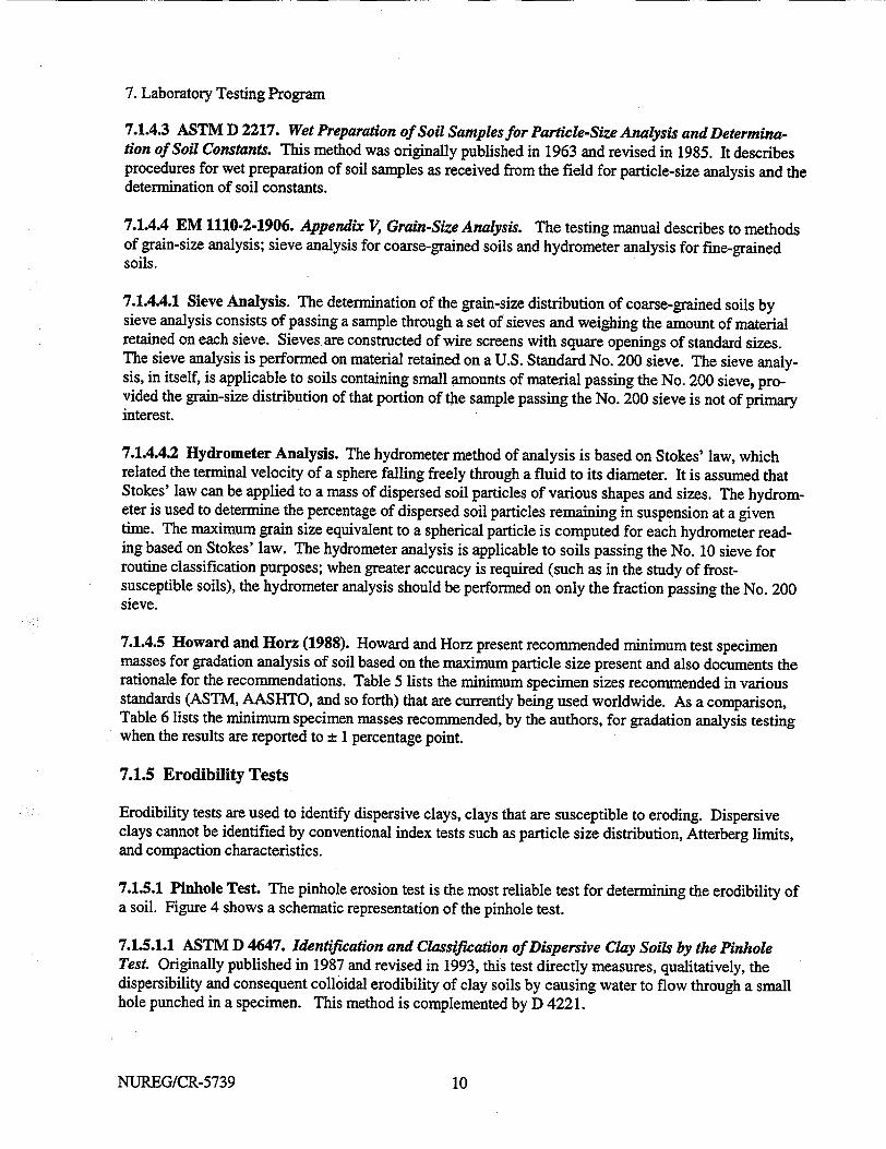
7.1.4.3 ASTM D 2217. Wet Preparation of Soil Samples for Particle-Size Analysis and Determination of Soil Constants. This method was originally published in 1963 and revised in 1985. It describes procedures for wet preparation of soil samples as received from the field for particle-size analysis and the determination of soil constants.
7.1.4.4 EM 1110-2-1906. Appendix V, Grain-Size Analysis. The testing manual describes to methods of grain-size analysis; sieve analysis for coarse-grained soils and hydrometer analysis for fine-grained soils.
7.1.4.4.1 Sieve Analysis. The determination of the grain-size distribution of coarse-grained soils by sieve analysis consists of passing a sample through a set of sieves and weighing the amount of material retained on each sieve. Sieves. are constructed of wire screens with square openings of standard sizes. The sieve analysis is performed on material retained on a U.S. Standard No. 200 sieve. The sieve analysis, in itself, is applicable to soils containing small amounts of material passing the No. 200 sieve, provided the grain-size distribution of that portion of the sample passing the No. 200 sieve is not of primary interest.
7.1.4.4.2 Hydrometer Analysis. The hydrometer method of analysis is based on Stokes' law, which related the terminal velocity of a sphere falling freely through a fluid to its diameter. It is assumed that Stokes' law can be applied to a mass of dispersed soil particles of various shapes and sizes. The hydrometer is used to determine the percentage of dispersed soil particles remaining in suspension at a given time. The maximum grain size equivalent to a spherical particle is computed for each hydrometer reading based on Stokes' law. The hydrometer analysis is applicable to soils passing the No. 10 sieve for routine classification purposes; when greater accuracy is required (such as in the study of frostsusceptible soils), the hydrometer analysis should be performed on only the fraction passing the No. 200 sieve.
7.1.4.5 Howard and Horz (1988). Howard and Horz present recommended minimum test specimen masses for gradation analysis of soil based on the maximum particle size present and also documents the rationale for the recommendations. Table 5 lists the minimum specimen sizes recommended in various standards (ASTM, AASHTO, and so forth) that are currently being used worldwide. As a comparison, Table 6 lists the minimum specimen masses recommended, by the authors, for gradation analysis testing when the results are reported to ± 1 percentage point.
7.1.5 Erodibility Tests
Erodibility tests are used to identify dispersive clays, clays that are susceptible to eroding. Dispersive clays cannot be identified by conventional index tests such as particle size distribution, Atterberg limits, and compaction characteristics.
7.1.5.1 Pinhole Test. The pinhole erosion test is the most reliable test for determining the erodibility of a soil. Figure 4 shows a schematic representation of the pinhole test.
7.1.5.1.1 ASTM D 4647. Identification and Classification of Dispersive Clay Soils by the Pinhole Test. Originally published in 1987 and revised in 1993, this test directly measures, qualitatively, the dispersibility and consequent colloidal erodibility of clay soils by causing water to flow through a small hole punched in a specimen. This method is complemented by D 4221.
NUREG/CR-5739 10

7. Laboratory Testing Program
7.1.5.1.2 EM 1110-2-1906. Appendix XIII, Pinhole Erosion Test for Identification of Dispersive
Clays. Detailed procedures for all four erosion tests (Pinhole test, Crumb tests, Soil Conservation Ser
vice (SCS), and Cylinder dispersion test) dispersion test are given in this testing manual. Some of the limitations of the pinhole test:
" undisturbed samples of high sensitivity may test as dispersive, while in nature they may be resistant to erosion,
" soils with high sodium (> 80 percent) and low total dissolved solids (< 0.4 meq/l) in the soil pore water may show nondispersive behavior in the test, while the soil may exhibit dispersive performance in the field.
7.1.5.2 Crumb Test. The crumb test is a simple means of identifying dispersive clays without requiring special equipment. It can be used in the laboratory or the field. The crumb test gives an indication only of dispersive behavior. If the crumb test indicates dispersion, then the soil is probably dispersive, however many dispersive soils (kaolinitic soils) do not react to the crumb test.
7.1.5.3 Soil Conservation Service (SCS) Dispersion Test. This test is sometimes referred to as the
double hydrometer test (Head, 1992). It estimates the propensity for dispersion in the field based on the degree of dispersion of clay particles achieved during the pre-treatment state of a hydrometer sedimentation test.
7.1.5.4 ASTM D 4221. Dispersive Characteristics of Clay Soil by Double Hydrometer. The original
guidance was published in 1983 and revised in 1990. It provides an indication of the natural dispersive characteristics of clay soils when used in conjunction with a test performed by method D 422 on a duplicate soil sample. This test is applicable only to soils with a plasticity index greater than 4 as determined by method D 4318 and more than 12 percent of the soil fraction finer than 5gm as determined by method D 422.
7.1.5.5 Cylinder Dispersion Test. This test was developed as an extension to the crumb test. Its main purpose was to examine soil behavior in the "fully softened" state when it was submerged in water, i.e.
under zero effective stress. This test is performed on a cylindrical specimen of remolded soil which has been consolidated from a slurry.
7.1.6 Compaction
7.1.6.1 ASTM D 698. Laboratory Compaction Characteristics of Soil Using Standard Effort
(12,400ft-lbf/ft' (600 kN-m/m3 )). This method was approved as a standard in 1991. It determines the relationship between water content and dry unit weight of soils compacted in a 4- or 6-in. (101.6- or 152.4-mm) diameter mold with a 5.5-lbf (24.4-N) rammer.
7.1.6.2 ASTM D 1557. Laboratory Compaction Characteristics of Soil Using Modified Effort
(56,000ft-lbf/fe (2,700 kN-m/m3)). Originally published in 1958 and revised in 1991, this method determines the relationship between water content and dry unit weight of soils compacted in a 4- or 6-in. (101.6 or 152.4-mm) diameter mold with a 10-lbf (44.5-N) rammer.
7.1.6.3 ASTM D 4253. Maximum Index Density and Unit Weight of Soils Using a Vibratory Table.
This standard procedure was published in 1983, edited in 1991, and republished in 1993. It covers four
procedures for determining the maximum index density/unit weight of cohesionless, free-draining soils using a vertically vibrating table.
NUREG/CR-573911
7. Laboratory Testing Program
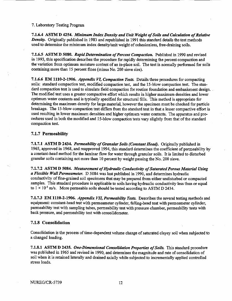
7.1.6.4 ASTM D 4254. Minimum Index Density and Unit Weight of Soils and Calculation of Relative Density. Originally published in 1983 and republished in 1991 this standard details the test methods used to determine the minimum index density/unit weight of cohesionless, free-draining soils.
7.1.6.5 ASTM D 5080. Rapid Determination of Percent Compaction. Published in 1990 and revised in 1993, this specification describes the procedure for rapidly determining the percent compaction and the variation from optimum moisture content of an in-place soil. The test is normally performed for soils containing more than 15 percent fines (minus No. 200 sieve size).
7.1.6.6 EM 1110-2-1906. Appendix VI, Compaction Tests. Details three procedures for compacting soils: standard compaction test, modified compaction test, and the 15-blow compaction test. The standard compaction test is used to simulate field compaction for routine foundation and embankment design. The modified test uses a greater compactive effort which results in higher maximum densities and lower optimum water contents and is typically specified for structural fills. This method is appropriate for determining the maximum density for large material, however the specimen must be checked for particle breakage. The 15-blow compaction test differs from the standard test in that a lesser compactive effort is used resulting in lower maximum densities and higher optimum water contents. The apparatus and procedures used in both the modified and 15-blow compaction tests vary slightly from that of the standard compaction test.
7.1.7 Permeability
7.1.7.1 ASTM D 2434. Permeability of Granular Soils (Constant Head). Originally published in 1965, approved in 1968, and reapproved 1994, this standard determines the coefficient of permeability by a constant-head method for the laminar flow for water through granular soils. It is limited to disturbed granular soils containing not more than 10 percent by weight passing the No. 200 sieve.
7.1.7.2 ASTM D 5084. Measurement of Hydraulic Conductivity of Saturated Porous Material Using a Flexible Wall Permeameter. D 5084 was last published in 1990, and determines hydraulic conductivity of fine-grained soil specimens that may be prepared from either undisturbed or compacted samples. This standard procedure is applicable to soils having hydraulic conductivity less than or equal to I x 10' mi/s. More permeable soils should be tested according to ASTM D 2434.
7.1.7.3 EM 1110-2-1906. Appendix VII, Permeability Tests. Describes the several testing methods and equipment: constant-head test with permeameter cylinder, falling-head test with permeameter cylinder, permeability test with sampling tubes, permeability test with pressure chamber, permeability tests with back pressure, and permeability test with consolidometer.
7.1.8 Consolidation
Consolidation is the process of time-dependent volume change of saturated clayey soil when subjected to a changed loading.
7.1.8.1 ASTM D 2435. One-Dimensional Consolidation Properties of Soils. This standard procedure was published in 1965 and revised in 1990, and determines the magnitude and rate of consolidation of soil when it is retained laterally and drained axially while subjected to incrementally applied controlled stress loads.
NUREG/CR-5739 12
7. Laboratory Testing Program
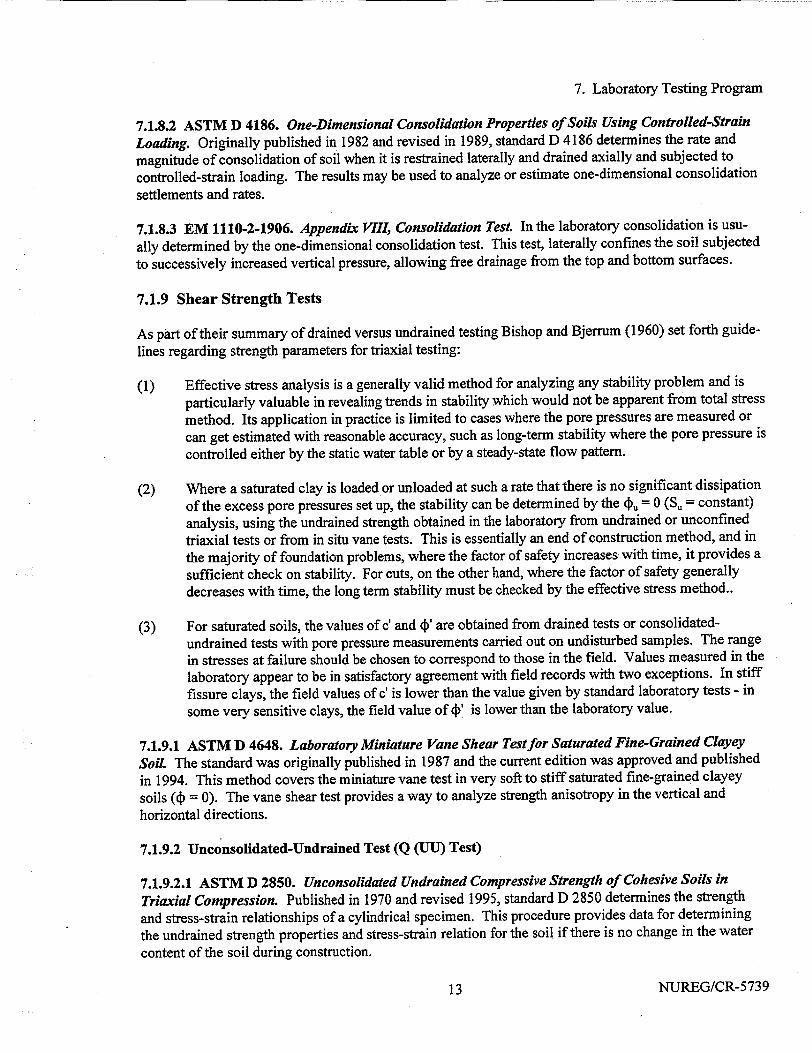
7.1.8.2 ASTM D 4186. One-Dimensional Consolidation Properties of Soils Using Controlled-Strain
Loading. Originally published in 1982 and revised in 1989, standard D 4186 determines the rate and
magnitude of consolidation of soil when it is restrained laterally and drained axially and subjected to
controlled-strain loading. The results may be used to analyze or estimate one-dimensional consolidation settlements and rates.
7.1.8.3 EM 1110-2-1906. Appendix VIII, Consolidation Test. In the laboratory consolidation is usu
ally determined by the one-dimensional consolidation test. This test, laterally confines the soil subjected
to successively increased vertical pressure, allowing free drainage from the top and bottom surfaces.
7.1.9 Shear Strength Tests
As part of their summary of drained versus undrained testing Bishop and Bjerrum (1960) set forth guide
lines regarding strength parameters for triaxial testing:
(1) Effective stress analysis is a generally valid method for analyzing any stability problem and is
particularly valuable in revealing trends in stability which would not be apparent from total stress
method. Its application in practice is limited to cases where the pore pressures are measured or
can get estimated with reasonable accuracy, such as long-term stability where the pore pressure is controlled either by the static water table or by a steady-state flow pattern.
(2) Where a saturated clay is loaded or unloaded at such a rate that there is no significant dissipation
of the excess pore pressures set up, the stability can be determined by the dpu = 0 (Su = constant)
analysis, using the undrained strength obtained in the laboratory from undrained or unconfined
triaxial tests or from in situ vane tests. This is essentially an end of construction method, and in
the majority of foundation problems, where the factor of safety increases with time, it provides a
sufficient check on stability. For cuts, on the other hand, where the factor of safety generally
decreases with time, the long term stability must be checked by the effective stress method..
(3) For saturated soils, the values of c' and (ý' are obtained from drained tests or consolidated
undrained tests with pore pressure measurements carried out on undisturbed samples. The range
in stresses at failure should be chosen to correspond to those in the field. Values measured in the
laboratory appear to be in satisfactory agreement with field records with two exceptions. In stiff
fissure clays, the field values of c' is lower than the value given by standard laboratory tests - in some very sensitive clays, the field value of 4)' is lower than the laboratory value.
7.1.9.1 ASTM D 4648. Laboratory Miniature Vane Shear Test for Saturated Fine-Grained Clayey
Soil The standard was originally published in 1987 and the current edition was approved and published
in 1994. This method covers the miniature vane test in very soft to stiff saturated fine-grained clayey
soils (d = 0). The vane shear test provides a way to analyze strength anisotropy in the vertical and
horizontal directions.
7.1.9.2 Unconsolidated-Undrained Test (Q (UU) Test)
7.1.9.2.1 ASTM D 2850. Unconsolidated Undrained Compressive Strength of Cohesive Soils in
Triaxial Compression. Published in 1970 and revised 1995, standard D 2850 determines the strength
and stress-strain relationships of a cylindrical specimen. This procedure provides data for determining
the undrained strength properties and stress-strain relation for the soil if there is no change in the water
content of the soil during construction.
NUREG/CR-573913
7. Laboratory Testing Program
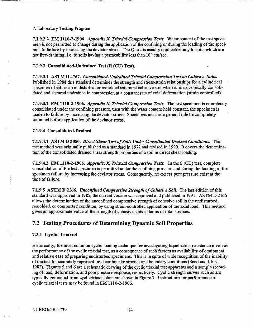
7.1.9.2.2 EM 1110-2-1906. Appendix X, Triaxial Compression Tests. Water content of the test specimen is not permitted to change during the application of the confining or during the loading of the specimen to failure by increasing the deviator stress. The Q test is usually applicable only to soils which are not free-draining, i.e. to soils having a permeability less than 10' cm/sec.
7.1.9.3 Consolidated-Undrained Test (R (CU) Test).
7.1.9.3.1 ASTM D 4767. Consolidated-Undrained Triaxial Compression Test on Cohesive Soils. Published in 1988 this standard determines the strength and stress-strain relationships for a cylindrical specimen of either an undisturbed or remolded saturated cohesive soil when it is isotropically consolidated and sheared undrained in compression at a constant rate of axial deformation (strain controlled).
7.1.9.3.2 EM 1110-2-1906. Appendix X, Triaxial Compression Tests. The test specimen is completely consolidated under the confining pressure, then with the water content held constant, the specimen is loaded to failure by increasing the deviator stress. Specimens must as a general rule be completely saturated before application of the deviator stress.
7.1.9.4 Consolidated-Drained
7.1.9.4.1 ASTM D 3080. Direct Shear Test of Soils Under Consolidated Drained Conditions. This test method was originally published as a standard in 1972 and revised in 1990. It covers the determination of the consolidated drained shear strength properties of a soil in direct shear loading.
7.1.9.4.2 EM 1110-2-1906. AppendixX, Triaxial Compression Tests. In the S (CD) test, complete consolidation of the test specimen is permitted under the confining pressure and during the loading of the specimen failure by increasing the deviator stress. Consequently, no excess pore pressure exist at the time of failure.
7.1.9.5 ASTM D 2166. Unconfined Compressive Strength of Cohesive Soil The last edition of this standard was approved in 1985, the current version was approved and published in 1991. ASTM D 2166 allows the determination of the unconfmed compressive strength of cohesive soil in the undisturbed, remolded, or compacted condition, by using strain-controlled application of the axial load. This method gives an approximate value of the strength of cohesive soils in terms of total stresses.
7.2 Testing Procedures of Determining Dynamic Soil Properties
7.2.1 Cyclic Triaxial
Historically, the most common cyclic loading technique for investigating liquefaction resistance involves the performance of the cyclic triaxial test, as a consequence of such factors as availability of equipment and relative ease of preparing undisturbed specimens. This is in spite of wide recognition of the inability of the test to accurately represent field earthquake stresses and boundary conditions (Seed and Idriss, 1982). Figures 5 and 6 are a schematic drawing of the cyclic triaxial test apparatus and a sample recording of load, deformation, and pore pressure response, respectively. Cyclic strength curves such as are typically generated from cyclic triaxial data are shown in Figure 7. Instructions for performance of cyclic triaxial tests may be found in EM 1110-2-1906.
NUREG/CR-5739 14

7. Laboratory Testing Program
Previous studies have demonstrated that cyclic triaxial strengths (in fact, strengths determined from any unidirectional loading test) are higher than those expected to produce equivalent effects in the field (Seed, 1976). Reduction factors were developed to adjust laboratory cyclic test strengths to estimate field liquefaction resistance (e.g., multiplication of cyclic triaxial strengths by factors ranging from 0.57 to 1 for soils where the lateral earth pressure coefficient, Ko, ranges from 0.4 to 1, respectively, described by Seed and Idriss, 1982). Estimation of field cyclic strengths from laboratory cyclic test results may not be possible by universal application of simple factors; recent research has shown that the comparison between cyclic triaxial and cyclic simple shear strengths depend on gradation, density, and soil type (Koester, 1992b). A companion report on liquefaction potential evaluation for nuclear power facilities details the state-of-the-art applied to cyclic strength evaluation (Koester and Sharp, 1999).
The constant volume condition implicitly assumed to accompany undrained testing behavior required for cyclic triaxial tests may be compromised in coarse-grained soil specimens by membrane compliance. The compliance imparts compressibility that is a relic of the test boundary conditions and therefore not representative of true, in situ behavior. The elastic membrane used to encapsulate soil specimens in, for example, triaxial tests, may intrude into the voids at the circumferential surface of the cylindrical specimen. Research by Evans (1987), Hynes (1988), and others have shown that, in cyclic tests, pore water pressures developed within the soil specimen may be partially relieved by these surficial voids, since the confining fluid will not resist the tendency for the membrane to deform. Membrane compliance may result in artificially high undrained cyclic strengths (resistance to liquefaction) of individual specimens, leading to unconservative evaluation of the liquefaction resistance of a deposit in situ. Membrane compliance is a function of gradation, and the correction that must be applied to adjust cyclic strengths is a function of specimen size, confining pressure, and other factors. The magnitude of the membrane compliance effect on cyclic strength is exemplified by the data represented in Figure 8, from Hynes (1988), which may serve as a correction chart.
7.2.1.1 Tatsuoka, et al. (1994). This report covers the measuring of local strains in cyclic triaxial tests was reported in Tatsuoka, et al. (1994). The deformation properties of sand and gravel were evaluated by cyclic loading triaxial tests and monotonic loading triaxial compression tests using small and large triaxial apparatuses. The results were compared with those from other testing methods. Two types of local gages set on the lateral surface of the specimen measured local axial and radial strains. The authors concluded that:
(1) Local measurements of axial strain are imperative for accurate evaluation of stiffness of granular materials (sands and gravels) in both monotonic and cyclic loading triaxial tests. This is also the case for measuring damping characteristics in cyclic loading triaxial tests.
(2) In triaxial tests at a constant confining pressure, accurate radial strains can be obtained by measuring the change in the specimen diameter.
(3) Stiffness and damping during cyclic loading of granular materials for a strain range from about 0.0001 percent to about 1.0 percent can be obtained from static cyclic loading tests (i.e., very low frequency tests). The initial elastic stiffness can be estimated also by relevant monotonic loading triaxial compression tests, since the behavior is nearly elastic at strains less than about 0.001 percent.
(4) It is suggested that field values of stiffness at small strains (say, up to 0.1 percent) under monotonic and cyclic loading conditions can be estimated from field shear wave velocities while taking into account that its dependency on pressure level and strain level. The strain level-
NUREG/CR-573915
7. Laboratory Testing Program
dependency is obviously different between monotonic and cyclic loading tests and between torsional and triaxial tests.
7.2.1.2 Vucetic and Dobry (1991). Vucetic and Dobry studied the influence of plastic index on the cyclic stress-strain parameters of saturated soils. Figure 9 shows the effect of PI on the location of the modulus reduction curve G/Gm. (G - shear modulus; Gm. - shear modulus at small strains) versus cyclic shear strain y,, and on the material damping ratio X versus y, curve. These charts are based on experimental data from 16 publications on testing of normally consolidated and overconsolidated clays (OCR =
1 - 15), and sands. From the charts, in the paper it is shown that the PI may strongly control G/G, and I for a wide variety of soils. If for a given y, the PI increases, G/Gmx, rises and X is reduced. Also presented was the influence of the PI on the rate of modulus degradation with the number of cycles in normally consolidated clays. Vucetic and Dobry (1991) concluded that soils with higher plasticity tend to have a more linear cyclic stress-strain response at small strains and to degrade less at larger y, than soils having lower PI. Possible reasons for this behavior are discussed in their paper. The charts in Figure 9 are recommended for use in preliminary seismic site-response evaluations and microzonation. Because of the scatter of the data points used to produce the charts, they should be applied with caution.
7.2.2 Resonant Column
7.2.2.1 ASTM D 4015. Modulus and Damping of Soils by the Resonant-Column Method Published in 1981 and revised 1992, this standard determines the shear modulus, shear damping, rod modulus (Young's modulus), and rod damping for solid cylindrical specimens of soil in undisturbed and remolded conditions by vibration using the resonant column.
7.2.2.2 Andreasson (1981). Andriasson (1981) studied the shear modulus of a soft, high-plastic clay under dynamic loading conditions. Two resonant column devices, designed and built at Chalmers University of Technology in Sweden, testing both solid and hollow soil samples, were used in the test. One of the two resonant column devices is shown in Figure 10. Andr~asson concluded that the initial shear modulus determined by shear wave velocity measurements in-situ and resonant column tests in the laboratory were in good correlation, provided that the laboratory test results were extrapolated to a time period corresponding to the age of the soil deposit.
The reduction of shear modulus with increasing shear strain amplitude was studied in the dynamic loading screw-plate tests in-situ and in the high amplitude resonant column tests in the laboratory. Good correlation between the field and laboratory test results was achieved, if the shear strain within the influenced soil in the screw-plate tests was calculated as 0.75 times the relative deformation of the screw plate.
7.2.3 Resonant Column and Torsional Shear
7.2.3.1 Zavoral, et al. (1994). Zavoral, et al. (1994) evaluated the effect of frequency on the dynamic response of clay. Details of the modified apparatus are described and test results over a wide range of frequencies at different strain levels were presented. The results show that the dynamic shear modulus of samples tested by the resonant column in axial vibration was always greater than the dynamic shear modulus of the same samples tested at lower frequencies in torsional shear. Samples were tested in torsional shear at various frequencies to confirm that the increase in shear modulus was due to frequency (strain rate). Results indicated that the shear modulus always increased with frequency, though the effect was fairly minor. No observable effect of frequency on damping ratio was measured for samples tested in
NUREG/CR-5739 16
7. Laboratory Testing Program
either resonant column or torsional shear modes. There also was no significant variation in damping ratio for samples tested in torsional shear under various frequencies.
7.2.3.2 Kim, et al. (1991). Kim, et al. investigates the assumption that material damping in shear of soil
measured by hysteresis loops is zero at small strains, strains less than about 0.001 percent. A single piece
of equipment is used for both the torsional shear (TS) and resonant column (RC) tests (Figure 11). Mate
rial damping in shear for a dry sand and a compacted clay were obtained by varying the strain level, frequency of the excitation and number of loading cycles. Their results show that for the dry sand the damping ratios obtained from the RC and TS shear test match at shearing strains below about 0.002 per
cent (Figure 12). At higher strains, the damping ratios are sensitive to number of loading cycles (Figure 13). Damping values obtained from the first TS cycle are much larger than those computed from later cycles or from the RC test. Damping ratios from TS and RC test are essentially equal at the same strain level and the same number of cycles. The effect of frequency on material damping is negligible for this dry sand.
For the compacted clay, the damping ratios obtained from the TS and RC tests are different over the complete strain range (from 0.0004 to 0.05 percent). This difference results from the difference in frequencies used in the two methods of testing. However, the effect of frequency in the TS test does not begin to increase material damping until the frequency exceeds about 5 Hz. The effect of the number of loading cycles is negligible in the compacted clay. The device was modified so that damping measurements could be made over strains ranging from about 10' to 10' percent.
7.3 Testing Procedures of Determining Engineering Properties of Rock
7.3.1 Porosity
ASTM D 4404. Determination of Pore Volume and Pore Volume Distribution of Soil and Rock by Mercury Intrusion Porosimetry. The current edition of ASTM D 4404 was last reapproved in 1992. This test method describes the determination of pore characteristics of soil and rock for the range of apparent pore entrance diameters of about 100 gim and 2.5 nm (0.0025 gtm). The process uses mercury intrusion under varying pressures and will only measure volume of pores that are open to the outside of a soil or rock fragment. The size and volume of pores affects the integrity and behavior of soil or rock. The standard describes special porosimeter equipment and testing limitations.
7.3.2 Permeability
ASTM D 4525. Permeability of Rocks by Flowing Air. The current edition of this testing method was published in 1990. It determines the coefficient of specific permeability for the flow of air through rocks. Designed to measure the permeability to air of a small sample of rock, by extrapolation, this method can also be used to determine an equivalent of the liquid permeability.
7.3.3 Seismic Velocity
ASTM D 2845. Laboratory Determination of Pulse Velocities and Ultrasonic Elastic Constants of Rock. The original version of this standard was published in 1969; the last previous edition was in 1983
and reapproved in 1990. This method describes equipment and procedures for measurement of the pulse velocities of compression waves and shear waves in rock in the laboratory. It also determines the ultra
sonic elastic constants of an isotropic rock.
NUREG/CR-573917
7. Laboratory Testing Program
7.3.4 Direct Tensile Strength
ASTM 2936. Direct Tensile Strength of Intact Rock Core Specimens. Originally published in 1971 and reapproved in 1995, this standard determines the tensile strength of intact cylindrical rock. To determine the failure condition of a structure the tensile strength is used as the failure strength for the structure.
7.3.5 Unconfined Compression
7.3.5.1 ASTM D 2938. Unconfined Compressive Strength of Intact Rock Core Specimens. This standard method was originally published in 1971, reapproved and published again in 1995. The apparatus, instrumentation, and procedures for the determination of the unconfined compressive strength of intact rock core specimens are discussed in the method. The unconfined compressive strength is used in design formulas and sometimes as an index property for selecting the appropriate excavation technique.
7.3.5.2 ASTM D 3148. Elastic Moduli of Intact Rock Core Specimens in Uniaxial Compression. The currents edition of this method was published in 1993, it describes the procedures used to determine the elastic moduli of intact rock core specimens in uniaxial compression. The stress-axial strain and the stress-lateral strain curves, along with the Young's modulus and Poisson's ratio can be determined by this standard.
7.3.5.3 ASTM D 3967. Splitting Tensile Strength of Intact Rock Core Specimens. The current edition of the standard test method was published in 1995. It determines the splitting tensile strength of rock by diametral line compression of a disk. This test is an alternative to the direct uniaxial tensile test which is difficult and expensive for routine testing.
7.3.6 Triaxial Compression
7.3.6.1 ASTM D 5407. Elastic Moduli of Undrained Intact Rock Core Specimens in Triaxial Compression Without Pore Pressure Measurements. Approved and published in 1993, ASTM D 5407 determines the elastic moduli of intact rock core specimens in undrained triaxial compression. The stress-axial strain and the stress-lateral strain curves along with Young's modulus and Poisson's ration can be determined using the procedures detained in the standard method.
7.3.6.2 ASTM D 2664. Triaxial Compressive Strength of Undrained Rock Core Specimens Without Pore Pressure Measurements. This method was originally published in 1967. The current edition was approved and published in 1986. It covers the determination of the strength of cylindrical rock core ,specimens in an undrained state under triaxial compression loading. The data provided by this method is useful in determining the strength and elastic properties of rock without pore pressure measurements.
7.3.7 Slake Durability
Slaking tests are valuable when the project is to be found on or within moisture-sensitive clays and clay shales, and foundation design requirements indicate that the foundation and cut slope areas will be exposed temporarily to wetting and drying conditions.
NUREG/CR-5739 18
8. Conclusion
ASTM D 4644. Slake Durability of Shales and Similar Weak Rocks. This test method was published in 1987, and describes the procedures used to determine the slake durability index of shale and rock after two drying and wetting cycles with abrasion.
8 CONCLUSION
The main purpose of this document was to provide basic information on laboratory testing methods that have been developed and put into practice since the publication of the current Regulatory Guide 1.138 (1972). It was not the intent of the authors to describe in detail the testing methods discussed (i.e., detailed equipment requirements, detailed procedures, etc.), only to give a brief description of current research and accepted methods available. The inclusion of any particular testing method or equipment should not be perceived as an endorsement by the authors. This decision is left solely up to the Nuclear Regulatory Commission.
Although it would be impossible to describe all of the research conducted in laboratory testing since 1972, this document has covered some of the most accepted methods and recommends that as extended research, the users should consider the references listed by a particular method.
REFERENCES
1. Allison, L. E. 1960. "Wet combustion apparatus and procedure for organic and inorganic carbon in soil." Proceedings, Soil Science Society of America. Vol. 24, pp. 36-40.
2. American Society of Agronomy and American Society for Testing and Materials. 1965. "Methods of soil analysis, Parts 1 and 2." Americas Society of Agronomy, Inc., Madison, Wisconsin.
3. American Society for Testing and Materials. 1996. "Annual Book of Standards: Soil and Rock." Vols. 04.08 and 04.09.
4. Andrdasson, B. A. 1981. "Dynamic deformation characteristics of soft clay." Proceedings, International Conference on Recent Advances in Geotechnical Earthquake Engineering and Soil Dynamics. Vol. 1, pp. 65-70.
5. Bishop, A. W. and Bjerrumn, L. 1960. "The relevance of the triaxial test to the solution of stability problems," Proceedings, ASCE Research Conference on Shear Strength of Cohesive Soils, pp. 437-501.
6. Bishop, A. W. and Henkel, D. J. 1962. "The measurement of soil properties in the triaxial test," 2nd ed., Edward Arnolds, Ltd., London.
7. Bobrowski, L. J., Jr. and Griekspoor, D. M. 1992. "Determination of the plastic limit of a soil by means of a rolling device." Geotechnical Testing Journal, GTJODJ, Vol. 15, No. 3, pp. 284-287.
NUREG/CR-573919
References
8. Brown, P. T. and Chow, J. C.-P. 1988. "Prevention of sample deterioration." Geotechnical Testing Journal, GTJODJ, Vol. 11, No. 4, pp. 296-300.
9. Buell, A. W. 1950. "Porosity and permeability analysis." Subsurface Geologic Methods (A Symposium), 1st ed., Colorado School of Mines, Golden, Colorado. pp. 168-175.
10. Clayton, C. R. I., Matthews, M. C., and Simons, N. E. 1995. "Site investigation." Blackwell Science, Ltd.
11. Das, B. M. 1992. "Soil mechanics laboratory manual." 4' ed., Engineering Press, Inc., San Jose, California.
12. Department of the Army. 1986. EM 1110-2-1906, "Laboratory soils testing," U.S. Army Corps of Engineers, Washington, D.C.
13. Department of the Army. 1986. EM 1110-2-1909, "Calibration of laboratory soils testing equipment," U.S. Army Corps of Engineers, Washington, D.C.
14. Evans, M. 1987. "Undrained Cyclic Triaxial Testing of Gravels - The Effects of Membrane Compliance." Ph.D. Dissertation, University of California, Berkeley, CA.
15. Evans, M. D., and Zhou, S. 1995. "Liquefaction behavior of sand-gravel composites," Journal of Geotechnical Engineering, Vol. 121, No. 3, pp. 287-298.
16. Finn, W. D. L. et al. 1971. "Sand liquefaction in triaxial and simple shear tests," Journal of the Soil Mechanics and Foundations Division, ASCE, Vol. 97, No. SMS, pp. 639-659.
17. Francher, G. H. 1950. "The porosity and permeability of elastic sediments and rocks." Subsurface Geologic Methods (A Symposium), 2nd ed., Colorado School of Mines, Golden, Colorado, pp. 685712.
18. Franklin, J. A. and Chandra, R. 1972. "The slake-durability test." International Journal of Rock Mechanics and Mineral Science, Vol. 9, Pergamon Press, Ltd., London, pp. 325-341.
19. Germaine, J. T. and Ladd, C. C. 1988. "Triaxial testing of saturated cohesive soils." Advanced Triaxial Testing of Soil and Rock, ASTM STP 977, Robert T. Donaghe, Ronald C. Chaney, and Marshall L. Silver, Eds., American Society for Testing and Materials, Philadelphia, pp. 421-459.
20. Gilbert, P. A. 1988. "Computer controlled microwave oven system for rapid water content determination." Technical Report GL-88-21, U.S. Army Engineer Waterways Experiment Station, Vicksburg, MS.
21, Gilbert, P. A. 1990. "Computer-controlled microwave drying of potentially difficult organic and inorganic soils." Technical Report GL-90-26, U.S. Army Engineer Waterways Experiment Station, Vicksburg, MS.
22. Gillott, J. E. 1968. "Clay in Engineering Geology." Elsevier, New York, NY, pp. 186 - 196.
NUREG/CR-5739 20

References
23. Graham, J., Jamieson, M. R., Ho, D. Y.-F., and Azizi, F. 1990. "Influence of storage and reconsolidation procedures on clay properties." Geotechnical Testing Journal, GTJODJ, Vol. 13, No. 4, pp. 280-290.
24. Gregory, A. R. 1963. "Shear wave velocity measurements of sedimentary rock samples under compression." Proceedings, 5th Symposium on Rock Mechanics. University of Minnesota, The McMillan Company, New York, pp. 439-471.
25. Hardin, B. 0. 1970. "Suggested methods of test for shear modulus and damping of soils by the resonant column," Special Procedures for Testing Soil and Rock for Engineering Purposes. ASTM STP 479, American Society for Testing and Materials, Philadelphia, Pennsylvania.
26. Head, K. H. 1992. "Manual of soil laboratory testing volume 1: Soil classification and compaction tests." Second Ed., Halsted Press: an imprint of John Wiley & Sons Inc., New York -Toronto.
27. Head, K. H. 1994. "Manual of soil laboratory testing volume 2: Permeability, shear strength and compressibility tests." Second Ed., Pentech Press, London.
28. Heck, W. J. 1972. "Development of equipment for studying pore pressure effects in rock." Proceedings, Tenth Symposium on Rock Mechanics, University of Texas at Austin, American Institute of Mining, Metallurgical, and Petroleum Engineers, Inc., New York, pp. 243-266.
29. Holtz, W. G. 1970a. "Suggested methods of test for one-dimension expansion and uplift pressure of clay soils." Special Procedures for Testing Soil and Rock for Engineering Purposes, ASTM STP 479, American Society for Testing and Materials, Philadelphia, Pennsylvania, pp. 198-205.
30. Holtz, W. G. 1970b. "Suggested methods of test for permeability of undrained soil or rock specimens." Special Procedures for Testing Soil and Rock for Engineering Purposes, ASTM STP 479, American Society for Testing and Materials, Philadelphia, Pennsylvania, pp. 150-156.
31. Howard, A. K. and Horz, R. C. 1988. "Minimum test specimen for gradation analysis." Geotechnical Testing Journal, GTJODJ, Vol. 11, No. 3, pp. 213-217.
32. Hynes, M. E. 1988. "Pore Pressure Generation Characteristics of Gravel Under Undrained Cyclic Loading," Ph.D. Dissertation, University of California, Berkeley, CA.
33. Kim, D. S., Stokoe, K. H., and Roesset, J. M. 1991. "Characterization of material damping of soils using resonant column and torsional shear tests." Soil Dynamics and Earthquake Engineering, Computation Mechanics Publications, United Kingdom.
34. Koester, J. P. 1992a. "The influence of test procedures on correlation of Atterberg limits with liquefaction in fine-grained soils." Geotechnical Testing Journal, GTJODJ, Vol. 15, No. 4, pp. 352-361.
35. Koester, J. P. 1992b. "Cyclic strength and pore pressure generation characteristics of fine grained soils," Ph.D. thesis, University of Colorado, Boulder, December.
NUREG/CR-573921
References
36. Koester, J. P. and Sharp, M. K. 1999. "Evaluation of soil liquefaction potential for foundation of nuclear facilities - technical bases for regulatory guide," submitted for publication by the U.S. Nuclear Regulatory Commission in NUREG contractor report, January 1999.
37. Krinitzsky, E. L. 1970. "Radiography in the earth sciences and soils mechanics." Plenum Press, New York.
38. Lambe, T. W. 1951. "Soil testing for engineers." John Wiley & Sons, Inc., New York.
39. Liu, C. and Evett, J. B. 1990. "Soil properties testing, measuring, and evaluation." 2' ed. Prentice Hall, Englewood cliffs, New Jersey.
40. Obert, Leonard, and Duvall. 1967. "Rock mechanics and the design of structures in rock." John Wiley & Sons, Inc., New York.
41. Perry, E. G. 1975. "Piping in earth dams constructed of dispersive clay, literature review and design of laboratory tests." Technical Report S-75-15, U.S. Army Waterways Experiment Station, Vicksburg, Mississippi.
42. Richart, F. E. et al. 1970. "Vibrations of soils and foundations." Prentice-Hall, Inc., Englewood Cliffs, New Jersey.
43. Sallfors, G. 1989. "Quality assurance in laboratory testing." Proceedings, Twelfth International Conference on Soil Mechanics and Foundation Engineering. Vol. 1, No. 12, pp. 105-106.
44. Schmidt, N. 0. 1970. "Suggested method of testing for organic carbon content of soil by wet combustion." Special Procedures for Testing Soil and Rock for Engineering Purposes, American Society for Testing and Materials, STP 479, Philadelphia, Pennsylvania.
45. Scholey, G. K., Frost, J. D., and Jamiolkowski, M. 1995. "A review of instrumentation for measuring small strains during triaxial testing of soil specimens." Geotechnical Testing Journal, GTJODJ. Vol. 18, No. 2, pp 137.
46. Seed, H. B. 1976. "Evaluation of soil liquefaction effects on level ground during earthquakes," Liquefaction Problems in Geotechnical Engineering, Preprint No. 2752, ASCE National Convention, Philadelphia, pp 1-104.
47. Seed, H. B. and Idriss, I. M. 1982. "Ground motions and soil liquefaction during earthquakes." Monograph Series, Earthquake Engineering Research Institute, University of California, Berkeley, CA.
48. Shannon & Wilson, Inc. and Agbabian-Jacobsen Associates. 1972. "Soil behavior under earthquake loading conditions; State-of-the-art evaluation of soil characteristics for seismic response analysis." Report for U.S. Atomic Energy Commission.
49. Sherard, J. L., Dunningan, L. P., Decker, R. S., and Steele, E. G. 1976. "Pinhole test for identifying dispersive spills." Journal of the Geotechnical Engineering Division, American Society of Civil Engineers, Vol. 102, No. GT 1, pp. 69-85.
NUREG/CR-5739 22
References
50. Sherard, J. L., Dunningan, L. P., and Decker, R. S. 1976. "Identification and nature of dispersive soils," Journal of the Geotechnical Engineering Division, ASCE, Vol. 102, No. GT 4, pp. 287-301.
51. Silver, M. L. and Park, T. K. 1975. "Testing procedure effects on dynamic soil behavior." Journal of the Geotechnical Engineering Division, ASCE, Vol. 101, No. GT 10, pp. 1061-1083.
52. Silver, M. L. 1976. "Laboratory triaxial testing procedures to determine the cyclic strength of soils." NUREG-003 1, U.S. Nuclear regulatory Commission.
53. Silver, M. L. 1976. "Cyclic triaxial strength of standard test sand," Journal of the Geotechnical Engineering Division, ASCE, Vol. 102, No. GT 5, pp. 511-523.
54. Silver, M. L. and Seed, H. B. 1971. "Deformation characteristics of sand under cyclic." Journal of the Soil Mechanics and Foundations Division, ASCE, Vol. 97, No. SM 8, pp. 1081-1098.
55. Soil Conservation Service. 1967: "Soil Survey Laboratory Methods and Procedures for Collecting Soil Samples." Soil Survey Investigations report No. 1, U.S. Soil Conservation Service, Washington, D.C.
56. Talesnick, M. and Frydman, S. 1990. "The preparation of hollow cylinder specimens from undisturbed tube samples of soft clay." Geotechnical Testing Journal, GTJODJ, Vol. 13, No. 3, pp. 243-249.
57. Tatsuoka, F., Teachavorasinskun, S., Dong, J., Kohata, Y., and Sato, T. 1994. "Importance of measuring local strains in cyclic triaxial tests on granular materials," Dynamic Geotechnical Testing II, ASTM STP 1213, American Society for Testing and Materials, Philadelphia, PA.
58. Torres, N. 1998. "Field investigations for foundations of nuclear power facilities," submitted for publication by the U.S. Nuclear Regulatory Commission in NUREG contractor report, December.
59. Thiers, G. R. and Seed, H. B. 1968. "Cyclic stress-strain characteristics of clay." Journal of the Soil Mechanics and Foundations Division, ASCE, Vol. 94, No. SM 2, pp. 555-569.
60. Torrey, V. H. a, and Donaghe. R. T. 1991. "Compaction control of earth-rock mixtures," Technical Report GL-91-16, U.S. Army Engineer Waterways Experiment Station, Vicksburg, Mississippi.
61. U.S. Army Corps of Engineers Rock Testing Handbook. 1993. "Test Standards 1993, Part I," U.S. Army Engineers, Prepared by Geotechnical Laboratory, Waterways Experiment Station, Vicksburg, MS.
62. Vucetic, M. and Dobry, R. 1991. "Effect of soil plasticity on cyclic response." ASCE Journal of Geotechnical Engineering. Vol. 117, No. 1, pp 89-17.
63. Warshaw, C. M. and Roy, R. 1961. "Classification and a scheme for the identification of layer silicates." Bulletin of the Geological Society of America, Vol. 72, pp. 1455-1492.
64. Zavoral, D. Z. and Campanella, R. G. 1994. "Frequency effects on damping/modulus of cohesive soil." Dynamic Geotechnical Testing II, ASTM STP 1213, Ronald J. Ebelhar, Vincent P. Dmevich, and Bruce L. Kutter, Eds., American Society for Testing and Materials, Philadelphia, PA.
NUREG/CR-573923
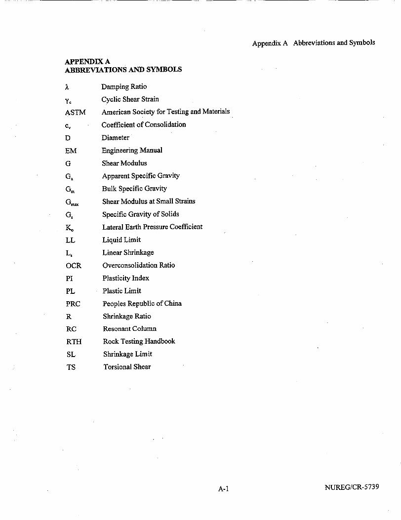
Appendix A Abbreviations and Symbols
APPENDIX A ABBREVIATIONS AND SYMBOLS
,X Damping Ratio
YC Cyclic Shear Strain
ASTM American Society for Testing and Materials
c, Coefficient of Consolidation
D Diameter
EM Engineering Manual
G Shear Modulus
Ga Apparent Specific Gravity
Gm Bulk Specific Gravity
Gm. Shear Modulus at Small Strains
G. Specific Gravity of Solids
K. Lateral Earth Pressure Coefficient
LL Liquid Limit
Lý Linear Shrinkage
OCR Overconsolidation Ratio
PI Plasticity Index
PL Plastic Limit
PRC Peoples Republic of China
R Shrinkage Ratio
RC Resonant Column
RTH Rock Testing Handbook
SL. Shrinkage Limit
TS Torsional Shear
NUREG/CR-5739A-1
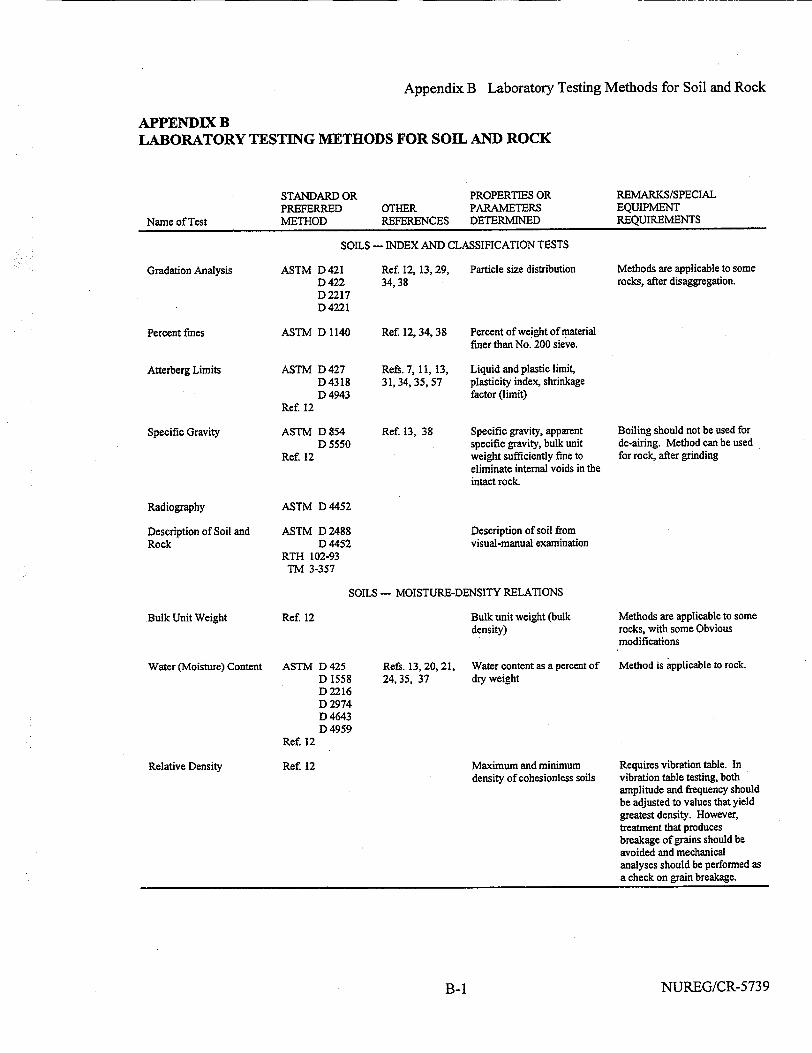
Appendix B Laboratory Testing Methods for Soil and Rock
APPENDIX B LABORATORY TESTING METHODS FOR SOIL AND ROCK
STANDARD OR PREFERRED METHOD
OTHER REFERENCES
PROPERTIES OR PARAMETERS DETERMINED
REMARKS/SPECIAL EQUIPMENT REQUIREMENTS
SOILS -- INDEX AND CLASSIFICATION TESTS
Gradation Analysis
Percent fines
Atterberg Limits
Specific Gravity
Radiography
Description of Soil and Rock
ASTM D421 D 422 D 2217 D 4221
ASTM D 1140
ASTM D 427 D 4318 D 4943
Ref. 12
ASTM D 854 D 5550
Ref. 12
ASTM D 4452
ASTM D 2488 D 4452
RTH 102-93 TM 3-357
Ref. 12, 13,29, 34,38
Ref. 12, 34, 38
Refs. 7, 11, 13, 31,34,35,57
Particle size distribution Methods are applicable to some rocks, after disaggregation.
Percent of weight of material finer than No. 200 sieve.
Liquid and plastic limit, plasticity index, shrinkage factor (limit)
Ref. 13, 38 Specific gravity, apparent specific gravity, bulk unit weight sufficiently fine to eliminate internal voids in the intact rock.
Boiling should not be used for de-airing. Method can be used for rock, after grinding
Description of soil from visual-manual examination
SOILS - MOISTURE-DENSITY RELATIONS
Bulk Unit Weight
Water (Moisture) Content
Relative Density
Ref. 12 Bulk unit weight (bulk density)
ASTM D 425 D 1558 D 2216 D 2974 D 4643 D 4959
Ref 12
Ref. 12
Refs. 13, 20,21, 24,35, 37
Water content as a percent of dry weight
Maximum and minimum density of cohesionless soils
Methods are applicable to some rocks, with some Obvious modifications
Method is applicable to rock.
Requires vibration table. In vibration table testing, both amplitude and frequency should be adjusted to values that yield greatest density. However, treatment that produces breakage of grains should be avoided and mechanical analyses should be performed as a check on grain breakage.
NUREG/CR-5739
Name of Test
B-1
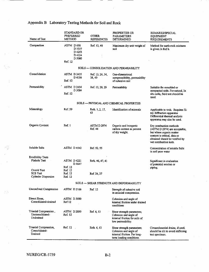
Appendix B Laboratory Testing Methods for Soil and Rock
STANDARD OR PREFERRED METHOD
OTHER REFERENCES
PROPERTIES OR PARAMETERS DETERMINED
REMARKS/SPECIAL EQUIPMENT REQUIREMENTS
Ref 13,40 Maximum dry unit weight of soil
Method for earth-rock mixtures is given in Ref 6.
SOILS - CONSOLIDATION AND PERMEABILITY
Consolidation
Permeability
ASTM D 2435 D4186
Ref. 12
ASTM D 2434 D 5084
Ref. 12
Ref 13,26, 34, 38,40
One-dimensional compressibility, permeability of cohesive soil
Ref. 13,28,29 Permeability
SOILS - PHYSICAL AND CHEMICAL PROPERTIES
Ref 59
Organic Content
Soluble Salts
Erodibility Tests Pinhole Test
Crumb Test SCS Test Cylinder Dispersion
Unconfined Compression
Direct Shear, Consolidated-drained
Triaxial Compression, UnconsolidatedUndrained
Triaxial Compression, ConsolidatedDrained
Refs. 1, 2,17, 63
Ref. I
Identification of minerals
ASTM D 2974 Organic and inorganic Ref. 44 carbon content as percent
of dry weight.
ASTM D 4542
ASTM D 4221 D 4647
Ref. 12 Ref 12 Ref. 12 Ref. 12
Ref 52, 55
Refs. 46, 47, 41
Suitable for remolded or compacted soils. For natural, In situ soils, field test should be used.
Applicable to rock. Requires Xray diffraction apparatus Differential thermal analysis apparatus may also be used.
Dry combustion methods (ASTM D 2974) are acceptable, but where organic matter content is critical, data so obtained should be verified by wet combustion tests.
Concentration of soluble Salts in soil pore water
Significant in evaluation of potential erosion or piping.
Ref. 24, 27
SOILS - SHEAR STRENGTH AND DEFORMABILITY
ASTM D 2166
ASTM D 3080 Ref 12
ASTM D 2850 Ref. 12
Ref. 12
Ref. 12
Ref. 6, 13
Refs. 6, 13
Strength of cohesive soil in uniaxial compression.
Cohesion and angle of internal friction under drained conditions
Shear strength parameters; Cohesion and angle of internal friction for soils of low permeability.
Shear strength parameters; Cohesion and angle of internal friction. For longterm loading conditions.
Circumferential drains, if used, should be slit to avoid stiffening test specimen.
NUREG/CR-5739
Name of Test
Compaction ASTM D 698 D 1557 D 4253 D 4254 D 5080
Ref. 12
Mineralogy
B-2
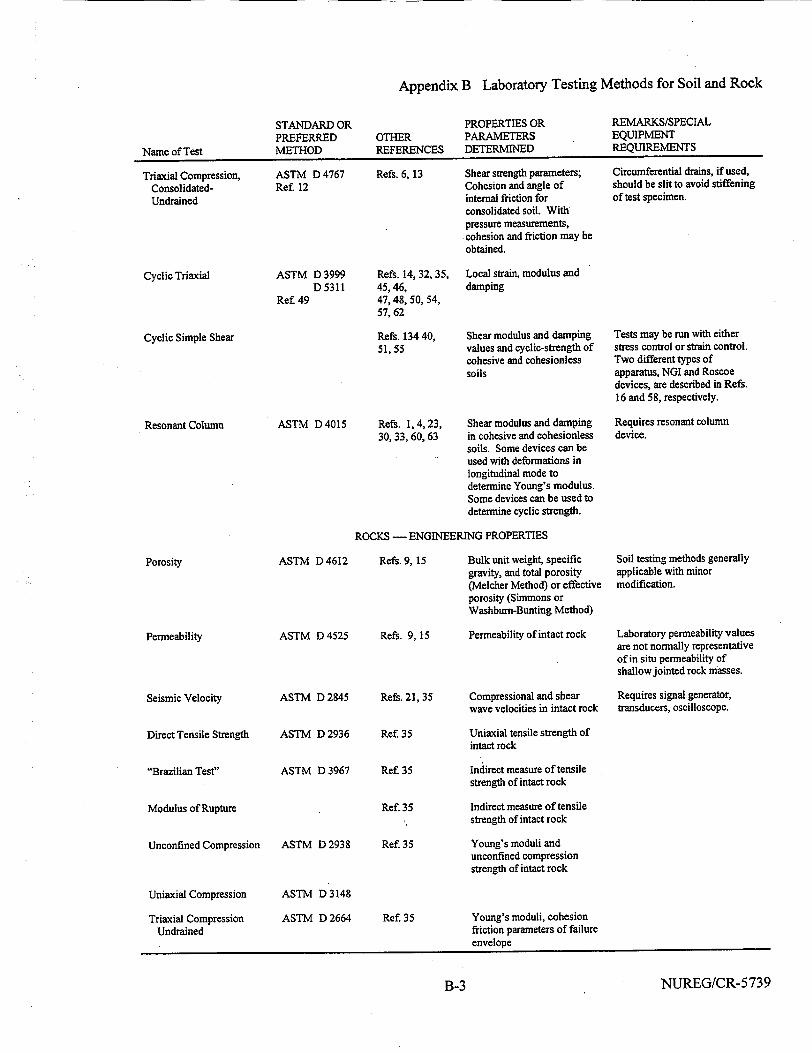
Appendix B Laboratory Testing Methods for Soil and Rock
STANDARD OR PREFERRED METHOD
OTHER REFERENCES
PROPERTIES OR PARAMETERS DETERMINED
REMARKS/SPECIAL EQUIPMENT REQUIREMENTS
Triaxial Compression, ConsolidatedUndrained
Cyclic Triaxial
ASTM D 4767 Ref 12
ASTM D 3999 D 5311
Ref 49
Cyclic Simple Shear
Resonant Column ASTM D 4015
Refs. 6, 13
Refs. 14, 32,35, 45,46, 47,48, 50, 54, 57,62
Shear strength parameters; Cohesion and angle of internal friction for consolidated soil. With pressure measurements, cohesion and friction may be obtained.
Local strain, modulus and damping
Refs. 134 40, Shear modulus and damping 51,55 values and cyclic-strength of
cohesive and cohesionless soils
Refs. 1, 4, 23, Shear modulus and damping 30, 33, 60, 63 in cohesive and cohesionless
soils. Some devices can be used with deformations in longitudinal mode to determine Young's modulus. Some devices can be used to determine cyclic strength.
ROCKS - ENGINEERING PROPERTIES
Circumferential drains, if used, should be slit to avoid stiffening of test specimen.
Tests may be run with either stress control or strain control. Two different types of apparatus, NGI and Roscoe devices, are described in Refs. 16 and 58, respectively.
Requires resonant column device.
Porosity
Permeability
Seismic Velocity
Direct Tensile Strength
"Brazilian Test"
Modulus of Rupture
Unconfined Compression
Uniaxial Compression
Triaxial Compression Undrained
ASTM D 4612
ASTM D 4525
ASTM D 2845
ASTM D 2936
ASTM D 3967
ASTM D 2938
ASTM D3148
ASTM D 2664
Refs. 9, 15 Bulk unit weight, specific gravity, and total porosity (Melcher Method) or effective porosity (Simmons or Washburn-Bunting Method)
Refs. 9, 15 Permeability of intact rock
Refs. 21, 35 Compressional and shear wave velocities in intact rock
Ref 35
Ref. 35
Ref. 35
Ref. 35
Ref. 35
Soil testing methods generally applicable with minor modification.
Laboratory permeability values are not normally representative of in situ permeability of shallow jointed rock masses.
Requires signal generator, transducers, oscilloscope.
Uniaxial tensile strength of intact rock
Indirect measure of tensile strength of intact rock
Indirect measure of tensile strength of intact rock
Young's moduli and unconfined compression strength of intact rock
Young's moduli, cohesion friction parameters of failure envelope
NUREG/CR-5739
Name of TestName of Test
B-3
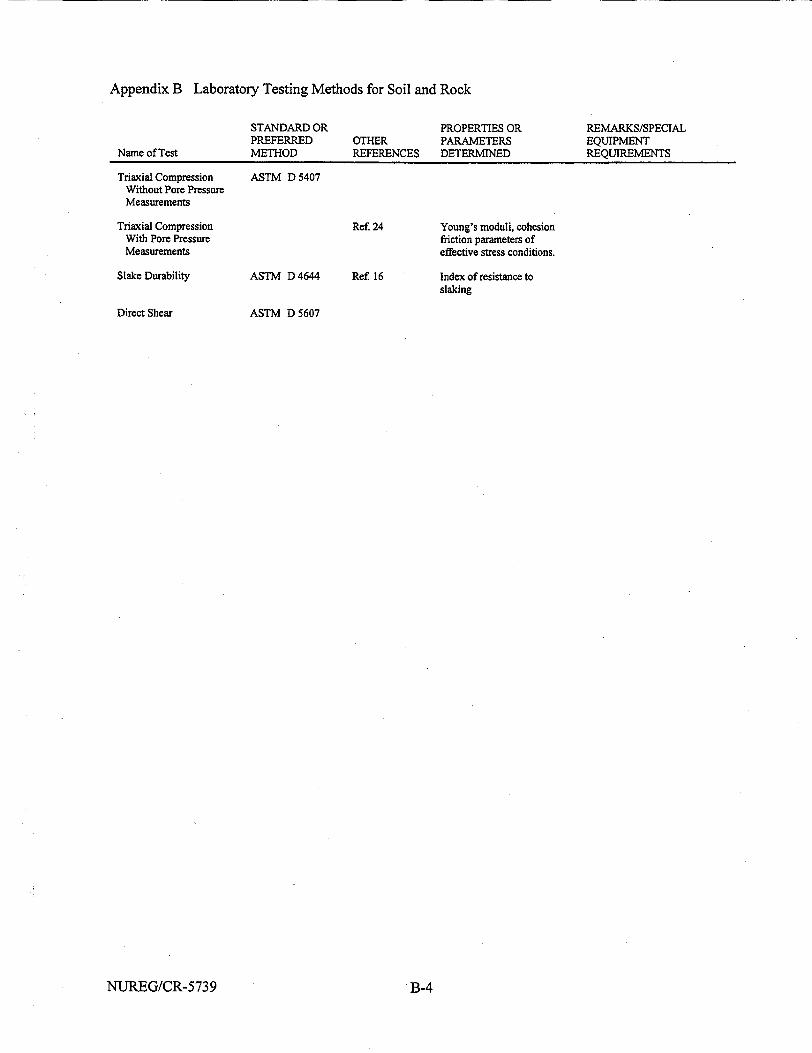
Appendix B Laboratory Testing Methods for Soil and Rock
STANDARD OR PREFERRED METHOD
OTHER REFERENCES
PROPERTIES OR PARAMETERS DETERMINED
REMARKS/SPECIAL EQUIPMENT REQUIREMENTS
Triaxial Compression Without Pore Pressure Measurements
Triaxial Compression With Pore Pressure Measurements
Slake Durability
Direct Shear
ASTM D 5407
ASTM D 4644
ASTM D 5607
Ref. 24
Ref 16
Young's moduli, cohesion friction parameters of effective stress conditions.
Index of resistance to slaking
NUREG/CR-5739
Name of Test
B-4

Appendix C Figures
APPENDIX C FIGURES .
NUREG/CR-5739C-1
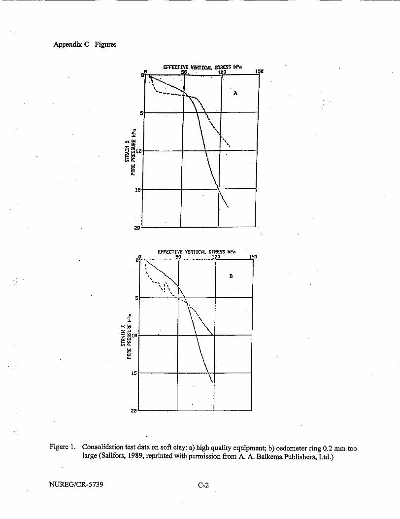
Appendix C Figures
to
a:
020
a:
EFFECTIVE VERTICAL STRESS kPo 5s 106 150
B
%' 9%
CC
&In I
cr, W
I- cc:
(L a: 0.
Figure 1. Consolidation test data on soft clay: a) high quality equipment; b) oedometer ring 0.2 mm too large (Sallfors, 1989, reprinted with permission from A. A. Balkema Publishers, Ltd.)
NUREG/CR-5739 C-2
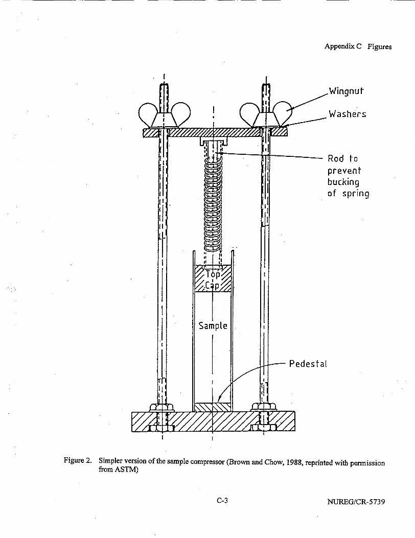
Appendix C Figures
.Wingnut
Washers
Rod to prevent bucking of spring
1A I X
S Sampte
It r
Pedestal
C I/
[ t
Figure 2. Simpler version of the sample compressor (Brown and Chow, 1988, reprinted with permission from ASTM)
NUREG/CR-5739
I
C-3
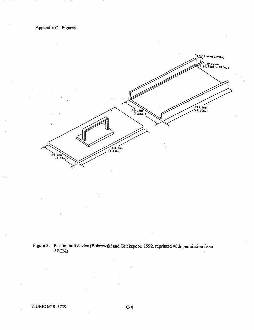
Appendix C Figures
Figure 3. Plastic limit device (Bobrowski and Griekspoor, 1992, reprinted with permission from ASTM)
NUREG/CR-5739 C-4
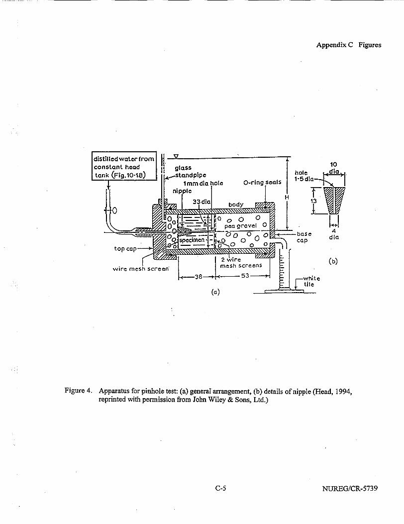
Appendix C Figures
Figure 4. Apparatus for pinhole test: (a) general arrangement, (b) details of nipple (Head, 1994, reprinted with permission from John Wiley & Sons, Ltd.)
NUREG/CR-5739C-5
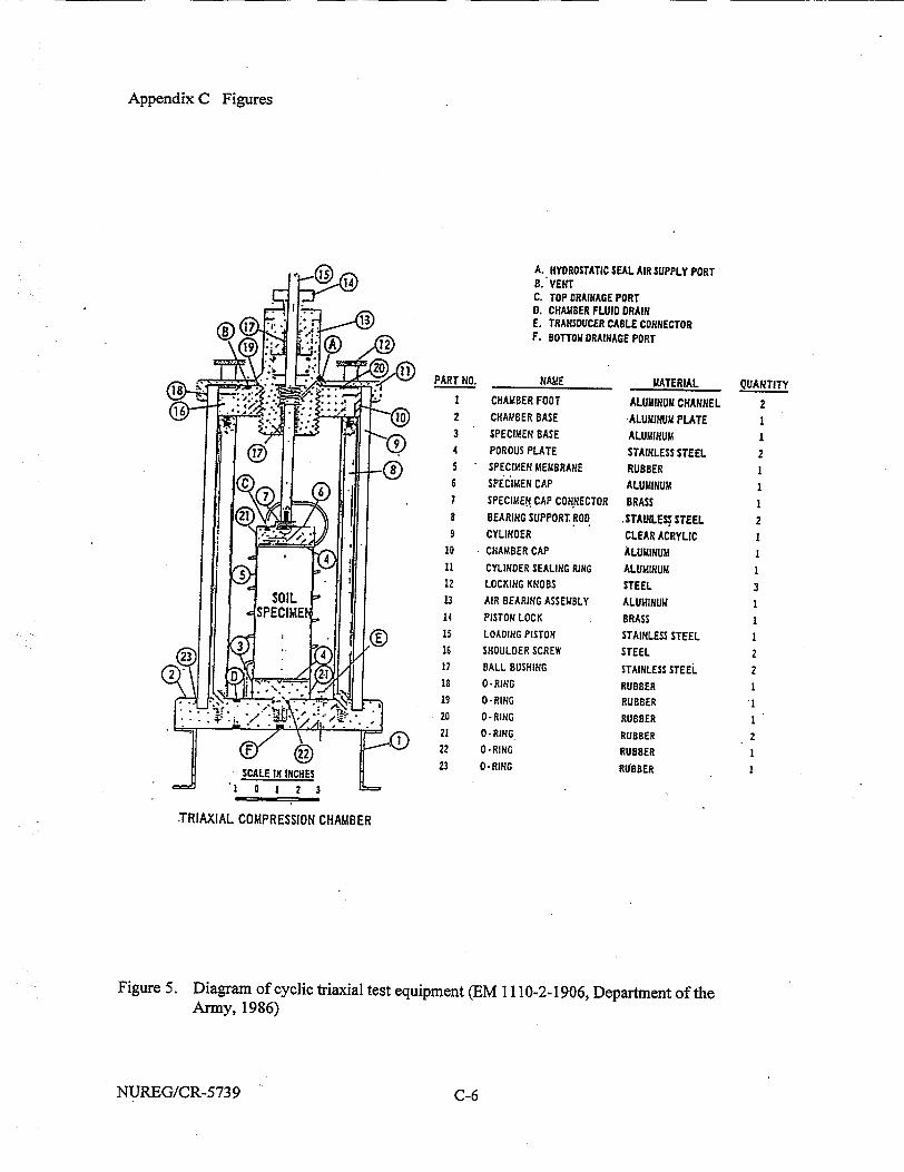
Appendix C Figures
1.5 A.. IHYDROSTATIC SEAL AIR SUPPLY PORT SB8. VENT"
C. TOP DRAINAGE PORT 0. CHAMBER FLUID DRAIN
13 E. TRANSDUCER CABLE CONNECTOR n A 2F. BOTTOM DRAINAGE PORT
... PART NO. NAME________ MATERIAL QUANTITY I CHAMBER FOOT ALUMINUM CHANNEL 2
16 2... 2 CHAMBER BASE -ALUMINUM PLATE I 3 SPECIMEN BASE ALUMINUM I
• 4 POROUS PLATE STAINLESS STEEL 2 * 5 SPECIMEN MEMBRANE RUBBER
6 6 SPECIMEN CAP ALUMINUM I 17 SPECIMEN CAP CONNECTOR BRASS I
8 BEARING SUPPORT ROD .STAINLES STEEL 2 9 CYLINDER CLEAR ACRYLIC I
10 - CHAMBER CAP ALUMINUM I 5 11 CYLINDER SEALING RING ALUMINUM 1
12 LOCKING KNOBS STEEL 3 SOIL 13 AIR BEARING ASSEMBLY ALUMINUM 1 SPECIME 14 PISTON LOCK BRASS I
E 15 LOADING PISTON STAINLESS STEEL 1 Ss16 SHOULDER SCREW STEEL 2
17 BALL BUSHING STAINLESS STEEL 2 18 O-RING RUBBER 1
19 O-RING RUBBER • '.20 O-RING RUBBER I
21 o-RING RUBBER 2 F '' 22 0-RING RUBBER 1
SCALEININCHES 23 O.NG RUB8ER S"! 0 I 2 3 =
TRIAXIAL COMPRESSION CHAMBER
Figure 5. Diagram of cyclic triaxial test equipment (EM 1110-2-1906, Department of the Army, 1986)
NUREG/CR-573 9 C-6
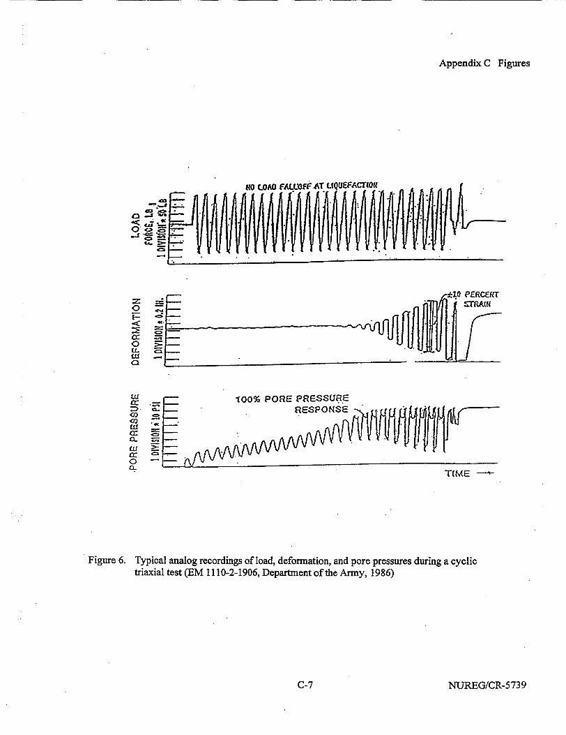
Appendix C Figures
"00% PORE PRESSUR.E
0'
-t
0
0 (I(.LI Co
LC 0,
LUf 02 03
Figure 6. Typical analog recordings of load, deformation, and pore pressures during a cyclic triaxial test (EM 1110-2-1906, Department of the Army, 1986)
NUREG/CR-5739
T(ME
a-
IV
C-7
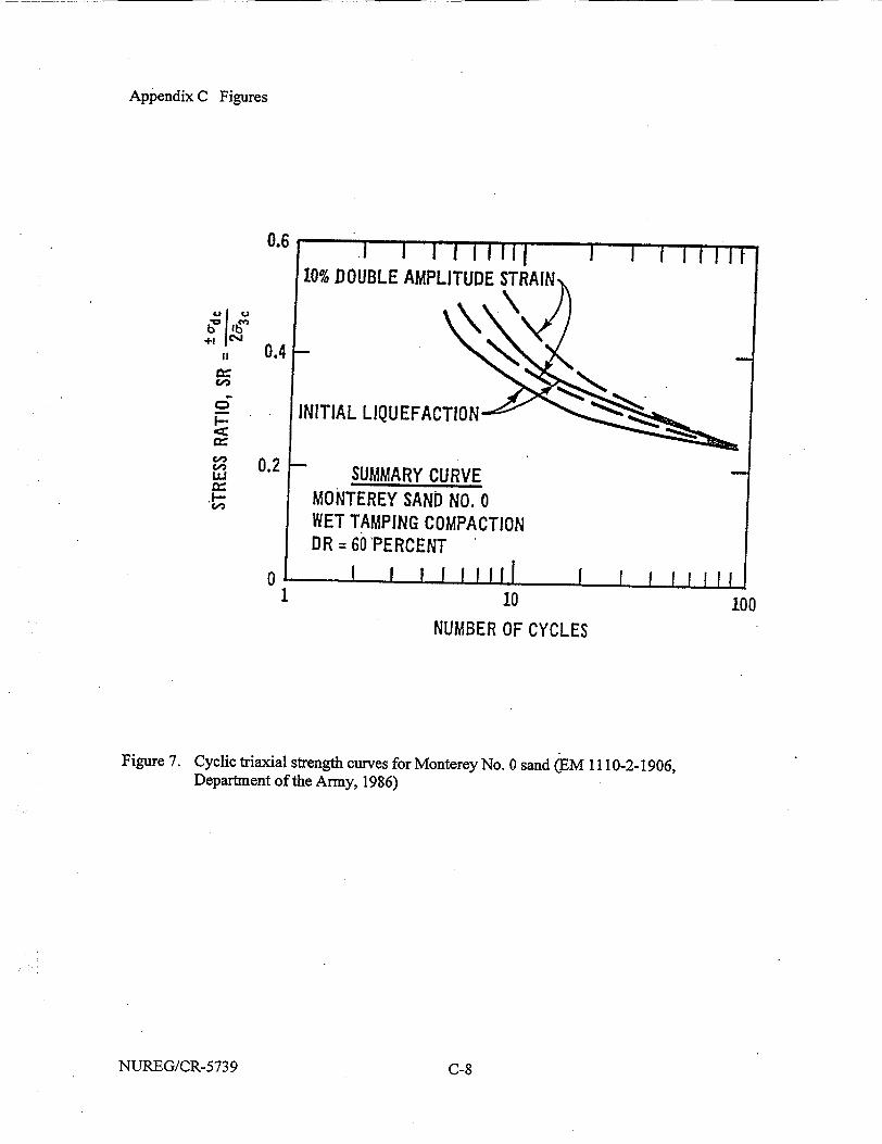
Appendix C Figures
0.6
+!
II
I-- *
0.4
0.2
01 10 100
NUMBER OF CYCLES
Figure 7. Cyclic triaxial strength curves for Monterey No. 0 sand (EM 1110-2-1906, Department of the Army, 1986)
NUREG/CR-5739 C-8
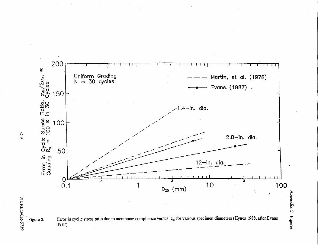
200
b
b.150 160 0
., 100 '-0
.0 &d 50
C
L
LiJO
0.1 1 D20 (mm) 10
C F) ,• Figure 8. L/1
"0
a
3."
'1 a Cd2
Error in cyclic stress ratio due to membrane compliance versus D20 for various specimen diameters (Hynes 1988, after Evans 1987)
"0
100
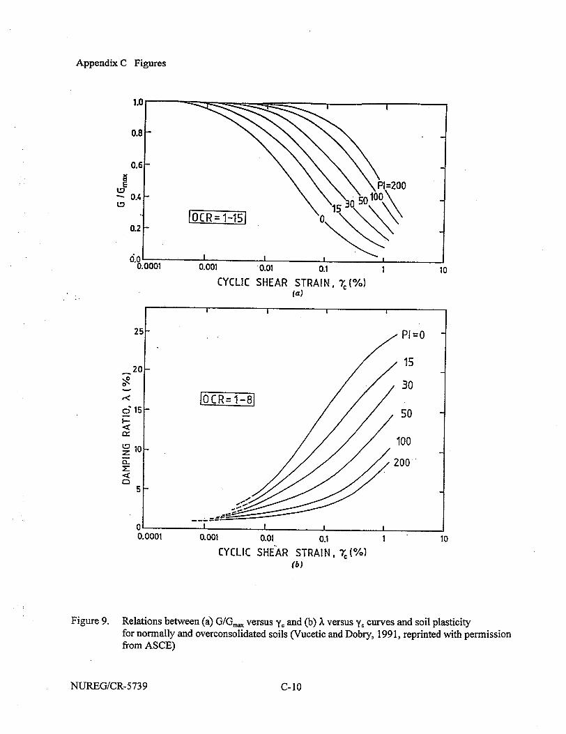
Appendix C Figures
E \\PI,=200 tv0.4 1505100P20
* OCR= 1-15 0 0.2
0''~.0 I , , 0.0001 0.001 0.01 0.1 1 10
CYCLIC SHEAR STRAIN, r(%) (a)
25- P1=O
15 20- 1
30 e< OCR=1-8 6515-E 50
100
a- 200
5
0 0.0001 0.001 0.01 0.1 1 10
CYCLIC SHEAR STRAIN, 71 (%) (b)
Figure 9. Relations between (a) GIG•, versus yr and (b) X versus y. curves and soil plasticity for normally and overconsolidated soils (Vucetic and Dobry, 1991, reprinted with permission from ASCE)
NUREG/CR-5739 C-10
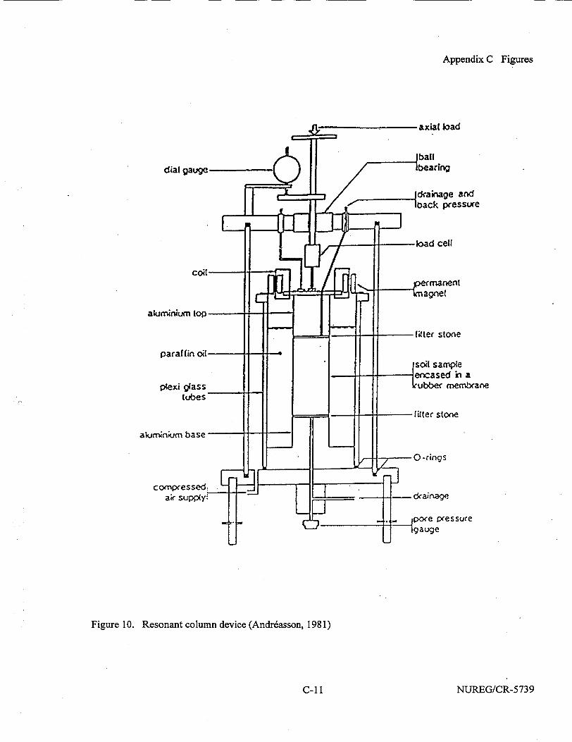
Appendix C Figures
Figure 10. Resonant column device (Andr~asson, 1981)
NUREG/CR-5739C-1 1
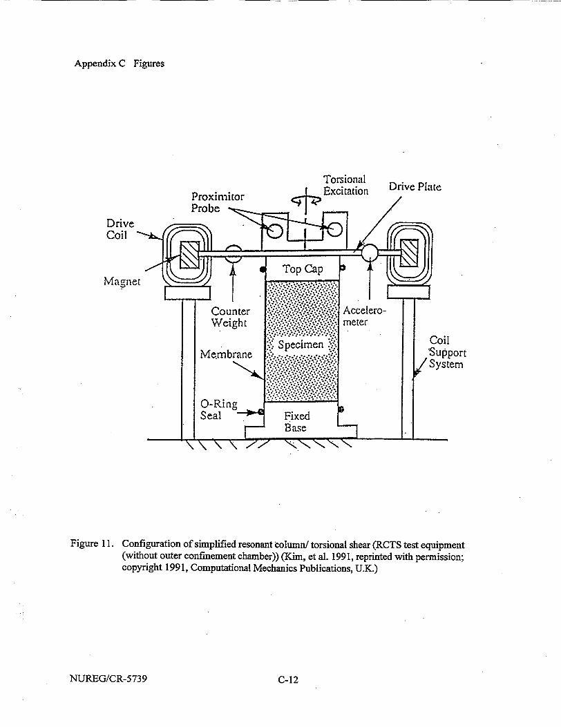
Appendix C Figures
Torsional Drive Plate Excitation D
Drive
e o Cap
Counter cero Weight , meter
Specimenoil Me.mbrane Support S: / System
Seal Fixed Base
Figure 11. Configuration of simplified resonant column/ torsional shear (RCTS test equipment (without outer confinement chamber)) (Kim, et al. 1991, reprinted with permission; copyright 1991, Computational Mechanics Publications, U.K.)
NUREG/CR-5739 C-12

Appendix C Figures
- = 0.70
6= 5 psi
O RC A TS- Ist o TS-10th f=O.5Hz + TS-after RC
I . . " I I I A" " ' ' r-T-T-r~
0
0 + 0 []
00
O n D
10 -2 to
ShearingStrain, Y, %
Figure 12. Variation in damping ratio with strain at different loading cycles (for dry sand) (Kim, et al., 199 1, reprinted with permission, copyright 199 1, Computational Mechanics Publications, U.K.)
15
0u
W
121
9
6
3
010
10 t 10 2
Number of Cycles
I
10
Figure 13. Variation in damping ratio with number of cycles (for dry sand) (Kim, et al., 1991, reprinted with permission, copyright 1991, Computational Mechanics Publications, U.K.)
NUREG/CR-5739
12
ca
6i
8
4
01o-0
Loading Frequency = 0.5 Hz,
ýO C1or--0.00lI% A 7=0.006%
o .- =0.014% ,
0 0 0 00
0 1h 0 13
!
C-13
Appendix D Tables
APPENDIX D TABLES
NUREG/CR-5739D-1
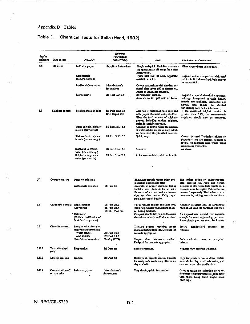
Appendix D Tables
Table 1. Chemical Tests for Soils (Head, 1992)
Reference
Seation CBS, blnpies reference 7Ype of test Procedure BS1377Th199 Uses Limijarlons and comunea
S.S pH value Indicator papers Supplier's instructions Simple and quick. Useful for determin- Gives approximate values only.
Colorimetric (Kuhn's method)
Lovibond Comparator
Electrometric
5.6 Sulphate content Total sulphates in soils
Water-soluble sulphates in soils (gravimetric)
Water-soluble sulphates in soils (ion exchange)
Sulphates in groundwater (ion exchange) Sulphates in groundwater (gravimetric)
Manufacture's instructions
BS Test Part 3:9
ing approximate pH range for a more sensitivetest. Quick field test for soils. Apparatus available as a kit.
Colour comparison with standard col. outed discs gives pH to nearest 0.2. Range of indicators available. BS 'standard' method. Accurate to 0.1 pH unit or better.
BS Part 3"5.2. 5.5 Accurate if performed with care and ERE Digest 250 with proper chemical testing facilities.
Gives the total amount of sulphates - presnt, including calcium sulphate,
which is insoluble in water. BS Part 3:5.3, 5.5 Accuracy as above. Gives the amount
of water-soluble sulphates only, which are those most likely to attack concrete.
BS Part 3.5.3, 5.6 Quick, easy
BS Part 3;5A, 5.6
ES Part 3:5.4,'5.5
As above.
As for water-soluble sulphates in soils.
Requires colour comparison with chait printed in British standard. Values given to nearest 0.5.
Requires a special electrical apparatus, although low-priced portable battery models are available. Electrodes age slowly, and should be checked periodically with buffer solutions.. If the mcasured 'sulphate content is greater than 0.5%. the water-soluble sulphates should also be measured.
Cannot be used if chloride, nitrate or phosphate ions are present. Requires a special ion-exchange resin which needs reactivating frequently. As above.
5.7 Organic content Peroxide oxidation
Dichromate oxidation
5.8 Carbonate content Rapid titration Gravimetrtic
* Calcimeter (Collin's modification of Schlciber's apparatus)
5.9 Chloride content Reaction with silver nitrate (Volhard's method):
Water soluble Acid soluble
Mohr's titration method
5.10.2 Total dissolved Evaporation solids
5.10.3 Loss on ignition Ignition
5.10.4 Conoentration of' Indicator papers ecrtain salts
Eliminates organic matter before sedi- Has limited action on undecomposed mentation particle size tests, plant remains (e.g. roots and fibres).
BS Part 3:3 Accurate, if proper chemical testing Presence ofchlorides affects results but a facilities used. Suitable for all soils, correction can be applied if chlorides are Presence of carbon and carbonates measured separately. Their eflect can be does not affect results. Fairly rapid, overcome by adding mercuric sulphate. suitable for small batches.
BS Part 3:6.3 For carbonate content exceeding 10% Accuracy no better than 1% carbonates BS Part 316.4 Requires precision weighing and chemi- Method as used for hardened concrete. BS1881: Part 124 cal testing facilities.
Compactsimple. faidyquick. Messures An approximate method, but accurate the volume of carbon dioxide evolved, enough for most engineering purposes.
ES Part 3:7.2 BS Part 3:7.3 Bowley (1979)
BS Part 3:8
BS Part 3:4
Manufacturer's :'instructions
Titration process requiring proper chemical testing facilities. Designed for concrete aggregates.
Simpler than Volhard's method. Designed for concrte aggregates.
Simple procedure.
Destroys all organic matter. Suitable for sandy soils containing little or no clay or chalk.
Very simple, quick. inexpensive.
Atmospheric pressure must be known.
Several standardised reagents are required
Both methods require an analytical balance.
Requires very accurate weighing.
High temperature breaks down certain minerals in clay, and "carbonates, .and removes water of crystallisation.
Gives approximate indication only; not for accurate work.'Prmscnc of salts other
•than those being tested might affect readings
NUREG/CR-5739 D-2

Appendix D Tables
- � *q*;Sn .- xflfl* �1 *$
a'J� -
* w..Tr.s - ,.�5:-r. .- .T:- y�.*. Cu:. ..E �% � 11.�J� �U 3.
*�=. .. w.i.a -. 3 �. �- 1.�* 3. .... ,.�,.( �wa�4
I
ii I I
"i
2
I 1
1k
.2
p -7-
I I
El II 2k
�= .t.tn,
2
11 I I
I
I
a
I
1� 1*
5'
p
I
1j
I
-t t - -t
I 1
2
I I
c.-u,. (.U3.
1- �*-tf - *fl@�
nt.:s.jUd - *tflfl) *Itfl�JUY2 - I .�.I � I *"��
S � £ � S S
'I I
A
I
I
111 I
I I
I.
-i .1*
I I
ii.
I
'I
A
I
si I e I
I A
I
I- MW &M V--ta
im_____ _______J_______L* rT I'f I1m w.
.n. -I.~ -n...adat*t ?... $I~ tt 210I
D-3 NUREG/CR-5739
a,
0)
ch
a, .2
0
0
7.
co co
cc, L) 0, (n
2.
51
P
A
E
I
A I
1;
IN
rt Ia .is I r
I
I
D-3
I
I
-n..Un.m
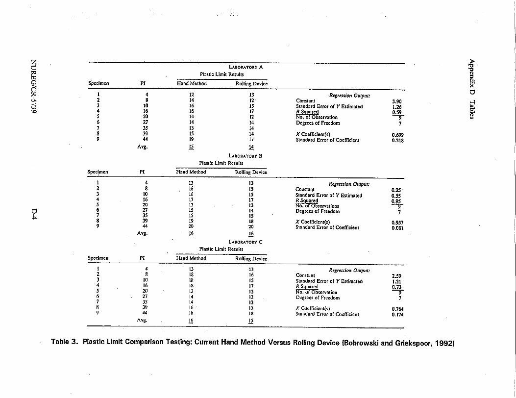
tI'
Table 3. Plastic Limit Comparison Testing: Current Hand Method Versus Rolling Device (Bobrowski and Griekspoor, 1992)
LABORATORY A
Plastic Limit Results
Specimen PI Hand Method Rolling Device
1 4 12 13 -Regression Output: 2 8 14 12 Constant 3.90 3 10 16 Is Standard Error of Y Estimated 1.26 4 16 16 17 E qured 0.59 5 20 14 12 No.6o bservation 6 27 14 14 Degrees of Freedom 7 7 35 13 14 8 39 15 14 X Coefficient(s) 0.699 9 44 19 17 Standard Error of Coefficient 0.218
Avg. 15 14
LABORATORY B Plastic Limit Results
Specimen PI Hand Method Rolling Device
1 4 13 13 Regression Output: 2 8 16 15 Constant 0.253 10 16 15 Standard Error of Y Estimated 0.55 4 16 17 17 R . 0.95 5 20 13 13 NO. of Observations 9 6 27 15 14 Degrees of Freedom 7 7 35 15 is 8 39 19 18 X Coefficient(s) 0.957 9 44 20 20 Standard Error of Coefficient 0.081
Avg. 16 16
LABORATORY C
Plastic Limit Results
Specimen PI Hand Method Rolling Device
'1 4 13 13 Regresslon Output: 2 8 18 16 Constant 2.59 3 10 18 is Standard Error of Y Estimated 1.21 4 16 I8 17 R Suarcd 0.73 5 20 12 13 No. of Observation 9 6 27 14 12 Degrees of Freedom 7 7 35 14 12 8 39 16 15 X Coefficicnt(s) 0.764 9 44 Ix I8 Standard Error of Coefficient 0.174
Avg. 16 15
,-
("
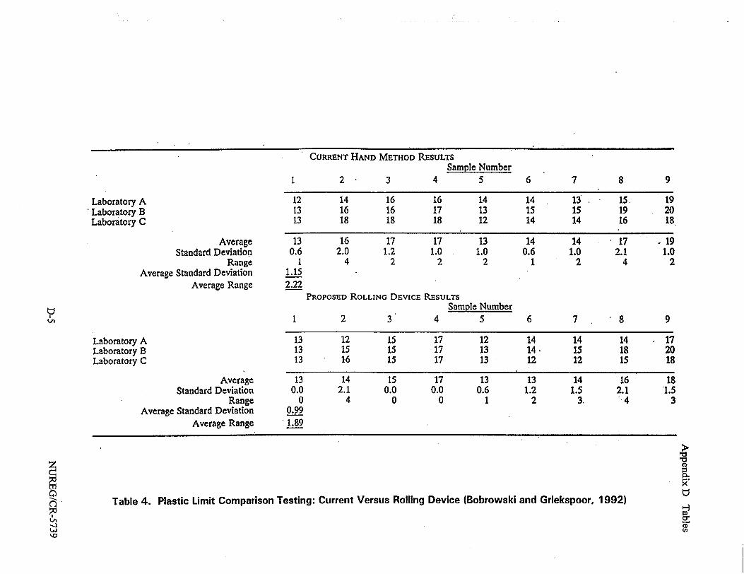
CURRENT HAND METHOD RESULTS
Sample Number 2 3 4 5
Laboratory A 'Laboratory B Laboratory C
Average Standard Deviation
Range Average Standard Deviation
Average Range
Laboratory A Laboratory B Laboratory C
Average Standard Deviation
Range Average Standard Deviation
Average Range
12 14 16 16 14 14 13 15. 19 13 16 16 17 13 15 15 19 20 13 18 18 18 12 14 14 16 18
13 16 17 17 13 14 14 17 19 0.6 2.0 1.2 1.0 1.0 0.6 1.0 2.1 1.0
1 4 2 2 2 1 2 4 2 1.15 2.22
PROPOSED ROLLING DEVICE RESULTS Sample Number
1 2 3 4 5 6 7 8 9
13 12 15 17 12 14 14 14 17 13 15 15 17 13 14. 15 18 20 13 16 15 17 13 12 12 15 18
13 0.0
0 0.99 1.89
14 2.1
4
15 0.0
0
17 0.0
0
13 0.6
1
13 1.2
2
14 1.5
3.
16 2.1 4
18 1.5
3
Table 4. Plastic Limit Comparison Testing: Current Versus Rolling Device (Bobrowski and Griekspoor, 1992)
'-3
1 6 7 8 9
0
'.0
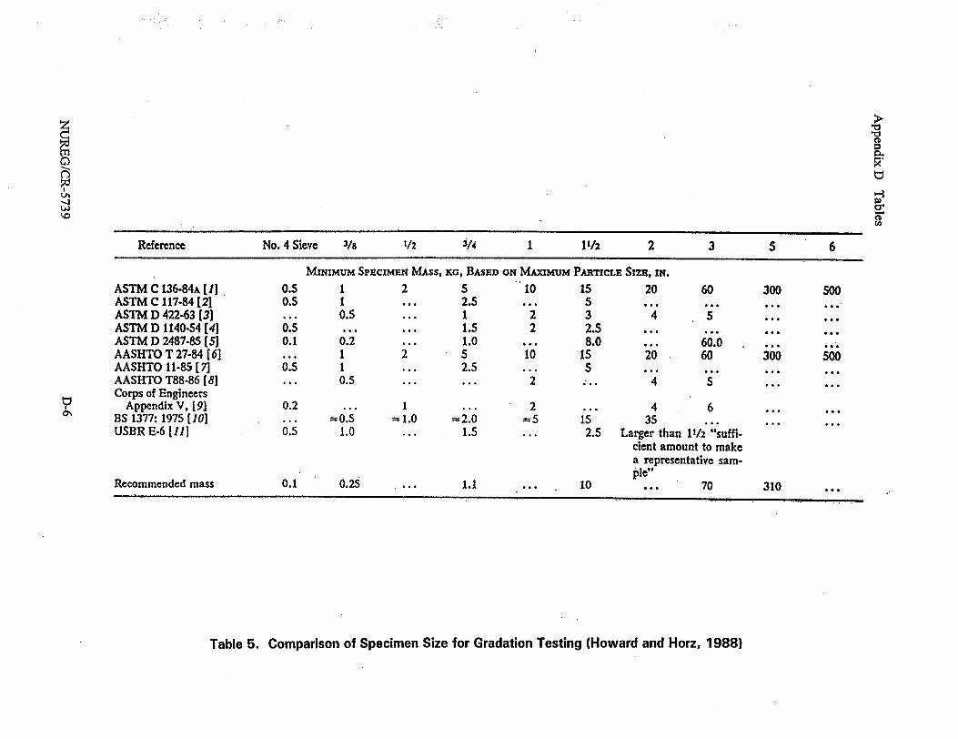
Reference No. 4 Sieve 3/8 1/2 S/4 1 l1/2 2 3 S 6
MINIMUM SPECIMEN MASS, KG, BASED ON MAXIMUM PARTICLE SIZE, IN.
ASTM C 136-84A [I] 0.5 1 2 5 10 15 20 60 300 500 ASTM C 117-84 [21 0.S I ... 2.5 ... 5 ASTM D 422-63 [3 ... 0.5 ... 1 2 3 4 5 .. ... ASTM D 1140-54 [41 0.5 ... ... 1.5 2 2.5 ... ASTM D 2487-85 (5) 0.1 0.2 ... 1.0 8.0 60.0 AASHTO T 27-84 [61 ... 1 2 5 10 15 20 60 300 500 AASHTO 11-85 [ 71 0.5 1 ... 2.5 ... ...... AASHTO T88-86 [81 ... 0.5 ... ... 2 ... 4 S Corps of Engineers
Appendix V, [91 0.2 ... 1 2 ... 4 6 ... BS 1377: 1975 1101 ... -0.5 -1.0 2.0 %= •5 i5 35 ...... USBR E-6 [11] 0.5 1.0 ... 1.5 ... 2.5 Larger than 11/ 2 "suffi
cient amount to make a representative sample"
Recommended mass 0.1 0.25 ... 1.1 ... 10 ... 70 310 ...
Table 5. Comparison of Specimen Size for Gradation Testing (Howard and Horz, 1988)
'0 '0
0.
H a. 0
0%
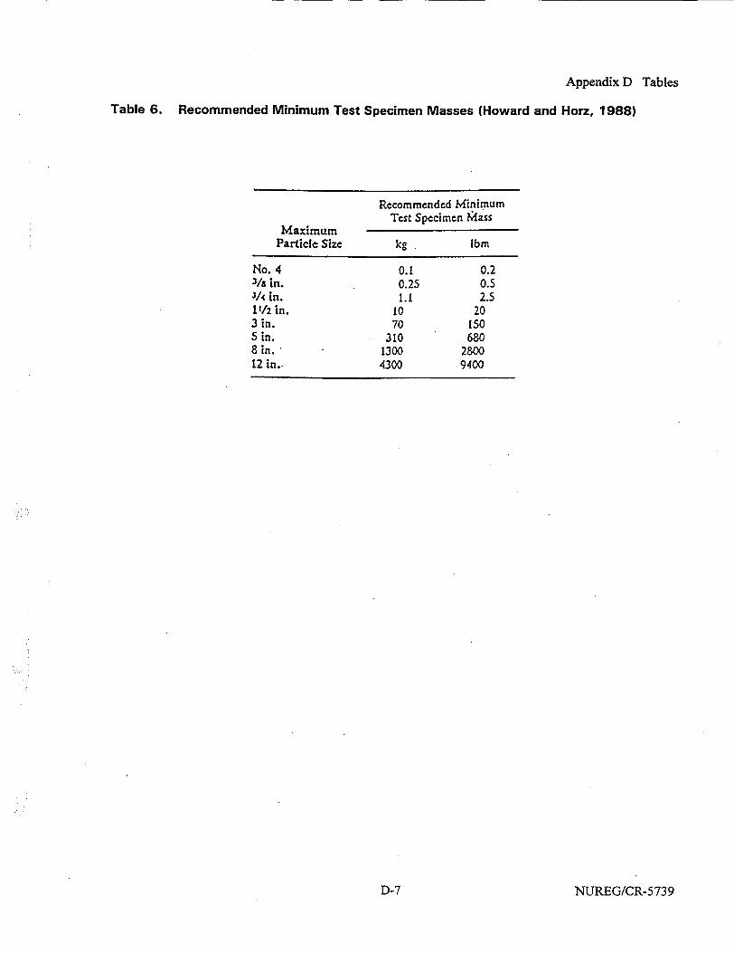
Appendix D Tables
Table 6. Recommended Minimum Test Specimen Masses (Howard and Horz, 1988)
Recommended Minimum Tcst Specimen Mass
Maximum Particle Size kg Ibm
No. 4 0.1 0.2 31a in. 0.25 0.5 3/4 in. 1I. 2.5 11/2 in. 10 20 3 in. 70 IS0 S in. 310 680 8 in. 1300 2800 12 in., 4300 9400
NUREG/CR-5739D-7

NRC FORM 335 U.S NUCLEAR REGULATORY COMMISSION 1. REPORT NUMBER (24M) (Assigned by NRC, Add VoL, Supp., Rev., NRCM11OZ and Addendum Numbers. If any.) 3201, 3202 BIBUOGRAPHIC DATA SHEET
(See inssfuctions on am evewS)
2. TITLE AND SUBTITLE NUREG/CR-5739
Laboratory Investigations of Soils and Rocks for Engineering Analysis and Design of Nuclear Power Facirities 3. DATE REPORT PUBLSHED
MONTH .YEAR
January 2000 4. FIN OR GRANT NUMBER
W6453 5. AUTHOR(S) 6. TYPE OF REPORT
T. Holmes, J. P. Koester Technical
7. PERIOD COVERED ilndusive Dates)
June 1995-July 1999
8. PERFORMING ORGANIZATION - NAME AND ADDRESS (If NRC, provide Division, Office orRegi&, U.S. NudeerReguiasty Commission, and mailing address,; if conhtctor, provide name and mailing addess.)
U.S. Army Corps of Engineers Waterways Experiment Station 3909 Halls Ferry Road Vicksburg, MS 39180-6199
9. SPONSORING ORGANIZATION - NAME AND ADDRESS (ff NRC, tye "Same as above', if confcobr, provide RCDivision, Office rRegion, U.S. Nuclear Regulatory Commission, and mailing address.)
Division of Engineering Technology Office of Nuclear Regulatory Research U.S. Nuclear Regulatory Commission Washington, DC 20555-0001
10. SUPPLEMENTARY NOTES
E. G. Zurflueh, NRC Project Manager 11. ABSTRACT (r00 wods orsA)
This document provides technical bases for revision of the U.S. Nuclear Regulatory Commission Regulatory Guide 1.138, Laboratory Investigations of Soils for Engineering Analysis and Design of Nuclear Power Plants, reflecting current and state-of-the-art techniques related to laboratory testing of soils. This report summarizes the processes required in a laboratory testing program. Topics range from storage, selection, and handling of test specimens, to static and dynamic testing methods and equipment. Specific requirements for liquefaction analysis and field site investigations are not addressed in this document but are covered in companion technical bases documents.
12. KEY WORDS/DESCRIPTORS (List woads aorpvses that wil assist researchers in ocating te report) 13. AVAILABIUTY STATEMENT
Static and Dynamic Testing unlimited
Sample Preparation 14. SECURITY CLASSIFICATION
(This Page)
unclassified (This Repot)
unclassified 15. NUMBER OF PAGES
16. PRICE
NRC ORM3382.89 Ths ltin as lecroniall prduce byElie Feera FomsinCNRC FORM 335 (2-W9) This form wa electronically produced by Elite Federal Forms, Inc.