Embed Size (px)
Citation preview

LABOROTA 4000/4001 efficientLABOROTA 4010/4011 digital LABOROTA 4002/4003 control LABOROTA 4002/4003 control
vario
Betriebsanleitung Instruction manual
Mode d’Emploi Manual de
Instrucciones Istruzioni per l‘uso

2
IDI DEUTSCH Seite 3 – 55
IEI ENGLISH page 56 – 106
IFi FRANCAISE page 107 – 159
lESI ESPAÑOL página 160 – 213
lIIIl ITALIANO Pagina 214 - 267

56
E Thank you for purchasing a Heidolph Instruments product. This item has been designed, made and inspected in compliance with DIN EN ISO 61010 for long performance and continuous operation.
SUMMARY
SUMMARY ........................................................................................................................56 STANDARD ITEM PLUS OPTIONS .................................................................................59 GENERAL .........................................................................................................................60 SAFETY INFORMATION ..................................................................................................60 SET-UP..............................................................................................................................62
1. Item set-up .................................................................................................................. 62 2. Electric wiring .............................................................................................................. 63 2.1. Bayonet-type plug connector ....................................................................................... 63 3. Install condenser support bar, when using G3, G4, G5 and G6 glassware kits ........... 64 4. Install vapor tube ........................................................................................................ 64 5. Install glassware set G1 .............................................................................................. 65 6. Install glassware set G3 .............................................................................................. 67 7. Install glassware set G4 .............................................................................................. 68 8. Install glassware set G5 .............................................................................................. 69 9. Install glassware set G6 .............................................................................................. 71 9.1. Adjust vacuum pressure tightness of valve (E) of G6 glassware kit............................. 72 10. Cooling water fitting on glassware kit .......................................................................... 73 11. Connect vacuum pressure to glassware kit ................................................................. 73 12. Install Woulff flask / vacuum valve................................................................................ 73 13. Vacuum lines................................................................................................................ 74 13.1. LABOROTA 4000/4001 efficient, LABOROTA 4010/4011 digital................................. 71 13.2. LABOROTA 4002/4003 control with Rotavac valve control ......................................... 72 13.3. LABOROTA 4002/4003 control with Rotavac vario control .......................................... 73 14. Install protective hood .................................................................................................. 77 15. Install protective shield ................................................................................................. 77 16. Install boil temperature sensor for LABOROTA 4002/ 4003 control and LABOROTA
4010/4011 digital .......................................................................................................... 78 17. Install T auto temperature sensor ................................................................................ 78 18. Install remote control for LABOROTA 4001 efficient, 4011 digital and 4003 control)... 79 19. Connect VAC senso T with LABOROTA 4002/4003 control ........................................ 80 20. Connect ROTAVAC vario control power supply .......................................................... 81
CONTROLS AND OPERATION........................................................................................82 21. Adjust evaporator flask angle ....................................................................................... 82 22. Use of hand lift (LABOROTA 4000 efficient, 4010 digital and 4002 control) ................ 82 23. Use of power lift (LABOROTA 4001 efficient, 4011 digital and 4003 control) .............. 83 24. Adjust immersion depth of evaporator flask ................................................................ 83 25. Evaporator flask draw-off fixture................................................................................... 84 26. Displace heating bath .................................................................................................. 84 27. Fill hot bath .................................................................................................................. 85 28. Work with protective hood and protective shield ......................................................... 86

57
E29. Add substance to be distilled........................................................................................ 86 30. Aerate by hand ............................................................................................................. 86 31. Adjust hot bath temperature ......................................................................................... 86 31.1. LABOROTA 4000 / 4001 efficient and LABOROTA 4010 / 4011 digital....................... 86 31.2. LABOROTA 4002 / 4003 control .................................................................................. 88 32. Turn on and set rotary speed ....................................................................................... 88 32.1. LABOROTA 4000 / 4001 efficient................................................................................. 89 32.2. LABOROTA 4010 / 4011 digital.................................................................................... 89 32.3. LABOROTA 4002 / 4003 control .................................................................................. 89 33. Determine boil temperature with (optional) boil temperature sensor............................ 89 33.1. LABOROTA 4010 / 4011 digital.................................................................................... 89 33.2 LABOROTA 4002 / 4003 control .................................................................................. 90 34. Distillation control with LABOROTA 4002 / 4003 control.............................................. 90 34.1. General information...................................................................................................... 90 34.2. Display and edit values ................................................................................................ 90 34.3. Activate / deactivate vacuum control ............................................................................ 91 34.4. Select vacuum control mode ........................................................................................ 91 34.4.1. p const, settings ........................................................................................................... 91 34.4.2 T auto, settings............................................................................................................. 92 34.4.3. p auto, settings ............................................................................................................. 93 34.5. Timer function............................................................................................................... 93 34.5.1. TIME COUNTING:........................................................................................................ 93 34.5.2. TIMER: ......................................................................................................................... 93 34.5.3. Time display ................................................................................................................. 94 34.6. Discontinue evacuation ................................................................................................ 94 34.7. Save actual p const as nominal value .......................................................................... 94 34.8. Save and recall distillation parameters......................................................................... 94 34.8.1. Save file........................................................................................................................ 94 34.8.2. Recall file...................................................................................................................... 95 34.9. Auto Start Stop function ............................................................................................... 95 34.10. Pressure ramp: program, activate, save, and recall from memory............................... 95 34.10.1. Program and activate pressure ramp ........................................................................... 95 34.10.2. Save pressure ramp ..................................................................................................... 96 34.10.3 Recall pressure ramp from memory ............................................................................. 96 34.10.4. Program more pressure ramps..................................................................................... 96 34.10.5. Edit pressure ramps ..................................................................................................... 96 34.11. Calibrate pressure sensor ............................................................................................ 96 34.12. Safety switch-off in case of excessive pressure........................................................... 96
INFORMATION ABOUT DISTILLATION SETTINGS .......................................................97 35. Rotary speed of evaporator flask.................................................................................. 97 36. Temperature difference between hot bath and vapor................................................... 97 37. Temperature difference between vapor temperature and coolant................................ 97 38. Choose vacuum regulation mode and do respective settings ...................................... 97 38.1. p const vacuum regulating mode.................................................................................. 97 38.1.1. Settings in "p const" vacuum regulation mode ............................................................. 97
58
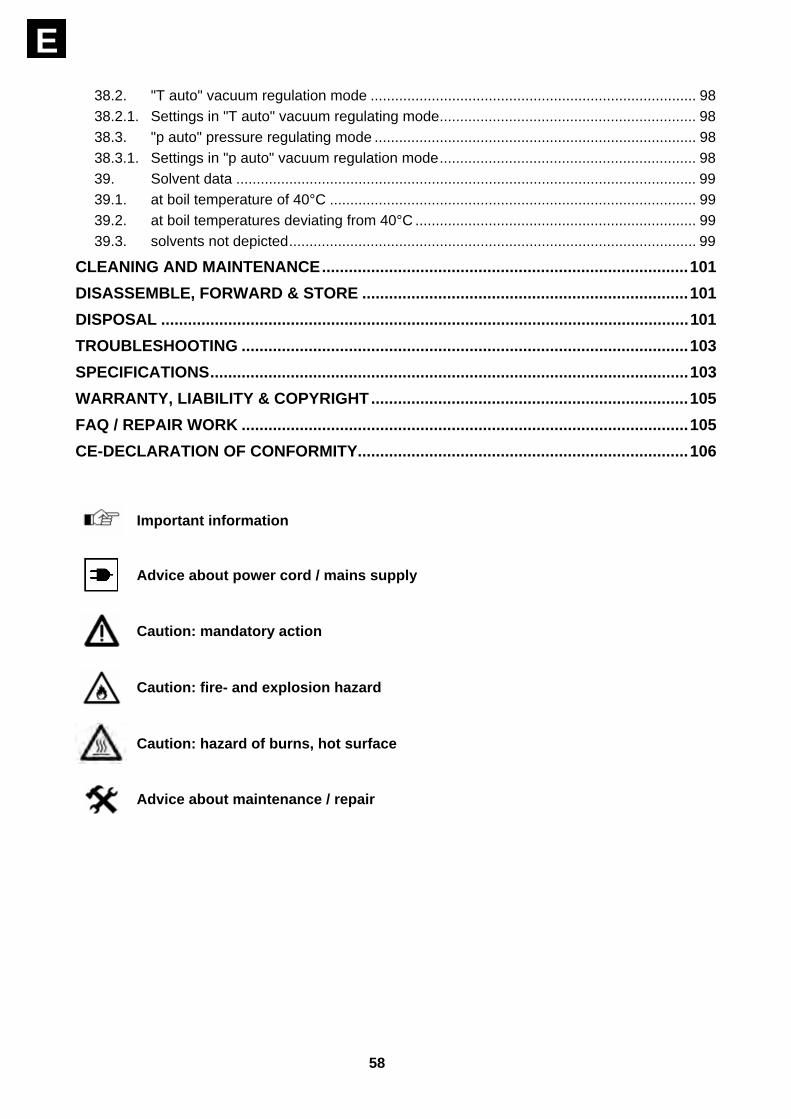
E 38.2. "T auto" vacuum regulation mode ................................................................................ 98 38.2.1. Settings in "T auto" vacuum regulating mode............................................................... 98 38.3. "p auto" pressure regulating mode ............................................................................... 98 38.3.1. Settings in "p auto" vacuum regulation mode............................................................... 98 39. Solvent data ................................................................................................................. 99 39.1. at boil temperature of 40°C .......................................................................................... 99 39.2. at boil temperatures deviating from 40°C ..................................................................... 99 39.3. solvents not depicted.................................................................................................... 99
CLEANING AND MAINTENANCE..................................................................................101 DISASSEMBLE, FORWARD & STORE .........................................................................101 DISPOSAL ......................................................................................................................101 TROUBLESHOOTING ....................................................................................................103 SPECIFICATIONS...........................................................................................................103 WARRANTY, LIABILITY & COPYRIGHT.......................................................................105 FAQ / REPAIR WORK ....................................................................................................105 CE-DECLARATION OF CONFORMITY..........................................................................106
Important information
Advice about power cord / mains supply
Caution: mandatory action
Caution: fire- and explosion hazard
Caution: hazard of burns, hot surface
Advice about maintenance / repair

59
E
STANDARD ITEM PLUS OPTIONS
item qty. P/N 230/240V 50/60Hz
P/N 115V 50/60Hz
basic item LABOROTA 4000 efficient 1 519-00000-00 519-00000-01 or basic item LABOROTA 4001 efficient 1 519-10000-00 519-10000-01 or basic item LABOROTA 4010 digital 1 519-40000-00 519-40000-01 or basic item LABOROTA 4011 digital 1 519-50000-00 519-50000-01 or basic item LABOROTA 4002 control 1 519-20000-00 519-20000-01 or basic item LABOROTA 4003 control 1 519-30000-00 519-30000-01 heating bath 4000 digit 1 517-01002-00 517-01002-01 or heating bath 4000 control 1 517-01001-00 517-01001-01 glass set G1 1 513-00100-00 513-00100-00 or glass set G3 1 513-00300-00 513-00300-00 or glass set G4 1 513-00400-00 513-00400-00 or glass set G5 1 513-00500-00 513-00500-00 or glass set G6 1 513-00600-00 513-00600-00 or glass set G1 coated 1 513-00110-00 513-00110-00 or glass set G3 coated 1 513-00310-00 513-00310-00 or glass set G4 coated 1 513-00410-00 513-00410-00 or glass set G5 coated 1 513-00510-00 513-00510-00 or glass set G6 coated 1 513-00610-00 513-00610-00 loose parts: coupling 1 23-09-03-01-03 23-09-03-01-03 cocking spring 1 22-03-02-01-05 22-03-02-01-05 PTFE 26 seal 1 23-30-01-01-30 23-30-01-01-30 clamping sleeve 26 1 23-30-01-02-89 23-30-01-02-89 coupling ring, vapor tube 1 11-300-005-19 11-300-005-19 power cord 1 14-007-003-81 14-007-045-10 link wire to heating bath 1 14-007-045-08 14-300-009-28
link wire to heatingt bath (LABOROTA 4002/4003 only) 1 14-300-003-36 14-300-003-36
Owner's Manual 1 01-005-004-24 01-005-004-24 Accessories
item P/N 230/240V 50/60Hz
P/N 115V 50/60Hz
protective hood 591-00010-00 protective shield 591-00020-00 boil temperature sensor 591-00030-00 temperature sensor T auto 591-00040-00 remote control 591-00050-00 extension panels 591-00090-00 ROTAVAC vacuum pump 591-00100-00 591-00100-01 ROTAVAC valve control vacuum pump 591-00130-00 591-00130-01 ROTAVAC vario control vacuum pump 591-00140-00 591-00140-01 VAC senso T 591-00350-00 591-00350-01 VAC control automatic vacuum controller 591-00340-00 591-00340-01 vacuum switchbox for 3 ea. separate items 591-00400-00 591-00400-01 Woulff-flask 591-00071-00 vacuum valve 591-24000-00 condensate cooler for ROTAVAC valve control 591-00081-00 condensate cooler for ROTAVAC vario control 591-00082-00 5 liters bath liquid 515-31000-00

60
E
GENERAL
Unpack your item carefully. Inspect for damage and report such damage or missing parts to your supplier immediately.
Read your Instruction Manual carefully. Take the time to read the manual which will save time while working with your product. Make sure that every user has read and understood the Instruction Manual.
Please store the Instruction Manual in a place easily accessible to every user.
IF ALL ELSE FAILS, READ THESE INSTRUCTIONS !
A so-called EURO-plug (DIN 49441 CEE 7/VII 10/ 16 A 250 V) is standard on all of the products. For the Continental US they feature a US-standard plug (NEMA Pub.No.WDI.1961 ASA C 73.1 . 1961 page 8 15A 125V). For using the item in a country with deviating outlet / plug systems, we recommend to use approved adapters or to have an electrician replace the standard plug with one mating your local system. As shipped, the item features a protective ground wire. When replacing the original plug, make sure to reconnect this protective ground wire in the new plug !
SAFETY INFORMATION
Please comply with all safety and accident prevention regulations as in force for laboratory work !
Use extra care while working with rotary evaporators.
Use eye protection and adequate clothing.
Use extra care while working with flammable substances; refer to safety data sheets.
Use extra care while working close to flammable and explosive substances. Motors are of non-sparking type, the item itself is not explosion-protected.
Before connecting your item with the local power supply, make sure the item has been designed for your local voltage; refer to data plate on item.
Connect your item with a grounded outlet only.
Turn power switch to OFF when item is not in use, or before disconnecting from mains.

61
E
Caution ! Hazard of burns when running the hot bath at temperatures exceeding 60°C. Avoid touching hot edge of bowl, evaporator flask and fluid in bowl. Use gloves when replacing evaporator flask.
Never run hot bath dry.
Repair work is limited to skilled personnel so authorized by Heidolph.
Your item needs a solid stand.
Locate the rotary evaporator on a smooth, horizontal table or on the ROTACOOL reflux cooler. Make sure not to obstruct area around evaporator.
Avoid overpressure in the system. Explosion hazard. For reasons of safety open aerating valve, when working at ambient pressure, in order to avoid excessive overpressure.
62
E
SET-UP
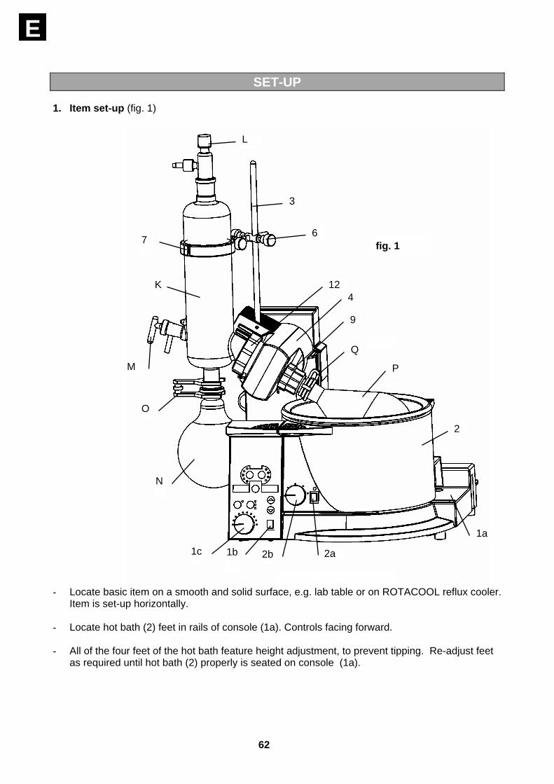
1. Item set-up (fig. 1)
- Locate basic item on a smooth and solid surface, e.g. lab table or on ROTACOOL reflux cooler. Item is set-up horizontally.
- Locate hot bath (2) feet in rails of console (1a). Controls facing forward.
- All of the four feet of the hot bath feature height adjustment, to prevent tipping. Re-adjust feet as required until hot bath (2) properly is seated on console (1a).
L
3
6 7
K
M
O
N
1c 1b 2b 2a
1a
2
P
Q
9
412
fig. 1
63
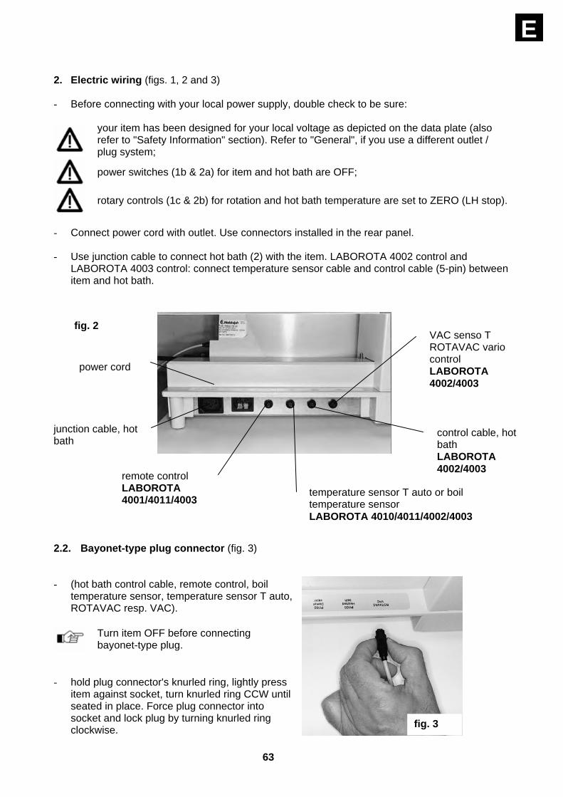
E 2. Electric wiring (figs. 1, 2 and 3) - Before connecting with your local power supply, double check to be sure:
your item has been designed for your local voltage as depicted on the data plate (also refer to "Safety Information" section). Refer to "General", if you use a different outlet / plug system;
power switches (1b & 2a) for item and hot bath are OFF;
rotary controls (1c & 2b) for rotation and hot bath temperature are set to ZERO (LH stop).
- Connect power cord with outlet. Use connectors installed in the rear panel.
- Use junction cable to connect hot bath (2) with the item. LABOROTA 4002 control and
LABOROTA 4003 control: connect temperature sensor cable and control cable (5-pin) between item and hot bath.
2.2. Bayonet-type plug connector (fig. 3) - (hot bath control cable, remote control, boil
temperature sensor, temperature sensor T auto, ROTAVAC resp. VAC).
Turn item OFF before connecting bayonet-type plug.
- hold plug connector's knurled ring, lightly press
item against socket, turn knurled ring CCW until seated in place. Force plug connector into socket and lock plug by turning knurled ring clockwise.
fig. 3
VAC senso T ROTAVAC vario control LABOROTA 4002/4003
power cord
junction cable, hot bath
remote control LABOROTA 4001/4011/4003
fig. 2
control cable, hot bath LABOROTA 4002/4003
temperature sensor T auto or boil temperature sensor LABOROTA 4010/4011/4002/4003

64
E
3. Install condenser support bar, when using G3, G4, G5 and G6 glassware kits
(refer to figs. 1 & 4) - G3, G4, G5 and G6 glassware kits are protected against tipping with condenser support bar.
- First secure bar (3) in threaded hole (4) with
hex-key screw (5). Tilt bar (3) to fit the condenser (K) to be held.
- Fit cross sleeve (6) on bar (3) and secure with clamp screw.
- Plug condenser clamp (7) in cross hole of cross sleeve (6) and secure with clamp screw.
4. Install vapor tube (refer to figs. 1,5,6,7 & 8 ) - The vapor tube ass'y. (8) is packed with the glassware kit. First remove coupling ring from
flange (12), remove cocking spring (13) and PTFE-seal (11), unthread vapor tube coupling ring (9) from drive (4) and remove clamping sleeve (10) by pulling.
- Slip coupling ring (9) and clamping sleeve (10) on vapor tube (8), bead pointing forward.
23 fig. 5
11 8 10
9 24
fig. 6
fig. 7
3
4
5
fig. 4
65
E
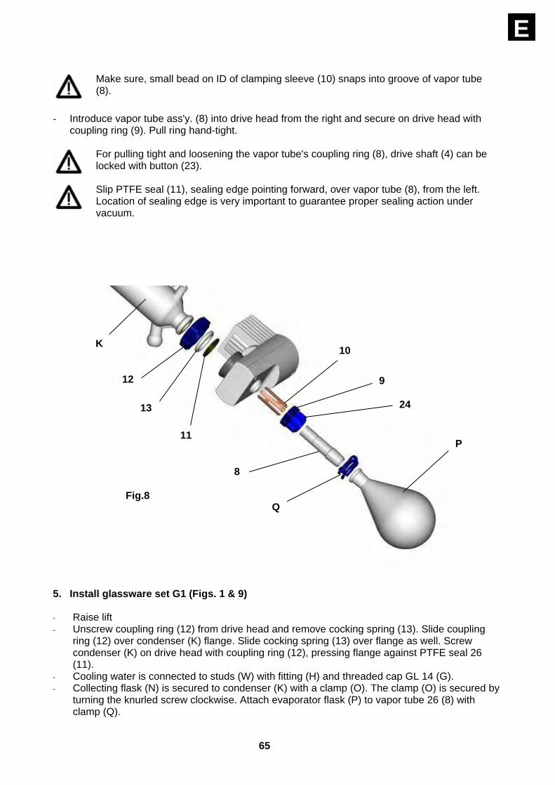
Make sure, small bead on ID of clamping sleeve (10) snaps into groove of vapor tube (8).
- Introduce vapor tube ass'y. (8) into drive head from the right and secure on drive head with
coupling ring (9). Pull ring hand-tight.
For pulling tight and loosening the vapor tube's coupling ring (8), drive shaft (4) can be locked with button (23).
Slip PTFE seal (11), sealing edge pointing forward, over vapor tube (8), from the left. Location of sealing edge is very important to guarantee proper sealing action under vacuum.
5. Install glassware set G1 (Figs. 1 & 9) - Raise lift - Unscrew coupling ring (12) from drive head and remove cocking spring (13). Slide coupling
ring (12) over condenser (K) flange. Slide cocking spring (13) over flange as well. Screw condenser (K) on drive head with coupling ring (12), pressing flange against PTFE seal 26 (11).
- Cooling water is connected to studs (W) with fitting (H) and threaded cap GL 14 (G). - Collecting flask (N) is secured to condenser (K) with a clamp (O). The clamp (O) is secured by
turning the knurled screw clockwise. Attach evaporator flask (P) to vapor tube 26 (8) with clamp (Q).
10
9
24
8
Q
P11
13
12
K
Fig.8
66
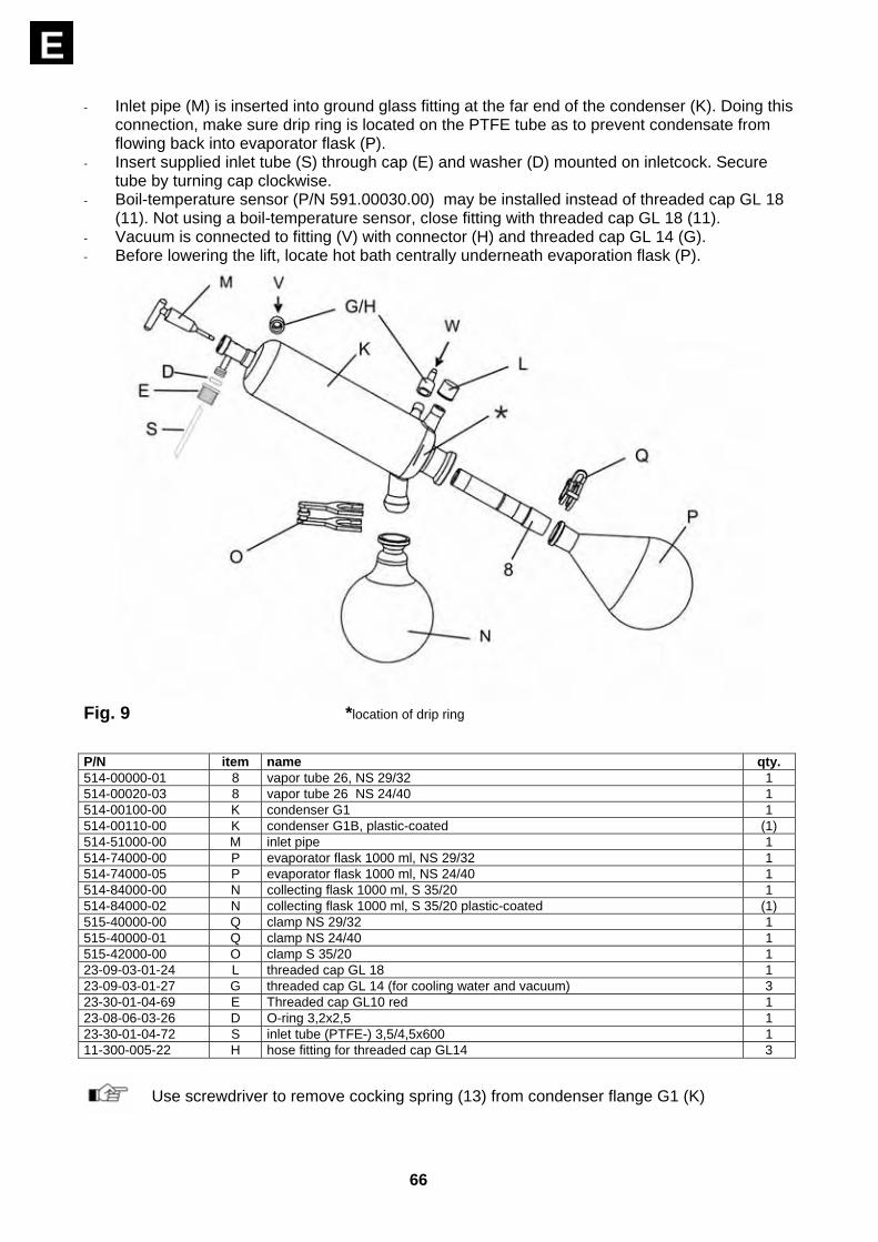
E - Inlet pipe (M) is inserted into ground glass fitting at the far end of the condenser (K). Doing this
connection, make sure drip ring is located on the PTFE tube as to prevent condensate from flowing back into evaporator flask (P).
- Insert supplied inlet tube (S) through cap (E) and washer (D) mounted on inletcock. Secure tube by turning cap clockwise.
- Boil-temperature sensor (P/N 591.00030.00) may be installed instead of threaded cap GL 18 (11). Not using a boil-temperature sensor, close fitting with threaded cap GL 18 (11).
- Vacuum is connected to fitting (V) with connector (H) and threaded cap GL 14 (G). - Before lowering the lift, locate hot bath centrally underneath evaporation flask (P).
Fig. 9 *location of drip ring P/N item name qty. 514-00000-01 8 vapor tube 26, NS 29/32 1 514-00020-03 8 vapor tube 26 NS 24/40 1 514-00100-00 K condenser G1 1 514-00110-00 K condenser G1B, plastic-coated (1) 514-51000-00 M inlet pipe 1 514-74000-00 P evaporator flask 1000 ml, NS 29/32 1 514-74000-05 P evaporator flask 1000 ml, NS 24/40 1 514-84000-00 N collecting flask 1000 ml, S 35/20 1 514-84000-02 N collecting flask 1000 ml, S 35/20 plastic-coated (1) 515-40000-00 Q clamp NS 29/32 1 515-40000-01 Q clamp NS 24/40 1 515-42000-00 O clamp S 35/20 1 23-09-03-01-24 L threaded cap GL 18 1 23-09-03-01-27 G threaded cap GL 14 (for cooling water and vacuum) 3 23-30-01-04-69 E Threaded cap GL10 red 1 23-08-06-03-26 D O-ring 3,2x2,5 1 23-30-01-04-72 S inlet tube (PTFE-) 3,5/4,5x600 1 11-300-005-22 H hose fitting for threaded cap GL14 3
Use screwdriver to remove cocking spring (13) from condenser flange G1 (K)

67
E6. Install glassware set G3 (Figs. 1 & 10) - Raise lift. - Unscrew coupling ring (12) from
drive head and remove cocking spring (13). Slide coupling ring (12) over condenser flange (K).
- Slide cocking spring (13) over the flange as well. Screw condenser (K) on drive head with coupling ring (12), pressing flange against PTFE seal 26 (11).
- Arrange condenser clamp (7) on condenser (K) and secure on column (3) with clamp screws. Match column (3) tilt to condenser (K). For more details about installation of condenser holder, refer to page 31.
- Cooling water is connected with studs (W), hose fitting (H) and threaded cap (G).
- Collecting flask (N) is secured on condenser (K) with a clamp (O). The flask clamp (O) is secured in place by turning the knurled-head screw clockwise. Connect evaporator flask (P) with vapor tube 26 (8); use clamp (Q).
- The inlet pipe (M) is inserted into the ground glass stud on the left of the condenser. When doing this connection, make sure drip ring is located on the PTFE tube as to prevent condensate from flowing back into evaporator flask (P).
- Trim PTFE hose until reaching bottom of the evaporator flask (P). - Insert supplied inlet tube (S) through cap (E) and washer (D) mounted on inletcock. Secure
tube by turning cap clockwise. - Use (optional) boil-temperature sensor (P/N 591.00030.00) instead of threaded cap GL 18(L). - Not using boil-temperture sensor, close stud with threaded cap GL 18 (L). - Install the vacuum fitting (T) into the ground glass stud on top of condenser (K). (optional) T
auto temperature sensor (P/N 591.00040.00) substitutes threaded cap GL 18 (12). - Not using a T auto sensor, close stud with threaded cap GL 18 (12). - Connect vacuum with stud (V), fitting (H) and threaded fitting GL 14 (G). P/N item name qty. 514-00000-01 8 vapor tube 26, NS 29/32 1 514-00020-03 8 vapor tube 26, NS 24/40 1 514-00300-00 K condenser G3 1 514-00310-00 K condenser G3B, plastic-coated (1) 514-51000-00 M inlet pipe 1 514-00001-00 T vacuum fitting, NS 29/32 1 514-74000-00 P evaporator flask 1000 ml, NS 29/32 1 514-74000-05 P evaporator flask 1000 ml, NS 24/40 1 514-84000-00 N collecting flask 1000 ml, S 35/20 1 514-84000-02 N collecting flask 1000 ml, S 35/20 plastic-coated (1)
Fig 10 *position of drip ring
68
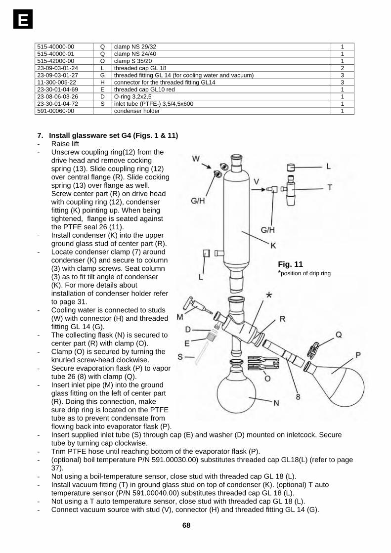
E 515-40000-00 Q clamp NS 29/32 1 515-40000-01 Q clamp NS 24/40 1 515-42000-00 O clamp S 35/20 1 23-09-03-01-24 L threaded cap GL 18 2 23-09-03-01-27 G threaded fitting GL 14 (for cooling water and vacuum) 3 11-300-005-22 H connector for the threaded fitting GL14 3 23-30-01-04-69 E threaded cap GL10 red 1 23-08-06-03-26 D O-ring 3,2x2,5 1 23-30-01-04-72 S inlet tube (PTFE-) 3,5/4,5x600 1 591-00060-00 condenser holder 1 7. Install glassware set G4 (Figs. 1 & 11) - Raise lift - Unscrew coupling ring(12) from the
drive head and remove cocking spring (13). Slide coupling ring (12) over central flange (R). Slide cocking spring (13) over flange as well. Screw center part (R) on drive head with coupling ring (12), condenser fitting (K) pointing up. When being tightened, flange is seated against the PTFE seal 26 (11).
- Install condenser (K) into the upper ground glass stud of center part (R).
- Locate condenser clamp (7) around condenser (K) and secure to column (3) with clamp screws. Seat column (3) as to fit tilt angle of condenser (K). For more details about installation of condenser holder refer to page 31.
- Cooling water is connected to studs (W) with connector (H) and threaded fitting GL 14 (G).
- The collecting flask (N) is secured to center part (R) with clamp (O).
- Clamp (O) is secured by turning the knurled screw-head clockwise.
- Secure evaporation flask (P) to vapor tube 26 (8) with clamp (Q).
- Insert inlet pipe (M) into the ground glass fitting on the left of center part (R). Doing this connection, make sure drip ring is located on the PTFE tube as to prevent condensate from flowing back into evaporator flask (P).
- Insert supplied inlet tube (S) through cap (E) and washer (D) mounted on inletcock. Secure tube by turning cap clockwise.
- Trim PTFE hose until reaching bottom of the evaporator flask (P). - (optional) boil temperature P/N 591.00030.00) substitutes threaded cap GL18(L) (refer to page
37). - Not using a boil-temperature sensor, close stud with threaded cap GL 18 (L). - Install vacuum fitting (T) in ground glass stud on top of condenser (K). (optional) T auto
temperature sensor (P/N 591.00040.00) substitutes threaded cap GL 18 (L). - Not using a T auto temperature sensor, close stud with threaded cap GL 18 (L). - Connect vacuum source with stud (V), connector (H) and threaded fitting GL 14 (G).
Fig. 11 *position of drip ring
69
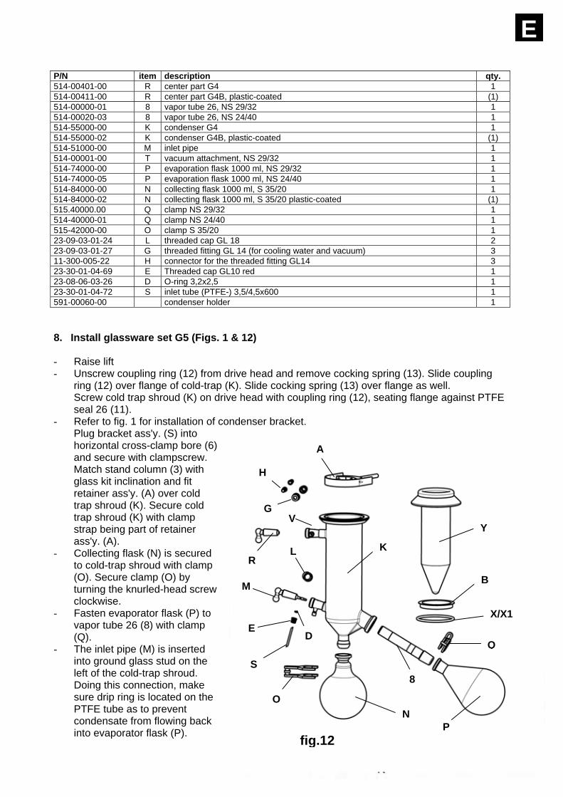
E P/N item description qty. 514-00401-00 R center part G4 1 514-00411-00 R center part G4B, plastic-coated (1) 514-00000-01 8 vapor tube 26, NS 29/32 1 514-00020-03 8 vapor tube 26, NS 24/40 1 514-55000-00 K condenser G4 1 514-55000-02 K condenser G4B, plastic-coated (1) 514-51000-00 M inlet pipe 1 514-00001-00 T vacuum attachment, NS 29/32 1 514-74000-00 P evaporation flask 1000 ml, NS 29/32 1 514-74000-05 P evaporation flask 1000 ml, NS 24/40 1 514-84000-00 N collecting flask 1000 ml, S 35/20 1 514-84000-02 N collecting flask 1000 ml, S 35/20 plastic-coated (1) 515.40000.00 Q clamp NS 29/32 1 514-40000-01 Q clamp NS 24/40 1 515-42000-00 O clamp S 35/20 1 23-09-03-01-24 L threaded cap GL 18 2 23-09-03-01-27 G threaded fitting GL 14 (for cooling water and vacuum) 3 11-300-005-22 H connector for the threaded fitting GL14 3 23-30-01-04-69 E Threaded cap GL10 red 1 23-08-06-03-26 D O-ring 3,2x2,5 1 23-30-01-04-72 S inlet tube (PTFE-) 3,5/4,5x600 1 591-00060-00 condenser holder 1 8. Install glassware set G5 (Figs. 1 & 12) - Raise lift - Unscrew coupling ring (12) from drive head and remove cocking spring (13). Slide coupling
ring (12) over flange of cold-trap (K). Slide cocking spring (13) over flange as well. Screw cold trap shroud (K) on drive head with coupling ring (12), seating flange against PTFE seal 26 (11).
- Refer to fig. 1 for installation of condenser bracket. Plug bracket ass'y. (S) into horizontal cross-clamp bore (6) and secure with clampscrew. Match stand column (3) with glass kit inclination and fit retainer ass'y. (A) over cold trap shroud (K). Secure cold trap shroud (K) with clamp strap being part of retainer ass'y. (A).
- Collecting flask (N) is secured to cold-trap shroud with clamp (O). Secure clamp (O) by turning the knurled-head screw clockwise.
- Fasten evaporator flask (P) to vapor tube 26 (8) with clamp (Q).
- The inlet pipe (M) is inserted into ground glass stud on the left of the cold-trap shroud. Doing this connection, make sure drip ring is located on the PTFE tube as to prevent condensate from flowing back into evaporator flask (P). Fig. 12
*position of drip ring
A
Q
fig.12
Y
B
X/X1
P N
8
K
A
H
G
RL
M
O
E
S
D
V
70
E - Trim PTFE hose until reaching bottom of evaporator flask (P). - Insert supplied inlet tube (S) through cap (E) and washer (D) mounted on inletcock. Secure
tube by turning cap clockwise. - The (optional) boil-temperature sensor (P/N 591.00030.00) can be used in place of the
threaded cap GL 18(L). - Not using a boil-temperature sensor, close stud with threaded cap GL 18 (L). - Locate gasket (X= silicon with FEP, or X1= silicon) in sealing groove of cold trap shroud (K).
Insert centering ring (B) in cold trap shroud (K) and insert cold trap (Y) in cold trapshroud (K). - Connect vacuum source with stud (V), connector (H) and threaded fitting GL 14 (G).
P/N item name qty. 514-00000-01 8 vapor tube 26, NS 29/32 1 514-00020-03 8 vapor tube 26, NS 24/40 1 514-00500-00 K cold-trap shroud 1 514-00510-01 K cold-trap shroud, plastic-coated (1) 514-00501-00 Y cold-trap 1 23-30-01-01-39 X seal G5 (Silicon/FEP) 1 23-30-01-01-88 X1 seal G5 1 514-51000-00 M inlet pipe 1 514-74000-00 P evaporator flask 1000 ml, NS 29/32 1 514-74000-05 P evaporator flask 1000 ml, NS 24/40 1 514-84000-00 N collecting flask 1000 ml, S 35/20 1 514-84000-02 N collecting flask 1000 ml, S 35/20 plastic-coated (1) 515-40000-00 Q clamp NS 29/32 1 515-40000-01 Q clamp NS 24/40 1 515-42000-00 O clamp S 35/20 1 23-09-03-01-24 L threaded cap GL 18 1 23-09-03-01-27 G threaded fitting GL 14 (for cooling water and vacuum) 2 11-300-005-22 H connector for threaded fitting GL14 2 591-00061-00 A retainer ass`y 1 23-30-01-04-88 B centering ring 1 23-30-01-04-69 E Threaded cap GL10 red 1 23-08-06-03-26 D O-ring 3,2x2,5 1 23-30-01-04-72 S inlet tube (PTFE-) 3,5/4,5x600 1 15-003-003-24 R cock-plug: NS 19/38 1

71
E9. Install glassware set G6 (Figs. 1 & 13) - Raise lift - Unscrew coupling ring (12) from drive head and remove cocking spring (13). Slide coupling
ring (12) over center part flange. Slide cocking spring (13) over flange as well. Screw cold trap shroud (K) on drive head with coupling ring (12), seating flange against PTFE seal 26 (11).
- Screw coupling ringG6 (U) on drive head and insert adapter G6 (Z) with seal G6 (D) in coupling ring G6 (U). The adapter (Z) is seated against the PTFE seal 26 (11)
- Screw center part (R) on coupling ring G6 (U) (12); flange is seated against seal G6 (D).
- Install condenser (K) into the upper ground-glass stud of center part (R). Locate condenser clamp (7) around condenser (K) and secure to column (3) with clamp screw. For installation of the condenser holder refer to fig. 1.
- Cooling water is connected to studs (W) with connector (H) and threaded fitting GL 14 (G).
- Collecting flask (N) is secured on the center part (R) with clamp (O). Clamp (O) is secured by turning knurled-head screw clockwise
- Fasten the evaporator flask (P) to vapor tube 26 (8) with clamp (Q). The inlet pipe (M) is inserted into the ground glass stud on the left of the center part (R). Doing this connection, make sure the drip ring is located on the PTFE tube as to prevent condensate from flowing back into the evaporator flask (P).
- Insert supplied inlet tube (S) through cap (E) and washer (D) mounted on inletcock. Secure tube by turning cap clockwise.
- The (optional) boil-temperature sensor (P/N 591.00030.00) substitutes threaded cap GL 18 (L).
- Not using a boil-temperature sensor, close stud with threaded cap GL 18 (L).
R
Z D 1312
11
U
fig. 14
Fig 13 *position of drip ring
72
E - Insert the vacuum attachment (T) into the ground-glass socket at the upper end of the
condenser (K). The temperature sensor T auto (accessory No. 591.00040.00) can be used in place of the threaded sealing cap GL 18 (L).
- Not using a T auto sensor, close stud with threaded cap GL 18 (L). - Connect vacuum source to stud (V). connector (H) and threaded fitting GL 14 (G).
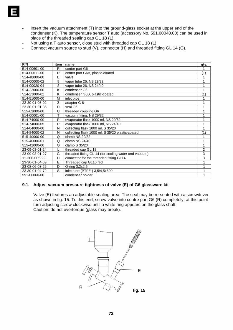
P/N item name qty. 514-00601-00 R center part G6 1 514-00611-00 R center part G6B, plastic-coated (1) 514-48000-00 E valve 1 514-00000-02 8 vapor tube 26, NS 29/32 1 514-00020-04 8 vapor tube 26, NS 24/40 1 514-23000-00 K condenser G6 1 514-23000-02 K condenser G6B, plastic-coated (1) 514-51000-00 M inlet pipe 1 22-30-01-05-02 Z adapter G 6 1 23-30-01-01-35 D seal G6 1 515-62000-00 U threaded coupling G6 1 514-00001-00 T vacuum fitting, NS 29/32 1 514-74000-00 P evaporator flask 1000 ml, NS 29/32 1 514-74000-05 P evaporator flask 1000 ml, NS 24/40 1 514-84000-00 N collecting flask 1000 ml, S 35/20 1 514-84000-02 N collecting flask 1000 ml, S 35/20 plastic-coated (1) 515-40000-00 Q clamp NS 29/32 1 515-40000-01 Q clamp NS 24/40 1 515-42000-00 O clamp S 35/20 1 23-09-03-01-24 L threaded cap GL 18 2 23-09-03-01-27 G threaded fitting GL 14 (for cooling water and vacuum) 3 11-300-005-22 H connector for the threaded fitting GL14 3 23-30-01-04-69 E Threaded cap GL10 red 1 23-08-06-03-26 D O-ring 3,2x2,5 1 23-30-01-04-72 S inlet tube (PTFE-) 3,5/4,5x600 1 591-00060-00 condenser holder 1 9.1. Adjust vacuum pressure tightness of valve (E) of G6 glassware kit
Valve (E) features an adjustable sealing area. The seal may be re-seated with a screwdriver as shown in fig. 15. To this end, screw valve into centre part G6 (R) completely; at this point turn adjusting screw clockwise until a white ring appears on the glass shaft. Caution: do not overtorque (glass may break).
E
fig. 15 R
73
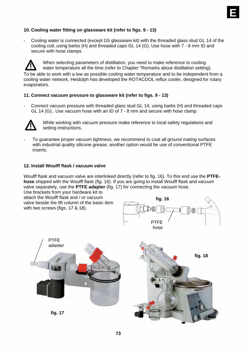
E10. Cooling water fitting on glassware kit (refer to figs. 9 - 13) - Cooling water is connected (except G5 glassware kit) with the threaded glass stud GL 14 of the
cooling coil, using barbs (H) and threaded caps GL 14 (G). Use hose with 7 - 8 mm ID and secure with hose clamps.
When selecting parameters of distillation, you need to make reference to cooling water temperature all the time (refer to Chapter "Remarks about distillation setting).
To be able to work with a low as possible cooling water temperature and to be independent from a cooling water network, Heidolph has developed the ROTACOOL reflux cooler, designed for rotary evaporators. 11. Connect vacuum pressure to glassware kit (refer to figs. 9 - 13) - Connect vacuum pressure with threaded glass stud GL 14, using barbs (H) and threaded caps
GL 14 (G).. Use vacuum hose with an ID of 7 - 8 mm and secure with hose clamp.
While working with vacuum pressure make reference to local safety regulations and setting instructions.
- To guarantee proper vacuum tightness, we recommend to coat all ground mating surfaces
with industrial quality silicone grease; another option would be use of conventional PTFE inserts.
12. Install Woulff flask / vacuum valve Woulff flask and vacuum valve are interlinked directly (refer to fig. 16). To this end use the PTFE-hose shipped with the Woulff flask (fig. 16). If you are going to install Woulff flask and vacuum valve separately, use the PTFE adapter (fig. 17) for connecting the vacuum hose. Use brackets from your hardware kit to attach the Woulff flask and / or vacuum valve beside the lift column of the basic item with two screws (figs. 17 & 18).
PTFEhose
fig. 16
fig. 17
fig. 18
PTFE adapter
74
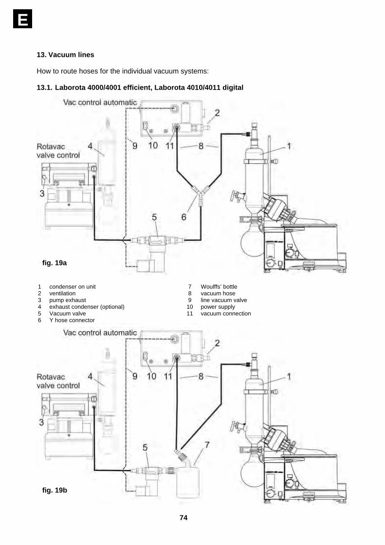
E 13. Vacuum lines How to route hoses for the individual vacuum systems: 13.1. Laborota 4000/4001 efficient, Laborota 4010/4011 digital
1 condenser on unit 7 Woulffs’ bottle 2 ventilation 8 vacuum hose 3 pump exhaust 9 line vacuum valve 4 exhaust condenser (optional) 10 power supply 5 Vacuum valve 11 vacuum connection 6 Y hose connector
fig. 19a
fig. 19b

75
E13.2. Laborota 4002/4003 control with Rotavac valve control
1 condenser on unit 7 Woulffs’ bottle 2 ventilation 8 vacuum hose 3 pump exhaust 9 line vacuum valve 4 exhaust condenser (optional) 10 power supply 5 Vacuum valve 11 vacuum connection 6 Y hose connector 12 data line
fig. 20a
fig. 20b
76
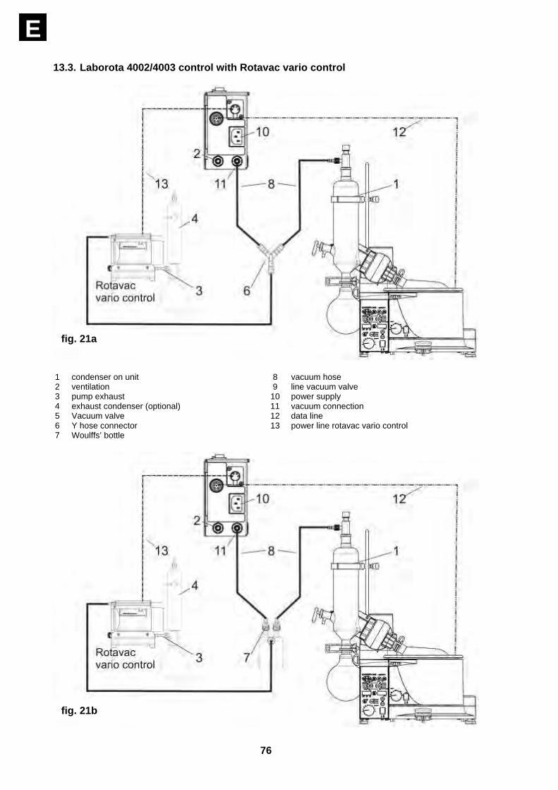
E 13.3. Laborota 4002/4003 control with Rotavac vario control
1 condenser on unit 8 vacuum hose 2 ventilation 9 line vacuum valve 3 pump exhaust 10 power supply 4 exhaust condenser (optional) 11 vacuum connection 5 Vacuum valve 12 data line 6 Y hose connector 13 power line rotavac vario control 7 Woulffs’ bottle
fig. 21a
fig. 21b

77
E14. Install protective hood, fig. 22 (option P/N 591.00010.00) - This protective hood (25) protects the user from glass fragments, a possible shock wave will
escape via the top end. This hood guarantees adequate protection in both, the operational mode and with the lift in upper position.
- The protective hood (25) with its structural member is attached to the vertical stop (15) with 2 screws. For opening or closing the protective hood (25) through 90 degrees, use the handle provided. To displace the protective hood (25) loosen clamp screw (16); this way, you can locate the hood over the center of the hot bath; if, for example (using bigger-size evaporator flasks), the hot bath may be displaced to the right and the protective hood (25) arranged in the right place. Secure with clamp screw (16).
15. Install protective shield, fig. 23 (option P/N 591.00020.00) - With the lift in its upper position, a protective shield (17) will protect the operator from
fragments, e.g. when replacing a flask still being under vacuum.
- The protective shield is hooked-up at the hot bath's metallic frame (2) and clamped with screw (18) (180° turn). Make sure plane of eccenter is pointing up.
25a 25
15
14 16
fig. 22

78
E Before clamping, position protective shield (17) in a manner that allows to open the protective hood (25) without collision (try out).
16. Install boil temperature sensor (option P/N 591.00030.00) for LABOROTA 4002/ 4003 control and LABOROTA 4010/4011 digital
- A boil temperature sensor is needed for the LABOROTA digital/control to monitor vapor
temperature during distillation.
- The boil temperature sensor is installed in place of a screwed cap (L) (depends on glassware kit used, refer to figs. 9 - 13).
- Unthread cap (L), install boil temperature sensor and secure with coupling ring (26).
Install seal with its white PTFE end pointing to the glass thread, instead of screwed cap (26).
- The boil temperature sensor is connected to a 4-pin bayonet-type socket in the item's rear
panel (refer to fig. 2). 17. Install T auto temperature sensor (option P/N 591.00040.00) - The T auto temperature sensor is needed for automatic distillation control, using G3, G4 & G6
glassware kits (also refer to Chapter 34.4.2 T auto settings and Chapter 38.2 vacuum regulating mode T auto). The temperature sensor substitutes screwed cap (L) (depending of glassware kit, refer to figs. 10, 11 & 13).
- Unthread cap (L), install temperature sensor and secure with coupling ring (26).
Install seal with its white PTFE end pointing to the glass thread, instead of screwed cap (26).
- The temperature sensor is connected to a 4-pin bayonet-type socket in the item's rear panel
(refer to fig. 2).
17
17
2
2 18
fig. 23
26
fig. 24

79
E - Vertical location of the T auto
temperature sensor: lower edge of sensor at 2/3 of condenser height (for operation and settings of the T auto software refer to Chapter 34.4.2).
T auto temperature sensor and boil temperature sensor cannot be used at the same time.
18. Install remote control (option P/N 591.00050.00) for LABOROTA 4001 efficient, 4011
digital and 4003 control)
- The LABOROTA 4001 efficient, 4011 digital and 4003 control rotary evaporators feature a remote control for the lift. On the LABOROTA 4003 control, an extra feature is remote vacuum control and rotation control.
- The remote control itself features 3 meters of wire and is connected with a 7-pin bayonet-type socket in the rear panel of the item refer to fig. 2).
26
fig. 25
fig. 26
80
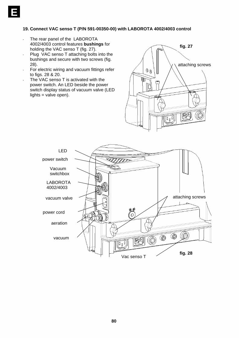
E 19. Connect VAC senso T (P/N 591-00350-00) with LABOROTA 4002/4003 control - The rear panel of the LABOROTA
4002/4003 control features bushings for holding the VAC senso T (fig. 27).
- Plug VAC senso T attaching bolts into the bushings and secure with two screws (fig. 28).
- For electric wiring and vacuum fittings refer to figs. 28 & 20.
- The VAC senso T is activated with the power switch. An LED beside the power switch display status of vacuum valve (LED lights = valve open).
attaching screws
fig. 27
LED
power switch
Vacuum switchbox
LABOROTA 4002/4003
vacuum valve
power cord
aeration
vacuum
attaching screws
fig. 28 Vac senso T
81
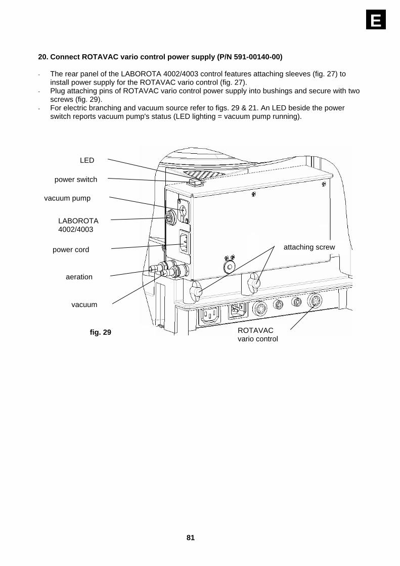
E 20. Connect ROTAVAC vario control power supply (P/N 591-00140-00) - The rear panel of the LABOROTA 4002/4003 control features attaching sleeves (fig. 27) to
install power supply for the ROTAVAC vario control (fig. 27). - Plug attaching pins of ROTAVAC vario control power supply into bushings and secure with two
screws (fig. 29). - For electric branching and vacuum source refer to figs. 29 & 21. An LED beside the power
switch reports vacuum pump's status (LED lighting = vacuum pump running).
LED
power switch
vacuum pump
LABOROTA 4002/4003
power cord
vacuum
aeration
attaching screw
ROTAVAC vario control
fig. 29
82
E
CONTROLS AND OPERATION
Before connecting power cord with outlet, make sure that: - item's voltage and frequency are the same as your local power
supply network (refer to data plate on item). - power switches are OFF ("0"). control knobs are at their lefthand
stop, in order to avoid accidential rotation of the evaporator flask.
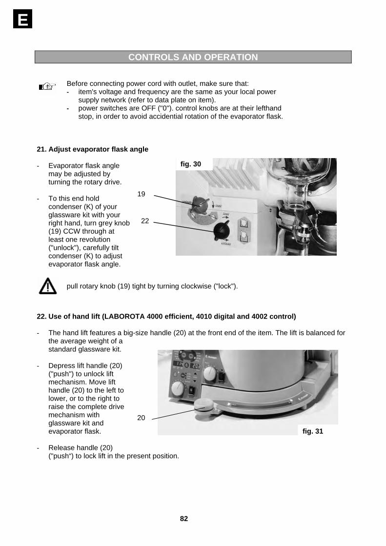
21. Adjust evaporator flask angle - Evaporator flask angle
may be adjusted by turning the rotary drive.
- To this end hold condenser (K) of your glassware kit with your right hand, turn grey knob (19) CCW through at least one revolution ("unlock"), carefully tilt condenser (K) to adjust evaporator flask angle.
pull rotary knob (19) tight by turning clockwise ("lock").
22. Use of hand lift (LABOROTA 4000 efficient, 4010 digital and 4002 control) - The hand lift features a big-size handle (20) at the front end of the item. The lift is balanced for
the average weight of a standard glassware kit.
- Depress lift handle (20) ("push") to unlock lift mechanism. Move lift handle (20) to the left to lower, or to the right to raise the complete drive mechanism with glassware kit and evaporator flask.
- Release handle (20) ("push“) to lock lift in the present position.
19
22
fig. 30
20
fig. 31

83
E 23. Use of power lift (LABOROTA 4001 efficient, 4011 digital and 4003 control) - Turn power switch (1b) ON and run
power lift with arrow keys. Lift is going to move as long as one of the arrow keys is held depressed.
- On the LABOROTA 4003 control, the arrow keys (up and down) also are used to enter parameters of distillation. For lift control you need to select the "set" mode. "Set" mode automatically is reset after 5 seconds.
24. Adjust immersion depth of evaporator flask (also refer to figs. 22 & 30) - The lift is used to immerse the evaporator flask in the bath fluid. To use the same immersion
depth for all distilling jobs, we recommend to firmly set immersion depth.
- To this end loosen black rotary knob (22, fig. 30) on lift column by turning CCW ("unlock"). Vertical stop (15) drops (sustain by pulling down). Descend lift until reaching proper immersion depth in heating bath (2). It may be required to sustain this action by hand, if lift won't move when hitting the arrow keys (tu). Pull rotary knob tight (22, fig. 30) by turning clockwise ("lock"). At this point, immersion depth of the evaporator flask is set permanently.
- If immersion depth is not satisfactory after adjustment, repeat above steps.
If protective hood is installed, you will need to displace vertical stop (15) by hand:
- Loosen vertical stop (15) with black
rotary knob (22, fig. 30) ("unlock"), hold protective hood's frame (14, fig. 22) and move vertical stop till hitting upper end. Pull rotary knob (22, fig. 30) tight ("lock“).
- Descend lift with arrow key uuntil
1b
arrow keys
fig. 32
15 2
fig. 33
14
15
fig. 34

84
E reaching immersed depth wanted.
- Hold protective hood's frame with your hand, the other hand is going to loosen the black rotary knob (22) ("unlock"), and slip vertical lock (15) down to its extreme position. Pull rotary knob (22) tight ("lock").
protective hood goes on the vertical stop (15), refer to fig. 22. The lift being lowered will guarantee permanent immersed depth in the hot bath, as specified before.
25. Evaporator flask draw-off fixture - An evaporator flask draw-off system allows to loosen a stuck evaporator flask (P) from the
vapor tube (8) at ease.
- Remove flask clamp (Q). Hold evaporator flask with your right hand (use gloves to avoid burns). With your left hand turn draw-off nut (24) CCW until evaporator flask is drawn off.
hold evaporator flask (P), do not drop into hot bath (flask might be broken, hazard of splashes).
evaporator flask (P) may be hot ! Allow to chill before handling, or use gloves.
allow hot bath to chill, in order to avoid burns.
26. Displace heating bath (figs. 35 & 36) - Using bigger-size evaporator
flasks or couplings between evaporator flasks and vapor tube (8, fig. 35), you will need to increase clearance between hot bath and drive head.
- All of the LABOROTA –models feature feet in rails, the heating bath can be displaced as required.
8
Q24
P
9
fig. 35
fig. 36
rails

85
E
After displacing, re-adjust immersed depth and angle of the evaporator flask (refer to Chapter 21).
- For extra extension beyond the range of displacement, an optional extension panel (P/N 591-
00090-00) is available; it attaches on the item with ease to give an added extension range of displacement to 160 mm.
27. Fill hot bath (fig. 37)
Using deionized or distilled water for filling the hot bath, you need to add 0.2 % of borax (Na2B4O7
*10H2O) as corrosion inhibitor. Please note:The use of tabwater as heating media can lead to calcification which can provoke crevice corrosion. Therefore the user is strongly recommended to clean the heating bath with an adequate polish on a regular basis.
- It is recommended to use the bath liquid, accessorie-part.no. 515-31000-00
Never run your heating bath (2) dry !
- Before heating, fill heating bath (2) with fluid. The bowl features min- and max. marks (2c).
Max. fill level may be reached with the evaporator flask immersed only. Using big-size evaporator flasks carefully immerse item in order to avoid spillage.
- For ease of transport, the hot bath (2) features rubber grips (2d) to improve friction.
Hazard of burns when running hot bath (2) at temperatures of more than 60° C. Beware of metal edge of hot bath, fluid and evaporator flask.
max min
2c 2d
2d
2b
2 2e
2a
fig. 37

86
E 28. Work with protective hood and protective shield (optional, P/N 591.00010.00 and
591.00020.00) (also refer to figs. 22 & 23) - If you cannot locate the rotary evaporator behind a glass shield, optional protective hood (25)
and shield (17) offer adequate protection for the user.
- The protective hood raises together with the lift, hence giving room for replacing the evaporator flask (P).
- Folding the protective hood up though 90° with its handle (25a) the evaporator flask's section (P) is accessible. As described in Chapter 14, the protective hood easily adjusts to fit position of the hot bath, e.g. if the hot bath needs to be displaced.
Do not open protective hood in lower position of lift, if you use hood and shield together (collision between hood and shield).
29. Add substance to be distilled (also refer to figs. 9 -13) - Substance to be distilled may be added through feeder tube (M), even under vacuum.
- Plug hose (6 - 7 mm dia.) over nipple (A, figs. 9 - 13) and immerse other end of hose in
container with the substance to be distilled.
- Open feed with plug of cock (M) (turn aperture of cock towards nipple). When closing cock (M) make sure not to turn the plug through more than 90 degrees.
30. Aerate by hand (also refer to figs. 9-13)
The cock in feeder tube (M) also allows system aeration by hand. To this end turn aperture in cock's plug up towards aerating hole (opposite hose liner).
31. Adjust hot bath temperature 31.1. LABOROTA 4000 / 4001 efficient and LABOROTA 4010 / 4011 digital - Turn hot bath ON with push-button (2a); button lighted green.
Turn power switch (1b, fig. 1) to ON before starting adjusting work.
87
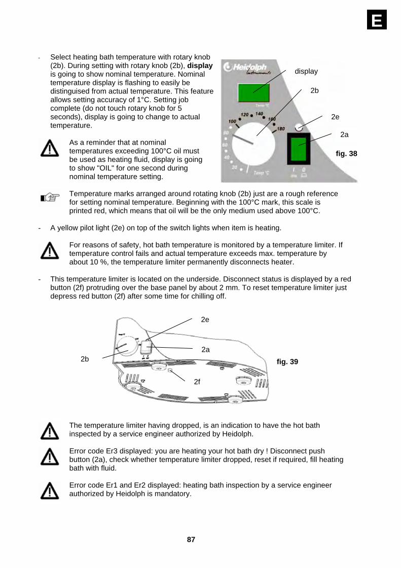
E - Select heating bath temperature with rotary knob
(2b). During setting with rotary knob (2b), display is going to show nominal temperature. Nominal temperature display is flashing to easily be distinguised from actual temperature. This feature allows setting accuracy of 1°C. Setting job complete (do not touch rotary knob for 5 seconds), display is going to change to actual temperature.
As a reminder that at nominal temperatures exceeding 100°C oil must be used as heating fluid, display is going to show "OIL" for one second during nominal temperature setting.
Temperature marks arranged around rotating knob (2b) just are a rough reference for setting nominal temperature. Beginning with the 100°C mark, this scale is printed red, which means that oil will be the only medium used above 100°C.
- A yellow pilot light (2e) on top of the switch lights when item is heating.
For reasons of safety, hot bath temperature is monitored by a temperature limiter. If temperature control fails and actual temperature exceeds max. temperature by about 10 %, the temperature limiter permanently disconnects heater.
- This temperature limiter is located on the underside. Disconnect status is displayed by a red
button (2f) protruding over the base panel by about 2 mm. To reset temperature limiter just depress red button (2f) after some time for chilling off.
The temperature limiter having dropped, is an indication to have the hot bath inspected by a service engineer authorized by Heidolph.
Error code Er3 displayed: you are heating your hot bath dry ! Disconnect push button (2a), check whether temperature limiter dropped, reset if required, fill heating bath with fluid.
Error code Er1 and Er2 displayed: heating bath inspection by a service engineer authorized by Heidolph is mandatory.
display
2b
2e
2a
fig. 38
2b
2e
2a
2f
fig. 39

88
E 31.2. LABOROTA 4002 / 4003 control LABOROTA 4002 and 4003 control: adjust nominal temperature on basic item's control panel as described below.
Select “Set Bath“ with select key and set nominal temperature with arrow keys. Nominal temperature is displayed. After 5 seconds, display automatically returns to actual indication (Act Bath).
As a reminder: at nominal temperatures exceeding 100 °C oil needs to be used for heat carrier, the term "OIL" is displayed for about 1 second, if nominal of more than 100°C is selected.
The LABOROTA 4002 / 4003 control temperature control (2b) works as temperature limiter; it should be set to at least 20°C above nominal.
32. Turn on and set rotary speed (also refer to fig. 1)
First turn rotary evaporator's power switch (1b) to ON.
Before turning power switch to ON, make sure temperature control knob (1c) is in extreme left position to avoid accidential rotation of the evaporator flask.
select
set Bath
display
arrow keys
fig. 41
fig. 40
variable temperature limiter
89
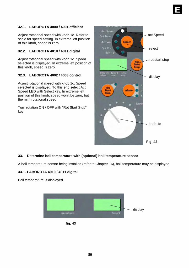
E 32.1. LABOROTA 4000 / 4001 efficient Adjust rotational speed with knob 1c. Refer to scale for speed setting. In extreme left position of this knob, speed is zero. 32.2. LABOROTA 4010 / 4011 digital Adjust rotational speed with knob 1c. Speed selected is displayed. In extreme left position of this knob, speed is zero. 32.3. LABOROTA 4002 / 4003 control Adjust rotational speed with knob 1c. Speed selected is displayed. To this end select Act Speed LED with Select key. In extreme left position of this knob, speed won't be zero, but the min. rotational speed. Turn rotation ON / OFF with "Rot Start Stop" key. 33. Determine boil temperature with (optional) boil temperature sensor A boil temperature sensor being installed (refer to Chapter 16), boil temperature may be displayed. 33.1. LABOROTA 4010 / 4011 digital Boil temperature is displayed.
act Speed
select
display
rot start stop
knob 1c
Fig. 42
display
fig. 43
90
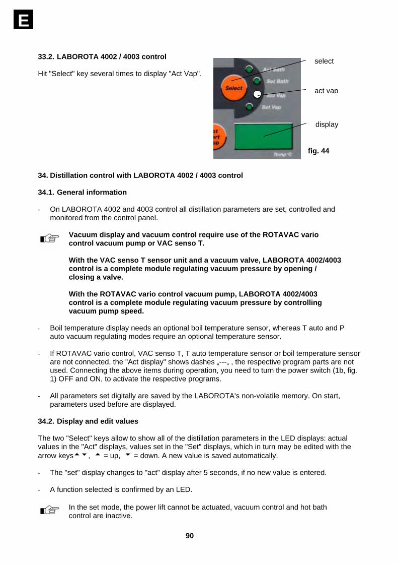
E 33.2. LABOROTA 4002 / 4003 control Hit "Select" key several times to display "Act Vap". 34. Distillation control with LABOROTA 4002 / 4003 control 34.1. General information - On LABOROTA 4002 and 4003 control all distillation parameters are set, controlled and
monitored from the control panel.
Vacuum display and vacuum control require use of the ROTAVAC vario control vacuum pump or VAC senso T. With the VAC senso T sensor unit and a vacuum valve, LABOROTA 4002/4003 control is a complete module regulating vacuum pressure by opening / closing a valve. With the ROTAVAC vario control vacuum pump, LABOROTA 4002/4003 control is a complete module regulating vacuum pressure by controlling vacuum pump speed.
- Boil temperature display needs an optional boil temperature sensor, whereas T auto and P
auto vacuum regulating modes require an optional temperature sensor.
- If ROTAVAC vario control, VAC senso T, T auto temperature sensor or boil temperature sensor are not connected, the "Act display" shows dashes „---„ , the respective program parts are not used. Connecting the above items during operation, you need to turn the power switch (1b, fig. 1) OFF and ON, to activate the respective programs.
- All parameters set digitally are saved by the LABOROTA's non-volatile memory. On start, parameters used before are displayed.
34.2. Display and edit values The two "Select" keys allow to show all of the distillation parameters in the LED displays: actual values in the "Act" displays, values set in the "Set" displays, which in turn may be edited with the arrow keystu, t = up, u = down. A new value is saved automatically. - The "set" display changes to "act" display after 5 seconds, if no new value is entered.
- A function selected is confirmed by an LED.
In the set mode, the power lift cannot be actuated, vacuum control and hot bath control are inactive.
select
act vap
fig. 44
display

91
E The lefthand Select-key selects the following parameters: Act Speed = actual rotational speed (rpm) Set Time = distillation time in minutes Act Vac = actual vacuum in mbar (with ROTAVAC vario control or VAC senso T
only) Set Vac = nominal vacuum in mbar (with ROTAVAC vario control or VAC senso T
only) Set Δ p = vacuum switching offset (hysteresis) in mbar (VAC senso T only) The righthand Select-key selects the following parameters: Act Bath = actual hot bath temperature in °C Set Bath = nominal hot bath temperature in °C Act Vap = actual boil / control temperature in °C (with boil temperature sensor or
or T auto temperature sensor only) Set Vap = nominal control temperature in °C (with T auto temperature sensor only) 34.3. Activate / deactivate vacuum control The Vac Start Stop key turns vacuum control ON and OFF. An LED beside this key is going to confirm operation of vacuum control.
Vacuum regulation being OFF, the aerating valve remains open. Hitting the Vac Start Stop key, foaming reactions during distillation may be stopped. The system is aerated thus decreasing vacuum pressure level. Hitting the Vac Start Stop key once more returns system to normal vacuum control mode.
34.4. Select vacuum control mode 3 different kinds of vacuum control can be selected with the "Mode" key. 34.4.1. p const, settings - In the p const mode, vacuum pressure is maintained as selected before.
- Hit Select key several times to get access to the
"set Vac" mode; select nominal vacuum with arrow keys tu. This value is displayed. The same way, Set Δp is used to select Δp. Δp is the hysteresis of vacuum control valve.
To extend service life of vacuum valve and electronics, we recommend to set Δp to a level avoiding frequent triggering of the valve (also refer to Chapter 38).
LED
key vac start stop
fig. 45
P const
P auto T auto
fig 46
select
set vac
set Δp
display
fig 47
92
E
Using the ROTAVAC vario control (speed controlled) does not need Δp setting, since vacuum control is derived from vacuum pump speed only. Selecting Set Δp, dashes only appear in display.
34.4.2. T auto, settings
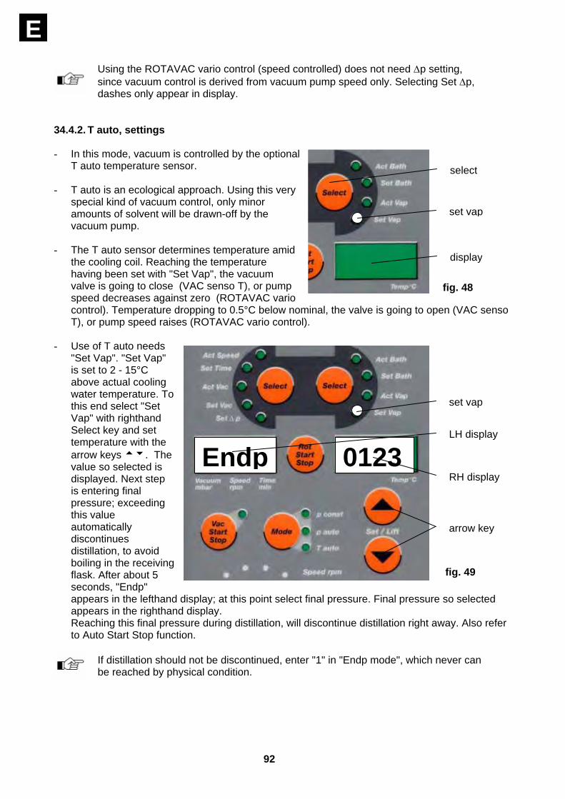
- In this mode, vacuum is controlled by the optional
T auto temperature sensor.
- T auto is an ecological approach. Using this very special kind of vacuum control, only minor amounts of solvent will be drawn-off by the vacuum pump.
- The T auto sensor determines temperature amid the cooling coil. Reaching the temperature having been set with "Set Vap", the vacuum valve is going to close (VAC senso T), or pump speed decreases against zero (ROTAVAC vario control). Temperature dropping to 0.5°C below nominal, the valve is going to open (VAC senso T), or pump speed raises (ROTAVAC vario control).
- Use of T auto needs "Set Vap". "Set Vap" is set to 2 - 15°C above actual cooling water temperature. To this end select "Set Vap" with righthand Select key and set temperature with the arrow keys tu. The value so selected is displayed. Next step is entering final pressure; exceeding this value automatically discontinues distillation, to avoid boiling in the receiving flask. After about 5 seconds, "Endp" appears in the lefthand display; at this point select final pressure. Final pressure so selected appears in the righthand display. Reaching this final pressure during distillation, will discontinue distillation right away. Also refer to Auto Start Stop function.
If distillation should not be discontinued, enter "1" in "Endp mode", which never can be reached by physical condition.
select
set vap
display
fig. 48
Endp 0123
arrow key
RH display
LH display
set vap
fig. 49

93
E 34.4.3. p auto, settings - The p auto vacuum control mode is a combination of T auto and p const. Determine distillation
point of the solvent; the pressure so determined is used for nominal pressure p const.
- The following parameters are going to be selected: - "Set Vap" (refer to Chapter 34.4.2) - "Endp" (refer to Chapter 34.4.2) - "Set Δp" (refer to Chapter 34.4.1) (not with ROTAVAC vario control vacuum pump).
- After having started distillation in p auto vacuum
regulating mode, p auto LED is going to light permanently. When reaching distillation point, the p const LED is going to flash.
34.5. Timer function - This function features 2 different timer modes: 34.5.1. TIME COUNTING: - This function measures the duration of the distillation. This is the time from switching on
rotation with the “Auto Start Stop” key or “Rot Start Stop” to switching rotation off. Select time counting mode - Select "Set Time" with lefthand Select key, and
set time displayed to "0" with the arrow keys tu.
- From starting rotation with the "Rot Start Stop" key, or "Auto Start Stop" key, time counting will be active until terminating rotation or hitting the "Auto Start Stop" key once more.
- Time may be displayed for 30 seconds after stop by selecting "Set Time" mode.
34.5.2. TIMER: - This function stops distillation after the preset period.
In this mode, duration of distillation can be selected. This time having elapsed, - vacuum control is discontinued, i.e. system is aerated - lift travels up (LABOROTA 4003 control only), and rotation is stopped.
TIMER setting - Got to "Set Time" with lefthand "Select" key, set time with arrow keys tu.
- Starting rotation with the "Rot Start Stop" or "Auto Start Stop" key, timer starts count-down and
discontinues distillation as described in para. 34.5.2 "timer". 30 seconds after the end of distillation, previous time setting is saved in the memory so that you do not need to set the same time once more, but just recall time and repeat the same action.
- During operation, the timer time can be subsequently corrected: Select “Set Time” with the left select key. Set the timer time by pressing the arrow keys tu.
P const
P auto
fig. 50
set time
select
display
fig. 51

94
E
If the timer has been set - even if having been saved accidentially - the processor is going to stop distillation. To avoid errors, the item is going to warn with 5 beeps and flashing display that a time is set and rotation is started with the "Rot Start Stop" key or "Auto Start Stop" key.
- To clear the pre-set time, hit "Rot Start Stop" or "Auto Start Stop" key once more and set time
to "zero". After setting, restart distillation with the "Rot Start Stop" or "Auto Start Stop" key.
During operation, you can change between the modes “Time Counting” and “Timer” or reset the timer time. Select “Set Time” with the left select key. Set the timer time by pressing the arrow keys tu or deactivate the timer (set display to “0”).
34.5.3. Time display - When selecting "Set Time", time will be displayed in the lefthand LED-display for 5 seconds, or,
in the "time counting mode", distillation time elapsed. After 5 seconds, display will return to rotary speed.
34.6. Discontinue evacuation Hitting the "Hold" key discontinues evacuation in all modes, the vacuum valve is going to close, or, if ROTAVAC vario control is used, vacuum pump is stopped. At this point, actual pressure is maintained as far as possible (physical paramters). This function is of particular importance in the p const mode, to avoid foaming. 34.7. Save actual p const as nominal value With the "Accept" key, present value can be saved as nominal p const during evacuation. 34.8. Save and recall distillation parameters Up to 9 different files (distillation parameter sets) may be saved. Every file contains: - Set Time - Set Vac - Set Δp - Set Bath - Set Vap - Endp - Mode - pressure ramp, as required
34.8.1. Save file - A file may be saved, als long as vacuum regulation is
inactive. Present values only are saved. Hitting the "Store" key, the next free memory appears on the lefthand display. e.g. "2". To overwrite a memory
hold
fig. 52
accept
fig. 53
store
fig. 54

95
Ealready existing, select this memory with the arrow keys. Memories occupied are marked by the memory number flashing. All 9 memories being used, "----" appears in the lefthand display; select memory you intend to overwrite with the arrow keys. Hitting the "Store" key once more will save the file; the same time a beep confirms this action.
34.8.2. Recall file - A file may be recalled as long as vacuum regulation is
inactive. - Hitting the "Recall" key, the lowest file number is recalled.
This file number appears in the lefthand display. Now you can go ahead selecting the file number wanted. Hitting the "Recall" key once more, will transfer your data into RAM. This action is confirmed by a beep.
34.9. Auto Start Stop function The "Auto Start Stop" combines various commands; it is also used for automatic start and stop of a distillation cycle (all function available with the LABOROTA 4003 control only power lift). Hitting the "Auto Start Stop" key starts the following actions: - lowers power lift - rotation ON - vaccum control ON - start timer
An LED beside the key confirms action selected. Caution: having one or more functions already started, the remaining function will started at this point only. Hit "Auto Start Stop" key once more is going to discontinue functions running: - Raise power lift - Rotation OFF - Vacuum control OFF - Stop time count
An LED beside the "Auto Start Stop" key is going to disappear. Automatic mode being active, all distillation parameters may be edited. 34.10. Pressure ramp: program, activate, save, and recall from memory. 34.10.1. Program and activate pressure ramp A pressure ramp may be used in the "p const" vacuum regulating mode only. All the time, this ramp starts at zero time and a pressure of 950 mb (close to atmosperic pressure). Hit the "Ramp set" key to start programming a pressure ramp, righthand display shows "t-1", actual pressure appearing in the lefthand display; use arrow keys for editing. To save this value, hit "Set Ramp" key once more. Righthand display shows "p-1" for the first pressure level. Edit figures appearing in lefthand display with arrow keys.
recall
fig. 55
auto start stop
LED fig. 56
auto start stop
fig. 57
ramp set
LED
ramp active
fig. 58
96
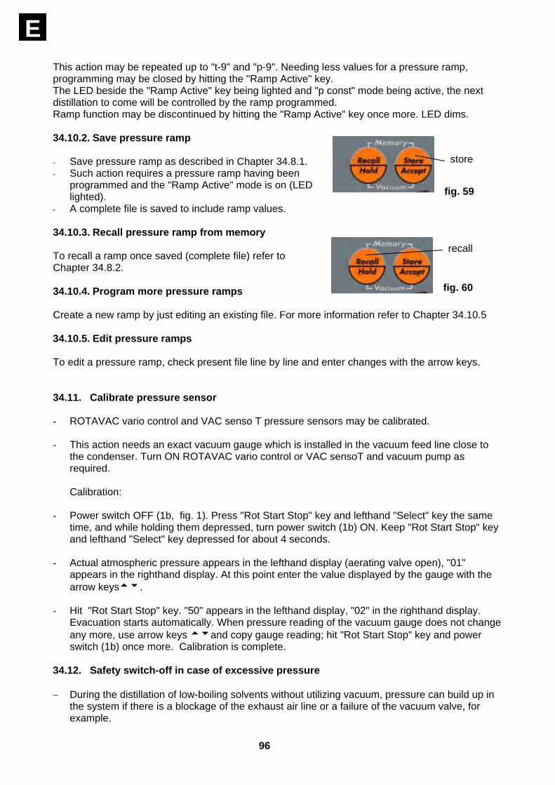
E This action may be repeated up to "t-9" and "p-9". Needing less values for a pressure ramp, programming may be closed by hitting the "Ramp Active" key. The LED beside the "Ramp Active" key being lighted and "p const" mode being active, the next distillation to come will be controlled by the ramp programmed. Ramp function may be discontinued by hitting the "Ramp Active" key once more. LED dims. 34.10.2. Save pressure ramp - Save pressure ramp as described in Chapter 34.8.1. - Such action requires a pressure ramp having been
programmed and the "Ramp Active" mode is on (LED lighted).
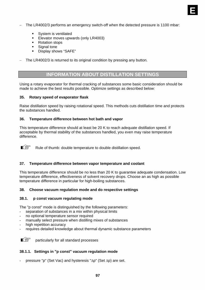
- A complete file is saved to include ramp values. 34.10.3. Recall pressure ramp from memory To recall a ramp once saved (complete file) refer to Chapter 34.8.2. 34.10.4. Program more pressure ramps Create a new ramp by just editing an existing file. For more information refer to Chapter 34.10.5 34.10.5. Edit pressure ramps To edit a pressure ramp, check present file line by line and enter changes with the arrow keys. 34.11. Calibrate pressure sensor - ROTAVAC vario control and VAC senso T pressure sensors may be calibrated.
- This action needs an exact vacuum gauge which is installed in the vacuum feed line close to
the condenser. Turn ON ROTAVAC vario control or VAC sensoT and vacuum pump as required. Calibration:
- Power switch OFF (1b, fig. 1). Press "Rot Start Stop" key and lefthand "Select" key the same time, and while holding them depressed, turn power switch (1b) ON. Keep "Rot Start Stop" key and lefthand "Select" key depressed for about 4 seconds.
- Actual atmospheric pressure appears in the lefthand display (aerating valve open), "01" appears in the righthand display. At this point enter the value displayed by the gauge with the arrow keystu.
- Hit "Rot Start Stop" key. "50" appears in the lefthand display, "02" in the righthand display. Evacuation starts automatically. When pressure reading of the vacuum gauge does not change any more, use arrow keys tuand copy gauge reading; hit "Rot Start Stop" key and power switch (1b) once more. Calibration is complete.
34.12. Safety switch-off in case of excessive pressure − During the distillation of low-boiling solvents without utilizing vacuum, pressure can build up in
the system if there is a blockage of the exhaust air line or a failure of the vacuum valve, for example.
store
fig. 59
recall
fig. 60
97
E− The LR4002/3 performs an emergency switch-off when the detected pressure is 1100 mbar:
System is ventilated Elevator moves upwards (only LR4003) Rotation stops Signal tone Display shows “SAFE”
− The LR4002/3 is returned to its original condition by pressing any button.
INFORMATION ABOUT DISTILLATION SETTINGS
Using a rotary evaporator for thermal cracking of substances some basic consideration should be made to achieve the best results possible. Optimize settings as described below: 35. Rotary speed of evaporator flask Raise distillation speed by raising rotational speed. This methods cuts distillation time and protects the substances handled. 36. Temperature difference between hot bath and vapor This temperature difference should at least be 20 K to reach adequate distillation speed. If acceptable by thermal stability of the substances handled, you even may raise temperature difference.
Rule of thumb: double temperature to double distillation speed.
37. Temperature difference between vapor temperature and coolant This temperature difference should be no less than 20 K to guarantee adequate condensation. Low temperature difference, effectiveness of solvent recovery drops. Choose an as high as possible temperature difference in particular for high-boiling substances. 38. Choose vacuum regulation mode and do respective settings 38.1. p const vacuum regulating mode The "p const" mode is distinguished by the following parameters: - separation of substances in a mix within physical limits - no optional temperature sensor required - manually select pressure when distilling mixes of substances - high repetition accuracy - requires detailed knowledge about thermal dynamic substance parameters
particularly for all standard processes
38.1.1. Settings in "p const" vacuum regulation mode - pressure "p" (Set Vac) and hysteresis "Δp" (Set Δp) are set.
98
E - choose pressure "p" as to locate boiling point of the substance to be distilled in the limits
defined by Chapters 36 and 37 (bath temperature and coolant temperature. To this end make note to reference chart and nomogram.
- Hysteresis Δp in "P const" mode defines temperature raise required to open the vacuum valve.
High valve opening times go in hand with high losses due to an increase in gas transfer.
- Low-boiling substances prefer a higher Δp value(5 - 10 mbar), whereas we recommend a low
value (1 - 5 mbar) for high-boiling substances. 38.2. "T auto" vacuum regulation mode The "T auto" mode is distinguished by the following parameters: - Find distillation point automatically and monitor for mixes - Requires optional "T auto" temperature sensor - Distillation of mixes won't require manual pressure control - Very high repetition accuracy - Easy to set - No need to know about thermal dynamic substance data
in particular for compliance with stringent environmental requirements / no-loss distillation and for distilling-off (mixes of substances)
38.2.1. Settings in "T auto" vacuum regulating mode - Setting does not require solvent data.
- Choose location of "T auto" temperature sensor as to split condenser 2/3 by 1/3, i.e. 2/3 is
available as condensation area, 1/3 being a safety reserve.
- Set nominal temperature "T" (Set Vap): As a function of its location, the "T auto" temperature sensor is going to detect temperature in the cooling circuit. "Set Vap" values just (2 – 15°C) above coolant temperature will guarantee distillation at high repetition accuracy. Extending temperature difference will increase distillation speed and decrease repetition accuracy.
38.3. "p auto" pressure regulating mode The "p auto" mode is a combination of of "T auto" and "p const", distinguished by the following parameters: - Find point of distillation automatically - Needs optional "T auto" temperature sensor - Cracking substances within physical limits - No need to know about termal dynamic substance data 38.3.1. Settings in "p auto" vacuum regulation mode - Set nominal temperature "T" (Set Vap) and the hysteresis Δp (Set Δp), when using - VAC senso T.
- Choose location of "T auto" temperature sensor as to split condenser 2/3 by 1/3, i.e. 2/3 is
available as condensation area, 1/3 being a safety reserve.
99
E- For more information about setting nominal temperature "T" T (Set Vap), refer to Chapter
34.4.2
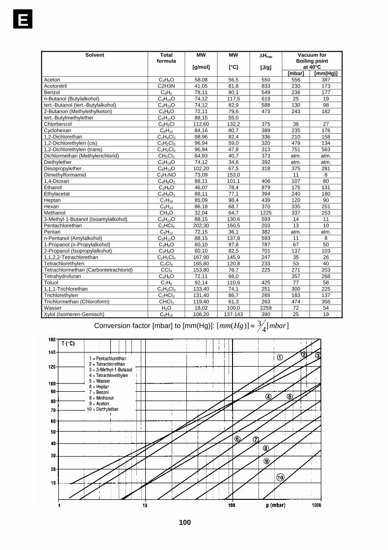
39. Solvent data Examples for using reference table and nomogram: This reference table details substance data needed for distillation, whereas the nomogram reflects relationship between pressure and boil temperature of some solvents. Go by the Clausius-Clapeyron equation and plot 1/T against log p. 39.1. at boil temperature of 40°C LABOROTA 4002/4003 control: in column "vacuum for boil temperature" use the "Set Vac" nominal value as depicted for 40°C. 39.2. at boil temperatures deviating from 40°C 1. On temperature axis of the nomogram mark boil temperature needed. 2. Draw a line to the right and determine intersection with the solvent line. 3. From this intersetion draw a straight line down to determine the vacuum pressure neeed for
this particular application. 39.3. solvents not depicted - The following items might help in determining the right vacuum pressure: 1. Rise of the straight line is a function of evaporation enthalpy. It is similar for similar chemical
substances with similar boil temperature. Hence, straight lines depicted may be used for rough reference to a lightly deviating boil point.
2. A water jet pump or diaphragm-type pump may lower boil temperature by about 100°C.
3. Rule of thumb: decrease pressure to ½ will decrease boil point by about 15°C.
100
E
Vacuum for Boiling point
at 40°C
Solvent Total formula
MW
[g/mol]
MW
[°C]
ΔHvap
[J/g] [mbar] [mm(Hg)]
Aceton C3H6O 58,08 56,5 550 556 387 Acetonitril C2H3N 41,05 81,8 833 230 173 Benzol C6H6 78,11 80,1 549 236 177 n-Butanol (Butylalkohol) C4H10O 74,12 117,5 619 25 19 tert.-Butanol (tert.-Butylalkohol) C4H10O 74,12 82,9 588 130 98 2-Butanon (Methylethylketon) C4H8O 72,11 79,6 473 243 182 tert.-Butylmethylether C5H12O 88,15 55,0 Chlorbenzol C6H5CI 112,60 132,2 375 36 27 Cyclohexan C6H12 84,16 80,7 389 235 176 1,2-Dichlorethan C2H4CI2 98,96 82,4 336 210 158 1,2-Dichlorethylen (cis) C2H2CI2 96,94 59,0 320 479 134 1,2-Dichlorethylen (trans) C2H2CI2 96,94 47,8 313 751 563 Dichlormethan (Methylenchlorid) CH2CI2 84,93 40,7 373 atm. atm. Diethylether C4H10O 74,12 34,6 392 atm. atm. Diisopropylether C6H14O 102,20 67,5 318 375 281 Dimethylformamid C3H7NO 73,09 153,0 11 8 1,4-Dioxan C4H8O2 88,11 101,1 406 107 80 Ethanol C2H6O 46,07 78,4 879 175 131 Ethylacetat C4H8O2 88,11 77,1 394 240 180 Heptan C7H16 85,09 98,4 439 120 90 Hexan C6H14 86,18 68,7 370 335 251 Methanol CH4O 32,04 64,7 1225 337 253 3-Methyl-1-Butanol (Isoamylalkohol) C5H12O 88,15 130,6 593 14 11 Pentachlorethan C2HCI5 202,30 160,5 203 13 10 Pentan C5H12 72,15 36,1 382 atm. atm. n-Pentanol (Amylalkohol) C5H12O 88,15 137,8 593 11 8 1-Propanol (n-Propylalkohol) C3H8O 60,10 97,8 787 67 50 2-Propanol (Isopropylalkohol) C3H8O 60,10 82,5 701 137 103 1,1,2,2-Tetrachlorethan C2H2CI4 167,90 145,9 247 35 26 Tetrachlorethylen C2CI4 165,80 120,8 233 53 40 Tetrachlormethan (Carbontetrachlorid) CCI4 153,80 76,7 225 271 203 Tetrahydrofuran C4H8O 72,11 66,0 357 268 Toluol C7H8 92,14 110,6 425 77 58 1,1,1-Trichlorethan C2H3CI3 133,40 74,1 251 300 225 Trichlorethylen C2HCI3 131,40 86,7 265 183 137 Trichlormethan (Chloroform) CHCI3 119,40 61,3 263 474 356 Wasser H2O 18,02 100,0 2259 72 54 Xylol (Isomeren-Gemisch) C8H10 106,20 137-143 390 25 19
Conversion factor [mbar] to [mm(Hg)]: ][43)]([ mbarHgmm ≈
101
ECLEANING AND MAINTENANCE
For cleaning, wipe housing with a damp cloth (add some sort of mild liquid soap).
NOTE: To avoid damage to the surface finish, avoid using chlorine bleach, chlorine-based cleaners, abrasive substances, ammonia, rags or cleaning pads containing metallic particles.
Vapor tube (8, fig. 6) and PTFE seal (11, fig. 6) need regular upkeep. To this end, remove, clean, and inspect vapor tube (8, fig. 6) and PTFE seal (11, fig. 6) (sealing edge); replace PTFE seal on condition. To re-install vapor tube and PTFE seal, make reference to Chapter 4.
The item is maintenance-free. Repair work is limited to engineers authorized to do so by HEIDOLPH. So therefore get in touch with your local HEIDOLPH dealer or field respresentative.
DISASSEMBLE, FORWARD & STORE
Disassemble Turn the item OFF and disconnect mains plug. Transport and store 3. Use orginal box or a similar pack to store your item in order to prevent damage in transit. Tape
box as required. 4. Store item in a dry place.
CAUTION: avoid shocks and vibration while in transit.
DISPOSAL
For disposal, please comply with your local or national regulations. Split by metal, plastic, etc. Packing material to be treated as described above (material split).

102
E
TROUBLESHOOTING
No heat: a) check power cord b) power switch (1b) broken (call service engineer) c) max. temperature limiter dropped (refer to Chapter 31.1) d) hot bath heater broken (call service engineer) e) LABOROTA 4002/4003 control: hot bath junction cable not connected f) "Set Bath" temperature higher than hot bath temperature control (hot bath temperature control
needs to be set to about 20°C over "Set bath" temperature (refer to Chapter 31.2) g) LABOROTA master switch (1b) OFF; (turn master switch 1b ON) Drive won't run: a) check power cord b) master switch (1b) broken (call service engineer) c) speed control knob at lefthand end, turn right d) motor problem (call service engineer) Power lift not working: a) check power cord b) master switch (1b) broken (call service engineer) c) lift located at final stop, hit opposite arrow key d) limit switch actuator pin stuck in base frame: repair e) mechanism / motor problem (call service engineer) f) vertical stop (15) not adjusted as specified (refer to Chapter 24) Insufficient vacuum: a) check seals and fittings b) check ground fittings, lubricate on condition c) check PTFE seal for proper installation (sealing edge faces drive head). Refer to "set-up, vapor
tube and seal", d) check vacuum pump's suction line Device unexpectedly switches off (LR4002/3): a) A timer time may be programmed, after which an automatic stop is performed. Check
whether the timer is set (compare with Chapter 34.5.2) and switch this off. Device unexpectedly switches off, display shows “SAFE” (LR4002/3): a) The safety switch-off system in case of excess pressure has activated.
The value measured by the sensor has exceeded 1100 mbar (compare with Chapter 34.12 Safety switch-off in case of excessive pressure)
b) The vacuum sensor may be out of calibration. Calibrate the vacuum sensor (compare with Chapter 34.11)

103
E
SPECIFICATIONS
model LABOROTA 4000 efficient LABOROTA 4001efficient
drive condenser motor with electronic speed control
condenser motor with electronic speed control
speed range 20-270/min 20-270/min speed control scale scale lift actuation manual motor lift speed manual abt. 18 mm/s vertical travel 140 mm 140 mm heating power 1300 W 1300 W temperature range, hot bath 20-180°C 20-180°C accuracy, hot bath ±1 K ±1 K bath temperature display digital digital heating bath temperature control electronic electronic
material, hot bath V4A (1.4404) V4A (1.4404) heating bath diameter 240 mm 240 mm
power supply 230V/50/60Hz oder 115V/50/60Hz
230V/50/60Hz oder 115V/50/60Hz
dissipated power 1400 W 1430 W weight, glassware not included
17 kg 18 kg
size (wxdxh), lift in position low, glassware not installed
396 x 440 x 360 mm space requirement, includes lift
lever
396 x 440 x 360 mm space requirement
power cord 2 m 2 m protective class IP 20 IP 20 ambient conditions 0-40°C
at 80% rel. humidity 0-40°C
at 80% rel. humidity evaporative power abt. 1000 ml H2O/h abt. 1000 ml H2O/h cooling area 1200 cm² 1200 cm² model LABOROTA 4010 digital LABOROTA 4011digital
as LABOROTA 4000 efficient, plus
as LABOROTA 4001 efficient, plus
boil temperature display digital* digital* speed display digital digital power dissipation 1410 W 1440 W weight, glasseware not included
17 kg 18 kg
* with optional boil temperature sensor

104
E model LABOROTA 4002 control LABOROTA 4003 control drive condenser motor, with
electronic speed control condenser motor, with
electronic speed control speed range 20-270/min 20-270/min speed control digital digital lift drive manual motor lift speed manual abt. 18 mm/s vertical travel 140 mm 140 mm heating power 1300 W 1300 W temperature range, hot bath 20-180°C 20-180°C hot bath accuracy ±1 K ±1 K bath temperature display digital digital material. hot bath V4A (1.4404) V4A (1.4404) hot bath diameter 240 mm 240 mm boil temperature display digital* digital* vacuum controller integrated in VAC senso T or ROTAVAC vario control
yes yes
hot bath temperature control µ-prozessor µ-prozessor timer yes yes "p const" vacuum regulation mode with optional VAC senso T or ROTAVAC vario control
yes yes
"p auto" vacuum regulation mode with optional VAC senso T or ROTAVAC vario control
yes yes
"T auto" vacuum regulation mode with optional VAC senso T or ROTAVAC vario control and "T auto" temperature sensor
yes yes
aerating valve control with optional VAC senso T or ROTAVAC vario control
yes yes
remote control lift + rotation + vacuum control (optional) yes
max. temp. limiter, hot bath, adjustable yes yes
power supply 230V/50/60Hz or 115V/50/60Hz
230V/50/60Hz or 115V/50/60Hz
dissipated power 1400 W 1430 W weight, glassware not included 19 kg 20 kg size (wxdxh) , lift in low position, glassware not included
396 x 440 x 360 mm space requirement, includes lift lever
396 x 400 x 360 mm space requirement
power cord 2 m 2 m protective class IP 20 IP 20 ambient conditions 0-40°C at 80 % rel. humidity 0 – 40°C at 80 % rel. humidityevaporating power abt. 1000 ml H2O/h abt. 1000 ml H2O/h cooling area 1200 cm² 1200 cm² * with optional boil temperature sensor
105
E
WARRANTY, LIABILITY & COPYRIGHT
Warranty Heidolph Instruments warrants that the present product shall be free from defects in material (except wear parts) and workmanship for 3 years from the date shipped from the manufacturer’s warehouse. Damage in transit is excluded from this warranty. To file for such warranty service, contact Heidolph Instruments (phone ++49-9122-9920-68) or your local Heidolph Instruments Dealer. If defects in material or workmanship are found, your item will be repaired or replaced at no charge. Misuse, abuse, neglect or improper installation are not covered by this warranty. Alterations to the present warranty need Heidolph Instruments’ consent in writing. Exclusion Clause Heidolph Instruments cannot be held liable for damage from improper use or misuse. Remedy for consequential damage is excluded. Copyright Copyright in pictures and wording of the present Instruction Manual is held by Heidolph Instruments.
FAQ / REPAIR WORK
If any aspect of installation, operation or maintenance remains unanswered in the present Manual, please contact the following address: For repair services please call Heidolph Instruments (phone: +49 - 9122 - 9920-68) or your local, authorized Heidolph Instruments Dealer.
Note You will receive approval for sending your defective item to the following address:
Heidolph Instruments GmbH & Co. KG
Lab Equipment Sales Walpersdorfer Str. 12
D-91126 Schwabach / Germany phone: ++49–9122-9920-68
Fax: ++49–9122-9920-65 E-Mail: [email protected]
106
E
Safety Information When shipping items for repair that may have been contaminated by hazardous substances, please: - advise exact substance - take proper protective measures to ensure the safety of our receiving and
service personnel - mark the pack IAW Hazardous Materials Act
CE-DECLARATION OF CONFORMITY
We herewith declare that the present product complies with the following standards and harmonized documents: EMC-Guideline: EN 61326: 1997 + A1:1998 + A2:2001+ A3 2003 EN 61000-3-2: 2000 EN 61000-3-3: 1995 + 1997 + A1:2001 EN 61326: 1997 + A1:1998 + A2: 2001+ A3 2003 EN 61000-4-2:1995 +A1:1998+A2:2001 EN 61000-4-3:2002 +A1:2002 EN 61000-4-4:1995 +A1:2001 + A2:2001 EN 61000-4-5:1995 +A1:2001 EN 61000-4-6:1996 +A1:2001 EN 61000-4-11:1994 + A1:2001 Low-voltage Guideline: EN 61010-1 + EN 61010-2-010

01-005-004-24-0 23/11/2006 © HEIDOLPH INSTRUMENTS GMBH & CO KG Technische Änderungen sind ohne vorherige Ankündigung vorbehalten. We reserve the right to make technical changes without prior announcement. Sous réserve de modifications techniques sans avis préalable. Se reserva el derecho de realizar modificaciones téchnicas sin previo aviso. Ci riserviamo il diritto di apportare modifiche tecniche senza alcun preavviso.