Embed Size (px)
Citation preview
C H A P T E R 1
LabVIEW Basics
1.1 System Configuration Requirements 21.2 Installing the Student Edition of LabVIEW 21.3 The LabVIEW Environment 51.4 The Startup Screen 71.5 Panel and Diagram Windows 101.6 Short Cut Menus 151.7 Pull-Down Menus 171.8 Palettes 211.9 Loading and Saving VIs 24
1.10 LabVIEW Help Options 261.11 Building Blocks: Trajectory Analysis 271.12 Relaxing Reading: Measuring Music with LabVIEW 281.13 Summary 30
Welcome to the Student Edition of LabVIEW! LabVIEW is a powerful andcomplex programming environment. Once you have mastered the various con-cepts introduced in this book you will have the ability to develop applications in agraphical programming language and to develop virtual instruments for data ac-quisition, signal analysis, and instrument control. This introductory chapter pro-vides a basic overview of LabVIEW and its components.
GOALS
1. Installation of the Student Edition of LabVIEW.
2. Familiarization with the basic components of LabVIEW.
3. Introduction to front panels and block diagrams, short cut andpull-down menus, palettes, VI libraries, and on-line help.
2 CHAPTER 1 LabVIEW Basics
1.1 SYSTEM CONFIGURATION REQUIREMENTS
The LabVIEW Student Edition is distributed on CD-ROM and contains versionsfor Windows 2000/9X/NT, and Macintosh OS.
On a PC compatible running Windows 2000/9X you will need:Windows 2000/9X
At least 16 MB of RAM (32 MB of RAM is recommended).
At least 220 MB free hard disk space for a complete installation.
On a PC compatible running Windows NT, you will need:Windows NT
Windows NT 4.0 Service Pack 3 or later.
A Windows NT 80x86 computer (will not run on other processors, such asDEC Alpha, MIPS or PowerPC).
At a minimum you should have a 486/DX processor, but a Pentium processoris strongly recommended.
At least 16 MB of RAM (32 MB of RAM is recommended).
At least 220 MB free hard disk space for a complete installation.
On an Apple running MacOS, you will need:MacOS
A PowerPC.
System 7.6.1 or higher.
At least 32 MB of RAM (32 MB of RAM is recommended).
At least 275 MB free hard disk space for a complete installation.
LabVIEW is Year-2000 compliant. The change to 2000 did not affect any in-ternal storage of dates because LabVIEW has never stored two-digit years.
1.2 INSTALLING THE STUDENT EDITION OF LABVIEW
After confirming that your system satisfies the system requirements, you can in-Windowsstall the Windows 2000/9X/NT version of the LabVIEW Student Edition 6.0.
! If you are running any programs when you insert the CD, please close thembefore installing LabVIEW.
1. Once you have placed the CD in the CD-ROM drive, double click on thecomputer icon on your desktop (usually labeled My Computer). Then dou-ble click on the CD-ROM icon.
Section 1.2 Installing the Student Edition of LabVIEW 3
2. Double click on the LabVIEW folder and then double click on setup.exe tostart the installation. If you do not have a file by this name, double click onthe file setup with the computer icon.
3. A dialog box for LabVIEW 6i should appear. Click on the Next button tocontinue the installation procedure.
4. The software license will then be displayed. Upon reviewing the licenseagreement, click the I accept the License Agreement button and the Nextbutton to continue.
5. The subsequent dialog box allows you to change the default install directory.If you do not have a preference, keep the default directory. Otherwise you canpress the Browse button to select an alternate directory. When ready, clickthe Next button to continue.
6. The default installation option is the Complete Install. The complete instal-lation is the recommended option since it will install all the components forthe LabVIEW Student Edition 6.0. If you are very low on disk space, you canselect the Custom Option to select which features will be installed. Press theNext button to continue.
7. If you are performing a complete installation, you will have a choice of dataacquisition (DAQ) drivers. The choices are Real, Simulated, or None. Ifyou have a data acquisition board in your computer select Real. If you donot have a board, but would like to be able to have a software simulationthen select Simulated. If you are not going to use DAQ you can select None.After you make your selection, click on Next to continue.
8. The installation should start installing files to your hard drive. Click on theFinish button when the installation has completed.
9. It is necessary to reboot the system if a DAQ driver is installed. A dialog boxwill appear prompting you to click Yes to restart your computer. If you clickNo you will need to restart the system manually before the DAQ driver willfunction correctly.
When you first open LabVIEW, a startup screen will appear that includes abutton to run the LabVIEW Tutorial. You can choose to view the tutorial for aquick introduction to LabVIEW.
After the LabVIEW install is complete, you can install HiQ, mathematicalsoftware which you can use to create 2D and 3D graphs as well as lab reportsand homework. To Install HiQ:
1. Make sure the LabVIEW Student Edition 6.0 CD is in your CD ROM drive.
2. Double click on the My Computer icon on your Windows desktop.
3. Double click on the icon representing the CD-ROM.
4 CHAPTER 1 LabVIEW Basics
4. Double click on the HiQ folder.
5. Double click on the setup.exe icon. A window entitled NI HiQ 4.5 Setupwill appear. Click on the Next button to begin the installation.
6. Read the license agreement, then click on the I accept the License Agree-ment button and click the Next button to continue.
7. Once you have agreed to the terms of the license, enter the following userregistration:
Name: Your Name
Company: University or college name
Serial number: S79E27423
Click on the Next button to continue.
8. You will not need to register online, so click on the Next button.
9. You may change the default install directory by clicking on the Browse but-ton, or click the Next button to accept the default installation directory.
10. Click the Next button to start installing the files. You should see several filescopied to your system followed by a dialog informing you that NI HiQ 4.5has been successfully installed. When the installation is done, click on theFinish button.
! You must run HiQ once manually before LabVIEW will be able to launch HiQautomatically. Select Start�Programs�National Instruments�HiQ�HiQ 4.5.HiQ will launch and automatically open Notebook1. Then you can selectFile�Exit to close HiQ.
After confirming that your system satisfies the system requirements, you canMacintoshinstall the Power Macintosh version of the LabVIEW Student Edition.
1. Once you have placed the CD in the CD-ROM drive, double click on the CDicon labeled LabVIEW 6 Student Edition on your desktop.
2. Double click on the LabVIEW 6 Student Edition icon in the LabVIEW SEfolder.
3. A LabVIEW Student Edition dialog box will appear. Press the Continuebutton to continue.
4. The software license will be displayed, once you are done reviewing thelicense click the Accept button to continue.
5. The readme file for Version 6.0 of LabVIEW will be displayed. Once youare done reading press the Continue button.
Section 1.3 The LabVIEW Environment 5
6. This dialog box allows you to specify the installation type and location. In theupper left corner there is a drop down menu with two options: Easy Installand Custom. The Easy Install is recommended since it will install all thecomponents for the LabVIEW Student Edition 6.0. If you are very low ondisk space you can select the Custom Option and check which features willbe installed.
7. If you selected the Easy Install in Step 6, you will have a choice of dataacquisition (DAQ) drivers to install. The choices are NI-DAQ, SimulatedDAQ, or No DAQ. If you have a data acquisition board in your computerselect NI-DAQ. If you do not have a board, but would like to be able to have asoftware simulation then select Simulated DAQ. If you are not going to useDAQ you can select No DAQ.
8. At this point the software is being installed. Do not press the Stop button orthe software installation will be halted before it is complete.
9. You should get a dialog box claiming that the installation was successful. Atthis point you can press the Quit button and run LabVIEW.
!HiQ is not supported on Macintosh.
1.3 THE LABVIEW ENVIRONMENT
LabVIEW is short for Laboratory Virtual Instrument Engineering Workbench.It is a powerful and flexible instrumentation and analysis software developmentapplication created by the folks at National Instruments—a company that createshardware and software products that leverage computer technology to help engi-neers and scientists take measurements, control processes, and analyze and storedata. National Instruments was founded over twenty-five years ago in Austin,Texas by James Truchard (known as Dr. T), Jeffrey Kodosky, and WilliamNowlin. At the time, all three men were working on sonar applications for theU.S. Navy at the Applied Research Laboratories at The University of Texas atAustin. Searching for a way to connect test equipment to DEC PDP-11 com-puters, Dr. T decided to develop an interface bus. He recruited Jeff and Bill tojoin him in his endeavor, and together they successfully developed LabVIEWand the notion of a “virtual instrument.” In the process they managed to infusetheir new company—National Instruments—with an entrepreneurial spirit thatstill pervades the company today.
Engineers and scientists in research, development, production, test, and ser-vice industries as diverse as automotive, semiconductor, aerospace, electronics,chemical, telecommunications, and pharmaceutical have used and continue to
6 CHAPTER 1 LabVIEW Basics
use LabVIEW to support their work. LabVIEW is a major player in the area oftesting and measurements, industrial automation, and data analysis. For exam-ple, scientists at NASA’s Jet Propulsion Laboratory used LabVIEW to analyzeand display Mars Pathfinder Sojourner rover engineering data, including the po-sition and temperature of the rover, how much power remained in the rover’s bat-tery, and generally to monitor Sojourner’s overall health. This book is intendedto help you learn to use LabVIEW as a programming tool and to serve as an in-troduction to data acquisition, instrument control, and data analysis.
LabVIEW programs are called Virtual Instruments, or VIs for short. Lab-VIEW is different from text-based programming languages (such as Fortran andC) in that LabVIEW uses a graphical programming language, known as the G pro-gramming language, to create programs relying on graphic symbols to describeprogramming actions. LabVIEW uses a terminology familiar to scientists andengineers, and the graphical icons used to construct the G programs are easilyidentified by visual inspection. You can learn LabVIEW even if you have lit-tle programming experience, but you will find knowledge of programming fun-damentals helpful. If you have never programmed before (or maybe you haveprogramming experience but have forgotten a few things) you may want to re-view the basic concepts of programming before diving into the G programminglanguage.
LabVIEW provides an extensive library of virtual instruments and functionsto help you in your programming. LabVIEW also contains application-specificlibraries for data acquisition (discussed in Chapter 8), file input/output (discussedin Chapter 9), GPIB and serial instrument control (discussed in Chapter 10), anddata analysis (discussed in Chapter 11). It includes conventional program debug-ging tools with which you can set breakpoints, single-step through the program,and animate the execution so you can observe the flow of data. Editing and de-bugging VIs is the topic of Chapter 3.
LabVIEW has a good set of VIs for data presentation on various types ofcharts and graphs. Chapter 7 discusses the process of presenting data on chartsand graphs. Also, the Student Edition of LabVIEW is packaged with HiQ, a datavisualization, report generation, and analysis program which can be used for cre-ating lab reports. A brief introduction to HiQ is given in Chapter 12.
The LabVIEW system consists of the LabVIEW application executable filesand many associated files and folders. LabVIEW uses files and directories tostore information necessary to create your VIs. Some of the more important filesand directories are:
1. The LabVIEW executable. Use this to launch LabVIEW.
2. The vi.lib directory. This directory contains libraries of VIs such as dataacquisition, instrument control, and analysis VIs; it must be in the same
Section 1.4 The Startup Screen 7
directory as the LabVIEW executable. Do not change the name of the vi.libdirectory, because LabVIEW looks for this directory when it launches. If youchange the name, you cannot use many of the controls and libraryfunctions.
3. The examples directory. This directory contains many sample VIs thatdemonstrate the functionality of LabVIEW.
4. The user.lib directory. This directory is where you can save VIs you havecreated, and they will appear in the LabVIEW Functions palette.
5. The instr.lib directory. This directory is where your instrument driverlibraries are placed if you want them to appear in the Functions palette.
6. The Learning directory. This file contains a library of VIs that you will usewith the Learning with LabVIEW book.
After the installation is complete, open the Learning directory and create afolder called Users Stuff. This is where you will save your work as you progressthrough the book.
1.4 THE STARTUP SCREEN
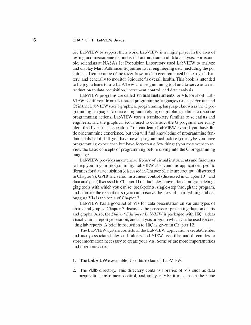
When you launch LabVIEW by double-clicking on its icon, the startup screenappears as in Figure 1.1.
Click here for more quick tips.
Open a new VI.Find and openan existing VI.
Search LabVIEWexamples.Launch an online tutorial.
Exits the LabVIEW application.(QUIT on Macintosh)
FIGURE 1.1The startup screen.
8 CHAPTER 1 LabVIEW Basics
!Throughout this book, use the left mouse button (if you have one) unless we
specifically tell you to use the right one.
At the beginning of each LabVIEW session the startup screen will containa small box at the lower left hand corner that you can check if you want to startup without showing the start screen. If you choose this option, LabVIEW willalways open up with a new VI named Untitled 1.vi rather than with the startupscreen.
The startup screen includes a new quick tip each session. You can view moretips by clicking the Next button. After the LabVIEW session starts (for example,after you have opened a VI) a switch will appear at bottom of the startup screenwindow that lets you choose whether to see this large version of the startup screenor an abbreviated window with just the options to exit LabVIEW, open an exist-ing VI, or create a new VI.
Searchingthe
LabVIEWExamples
In this exercise you will search through the list of example VIs and demon-strations that are included with the Student Edition of LabVIEW. Open the Lab-VIEW application and get to the startup screen. The search begins at the Lab-VIEW startup screen by clicking on the Search Examples button, as shown inFigure 1.1.
After initiating the search, the LabVIEW examples shown are listed by cat-egory:
Fundamentals
I/O Interfaces
Measurements
Communication
Advanced
Demonstrations
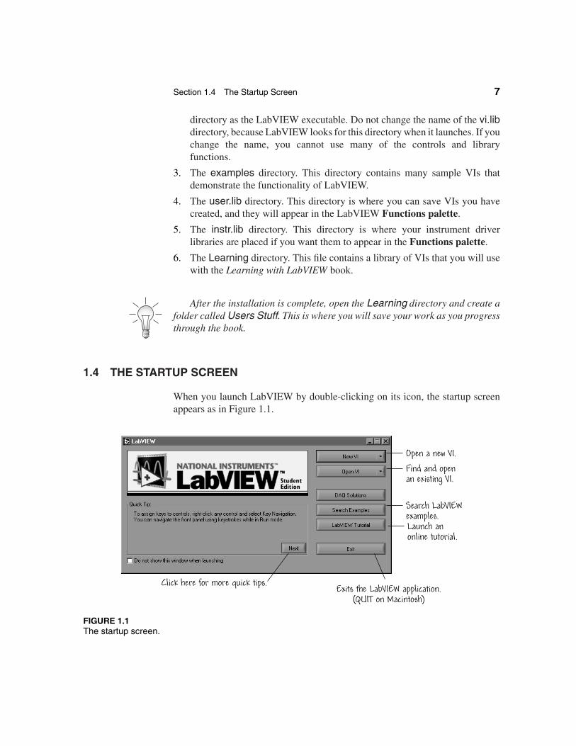
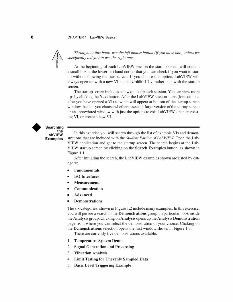
The six categories, shown in Figure 1.2 include many examples. In this exercise,you will pursue a search in the Demonstrations group. In particular, look insidethe Analysis group. Clicking on Analysis opens up the Analysis Demonstrationpage from where you can select the demonstration of your choice. Clicking onthe Demonstrations selection opens the first window shown in Figure 1.3.
There are currently five demonstrations available:
1. Temperature System Demo
2. Signal Generation and Processing
3. Vibration Analysis
4. Limit Testing for Unevenly Sampled Data
5. Basic Level Triggering Example
Section 1.4 The Startup Screen 9
SelectDemonstrations.
FIGURE 1.2LabVIEW examples.
Select TemperatureSystem Demo.
Select Analysis.
FIGURE 1.3The Analysis Demonstrations screen.
10 CHAPTER 1 LabVIEW Basics
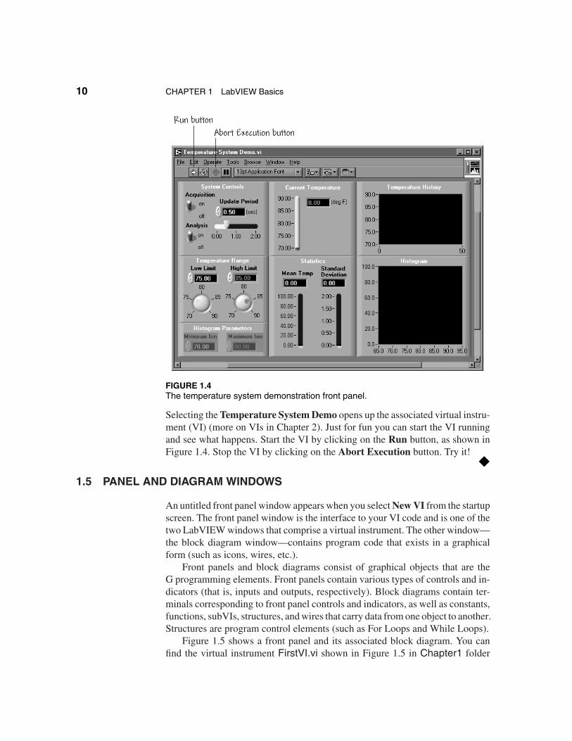
Run buttonAbort Execution button
FIGURE 1.4The temperature system demonstration front panel.
Selecting the Temperature System Demo opens up the associated virtual instru-ment (VI) (more on VIs in Chapter 2). Just for fun you can start the VI runningand see what happens. Start the VI by clicking on the Run button, as shown inFigure 1.4. Stop the VI by clicking on the Abort Execution button. Try it!
1.5 PANEL AND DIAGRAM WINDOWS
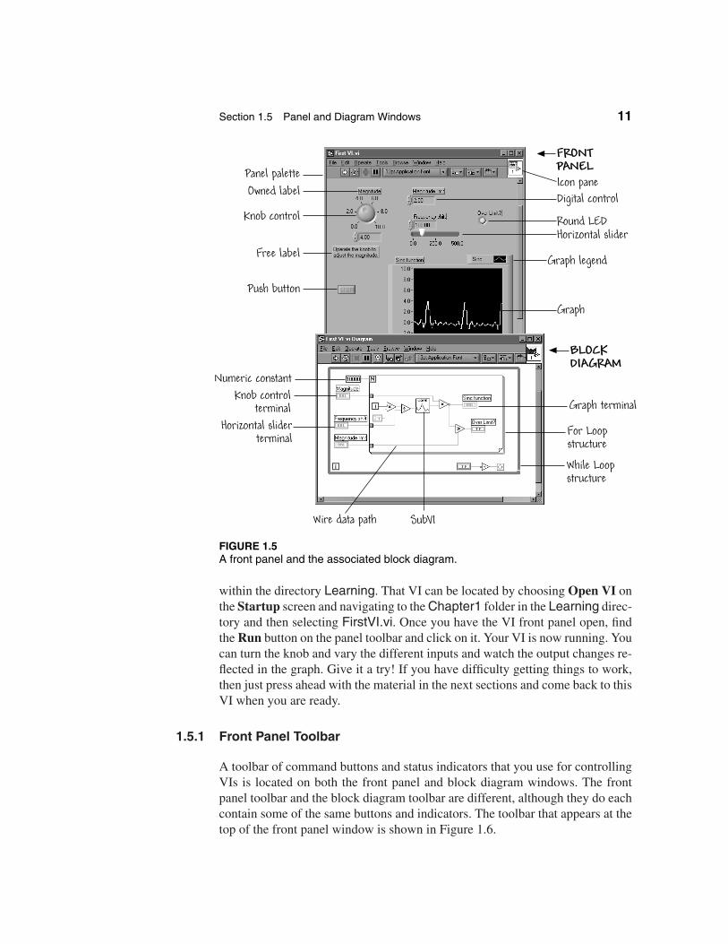
An untitled front panel window appears when you select New VI from the startupscreen. The front panel window is the interface to your VI code and is one of thetwo LabVIEW windows that comprise a virtual instrument. The other window—the block diagram window—contains program code that exists in a graphicalform (such as icons, wires, etc.).
Front panels and block diagrams consist of graphical objects that are theG programming elements. Front panels contain various types of controls and in-dicators (that is, inputs and outputs, respectively). Block diagrams contain ter-minals corresponding to front panel controls and indicators, as well as constants,functions, subVIs, structures, and wires that carry data from one object to another.Structures are program control elements (such as For Loops and While Loops).
Figure 1.5 shows a front panel and its associated block diagram. You canfind the virtual instrument FirstVI.vi shown in Figure 1.5 in Chapter1 folder
Section 1.5 Panel and Diagram Windows 11
Panel palette
Knob controlDigital control
Free label
Icon paneOwned label
Round LED
Push button
Graph legend
Graph
BLOCK DIAGRAM
Knob controlterminal
Numeric constant
While Loopstructure
For Loopstructure
Graph terminal
Horizontal slider
Horizontal sliderterminal
FRONTPANEL
Wire data path SubVI
FIGURE 1.5A front panel and the associated block diagram.
within the directory Learning. That VI can be located by choosing Open VI onthe Startup screen and navigating to the Chapter1 folder in the Learning direc-tory and then selecting FirstVI.vi. Once you have the VI front panel open, findthe Run button on the panel toolbar and click on it. Your VI is now running. Youcan turn the knob and vary the different inputs and watch the output changes re-flected in the graph. Give it a try! If you have difficulty getting things to work,then just press ahead with the material in the next sections and come back to thisVI when you are ready.
1.5.1 Front Panel Toolbar
A toolbar of command buttons and status indicators that you use for controllingVIs is located on both the front panel and block diagram windows. The frontpanel toolbar and the block diagram toolbar are different, although they do eachcontain some of the same buttons and indicators. The toolbar that appears at thetop of the front panel window is shown in Figure 1.6.
12 CHAPTER 1 LabVIEW Basics
Changes to
Run
Continuous run
AbortExecution
Pause
Alignment ring
Distribution ring
Reorder objects
Font ring
If the VI hascompilation errors.
If one of the VI callers is running at the top level.
If the VI is a top level VI.
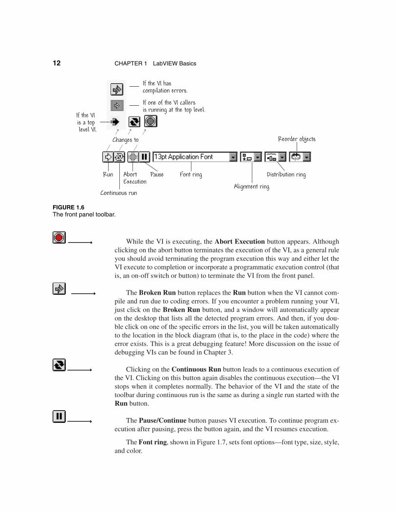
FIGURE 1.6The front panel toolbar.
While the VI is executing, the Abort Execution button appears. Althoughclicking on the abort button terminates the execution of the VI, as a general ruleyou should avoid terminating the program execution this way and either let theVI execute to completion or incorporate a programmatic execution control (thatis, an on-off switch or button) to terminate the VI from the front panel.
The Broken Run button replaces the Run button when the VI cannot com-pile and run due to coding errors. If you encounter a problem running your VI,just click on the Broken Run button, and a window will automatically appearon the desktop that lists all the detected program errors. And then, if you dou-ble click on one of the specific errors in the list, you will be taken automaticallyto the location in the block diagram (that is, to the place in the code) where theerror exists. This is a great debugging feature! More discussion on the issue ofdebugging VIs can be found in Chapter 3.
Clicking on the Continuous Run button leads to a continuous execution ofthe VI. Clicking on this button again disables the continuous execution—the VIstops when it completes normally. The behavior of the VI and the state of thetoolbar during continuous run is the same as during a single run started with theRun button.
The Pause/Continue button pauses VI execution. To continue program ex-ecution after pausing, press the button again, and the VI resumes execution.
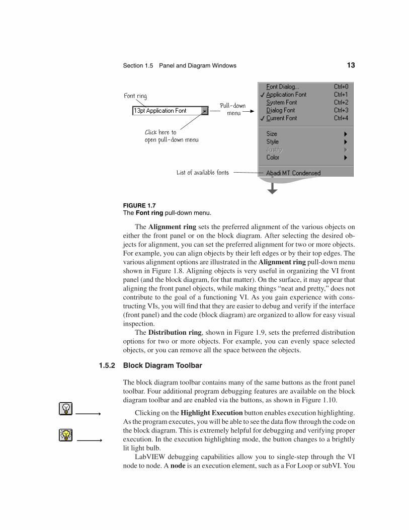
The Font ring, shown in Figure 1.7, sets font options—font type, size, style,and color.
Section 1.5 Panel and Diagram Windows 13
List of available fonts
Pull-down menu
Font ring
Click here toopen pull-down menu
FIGURE 1.7The Font ring pull-down menu.
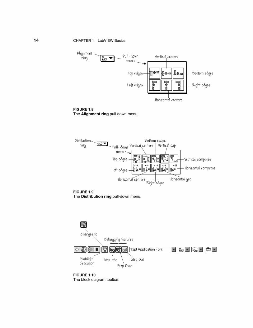
The Alignment ring sets the preferred alignment of the various objects oneither the front panel or on the block diagram. After selecting the desired ob-jects for alignment, you can set the preferred alignment for two or more objects.For example, you can align objects by their left edges or by their top edges. Thevarious alignment options are illustrated in the Alignment ring pull-down menushown in Figure 1.8. Aligning objects is very useful in organizing the VI frontpanel (and the block diagram, for that matter). On the surface, it may appear thataligning the front panel objects, while making things “neat and pretty,” does notcontribute to the goal of a functioning VI. As you gain experience with cons-tructing VIs, you will find that they are easier to debug and verify if the interface(front panel) and the code (block diagram) are organized to allow for easy visualinspection.
The Distribution ring, shown in Figure 1.9, sets the preferred distributionoptions for two or more objects. For example, you can evenly space selectedobjects, or you can remove all the space between the objects.
1.5.2 Block Diagram Toolbar
The block diagram toolbar contains many of the same buttons as the front paneltoolbar. Four additional program debugging features are available on the blockdiagram toolbar and are enabled via the buttons, as shown in Figure 1.10.
Clicking on the Highlight Execution button enables execution highlighting.As the program executes, you will be able to see the data flow through the code onthe block diagram. This is extremely helpful for debugging and verifying properexecution. In the execution highlighting mode, the button changes to a brightlylit light bulb.
LabVIEW debugging capabilities allow you to single-step through the VInode to node. A node is an execution element, such as a For Loop or subVI. You
14 CHAPTER 1 LabVIEW Basics
Alignmentring Pull-down
menuVertical centers
Right edges
Horizontal centers
Left edges
Bottom edgesTop edges
FIGURE 1.8The Alignment ring pull-down menu.
Distibutionring Pull-down
menu
Top edges
Left edges
Vertical centersBottom edges
Vertical gap
Vertical compress
Horizontal compress
Horizontal gapRight edges
Horizontal centers
FIGURE 1.9The Distribution ring pull-down menu.
Changes toDebugging features
HighlightExecution
Step IntoStep Over
Step Out
FIGURE 1.10The block diagram toolbar.
Section 1.6 Short Cut Menus 15
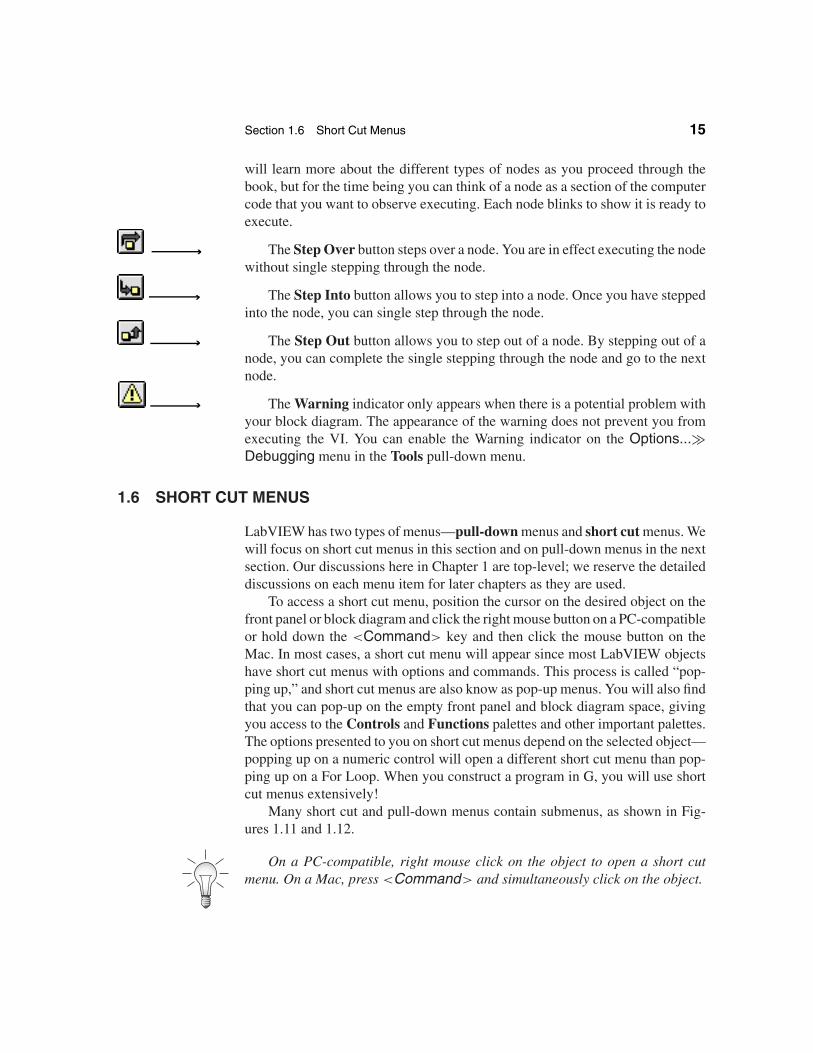
will learn more about the different types of nodes as you proceed through thebook, but for the time being you can think of a node as a section of the computercode that you want to observe executing. Each node blinks to show it is ready toexecute.
The Step Over button steps over a node. You are in effect executing the nodewithout single stepping through the node.
The Step Into button allows you to step into a node. Once you have steppedinto the node, you can single step through the node.
The Step Out button allows you to step out of a node. By stepping out of anode, you can complete the single stepping through the node and go to the nextnode.
The Warning indicator only appears when there is a potential problem withyour block diagram. The appearance of the warning does not prevent you fromexecuting the VI. You can enable the Warning indicator on the Options...�Debugging menu in the Tools pull-down menu.
1.6 SHORT CUT MENUS
LabVIEW has two types of menus—pull-down menus and short cut menus. Wewill focus on short cut menus in this section and on pull-down menus in the nextsection. Our discussions here in Chapter 1 are top-level; we reserve the detaileddiscussions on each menu item for later chapters as they are used.
To access a short cut menu, position the cursor on the desired object on thefront panel or block diagram and click the right mouse button on a PC-compatibleor hold down the <Command> key and then click the mouse button on theMac. In most cases, a short cut menu will appear since most LabVIEW objectshave short cut menus with options and commands. This process is called “pop-ping up,” and short cut menus are also know as pop-up menus. You will also findthat you can pop-up on the empty front panel and block diagram space, givingyou access to the Controls and Functions palettes and other important palettes.The options presented to you on short cut menus depend on the selected object—popping up on a numeric control will open a different short cut menu than pop-ping up on a For Loop. When you construct a program in G, you will use shortcut menus extensively!
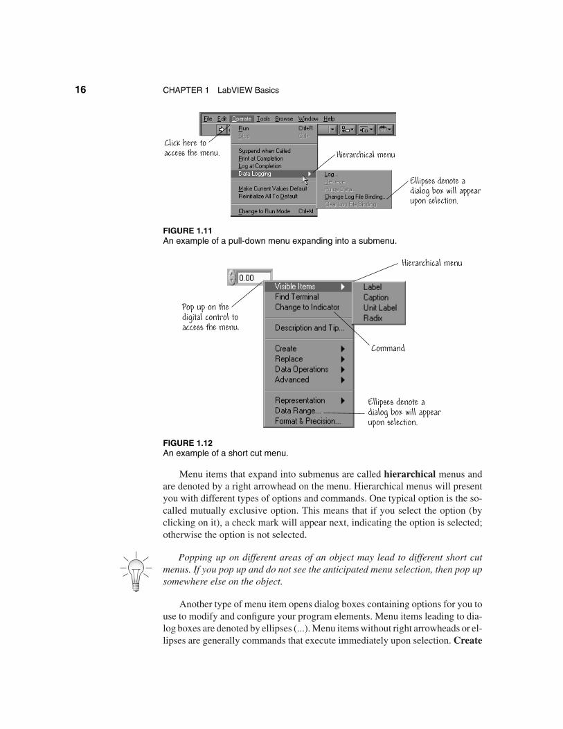
Many short cut and pull-down menus contain submenus, as shown in Fig-ures 1.11 and 1.12.
On a PC-compatible, right mouse click on the object to open a short cutmenu. On a Mac, press <Command> and simultaneously click on the object.
16 CHAPTER 1 LabVIEW Basics
Hierarchical menu
Ellipses denote a dialog box will appearupon selection.
Click here to access the menu.
FIGURE 1.11An example of a pull-down menu expanding into a submenu.
Pop up on thedigital control toaccess the menu.
Hierarchical menu
Ellipses denote a dialog box will appearupon selection.
Command
FIGURE 1.12An example of a short cut menu.
Menu items that expand into submenus are called hierarchical menus andare denoted by a right arrowhead on the menu. Hierarchical menus will presentyou with different types of options and commands. One typical option is the so-called mutually exclusive option. This means that if you select the option (byclicking on it), a check mark will appear next, indicating the option is selected;otherwise the option is not selected.
Popping up on different areas of an object may lead to different short cutmenus. If you pop up and do not see the anticipated menu selection, then pop upsomewhere else on the object.
Another type of menu item opens dialog boxes containing options for you touse to modify and configure your program elements. Menu items leading to dia-log boxes are denoted by ellipses (...). Menu items without right arrowheads or el-lipses are generally commands that execute immediately upon selection. Create
Section 1.7 Pull-Down Menus 17
Constant is an example of a command that appears in many short cut menus. Insome instances, commands are replaced in the menu by their inverse commandswhen selected. For example, after you choose Change to Indicator, the menuselection is replaced by Change to Control.
1.7 PULL-DOWN MENUS
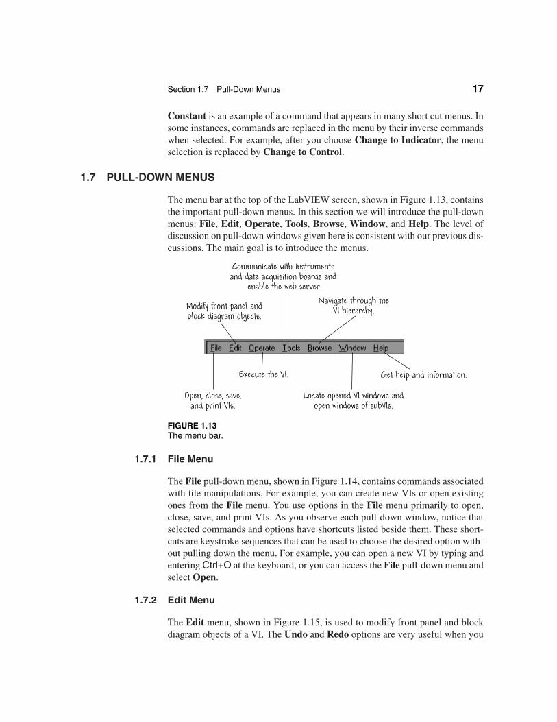
The menu bar at the top of the LabVIEW screen, shown in Figure 1.13, containsthe important pull-down menus. In this section we will introduce the pull-downmenus: File, Edit, Operate, Tools, Browse, Window, and Help. The level ofdiscussion on pull-down windows given here is consistent with our previous dis-cussions. The main goal is to introduce the menus.
Open, close, save,and print VIs.
Modify front panel andblock diagram objects.
Execute the VI.
Navigate through theVI hierarchy.
Locate opened VI windows andopen windows of subVIs.
Get help and information.
Communicate with instruments and data acquisition boards and
enable the web server.
FIGURE 1.13The menu bar.
1.7.1 File Menu
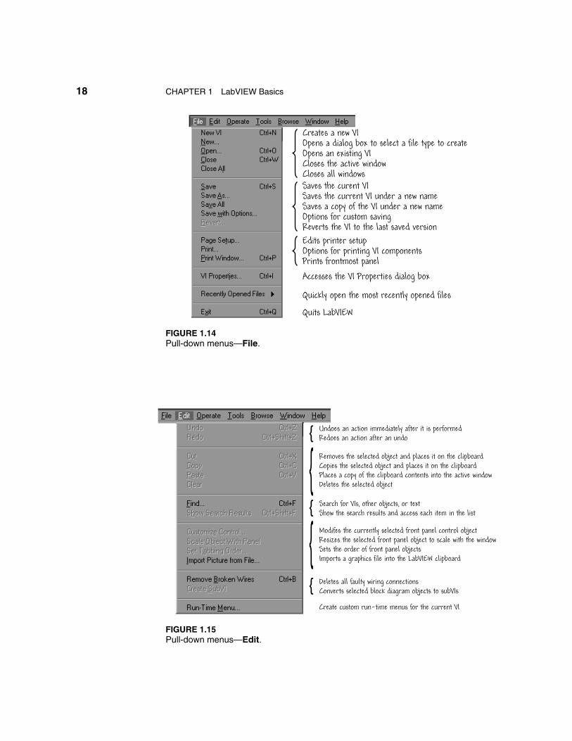
The File pull-down menu, shown in Figure 1.14, contains commands associatedwith file manipulations. For example, you can create new VIs or open existingones from the File menu. You use options in the File menu primarily to open,close, save, and print VIs. As you observe each pull-down window, notice thatselected commands and options have shortcuts listed beside them. These short-cuts are keystroke sequences that can be used to choose the desired option with-out pulling down the menu. For example, you can open a new VI by typing andentering Ctrl+O at the keyboard, or you can access the File pull-down menu andselect Open.
1.7.2 Edit Menu
The Edit menu, shown in Figure 1.15, is used to modify front panel and blockdiagram objects of a VI. The Undo and Redo options are very useful when you
18 CHAPTER 1 LabVIEW Basics
Creates a new VIOpens a dialog box to select a file type to createOpens an existing VICloses the active windowCloses all windowsSaves the curent VISaves the current VI under a new nameSaves a copy of the VI under a new nameOptions for custom savingReverts the VI to the last saved version
Quits LabVIEW
Edits printer setupOptions for printing VI componentsPrints frontmost panel
Accesses the VI Properties dialog box
Quickly open the most recently opened files
FIGURE 1.14Pull-down menus—File.
Removes the selected object and places it on the clipboardCopies the selected object and places it on the clipboardPlaces a copy of the clipboard contents into the active windowDeletes the selected object
Deletes all faulty wiring connectionsConverts selected block diagram objects to subVIs
Search for VIs, other objects, or textShow the search results and access each item in the list
Undoes an action immediately after it is performedRedoes an action after an undo}}
Modifes the currently selected front panel control objectResizes the selected front panel object to scale with the window Sets the order of front panel objectsImports a graphics file into the LabVIEW clipboard
}}
}
Create custom run-time menus for the current VI
FIGURE 1.15Pull-down menus—Edit.
Section 1.7 Pull-Down Menus 19
are editing because it allows you to undo an action after it is performed, and onceyou undo an action you can redo it. By default, the maximum number of undosteps per VI is 8—you can increase or decrease this number if desired.
1.7.3 Operate Menu
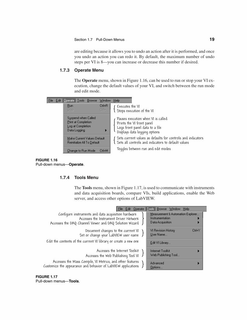
The Operate menu, shown in Figure 1.16, can be used to run or stop your VI ex-ecution, change the default values of your VI, and switch between the run modeand edit mode.
Executes the VIStops execution of the VI
Pauses execution when VI is calledPrints the VI front panelLogs front panel data to a fileDisplays data logging optionsSets current values as defaults for controls and indicatorsSets all controls and indicators to default valuesToggles between run and edit modes
FIGURE 1.16Pull-down menus—Operate.
1.7.4 Tools Menu
The Tools menu, shown in Figure 1.17, is used to communicate with instrumentsand data acquisition boards, compare VIs, build applications, enable the Webserver, and access other options of LabVIEW.
Configure instruments and data acquisition hardwareAccesses the Instrument Driver Network
Accesses the DAQ Channel Viewer and DAQ Solution Wizard
Document changes to the current VISet or change your LabVIEW user name
Edit the contents of the current VI library or create a new one
Accesses the Web Publishing Tool VIAccesses the Mass Compile, VI Metrics, and other features
Customize the appearance and behavior of LabVIEW applications
Accesses the Internet Toolkit
FIGURE 1.17Pull-down menus—Tools.
20 CHAPTER 1 LabVIEW Basics
An important link is to the main National Instruments website, where you canobtain general information about the company and its products. If you use Lab-VIEW to control external instruments, you will be interested in the InstrumentDriver Network... link, which connects you to over 600 LabVIEW-ready instru-ment drivers. This can be found in the Tools�Instrumentation hierarchichalmenu. Refer to Chapter 10 for more information on instrument drivers.
1.7.5 Browse Menu
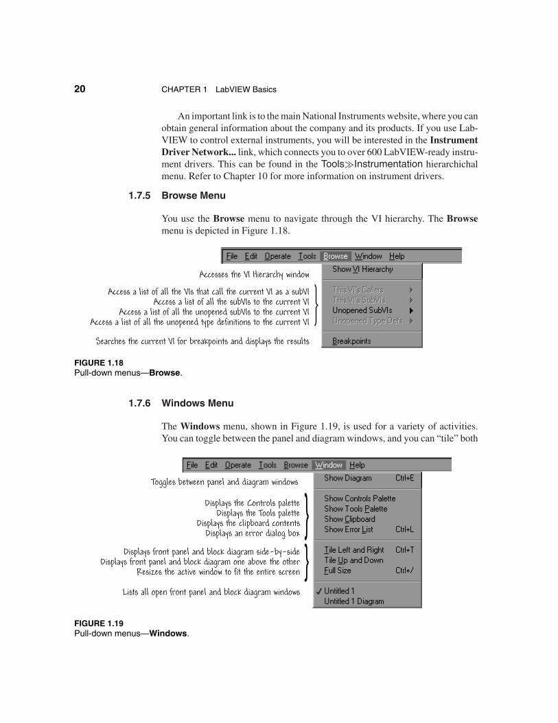
You use the Browse menu to navigate through the VI hierarchy. The Browsemenu is depicted in Figure 1.18.
Accesses the VI Hierarchy window
Access a list of all the VIs that call the current VI as a subVIAccess a list of all the subVIs to the current VI
Access a list of all the unopened subVIs to the current VIAccess a list of all the unopened type definitions to the current VI
Searches the current VI for breakpoints and displays the results
FIGURE 1.18Pull-down menus—Browse.
1.7.6 Windows Menu
The Windows menu, shown in Figure 1.19, is used for a variety of activities.You can toggle between the panel and diagram windows, and you can “tile” both
}}
Toggles between panel and diagram windows
Displays the Controls paletteDisplays the Tools palette
Displays the clipboard contentsDisplays an error dialog box
Displays front panel and block diagram side-by-sideDisplays front panel and block diagram one above the other
Resizes the active window to fit the entire screen
Lists all open front panel and block diagram windows
FIGURE 1.19Pull-down menus—Windows.
Section 1.8 Palettes 21
windows so you can see them at the same time (one above the other or side-by-side). All the open VIs are listed in the menu (at the bottom), and you can switchbetween the open VIs. Also, if you want to show the palettes on the desktop, youcan use the Windows menu to select either (or both) palettes (more on palettesin the next section).
1.7.7 Help Menu
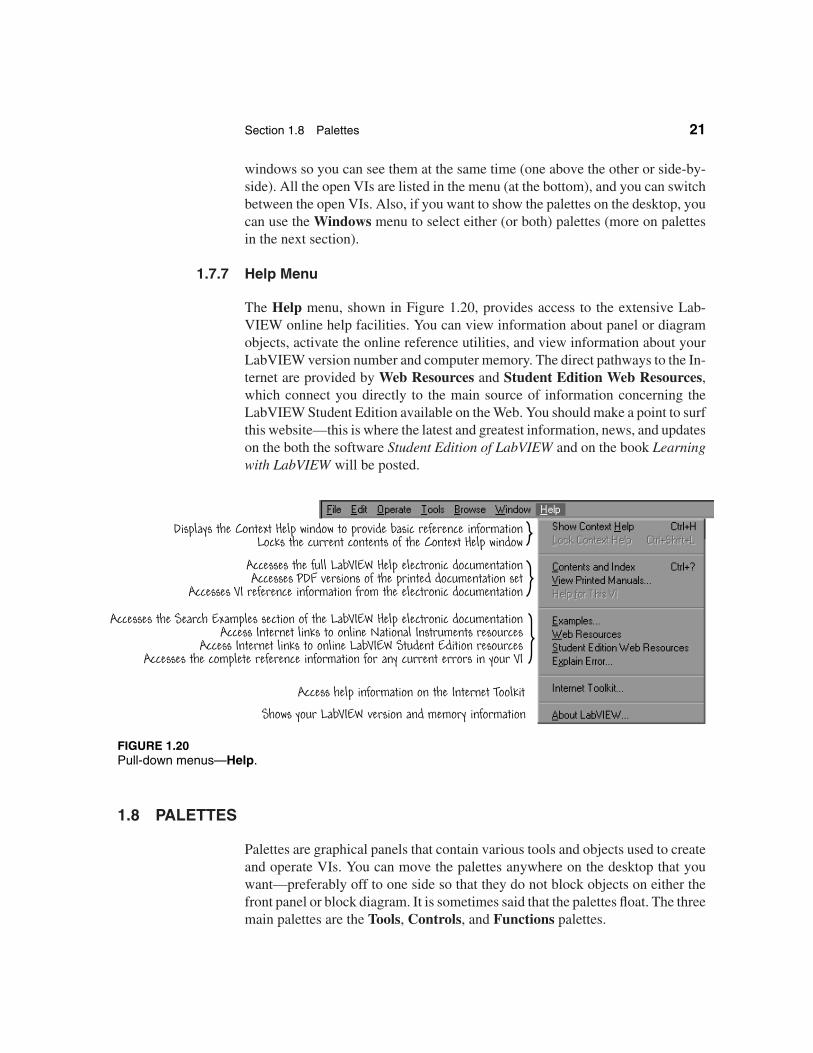
The Help menu, shown in Figure 1.20, provides access to the extensive Lab-VIEW online help facilities. You can view information about panel or diagramobjects, activate the online reference utilities, and view information about yourLabVIEW version number and computer memory. The direct pathways to the In-ternet are provided by Web Resources and Student Edition Web Resources,which connect you directly to the main source of information concerning theLabVIEW Student Edition available on the Web. You should make a point to surfthis website—this is where the latest and greatest information, news, and updateson the both the software Student Edition of LabVIEW and on the book Learningwith LabVIEW will be posted.
Displays the Context Help window to provide basic reference informationLocks the current contents of the Context Help window
Accesses the Search Examples section of the LabVIEW Help electronic documentationAccess Internet links to online National Instruments resources
Access Internet links to online LabVIEW Student Edition resourcesAccesses the complete reference information for any current errors in your VI
Accesses the full LabVIEW Help electronic documentationAccesses PDF versions of the printed documentation set
Accesses VI reference information from the electronic documentation
Shows your LabVIEW version and memory information
Access help information on the Internet Toolkit
FIGURE 1.20Pull-down menus—Help.
1.8 PALETTES
Palettes are graphical panels that contain various tools and objects used to createand operate VIs. You can move the palettes anywhere on the desktop that youwant—preferably off to one side so that they do not block objects on either thefront panel or block diagram. It is sometimes said that the palettes float. The threemain palettes are the Tools, Controls, and Functions palettes.
22 CHAPTER 1 LabVIEW Basics
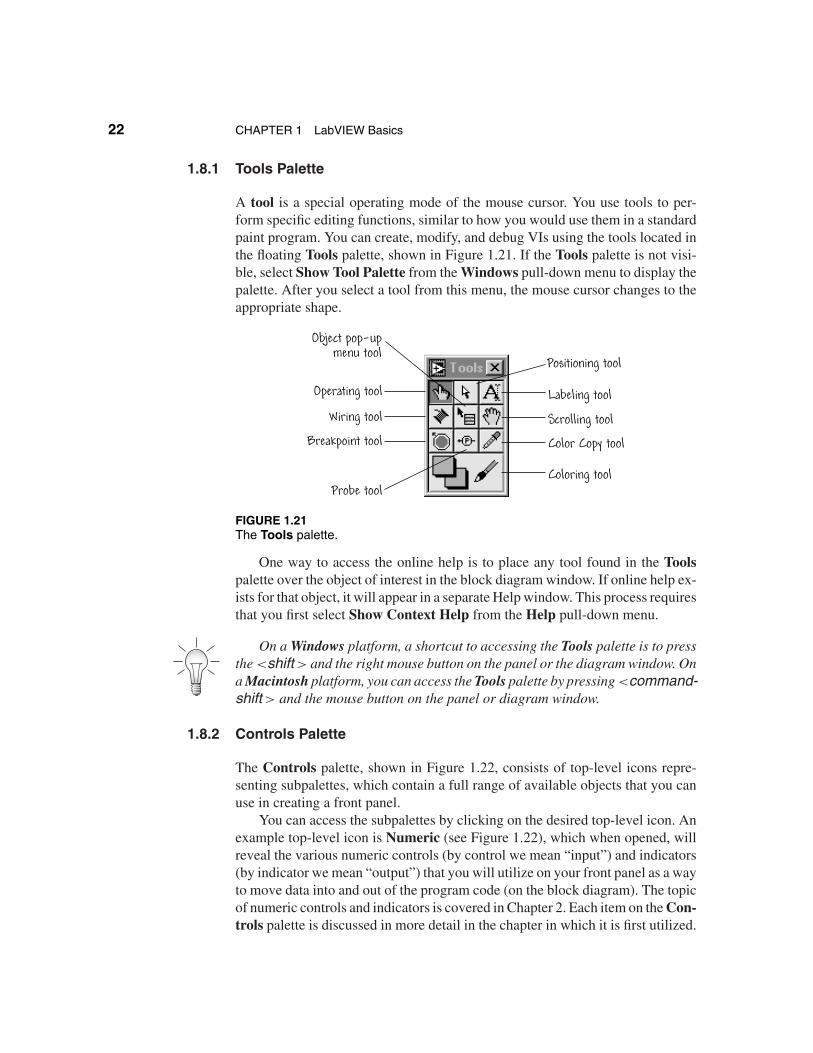
1.8.1 Tools Palette
A tool is a special operating mode of the mouse cursor. You use tools to per-form specific editing functions, similar to how you would use them in a standardpaint program. You can create, modify, and debug VIs using the tools located inthe floating Tools palette, shown in Figure 1.21. If the Tools palette is not visi-ble, select Show Tool Palette from the Windows pull-down menu to display thepalette. After you select a tool from this menu, the mouse cursor changes to theappropriate shape.
Object pop-upmenu tool
Operating tool
Wiring tool
Breakpoint tool
Probe tool
Positioning tool
Labeling tool
Scrolling tool
Color Copy tool
Coloring tool
FIGURE 1.21The Tools palette.
One way to access the online help is to place any tool found in the Toolspalette over the object of interest in the block diagram window. If online help ex-ists for that object, it will appear in a separate Help window. This process requiresthat you first select Show Context Help from the Help pull-down menu.
On a Windows platform, a shortcut to accessing the Tools palette is to pressthe <shift > and the right mouse button on the panel or the diagram window. Ona Macintosh platform, you can access the Tools palette by pressing <command-shift > and the mouse button on the panel or diagram window.
1.8.2 Controls Palette
The Controls palette, shown in Figure 1.22, consists of top-level icons repre-senting subpalettes, which contain a full range of available objects that you canuse in creating a front panel.
You can access the subpalettes by clicking on the desired top-level icon. Anexample top-level icon is Numeric (see Figure 1.22), which when opened, willreveal the various numeric controls (by control we mean “input”) and indicators(by indicator we mean “output”) that you will utilize on your front panel as a wayto move data into and out of the program code (on the block diagram). The topicof numeric controls and indicators is covered in Chapter 2. Each item on the Con-trols palette is discussed in more detail in the chapter in which it is first utilized.
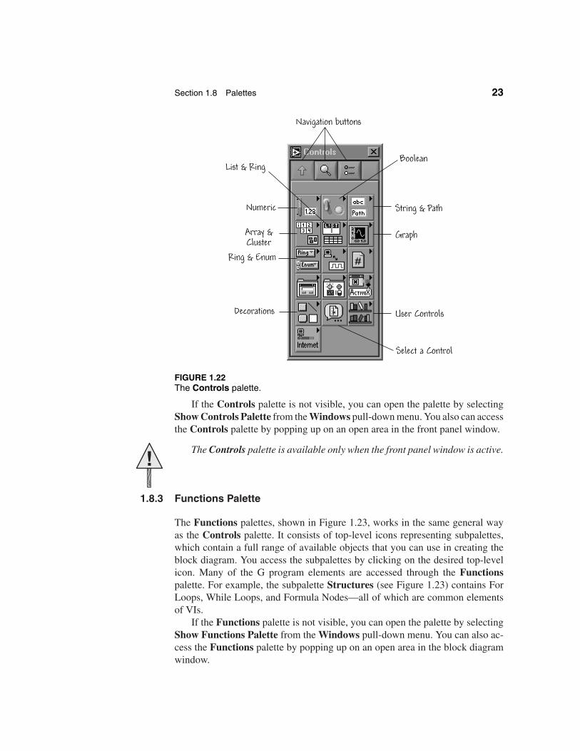
Section 1.8 Palettes 23
Array &Cluster
Select a Control
Boolean
Numeric
List & Ring
Ring & Enum
String & Path
Graph
Decorations User Controls
Navigation buttons
FIGURE 1.22The Controls palette.
If the Controls palette is not visible, you can open the palette by selectingShow Controls Palette from the Windows pull-down menu. You also can accessthe Controls palette by popping up on an open area in the front panel window.
!The Controls palette is available only when the front panel window is active.
1.8.3 Functions Palette
The Functions palettes, shown in Figure 1.23, works in the same general wayas the Controls palette. It consists of top-level icons representing subpalettes,which contain a full range of available objects that you can use in creating theblock diagram. You access the subpalettes by clicking on the desired top-levelicon. Many of the G program elements are accessed through the Functionspalette. For example, the subpalette Structures (see Figure 1.23) contains ForLoops, While Loops, and Formula Nodes—all of which are common elementsof VIs.
If the Functions palette is not visible, you can open the palette by selectingShow Functions Palette from the Windows pull-down menu. You can also ac-cess the Functions palette by popping up on an open area in the block diagramwindow.
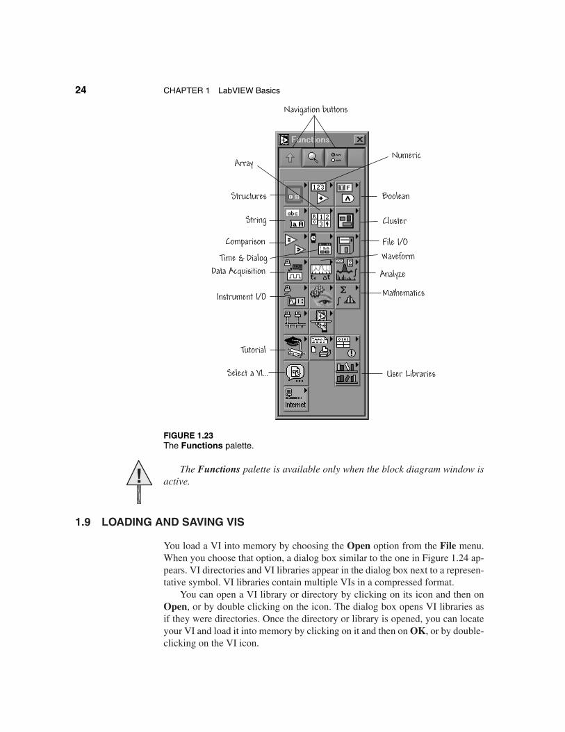
24 CHAPTER 1 LabVIEW Basics
Boolean
Cluster
File I/OWaveform
Data Acquisition
Mathematics
Select a VI...
Tutorial
Structures
String
Comparison
Time & Dialog
Analyze
Instrument I/O
ArrayNumeric
User Libraries
Navigation buttons
FIGURE 1.23The Functions palette.
! The Functions palette is available only when the block diagram window isactive.
1.9 LOADING AND SAVING VIS
You load a VI into memory by choosing the Open option from the File menu.When you choose that option, a dialog box similar to the one in Figure 1.24 ap-pears. VI directories and VI libraries appear in the dialog box next to a represen-tative symbol. VI libraries contain multiple VIs in a compressed format.
You can open a VI library or directory by clicking on its icon and then onOpen, or by double clicking on the icon. The dialog box opens VI libraries asif they were directories. Once the directory or library is opened, you can locateyour VI and load it into memory by clicking on it and then on OK, or by double-clicking on the VI icon.
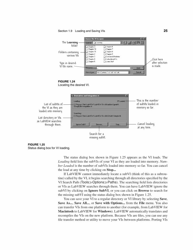
Section 1.9 Loading and Saving VIs 25
Folders containingvarious VIs
Click hereafter selectionis made.
Type in desiredVI file name.
The Learningfolder
FIGURE 1.24Locating the desired VI.
List directory or VIsas LabVIEW searches
through them. Cancel loadingat any time.
Search for a missing subVI.
List of subVIs ofthe VI as they are
loaded into memory.
This is the numberof subVIs loaded inmemory so far.
FIGURE 1.25Status dialog box for VI loading.
The status dialog box shown in Figure 1.25 appears as the VI loads. TheLoading field lists the subVIs of your VI as they are loaded into memory. Num-ber Loaded is the number of subVIs loaded into memory so far. You can cancelthe load at any time by clicking on Stop...
If LabVIEW cannot immediately locate a subVI (think of this as a subrou-tine) called by the VI, it begins searching through all directories specified by theVI Search Path (Tools�Options�Paths). The searching field lists directoriesor VIs as LabVIEW searches through them. You can have LabVIEW ignore thesubVI by clicking on Ignore SubVI, or you can click on Browse to search forthe missing subVI using the status dialog box shown in Figure 1.25.
You can save your VI to a regular directory or VI library by selecting Save,Save As..., Save All..., or Save with Options... from the File menu. You alsocan transfer VIs from one platform to another (for example, from LabVIEW forMacintosh to LabVIEW for Windows). LabVIEW automatically translates andrecompiles the VIs on the new platform. Because VIs are files, you can use anyfile transfer method or utility to move your VIs between platforms. Porting VIs
26 CHAPTER 1 LabVIEW Basics
over networks using FTP protocol, Z- or X-Modem protocol, and other similarutilities eliminates the need for additional file translation software. If you portyour VIs via magnetic media (such as floppy disks), you will need to use a filetransfer utility (such as MacDisk or Transfer Pro).
1.10 LABVIEW HELP OPTIONS
The two common help options that you will use as you learn about LabVIEWprogramming are the Show Context Help and the Contents and Index. Bothhelp options can be accessed in the Help pull-down menu.
1.10.1 Context Help Window
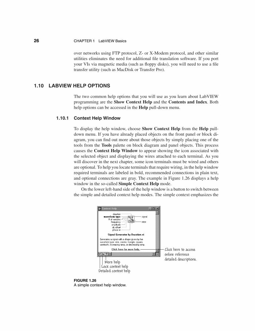
To display the help window, choose Show Context Help from the Help pull-down menu. If you have already placed objects on the front panel or block di-agram, you can find out more about those objects by simply placing one of thetools from the Tools palette on block diagram and panel objects. This processcauses the Context Help Window to appear showing the icon associated withthe selected object and displaying the wires attached to each terminal. As youwill discover in the next chapter, some icon terminals must be wired and othersare optional. To help you locate terminals that require wiring, in the help windowrequired terminals are labeled in bold, recommended connections in plain text,and optional connections are gray. The example in Figure 1.26 displays a helpwindow in the so-called Simple Context Help mode.
On the lower left-hand side of the help window is a button to switch betweenthe simple and detailed context help modes. The simple context emphasizes the
More helpLock context help
Detailed context help
Click here to accessonline referencedetailed descriptions.
FIGURE 1.26A simple context help window.
Section 1.11 Building Blocks: Trajectory Analysis 27
More helpLock context help
Simple context help
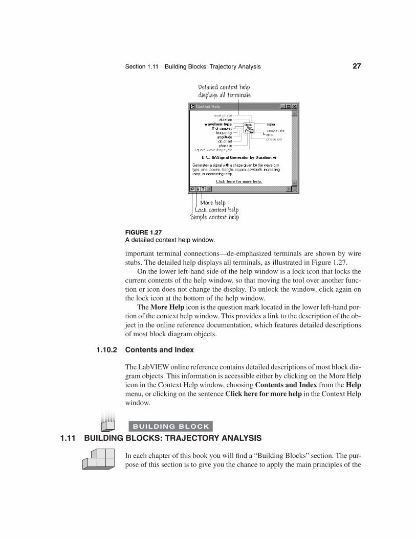
Detailed context helpdisplays all terminals
FIGURE 1.27A detailed context help window.
important terminal connections—de-emphasized terminals are shown by wirestubs. The detailed help displays all terminals, as illustrated in Figure 1.27.
On the lower left-hand side of the help window is a lock icon that locks thecurrent contents of the help window, so that moving the tool over another func-tion or icon does not change the display. To unlock the window, click again onthe lock icon at the bottom of the help window.
The More Help icon is the question mark located in the lower left-hand por-tion of the context help window. This provides a link to the description of the ob-ject in the online reference documentation, which features detailed descriptionsof most block diagram objects.
1.10.2 Contents and Index
The LabVIEW online reference contains detailed descriptions of most block dia-gram objects. This information is accessible either by clicking on the More Helpicon in the Context Help window, choosing Contents and Index from the Helpmenu, or clicking on the sentence Click here for more help in the Context Helpwindow.
1.11
BUILDING BLOCK
BUILDING BLOCKS: TRAJECTORY ANALYSIS
In each chapter of this book you will find a “Building Blocks” section. The pur-pose of this section is to give you the chance to apply the main principles of the
28 CHAPTER 1 LabVIEW Basics
chapter. In some cases the building block exercise of one chapter will continuein the next chapter; in other cases, the exercise will be new. The exercises willbe short, and you will be asked to do all the work!
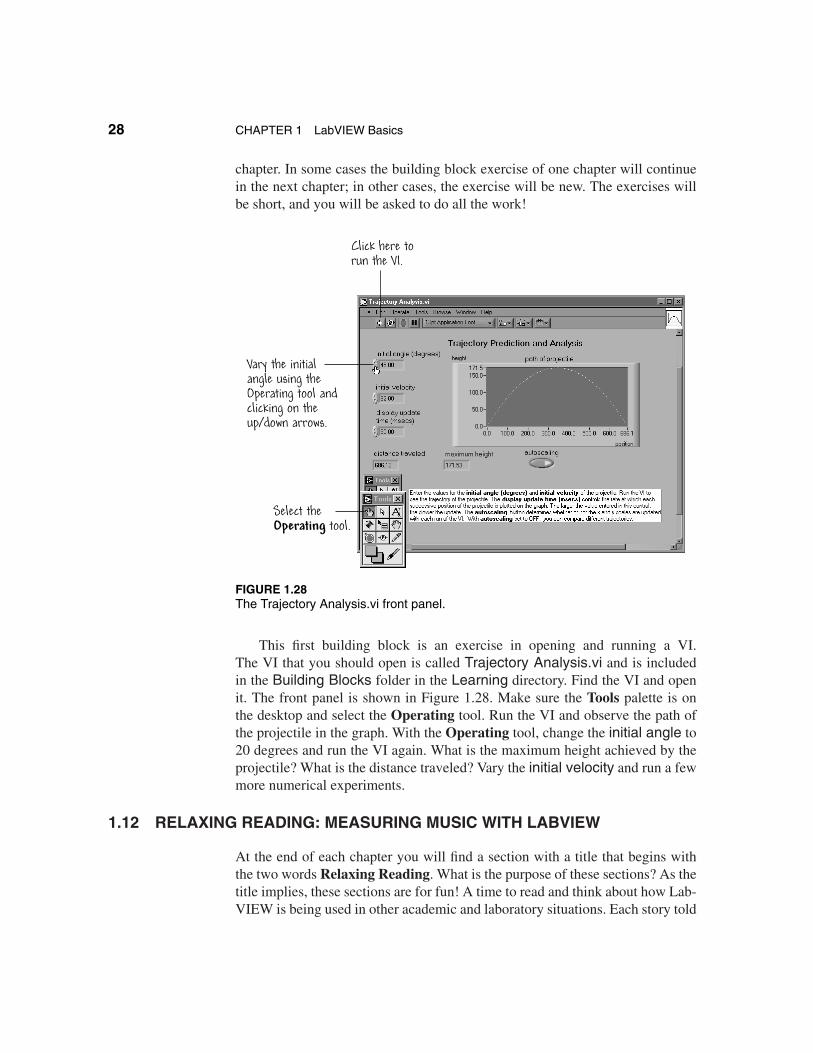
Click here torun the VI.
Vary the initialangle using theOperating tool andclicking on the up/down arrows.
Select theOperating tool.
FIGURE 1.28The Trajectory Analysis.vi front panel.
This first building block is an exercise in opening and running a VI.The VI that you should open is called Trajectory Analysis.vi and is includedin the Building Blocks folder in the Learning directory. Find the VI and openit. The front panel is shown in Figure 1.28. Make sure the Tools palette is onthe desktop and select the Operating tool. Run the VI and observe the path ofthe projectile in the graph. With the Operating tool, change the initial angle to20 degrees and run the VI again. What is the maximum height achieved by theprojectile? What is the distance traveled? Vary the initial velocity and run a fewmore numerical experiments.
1.12 RELAXING READING: MEASURING MUSIC WITH LABVIEW
At the end of each chapter you will find a section with a title that begins withthe two words Relaxing Reading. What is the purpose of these sections? As thetitle implies, these sections are for fun! A time to read and think about how Lab-VIEW is being used in other academic and laboratory situations. Each story told
Section 1.12 Relaxing Reading: Measuring Music with LabVIEW 29
comes from a source of real-world application stories called the User’s Solutionswhich are catalogued by National Instruments and made available on their web-site. Other stories that you will find at the end of the chapters in this book includesolar car racing, exploring the sense of smell, learning analytical chemistry, andmore. If a particular story strikes your fancy, you can read the full-length story onthe NI website, or you can contact the original author of the story at the addressgiven at the end of each section.
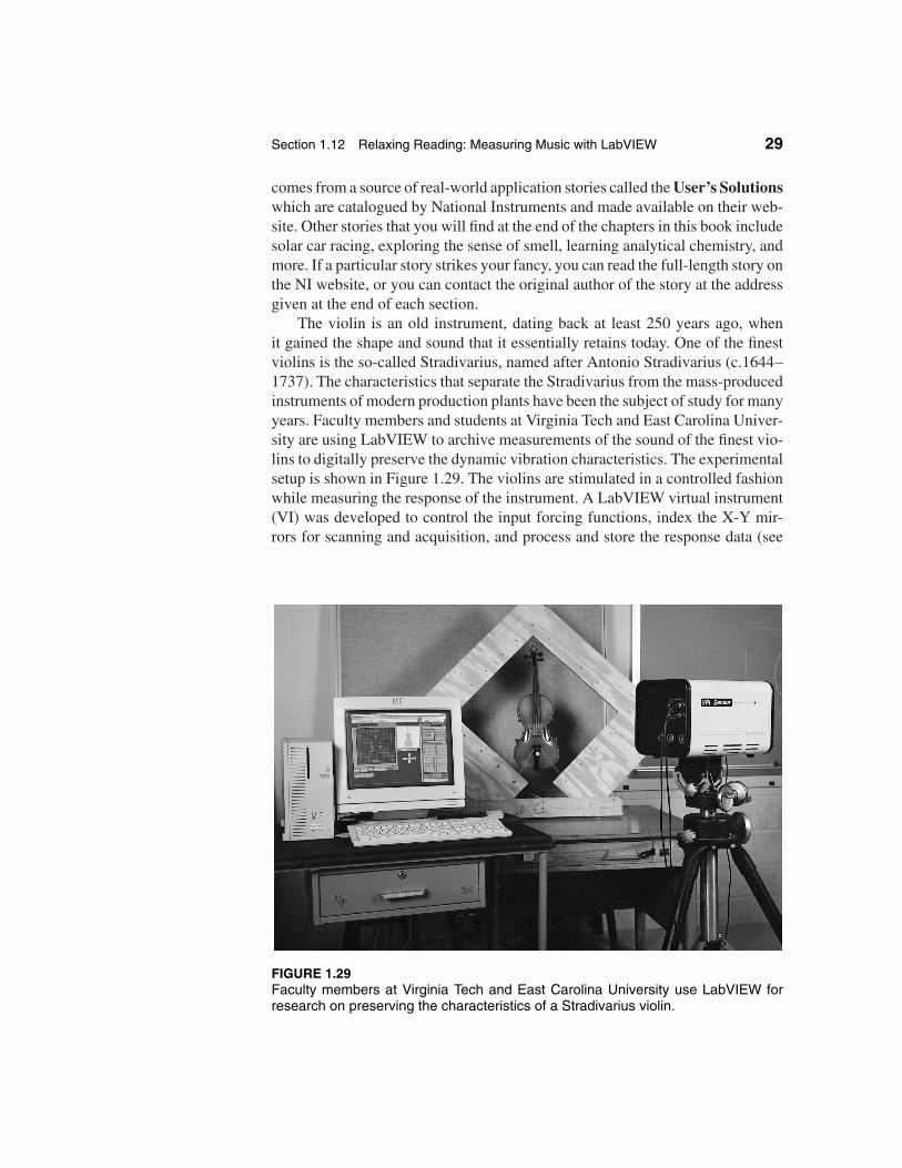
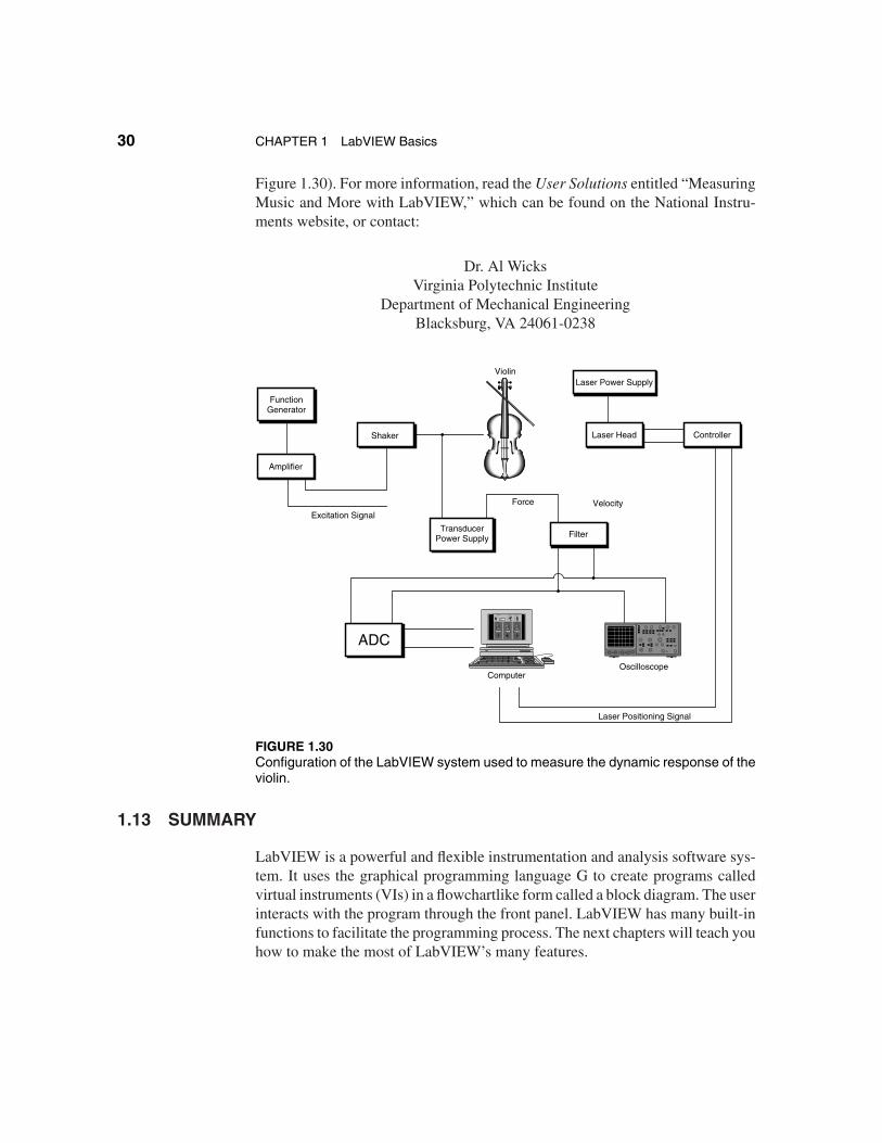
The violin is an old instrument, dating back at least 250 years ago, whenit gained the shape and sound that it essentially retains today. One of the finestviolins is the so-called Stradivarius, named after Antonio Stradivarius (c.1644–1737). The characteristics that separate the Stradivarius from the mass-producedinstruments of modern production plants have been the subject of study for manyyears. Faculty members and students at Virginia Tech and East Carolina Univer-sity are using LabVIEW to archive measurements of the sound of the finest vio-lins to digitally preserve the dynamic vibration characteristics. The experimentalsetup is shown in Figure 1.29. The violins are stimulated in a controlled fashionwhile measuring the response of the instrument. A LabVIEW virtual instrument(VI) was developed to control the input forcing functions, index the X-Y mir-rors for scanning and acquisition, and process and store the response data (see
FIGURE 1.29Faculty members at Virginia Tech and East Carolina University use LabVIEW forresearch on preserving the characteristics of a Stradivarius violin.
30 CHAPTER 1 LabVIEW Basics
Figure 1.30). For more information, read the User Solutions entitled “MeasuringMusic and More with LabVIEW,” which can be found on the National Instru-ments website, or contact:
Dr. Al WicksVirginia Polytechnic Institute
Department of Mechanical EngineeringBlacksburg, VA 24061-0238
TRIGGER TRIG MODE TRIG SOURCE
SLOPELEVEL
1.0000
EXT 2EXT 1CH 2CH 1
AutoNormalSingle
Volts
CHANNEL 1 CHANNEL 2 CHANNEL 3V/DIV V/DIV V/DIV
10.00
MAGNITUDE
20.00 25.00
MAGNITUDE MAGNITUDE
0.000001
0
10
20
50
40
30
0
10
20
50
40
30
0
10
20
50
40
30
0.0010 0.0010
COUPLING DISPLAYCOUPLING
GNDDCAC
GNDDCAC
WFXY
DUALCH 2CH 1
FunctionGenerator
Amplifier
Shaker
Violin
TransducerPower Supply
ADC
Computer
Force
Filter
Oscilloscope
Laser Power Supply
Laser Head Controller
Laser Positioning Signal
VelocityExcitation Signal
FIGURE 1.30Configuration of the LabVIEW system used to measure the dynamic response of theviolin.
1.13 SUMMARY
LabVIEW is a powerful and flexible instrumentation and analysis software sys-tem. It uses the graphical programming language G to create programs calledvirtual instruments (VIs) in a flowchartlike form called a block diagram. The userinteracts with the program through the front panel. LabVIEW has many built-infunctions to facilitate the programming process. The next chapters will teach youhow to make the most of LabVIEW’s many features.
Section 1.13 Summary 31
KEY TERMS
Block diagram: Pictorial representation of a program or algo-rithm. In G, the block diagram, which consists of executable icons,called nodes, and wires that carry data between the nodes, is thesource code for the VI.
Context Help window: Special window that displays the namesand locations of the terminals for a function or subVI, the descrip-tion of controls and indicators, the values of universal constants,and descriptions and data types of control attributes. The windowalso accesses the Online Reference.
Controls palette: Palette containing front panel controls andindicators.
Front panel: The interactive interface of a VI. Modeled from thefront panel of physical instruments, it is composed of switches,slides, meters, graphs, charts, gauges, LEDs, and other controlsand indicators.
Functions palette: Palette containing block diagram structures,constants, and VIs.
Hierarchical menus: Menu items that expand into submenus.
LabVIEW: Laboratory Virtual Instrument EngineeringWorkbench. It is a powerful and flexible instrumentation andanalysis software development application.
Nodes: Execution elements of a block diagram consisting offunctions, structures, and subVIs.
Palette: Menu of pictures that represent possible options.
Pop up: To call up a special menu by clicking an object with theright mouse button (on Windows platforms) or with the commandkey and the mouse button (on Macintosh platforms).
Pull-down menu: Menus accessed from a menu bar. Pull-downmenu options are usually general in nature.
32 CHAPTER 1 LabVIEW Basics
Short cut menu: Menus accessed by popping up, usually on anobject. Menu options pertain to that object specifically.
Tool: A special operating mode of the mouse cursor.
Tools palette: Palette containing tools you can use to edit anddebug front panel and block diagram objects.
Toolbar: Bar containing command buttons to run and debug VIs.
Virtual instrument (VI): Program in LabVIEW; so-called becauseit models the appearance and function of a physical instrument.
EXERCISES
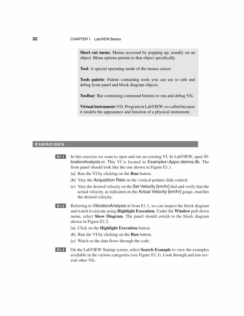
E1.1 In this exercise we want to open and run an existing VI. In LabVIEW, open Vi-brationAnalysis.vi. This VI is located in Examples\Apps\demos.llb. Thefront panel should look like the one shown in Figure E1.1.
(a) Run the VI by clicking on the Run button.
(b) Vary the Acquisition Rate on the vertical pointer slide control.
(c) Vary the desired velocity on the Set Velocity [km/hr] dial and verify that theactual velocity, as indicated on the Actual Velocity [km/hr] gauge, matchesthe desired velocity.
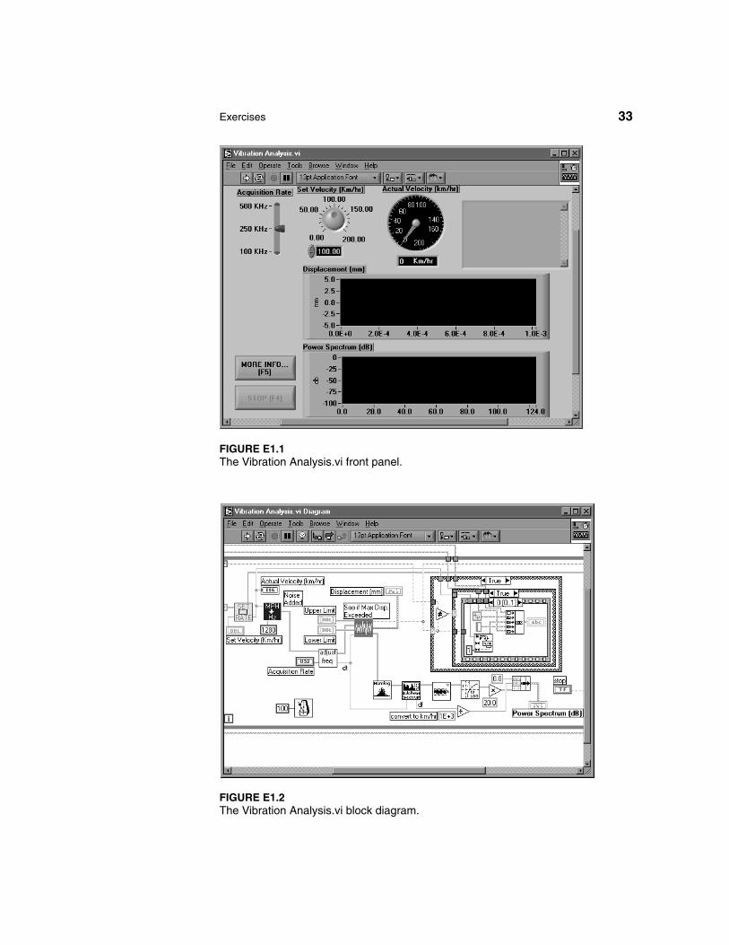
E1.2 Referring to VibrationAnalysis.vi from E1.1, we can inspect the block diagramand watch it execute using Highlight Execution. Under the Window pull-downmenu, select Show Diagram. The panel should switch to the block diagramshown in Figure E1.2.
(a) Click on the Highlight Execution button.
(b) Run the VI by clicking on the Run button.
(c) Watch as the data flows through the code.
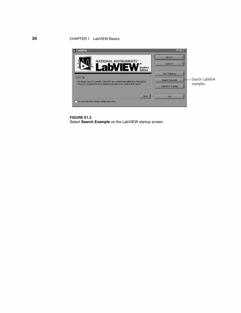
E1.3 On the LabVIEW Startup screen, select Search Example to view the examplesavailable in the various categories (see Figure E1.3). Look through and run sev-eral other VIs.
Exercises 33
FIGURE E1.1The Vibration Analysis.vi front panel.
FIGURE E1.2The Vibration Analysis.vi block diagram.
34 CHAPTER 1 LabVIEW Basics
Search LabVIEWexamples.
FIGURE E1.3Select Search Example on the LabVIEW startup screen.
Problems 35
PROBLEMS
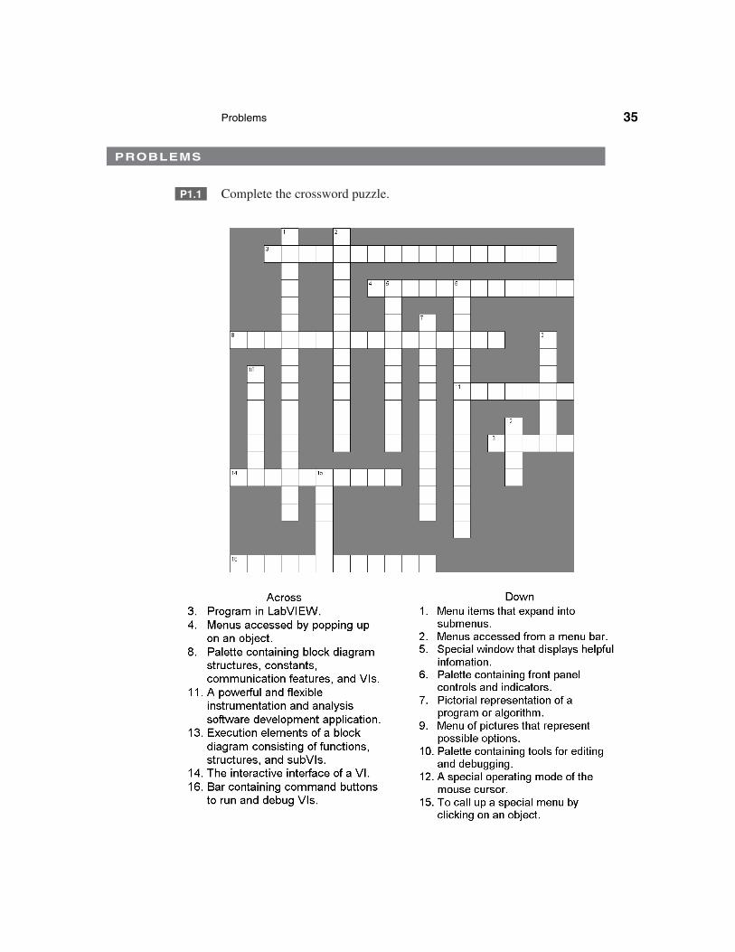
P1.1 Complete the crossword puzzle.
36 CHAPTER 1 LabVIEW Basics
P1.2 In the problem we want to open an existing VI from the Learning directory.You can open the VI by either selecting Open VI from the Startup screen, orif you are already in LabVIEW, you can use the File pull-down menu (see Fig-ure 1.14) and select Open.... In both cases, you must navigate through your localfile structure to find the desired VI. Find, open, and run Running Dog.vi locatedin Learning\Instructional VIs\CompSci.llb.
!This VI is only available on the Windows platform. If you are on a Macintosh
platform, locate, open, and run Control Mixer Process.vi located in the libraryExamples\Apps\demos.llb.
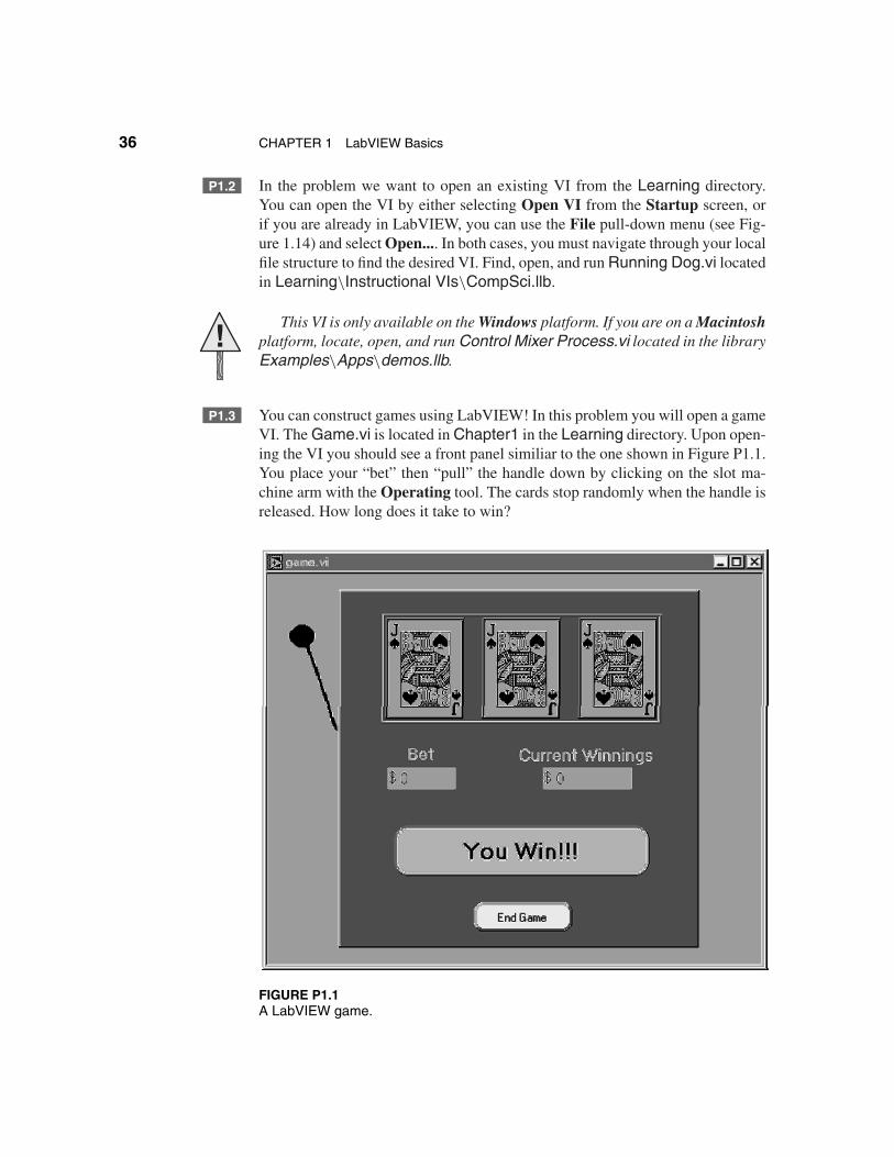
P1.3 You can construct games using LabVIEW! In this problem you will open a gameVI. The Game.vi is located in Chapter1 in the Learning directory. Upon open-ing the VI you should see a front panel similiar to the one shown in Figure P1.1.You place your “bet” then “pull” the handle down by clicking on the slot ma-chine arm with the Operating tool. The cards stop randomly when the handle isreleased. How long does it take to win?
FIGURE P1.1A LabVIEW game.