Embed Size (px)
Citation preview

instruNetLVLabVIEW™ Drivers for instruNet™
User’s Guide
Software Version 2.1Manual Version 2.1.2
8/11/02

Important Addendum• Determining the actual sample rate
The sample rate (Hz) returned by Config Timing may be incorrect.
Due to the behavior of the controller, the actual sample rate used duringdigitization may not be equal to the desired sample rate set using ConfigTiming or Set Sample Rate. Unfortunately, the controller does not set thesample rate until after digitization has been started. This means that thesample rate returned by Config Timing may not be correct! Byexperimentation, sample rates can be found where the desired samplerate will be the same as the actual sample rate.
It is important to call Get Sample Rate once after digitization has begun todetermine the actual sample rate.
The example VIs illustrate calling Get Sample Rate just after beginningdigitization, but before any loops are begun that handle servicing thebuffers. The sample rate returned can easily be passed into the loop forany real-time processing.
• LabVIEW 6i and front panel controlsOpening some VIs in LV6i yields an error.
LabVIEW 6i no longer supports coercing the values of a sub-VIs controlswhen they are passed from a calling VI. LabVIEW 6i also no longersupports suspending a VI when the value of a control is out of range.Some of the instruNetLV VIs have front panel controls set to coerce thevalue or suspend the VI if a control is out of range.
When these VIs are opened by LV6i, a warning will be given that thissetting is not supported. This is not an indication that the VI will not work. Ifthe values passed to the VI are out of range, the appropriate instruNeterror will be returned.

5
Table of Contents
Introduction.................................................................. 6Assumptions...............................................................................................................6System Requirements ..............................................................................................6About instruNetLV.......................................................................................................6Installation ...................................................................................................................6
Using instruNetLV........................................................ 8Initialization..................................................................................................................8Accessing instruNet Fields ......................................................................................8Configuring instruNet with the Probe Dialog ........................................................8Selecting Channels with the Probe Dialog ...........................................................8Saving and Recalling instruNet Configurations...................................................9Digitizing Waveforms.................................................................................................9Digitizing Multiple Channels.................................................................................. 10Outputting Waveforms............................................................................................ 10
instruNetLV VIs.......................................................... 11Channel Values....................................................................................................... 11Field Values.............................................................................................................. 12Digital......................................................................................................................... 14Digitizing.................................................................................................................... 15Timing........................................................................................................................ 18Trigger ....................................................................................................................... 21Configuration............................................................................................................ 22instruNet World........................................................................................................ 24Show Probe.............................................................................................................. 25Alerts.......................................................................................................................... 26Network Info.............................................................................................................. 27Advanced................................................................................................................... 30Core ........................................................................................................................... 31~subVIs ..................................................................................................................... 32
Appendix A: Useful Numbers..................................... 34
Appendix B: Binary File Format................................. 49

6
Introduction
AssumptionsThe following documentation assumes that the instruNet hardware, instruNet driverfiles and LabVIEW are installed and functioning. If necessary, please refer to therespective manuals for details. This documentation also assumes that you are familiarwith the operation and terminology of the computer (MacOS or Windows), instruNetWorld and LabVIEW. Again, please refer to the documentation that comes with thosepackages for any details.
System RequirementsinstruNetLV requires at least LabVIEW 4. Therefore, system requirements are the sameas LabVIEW. An additional 6MB of free disk space is required for the instruNetLV files.Using instruNetLV will require 500KB of RAM outside of the amount required by theLabVIEW VIs due to the requirements of the instruNet driver called by instruNetLV.instruNetLV supports both the NuBus and the PCI version of the instruNet controllercards.
About instruNetLVinstruNetLV is a collection of LabVIEW VIs that provide the LabVIEW programmer withan interface to GWI’s instruNet hardware. The advanced VIs allow direct access to theentire instruNet World and to the GWI driver that controls instruNet. These VIs areplatform specific LabVIEW calls to the iNetLV() routine in the source code that ships withinstruNet. Under the MacOS this consists of CINs that call the GWI Code Resource,while under Windows this consists of calls to the GWI DLL. Additional VIs for a platformare built from the appropriate advanced VIs and provide simplified access to specificfeatures of the instruNet hardware. These VIs replicate many of the routines foundthroughout the source code provided with instruNet.
InstallationThe instruNetLV collection of VIs ship as a self-extracting archive. Double-clicking on the.sea or .exe file will produce folders and VI libraries containing the collection. TheExamples library contains several examples to help illustrate the use of the instruNetLVVIs and may be placed anywhere you find convienent. The iNetLV 2 VIs folder containsthe VIs divided by function into a number of other folders or libraries. This folder is bestplaced in the user.lib folder to provide access to the VIs from the function menu.
By default, the MacOS version of the instruNetLV VIs use the PPC specificiNetLV(PPC).vi as their core subVI. To use the instruNetLV VIs on a 68K MacOScomputer replace this subVI call with the 68K specific iNetLV(68K).vi. The VIs haveidentical terminal arrangements, so no change in the wiring is necessary. LabVIEW willask you to save the changes to the instruNetLV VIs.

7
Since LabVIEW implements PPC CINs using the Shared Library Manager, theiNetLV(PPC).lsb file must be in the same location as the iNetLV(PPC).vi. Since 68KCINs are implemented using a Code Resource, the information within theiNetLV(68K).lsb can be saved within the iNetLV(68K).vi. The iNetLV(68K).lsb file doesnot have to be kept with the iNetLV(68K).vi, although this is recommended.

8
Using instruNetLV
Initialization (MacOS only)Under the MacOS, when the core iNetLV(XXX).vi is first loaded into memory byLabVIEW, an initialization procedure is performed. Any error during initialization is storedand returned when the core VI is first called by LabVIEW. If an error occurs duringinitialization, the core VI (and any other VIs that calls it) must be unloaded from memory,the error corrected, and then the VIs may be loaded back into memory for anotherattempt at initialization.
Accessing instruNet FieldsThe key to understanding instruNet and the instruNetLV VIs is to know which field withinthe instruNet World stores the desired information. Each aspect of the instruNethardware and driver has an associated field(s). Using instruNet is a matter of specifyingthe appropriate field and how you wish to access the field. The instruNet manualcontains descriptions of the fields and their functions. The instruNet manual andAppendix A of this manual contain listings of the useful numbers needed whenspecifying and accessing fields. The instruNetLV VIs simplify this process by alreadyspecifying the appropriate numbers for the desired action the VI is to perform. Most ofthe instruNetLV VIs function in a straightforward manner; calling upon instruNet toperform the action (e.g. returning a value) and then both instruNet and the VI stopactivity. Digitizing waveforms is a more complicated process that is discussed below.
Configuring instruNet with the Probe DialogThe Show Probe VIs are a convenient method for providing the user with the ability toconfigure aspects of instruNet. The dialog presented by these VIs provide a convenientpre-built user interface. When your LabVIEW program calls the Show Probe VI you canspecify which aspect of instruNet for which to present the configuration dialog. The userwill then have the chance to specify the settings that are desired and click a button to exitthe dialog. For example, to bring up the probe dialog appropriate for configuring all ofthe hardware settings of a channel (Sensor, Wiring, Range, etc.) call Show Probe(full)2.vi with the necessary network, device, module and channel and with settingGroup inequal to -3 (see SettingGroup Types in Appendix A). To bring up a dialog for configuringjust the input range for a channel call Show Probe(field) with the same above inputsplus fieldNum in equal to 5 (see HARDWARE Settings in Appendix A).
Selecting Channels with the Probe DialogWhen the user clicks one of the buttons, the Show Probe VIs return the currentlyaccessed settings, such as the network, device, module, channel, settingGroup out,and fieldNum out. This allows the Show Probe VIs to be used to give the user a simpleway to select a channel, field, etc. and return the choice to LabVIEW for further activity.

9
Saving and Recalling instruNet ConfigurationsTwo VIs allow the complete configuration of the instruNet World to be saved andrecalled. Get Network Settings(XXX).vi will return the complete settings of the instruNetWorld as an array and a scalar that can be saved to disk for later recall. Set NetworkSettings(XXX).vi can then be used later with this data to completely configure theinstruNet World based on the stored settings.
Digitizing WaveformsDigitizing waveforms requires that the instruNet driver be active in the background evenif no VI is currently running. This background activity begins when the instruNet StartRecord button is ‘pressed’ using Press Button 2.vi. The instruNet driver beginsdigitization in the background using whatever settings for digitizing (e.g. which channelsare enabled), timing (e.g. sample rate) and triggering (e.g. trigger mode) were specifiedbeforehand. In order for the background activity to succeed, the instruNet driver must becalled periodically to allow the servicing of the buffers used to store the incoming data.This is accomplished by calling Service All Buffers 2.vi several times a second within aloop for as long as digitization is happening. To access the data (even while digitizationis occurring) you call Access Buffer 2.vi once for each channel that has been enabled.This will return any new data in the channel’s buffer and does allow for the display ofdata without interrupting digitization. Digitization will stop once the specified number ofscans have occurred. Digitization can also be stopped at any time by using PressButton 2.vi to ‘press’ the instruNet Stop Record button. This should be done even ifdigitization has ended normally, since it ends the background activity of the instruNetdriver.
Digitize Channel Example.vi demonstrates the technique outlined above. The sequenceof steps is outlined below. All of these steps check for an error before they execute.1) Call Press Button 2.vi with Network Clear as the input. This tells instruNet to clearthe state of the network allowing the remaining VIs to configure the digitization with aclear state. This will disable digitization of all channels. This call takes several secondsand isn't necessary if you know the state of the network.2) Call Set Timing Values 2.vi to configure the timing values used by instruNet duringthe digitization. Needs to be done only once if you know they have been already defined.3) Call Set Trigger Values 2.vi to configure the trigger values used by instruNet duringthe digitization. Needs to be done only once if you know they have already been defined.4) Call Channel On-Off 2.vi to enable digitization of the desired channel of instruNet.Needs to be done only once if this has already been defined.5) Call Press Button 2.vi with Record Start as the input. This tells instruNet to begindigitization of the enabled channel. Digitization will use the trigger values and timingvalues specified in earlier steps.6) From within a loop call Service All Buffers 2.vi repeatedly to give instruNet thechance to service the digitization process. Check the values returned for the status ofthe digitization. Also from within the loop, call Access Buffer 2.vi to pull any new datafrom the channel’s buffer, display it on a chart and append it to an array with anyprevious data. This loop stops when the user presses the Front Panel’s Stop button, ifthere is an error reported, or once the digitization is complete.

10
7) Call Press Button 2.vi with Record Stop as the input to tell instruNet to stop thedigitization process.
Digitizing Multiple ChannelsAcquiring waveforms from multiple channels requires enabling multiple channels andhandling multiple buffers with repeated calls to Channel On-Off.vi and Access Buffer2.vi. If multiple networks are available this may also require additional calls to ServiceAll Buffers.vi. This process is simplified by using the three VIs designed to work with alist of channels (Enable List.vi, Access List.vi and Service List.vi). All of these VIs usean array to specify a list of input channels to process. Digitize List Example.vi illustratesthe use of these VIs to acquire multiple channesl. This example uses the same VIs asDigitize Channel Example.vi to configure the timing and triggering of the digitization.
Outputting WaveformsThe instruNetLV VIs can be used to output a waveform during digitization. The first stepis to enable digitization of an output channel (e.g. Vout 3) with Channel On-Off 2.vi. Oncethe channel has been enabled for digitization, the channels’ buffer needs to be filledwith the waveform to output. Load Buffer 2.vi accomplishes this step. Once the buffer isfilled with the waveform, the process of digitization will output the waveform. The samplerate, etc. of the output is determined by the same timing values used to acquire awaveform.
In-Out Example.vi illustrates the output of a waveform simultaneously with acquisitionby adding the output of a sine wave to Digitize Channel Example.vi.
Output of a waveform only requires that Service All Buffers 2.vi be called periodically.Access Buffer 2.vi is only required to acquire an input channel’s data.

11
instruNetLV 2.1 VIsThis section is an annotated list of the VIs grouped by function. Some of the VIs areidentical in function to VIs present in version 1 of instruNetLV but have modified inputsand outputs. These VIs have a Roman numeral two appended to the original VIsname (e.g. Get Field(SGL) 2.vi). Many of the controls and indicators are shared by theVIs and are only described the first time they are encountered.
Channel ValuesThese VIs read or write to the specified channel's valueEu field of the GENERALsettingGroup. The value is in engineering units and as a SGL.
Get Channel(SGL) 2.viReturns the value as a 32bit floating point (SGL).
address in Clusteraddress out ClusterA cluster that specifies an address within the instruNet World. The value of address in ispassed to address out to facilitate dataflow programming.
network U8NETWORK number {0...numNetworks}, 0 = Driver, 1 = 1st controller installed in thecomputer.
device U8DEVICE number {0...numDevices}, 0 = Controller, 1 = 1st device on network
module U8MODULE number within a hardware DEVICE {1...32}. Many devices have only 1module.
channel U8Hardware CHANNEL number {1...32}. Each device contains a number of channels,each of which has it's own channel number.
error in Clustererror out ClusterIf the value for status in the error in cluster is true than no action is taken and the error inpassed to error out. Otherwise, any error reported by the VI is passed to error out.
status BooleanTrue if an error has been reported.
code I32The error code generated by the call to the instruNet driver. See the instruNet manualor the listing in Appendix A for details.

12
source StringThe VI responsible for the error.
value read SGLThe value read from the channel in engineering units.
Set Channel(SGL) 2.viSets the value using a 32bit floating point (SGL).
value to write SGLThe value to write to the channel in engineering units.
Field ValuesThese VIs return the value of the specified field (the value read or string read indicators)in the representation indicated.
Get Field(I32) 2.viReturns the value as a signed 32bit integer (I32).
settings group or type I16If> 0, this is a settings group Number: {1...numSettingGroups}, which corresponds tothe order in which the settingGroup appears in the Setting popup menu (when using theinstruNet World application), with the first item in the menu is #1. If < 0, this is a settingsgroup Type. See the listing for settingGroup Types (sgt_VinHardware (-3) etc) inAppendix A for details.
field I16Field number within the settingGroup. The 1st field is #1, the next #2, etc. SeefgNums_... in Appendix A.
Get Field(SGL) 2.viReturns the value as a 32bit floating point (SGL).

13
Get Field(String) 2.viReturns the value as a LabVIEW string.
Get Field(U32) 2.viReturns the value as a unsigned 32bit integer (U32).
These VIs set the value of the specified field (the value to write or string to write controls)using the representation indicated.
Set Field(I32) 2.viSets the value using a signed 32bit integer (I32).
Set Field(SGL) 2.viSets the value using a 32bit floating point (SGL).
Set Field(String) 2.viSets the value using a LabVIEW string.

14
Set Field(U32) 2.viSets the value as a unsigned 32bit integer (U32).
DigitalThese VIs are useful for using the digital port.
Config Digital Directions.viConfigures the direction of each line of an 8-bit digital port.
direction bits U8Each bit sets the direction of a line of the specified digital port. Use 0 for an input lineand 1 for an output line. Line 1 of the port is specified by bit 1 (of 8) of directions bits.
Get Digital Line.viReturns the value of the specified line (1..8) of an 8-bit digital port. The address in needsto be a digital channel (e.g. Ch 25).
line U8Specifies which line (1..8) of the port.
state BooleanThe state of the line (true if high).
Get Digital Port.viReturns the value of the specifed channel’s ValueEU field as an unsigned byte. Usefulfor reading the value of a digital port (e.g. Ch 25).
Set Digital Line.viSets the value of a single line (1..8) of an 8-bit digital port. The channel needs to be adigital channel (e.g. Ch 25). The line also needs to be configured as an output line.

15
Set Digital Port.viSets the value of the specifed channel’s ValueEU field as an unsigned byte. Useful forwriting the value of a digital port (e.g. Ch 25).
DigitizingThese VIs are used to control the process of digitizing data. An example called DigitizeChannel Example.vi demonstrates how to use the instruNetLV VIs to acquire awaveform from a single channel. Digitize List Example.vi demonstrates how to acquirewaveforms from a list of channels. The DRIVER RAM buffer must be used, since theUSER RAM buffer is currently not supported by instruNetLV.
Access Buffer 2.viWhile digitizing, this VI pulls a segment of data out of the driver RAM buffer.
scan # U32The scan number of the scan that is currently being pulled from the buffer (base 1).
# pts U32The number of points pulled from the buffer. Equal to the size of the segment pulledarray.
segment start index U32The index of the first point returned in segment pulled relative to the start of the buffer(base 1 index).
segment pulled [SGL]The most recent segment of data pulled from the buffer in engineering units.
buffer address U32The location in memory of the first point in the buffer.
Channel On-Off 2.viEnables or disables digitizing for the specified channel by setting the DISPLAY field inthe DISPLAY settingGroup.
enable digitizing? Boolean

16
Set to true to enable digitizing of the specified channel, false to disable digitizing.
Channels Off 2.viDisables digitizing for all channels in the specified network. Makes sure that theDISPLAY field is off in the DISPLAY settingGroup and that the DIGITIZE field is off in theFILE, USERBUFFER, and DRIVERBUFFER settingGroups.
network in U8network out U8NETWORK number {0...numNetworks}, 0 = Driver, 1 = 1st controller installed in thecomputer.
Service All Buffers 2.viThis VI must be called continuously while digitizing to allow the processor to service allof the digitization buffers and to let LabVIEW monitor the status of the digitization.
network status ClusterContains the status information for the digitization.
Controller Is Finished BooleanReturns true if the controller has completed the digitization as specified by the timingvalues.
Last Scan # Pulled In Full U32The scan number of the last scan that was pulled in full from the buffer (base 1).
Last Scan # Pushed In Full U32The scan number of the last scan that was pushed in full to the buffer (base 1).
Next Access Ends Digitization BooleanTrue if the next segment of data pulled from the buffer will complete digitization.
Next Access Pulls to End of Scan BooleanReturns true if the next segment of data pulled from the buffer will complete the currentscan.
Save Option 2.viSpecifies how the data acquired by digitization should be saved; either off, to RAM, todisk, or user controlled.
Save Data I32(1) Off, data is not saved.(2) RAM, data is saved to a RAM buffer.

17
(3) Disk, data is streamed to a file on disk. The file must be specified in the appropriatefields.
(4) User, data is controlled in a user defined location. This is currently NOT supportedby instruNetLV.
Load Buffer 2.viThis VI loads the input SGL array into the buffer of the specified channel. The channelmust be an output channel (e.g. Vout 3). Additionally, the size of the input array mustmatch the size of the buffer. If not, Load Buffer will finish without loading the buffer andset sizes don’t match to true. Load Buffer returns the size of the buffer, so a secondattempt may be made after resizing the input array. The first attempt does no harm, so achannel’s buffer size can be determined by calling Load Buffer with an empty array. Thebuffer size will usually be the same as the value for Points Per Scan.
data to load SGL ArrayThe waveform data (in the channel’s engineering units) to load into the buffer.
sizes don’t match BooleanReturns true if the data array is not the same size as the buffer.
buffer size in points U32The buffer size in number of points, the actual size in bytes will be four times larger.
Enable List.viEnables digitization for the channels specified in address list in. Digitization for all otherchannels in the networks is disabled.
address list in [Cluster]address list out [Cluster]An array of address clusters (network, device, module and channel).
network list out [U8]An array containing all the networks within address list in.
Service List.viServices the buffers for each network in address list in.
network list [U8]An array containing all the networks within address list in.

18
status of networks [Cluster]An array of the network status cluster (see Service All Buffers 2.vi). The data for eachelement of the array is from the network specified in the corresponding element of thenetwork list array.
Access List.viAccess the buffers for each channel in the address list in.
info from buffers [Cluster]An array of clusters. Each cluster bundles the information for one buffer (see AccessBuffer 2.vi). Each element of the array contains the buffer information for thecorresponding element of the address list in.
Get Channel Direction 2.viReturns the direction of the specified channel; true if an input, false if an output.
Input Channel? Boolean
Get Digitizing State 2.viReturns true if the controller is digitizing.
Controller Digitizing? Boolean
TimingThese VIs return timing values used by the controller.
Get Ch % Sample Rate 2.viReturns % of the sample rate that will be used to digitize the specified channel.
% Sample Rate SGL
Get Min SecsPerTfr 2.viReturns the minimum seconds per transfer to and from the specified network.
Min Secs/Tfr SGL

19
Get Network BPS 2.viReturns the network data transfer rate in bits per second.
Network BPS I32
Get Number of Scans 2.viReturns the number of scans that will be digitized.
Number of Scans U32
Get Points Per Scan 2.viReturns the number of points that will be digitized per scan.
Points Per Scan U32
Get Sample Rate 2.viReturns the digitization sample rate in samples per second.
Sample Rate (Hz) SGL
Get Scan Mode 2.viReturns the digitization scan mode; Strip Chart, Oscilloscope Queued, or Oscilloscope.
Scan Mode I32(1) Strip Chart, continuous mode.(2) Oscilloscope, non-continuous mode with data pulled in a first in, last out manner.(3) Oscilloscope Queued, non-continuous mode with data pulled in a first in, first out
manner.
Get Switching Mode 2.viReturns the channel switching mode used during digitization; Accurate or Fast.
Ch Switch Mode I32(1) Accurate, yet slower.(2) Fast, yet less accurate.

20
These VIs set timing values used by the controller.
Set Ch % Sample Rate 2.viSets the % of the sample rate used to digitize the specified channel.
Set Min SecsPerTfr 2.viSets the minimum seconds per transfer to and from the specified network.
Set Network BPS 2.viSets the network data transfer rate in bits per second.
Set Number of Scans 2.viSets the number of scans to digitize.
Set Points Per Scan 2.viSets the number of points to digitize per scan.
Set Sample Rate 2.viSets the digitization sample rate in samples per second.
Set Scan Mode 2.viSets the digitization scan mode; Strip Chart, Oscilloscope Queued, or Oscilloscope.

21
Set Switching Mode 2.viSets the channel switching mode used during digitization; Accurate or Fast.
Set Timing Values 2.viSets the timing values used by the controller during digitization.
sampling ClusterInput cluster that bundles controls for Sample Rate (Hz), Points Per Scans and Numberof Scans.
Show Overflow Alert BooleanSet to true if you want instruNetLV to generate an alert dialog upon an overflow.
actual sample rate (Hz)Returns the actual sample rate the network will use during digitization. May not be thesame as the requested sample rate.
TriggerThese VIs configure the triggering used during digitization.
Set Trigger Mode 2.viSets the trigger mode for digitization; Off, Automatic, or Normal.
Trigger Mode I32(1) Off, (2) Auto, (3) Normal.
Set Trigger Slope 2.viSets the trigger slope for digitization; Rising or Falling.
Trigger Slope I32(1) Rising, (2) Falling.

22
Set Trigger Source 2.viSets the network address (network, device, module and channel) of the trigger sourcefor digitization.
Trigger Source ClusterInput cluster that bundles controls for specifying the network, device, module andchannel of the trigger source.
Set Trigger Threshold 2.viSets the trigger threshold in engineering units.
Trigger Threshold SGL
Set Trigger Values 2.viSets the trigger values used during digitization.
ConfigurationThese VIs configure different portions of the instruNet World.
Config Timing.viConfigures the Timing Settings used by the network. This VI is an alternative to SetTiming Values 2.vi and uses a single cluster for the major timing values.
Timing Settings ClusterA cluster containing the major timing values (see the Timing VIs)
pts/scan U32Same as Points Per Scan.
# of scans U32Same as Number of Scans.
Scan Mode I32

23
Sample Rate SGLSame as Sample Rate (Hz).
Switching I32Same as Ch Switch Mode.
Config Trigger.viConfigures the Trigger Settings used by the network. This VI is an alternative to the SetTrigger Values 2.vi and uses a single cluster for the trigger values.
Trigger Settings ClusterA cluster containing the trigger settings (see the Trigger VIs).
Trigger I32Same as Trigger Mode.
Threshold SGLSame as Trigger Threshold.
Slope I32Same as Trigger Slope.
Source ClusterSame as Trigger Source.
Config Timer.viConfigures one of the digital timers located on the controller card.
Timer U8Specifies which timer to configure (from 1 to 10).
Timer Settings ClusterA cluster containing the timer settings.
Function U32Species which timer function to use.(1) Digital In, (2) Digital Out, (3) Clock Output, (4) Period Measurement
Clock Period SGLSpecifies the period (if the timer function is Clock Output).
Clock Out Hi SGLSpecifies the duty cycle (if the timer function is Clock Output).

24
Measure U32Specifies the measurement mode (if the function is Period Measurement).(1) Cycle Time, (2) High Time
Measure Resolution U32Specifies the measurement resolution (if the function is Period Measurement).(1) 0.25 microseconds, (2) 4 milliseconds
Measure Cycles SGLSpecifies the number of cycles measured (if the function is Period Measurement).
Config Vin Channel.viConfigures the hardware settings for the specified input channel.
Hardware Settings ClusterSensor U16Specifies the sensor that is connected to the channel (e.g. (1) Voltage). See the frontpanel, instruNet Manual or Appendix A for values.
Wiring U16Specifies the wiring used to connect the sensor (e.g. (1) Vin-Gnd). See the front panel,instruNet Manual or Appendix A for values.
Low Pass U16Specifies the low pass filter to use during digitization.(1) Off, (2) 40Hz, (3) 4000Hz
Integrate SGLSpecifies the integration time used during digitization.
Range U16Specifies the range for the channel.(1) +-5V, (2) +- 0.6V, (3) 80 mV, (4) 10mV
instruNet WorldThese VIs operate on the instruNet World window.
Open instruNet 2.viOpens the instruNet World window to the specified page. Program control is owned bythe driver (i.e. NOT LabVIEW) until the user quits or closes instruNet World.
Page to Open I32

25
(1) Record page(2) Network page(3) Test page
Press Button 2.viPresses the specified button within the instruNet World window. The window does NOTneed to be open in order for the action to take place.
Button to Press I32Please see the listing of Button Press Commands in Appendix A for the values thatcorrespond to each button.
Get Network Settings(XXX).viReturns an array containing the all the settings in the instruNet World. This array can besaved to disk to be recalled and reconfigure the instruNet World.
settings array [I16]An array containing the settings within the instruNet World.
bytes of data U32The number of bytes of the settings array that contain actual data.
Set Network Settings(XXX).viConfigures the instruNet World using the settings from the settings array. The only wayto get a valid settings array is from a previous call to Get Network Settings(XXX).vi.
Show ProbeThese VIs show the probe dialog. The initial address accessed is specified by addressin. On return, the address out cluster contains the currently accessed network address.
Show Probe(channel) 2.viShows the probe dialog with the channel address only ([net/dev/mod/chan] popups).
Cancelled? BooleanTrue if the user pressed Cancel to exit the dialog.

26
Show Probe(field) 2.viShows the probe dialog with the field address only ([net/dev/mod/chan/set/field]popups).
settingGroup in I16The initial settingGroup displayed by the dialog.
fieldNum in I16The initial field displayed by the dialog.
settingGroup out I16fieldNum out I16The settingGroup and field displayed when the user exits the dialog.
Show Probe(full) 2.viShows the full probe dialog.
AlertsThese VIs are used to control how the instruNet driver displays alerts.
Get Show Alert 2.viReturns whether the instruNet driver is configured to show an alert dialog upon an error.
Show Alert Is BooleanReturns true if instruNetLV will display an alert dialog upon an error.
Set Show Alert 2.viConfigures the instruNet driver to either show or not show an alert dialog upon an error.Returns the setting that was in place BEFORE the VI was called.
Set Show Alert BooleanSet to true if you want instruNetLV to show an alert dialog upon an error.
Show Alert Was BooleanReturns true if the alert dialog was set to be displayed prior to calling the VI

27
Set Overflow Alert 2.viConfigures the instruNet driver to either show or not show an alert dialog upon a bufferoverflow during digitization.
Show Overflow Alert BooleanSet to true if you want instruNetLV to generate an alert dialog upon an overflow.
Network InfoA set of VIs that return useful information about the instruNet World.
Get Field Info.viReturns information about the specified field within the instruNet World.
fieldNum I16Field number within the settingGroup. The 1st field is #1, the next #2, etc. SeefgNums_... in Appendix A.
settingGroupNumOrType I16If> 0, this is a settings group Number: {1...numSettingGroups}, which corresponds tothe order in which the settingGroup appears in the Setting popup menu (when using theinstruNet World application), with the first item in the menu is #1. If < 0, this is a settingsgroup Type. See the listing for settingGroup Types (sgt_VinHardware (-3) etc) inAppendix A for details.
netNum U8NETWORK number {0...numNetworks}, 0 = Driver, 1 = 1st controller installed in thecomputer.
deviceNum U8DEVICE number {0...numDevices}, 0 = Controller, 1 = 1st device on network
moduleNum U8MODULE number within a hardware DEVICE {1...32}.
chanNum U8Hardware CHANNEL number {1...32}. Each device contains a number of channels,each of which has it's own channel number.

28
Error I16Returns the error code generated by the call to the instruNet driver. See the instruNetmanual or the listing in Appendix A for details.
Field Info ClusterOutput cluster containing the following indicators providing information about thespecified field.
type I32The type of user interface appropriate for the field.
category I32The category of user interface for the field.
representation I32The native representation of the value in the field. See Data Types in Appendix A for alisting.
read/write BooleanReturns true if the field is read/write, false if the field is read only.
Names [String]Contains the names of the network, device, module, channel, settingGroup and field.
PopUp Items [String]Contains a list of the items in the PopUp menu associated with the field’s settingGroup.
# PopUp Items I32The number of items in the associated settingGroup’s PopUp menu.
Get Seconds Since Reset.viReturns the number of seconds since the network has been reset.
Seconds SGL
These VIs return true if the item exists within the specified portion of the instruNet World.All of the <X> Exists? terminals are Boolean indicators.
Does Channel Exist.vi
Does Device Exist.vi

29
Does Field Exist.vi
Does Module Exist.vi
Does Network Exist.vi
Does Setting Exist.vi
These VIs return how many of the items exist within the specified portion of the instruNetWorld. All of the # of <X> terminals are I32 indicators.
Number of Channels.vi
Number of Devices.vi
Number of Fields.vi
Number of Modules.vi
Number of Networks.vi

30
Number of Settings.vi
AdvancedThese VIs call the instruNet driver to read or write any field in the instruNet World usinga value in the indicated representation. The value of intention determines the actiontaken. For almost all purposes the previous VIs will provide easier access to theinstruNet hardware.
iNetLV_I32.viUses a signed 32bit integer (I32).
intention I16Tells the instruNet driver what to do when accessing the field. Please see the listing ofField Access Intentions in Appendix A for details.
Parameters ClusterA cluster of values used mainly for internal purposes. Some of the elements in thecluster (A, B etc.) are used by certain calls to instruNet to return additional informationand will be mentioned in the documentation.
I32 to write I32The value to write to the specified field within the instruNet World.
I32 read I32The value read from the specified field within the instruNet World.
iNetLV_SGL.viUses a 32bit floating point (SGL).
SGL to write SGLThe value to write to the specified field within the instruNet World.

31
SGL read SGLThe value read from the specified field within the instruNet World.
iNetLV_String.viUses a LabVIEW string.
String to write StringThe value to write to the specified field within the instruNet World.
String read StringThe value read from the specified field within the instruNet World.
iNetLV_U32.viUses an unsigned 32bit integer (U32).
U32 to write U32The value to write to the specified field within the instruNet World.
U32 read U32The value read from the specified field within the instruNet World.
Core MacOS onlyThe CIN based VIs used by the MacOS version of instruNetLV. Each VI is platformspecific and allows LV to directly access the fields within the instruNet World.
iNetLV(68K).viThe CIN based VI for 680x0 based Macs.

32
argTypeIn U8Specifies the representation of the value being read or written. See the listing of DataTypes in Appendix A for details.
typeCastArgIn StringContains the value that is to be written to the instruNet field. MUST be TypeCast to astring using the TypeCast Function since the VI is not polymorphic.
ptrToArgOut U32Returns the location in memory that contains the value returned by the call to theinstruNet driver. How the location needs to be accessed is determined by the value ofargTypeIn.
iNetLV(PPC).viThe CIN based VI for PPC based Macs.
~subVIsSome utility VIs used by other VIs in the instruNetLV collection. Most of these involvememory access and manipulation and should NOT be used for other purposes.
addresses2networks.viConverts an array of address clusters to an array containing all the networks specifiedby the addresses.
CStr15[] Address To String[].viReads the information at the memory address specified and converts it from a CStr15[]to a LabVIEW String[].
CStr255 Address To String.viReads the information at the memory address specified and converts it from a CStr255to a LabVIEW String.
iNetLV_Error.vi Win95 onlyReturns the error reported by the last call to the instruNet Driver.
iNetLV_Params.vi Win95 onlyReturns the Parameter structure associated with the last call to the instruNet Driver.Most of the values are for internal use only.

33
iNet_Peek_int16.vi Win95 onlyReturns the value at the specified memory address as a I16.
iNet_Peek_int32.vi Win95 onlyReturns the value at the specified memory address as an I32.
iNet_Peek_flt32.vi Win95 onlyReturns the value at the specified memory address as a SGL.
iNet_Poke_flt32.vi Win95 onlySets the value at the specified memory address using a SGL.
The following VIs are used for memory manipulation by the Mac version of theinstruNetLV VIs. They must NOT be used for other purposes. Each VI has a version for68K and for PPC Macs. They are all CIN based and have corresponding .lsb files thatshould stay in the same folder as the VI.
Array to Handle(XXX).vi MacOS only
Handle to Array(XXX).vi MacOS only
Dispose of Handle(XXX).vi MacOS only

34
Appendix A: Useful NumbersThe following lists provide useful values for the various controls and indicators of theinstruNetLV VIs. The information is adapted from the header files that come as part ofthe source code provided by GWI with the instruNet hardware. Several chapters at theback of the instruNet Manual also have listings of many of these numbers.
SettingGroup types (i.e. values for settingGroupNumOrType)settingGroup (i.e. "Settings") types (settingGroupType's must be negative)
BADsgt_noneFound = -1 nothing foundsgt_UnRecognizedType = -2 unrecognized (user probably needs a newer driver that works with
this hardware ??)
MODEL 100 LIKE HARDWARE DEVICEsgt_VinHardware = -3 Vin "Hardware" settingGroupType {sensorType, a/d range,
analog lp, function}sgt_VinConstants = -4 Vin "Constants" settingGroupType
{Ro,Rshunt,Vexcit,GF,alpha,delta}sgt_Mod100DinDout = -5 8bit Mod 100 Digital I/O settingGroup = {din, dout, direction}
sgt_General = -6 GENERAL settingGroupType struct {valueEU, chanName,unitsLabel, userName...}
sgt_Display = -7 DISPLAY settingGroup = {dispOnOff, dispMaxEU,dispMinEU}
FILTERsgt_LowPass = -8 LOW PASS filter settingGroup typesgt_HighPass = -9 HIGH PASS filter settingGroup typesgt_BandPass = -10 BAND PASS filter settingGroup typesgt_BandStop = -11 BAND STOP filter settingGroup type
DIGITIZER channel in CONTROLLER device.sgt_Timing = -12 {DigitizeOnOff, PtsPerScan, NoOfScans, ScanMode,
SampleRate}sgt_Trigger = -13 {TriggerMode, ThresholdEu, Slope, PreTrigSec, SrcNet,
SrcModule, SrcDevice, SrcChannel}
CONTROLLER timer channelsgt_Timer = -14 TIMER settingGroup = {functionPop, clkTotalSecs, clkHiSecs,
measHiOrCyclePop, measResolution, measNumPeriods}
BUFFERSsgt_DriverRamBuffer = -15 Driver Ram Buffer = {DigitizeOnOff, ScanNumIn, PtNumIn..}sgt_UserRamBuffer = -16 User Ram Buffer = {DigitizeOnOff, userBufferAddr, ptrSize,
ScanNumIn, PtNumIn..}sgt_File = -17 File = {FileName, Command, ScanNumIn, PtNumIn,
ScanNumIn ..}
DRIVERsgt_RecordOptions = -18 RECORD OPTIONS settingGroup = {}sgt_MasterDirectory = -19 MASTER DIRECTORY settingGroup = {pathname, command,
save/load settings}

35
Field Access Intentions (i.e. values for intention ) thing that you want to do when you call iNet
intention_getValue = 1 get the value of the fieldintention_setValue = 2 set the value of the fieldintention_getNameStr = 3 get name of field (i.e. string)intention_getMaxValue = 4 get maximum value of the fieldintention_getMinValue = 5 get minimum value of the fieldintention_getUserInterfaceType = 6 get user interface type {e.g. }intention_getDefaultValue = 7 get the defaultValue of the fieldintention_nativeStorageType = 8 get the native storageType of the field {e.g. iNetDT_FLT32,
iNetDT_INT16, iNetDT_P_Str15}intention_getValueAndPullData = 9 get the value of the field (USER RAM BUFFER userBufferAddr
field or DRIVER RAM BUFFER bufferPtr field) and also pulldata out of the buffer and place 'pointToPullindex' into A,'numPointsToPull' into B, and 'scanNumIn' into C. gsw11/25/95
ADMINISTRATIVEintention_doNothing = 4000 do nothing (just process iNet_Request struct) (all we do is check
the network address and and then calc the Global struct ptrs)intention_DisableAllChannelDigitizing = 4005 Disable channel digitizing for all channels in this network. This
will make sure that the "Display" field in the DISPLAYSettingGroups is OFF, and that the "Digitize" field is OFF inthe FILE, USERBUFFER, and DRIVERBUFFERSettingGroups.
SHOW ALERT UPON ERROR CONTROLintention_ShowAlertOnError = 8000 tells driver to show an alert upon error (this is the default) returns
1 if driver WAS set up to show an alert upon error; 0 otherwiseintention_NoShowAlertOnError = 8001 tells driver to NOT show an alert upon error returns 1 if driver
WAS set up to show an alert upon error; 0 otherwiseintention_GetShowAlertOnErrorStatus = 8002 returns 1 if driver WAS set up to show an alert upon error; 0
otherwise
DETERMINE IF NETWORK ELEMENT EXISTSintention_ThisExists_Network = 8003 Returns 1 if NETWORK = {netNum} exists; FALSE (0)
otherwise.intention_ThisExists_Device = 8004 Returns 1 if DEVICE = {netNum, deviceNum} exists; FALSE
(0) otherwise.intention_ThisExists_Module = 8005 Returns 1 if MODULE = {netNum, deviceNum, moduleNum}
exists; FALSE (0) otherwise.intention_ThisExists_Channel = 8006 Returns 1 if CHANNEL = {netNum, deviceNum, moduleNum,
channelNum} exists; FALSE (0) otherwise.intention_ThisExists_Setting = 8007 Returns 1 if SETTING = {netNum, deviceNum, moduleNum,
channelNum, settingNum} exists; FALSE (0) otherwise.intention_ThisExists_Field = 8008 Returns 1 if FIELD = {netNum, deviceNum, moduleNum,
channelNum, settingNum, fieldNum} exists; FALSE (0)otherwise.
INTERROGATE NETWORKintention_GetNumNetworks = 8009 Returns the # of instruNet Networks.intention_GetNumDevices = 8010 Returns the # of Devices in the specified Network.intention_GetNumModules = 8011 Returns the # of Modules in the specified {Network, Device}.

36
intention_GetNumChannels = 8012 Returns the # of Channels in the specified {Network, Device,Module}.
intention_GetNumSettings = 8013 Returns the # of Settings in the specified {Network, Device,Module, Channel}.
intention_GetNumFields = 8014 Returns the # of Fields in the specified {Network, Device,Module, Channel, SettingGroup}.
USER INTERFACEintention_Get_UI_Catagory = 8017 Returns the user interface catagory (i.e. itemType_iNet enum in
header file; e.g. ion_StaticText (3), ion_EditText (4),ion_UserItem (popup) (5)).
intention_Get_NumPopupItems = 8018 Returns the number of items in a popup, if the field userinterface is a popup. (e.g. returns 2 if the popup shows {"ON","Off"}).
intention_Get_PopupStringArray = 8019 Returns the pointer to an array of C Str15 strings that contain theitems in the popup (i.e. iNetStr15 popupItems[]).
intention_Get_AddrNamesStringArray = 8020 Returns the pointer to an array of C Str15 strings that contain thenames of the Network, Device, Module, Channel, Settings, Field(i.e. iNetStr15 array[0] = Network Name, array[1] = DeviceName, array[2] = Module Name, array[3] = Channel Name,array[4] = Settings Name, array[5] = Field Name).
intention_GetChannelDirection = 8021 Returns the direction of the channel: 0 is input (e.g. a/d), and 1is output (e.g. d/a). 5/1/96
GET/SET NETWORK STATEintention_getHandleToNetworkState = 8022 Returns a Handle to the Network State (in uint32). The Caller
must dispose of it after using it (e.g. DisposHandle() onMacintosh, GlobalFree() on Windows). To get the Handle size,call GetHandleSize() on Macintosh, sssssss on Windows) gsw11/25/95
intention_setNetworkStateWithHandle = 8023 Sets the network state with the passed Handle. The Caller mustdispose after calling this routine. The handle must haveoriginated from a GET_HANDLE_TO_NETWORK_STATE()call that was done previously. gsw 11/25/95
intention_disposeOfNetworkState = 8024 Dispose of all instruNet network state. This will cause the thenext call to the instruNet driver to implement the POWER ONboot process. Call CloseDriverAndReleaseDriverRam() to releaseram held by the driver itself. gsw 9/8/96
SERVICE THE DIGITIZATON PROCESSintention_serviceAllDigitizeBuffers = 8028 Services buffers during the digitization process if they are
holding new data (otherwise this does nothing). This must bedone continuously while digitizing. Returns TRUE (1) if thenext data pulled out out of the buffers is that last pull; FALSE(0) otherwise. A_PARAM() is set to TRUE (1) if we pulled tothe end of a Scan; FALSE (0) otherwise. B_PARAM() is set tothe last scan # (base 1) that was pulled in full. C_PARAM() isset to the last scan # (base 1) that was pushed in full.
SHOW PROBE DIALOGintention_showProbeDialog_Full = 8031 Shows the full probe dialog. On return,
netNum_PARAM(gRequestP),deviceNum_PARAM(gRequestP), etc contain the accessedaddress.
intention_showProbeDialog_ChannelAddrOnly = 8032

37
Shows the probe dialog with the channel address only([net/dev/mod/chan] popups). On return,netNum_PARAM(gRequestP),deviceNum_PARAM(gRequestP), etc contain the accessedaddress. A_PARAM(gRequestP) is set to 1 if the user pressedCANCEL, 0 if the user pressed OK to exit the dialog.
intention_showProbeDialog_FieldAddrOnly = 8033Shows the probe dialog with the field address only([net/dev/mod/chan/set/Field] popups). On return,netNum_PARAM(gRequestP),deviceNum_PARAM(gRequestP), etc contain the accessedaddress. A_PARAM(gRequestP) is set to 1 if the user pressedCANCEL, 0 if the user pressed OK to exit the dialog.
MANAGEMENTintention_Set_gClickOnThisWindowToQuitiNet = 8040
Setting a WindowPtr_ such that if this window is clicked onwhile the instruNet World Window is opened, then the instruNetWorld Window will QUIT (e.g. the host application window).gsw 3/3/96
Data Types (i.e. values for argTypeIn ) types of data stored in the instruNet fields (this must fit into an UINT8 = {0...255})
iNetDT_INT16 = 0 16bit integer, signediNetDT_INT16bus = 1 16bit integer, signed; yet data is on a card andiNetDT_UINT16 = 2 16bit integer, unsigned must be transferred to with 16bit
transfers.iNetDT_INT32 = 3 32bit integer, signediNetDT_UINT32 = 4 32bit integer, unsignediNetDT_FLT32 = 5 32bit float (ieee Macintosh format)iNetDT_Double = 6 'double', as determined by the compiler (e.g. flt64, flt80, flt96,
flt128)iNetDT_INT16comp = 7 16bit integer, signed; yet compressed in the standard iNet
'iNetDT_INT16comp" manner.iNetDT_P_Str15 = 8 PASCAL Str15 string (15 chars, 0th char is length)iNetDT_P_Str255 = 9 PASCAL Str255 string (255 chars, 0th char is length)iNetDT_C_Str15 = 10 C Str15 string (15 chars, 0x00 terminate)iNetDT_C_Str255 = 11 C Str255 string (255 chars, 0x00 terminate)
iNetDT_READ_ONLY_BIT = 128 this is ADDED to the iNetDataType value if the field is readonly.
iNetError error codes (i.e. values for Error ) iNet error codes
iNetErr_None = 0 no erroriNetErr_General = 1 general erroriNetErr_ControllerNotInitialized=2 InitializeDriverAndControllers_iNet() has not been callediNetErr_InitializationFailed = 3 InitializeDriverAndControllers_iNet was called, yet failediNetErr_DeviceNumOutOfRange = 4 Device number is out of range (is it connected & powered on?)iNetErr_ChannelNumOutOfRange = 5 Channel number is out of rangeiNetErr_FieldNumOutOfRange = 6 Field number is out of rangeiNetErr_ControllerNotFound = 7 iNet Controller not found

38
iNetErr_FieldDoesNotExist = 8 (deviceNum, chanNum, fieldNum) refer to field that does notexist
iNetErr_BadfieldNativeDataType = 9 bad iNetFieldDataType valueiNetErr_BadFieldReadType = 10 bad iNetFieldReadType valueiNetErr_TimeoutAtReadBegin = 11 time out at read beginiNetErr_TimeoutAtWaitForReadDone = 12 timeout at wait for read doneiNetErr_ControllerIsInWeeds = 13 controller is in the weedsiNetErr_illegalDataType = 14 illegal data typeiNetErr_FailedCopyDataTest = 15 failed the CopyWaveData() testiNetErr_CompressorHitError = 16 compressor hit erroriNetErr_FailedRamTest = 17 failed board ram testiNetErr_RanOutOfMemory = 18 ran out of memoryiNetErr_AlertFailed = 19 the routine that shows an alert failediNetErr_CtrlrRomNotBooting = 20 iNet Controller's ROM does not seem to boot up (poss
problem: controller, bus, rom)iNetErr_CtrlrRamNotBooting = 21 iNet Controller's driver in RAM does not seem to boot up (poss
problem: controller, bus, ram, rom, download from ucontroller,bad driver downloaded from host)
iNetErr_DriverDownloadFailed = 22 the download of the uController driver into controller ram failed(driver may be bad, or hardware is bad) (the keys and copyrightdid not match up).
iNetErr_CtrlrRWTestFailed = 23 failed during controller r/w test in Test_DualPort_Ram()iNetErr_InterfaceBlockTestFailed = 24 Interface block between uController and host computer is invalidiNetErr_IncCounterTestFailed = 25 Controller failed CounterInc testiNetErr_EchoCmdToStatusTestFailed = 26 Controller failed EchoCmdToStatus testiNetErr_ControllerBootTestFailed = 27 Controller failed Test_A_Booted_Controller testiNetErr_ControlleFailedToBoot = 28 Controller failed to Boot.iNetErr_ControllerCmdFailed = 29 Controller failed to execute command
GUI Errors.iNetErr_GUI = 30 error related to graphical user interface
iNet Bus error codesiNetErr_QSPI_Busy = 31 iNet Bus is busy runningiNetErr_QSPI_Halted = 32 iNet Bus hit HALT erroriNetErr_QSPI_ArgOutOfRange = 33 iNet Bus argument out of rangeiNetErr_QSPI_TimeOutErr = 34 iNet Bus hit time out erroriNetErr_FlakyNetwork = 35 iNet Bus is acting flaky (need terminator?)
Driver ErrorsiNetErr_CouldNotLocateDriverFile = 36 could not find the DRIVER code resource file.iNetErr_netNumOutOfRange = 37 netNum is out of rangeiNetErr_SettingGroupNumOutOfRange = 38 settingGroupNum is out of rangeiNetErr_UnitTypeOutOfRange = 39 deviceType is out of rangeiNetErr_DriverDidNotSetErrCode =40 Driver did not get a chance to set the error code; therefore
Driver is in trouble.iNetErr_SettingGroupTypeOutOfRange = 41 settingGroupType is out of range
Etc CodesiNetErr_ModuleNumOutOfRange = 42 Module number is out of range gsw 5/2/95iNetErr_IntentionNumOutOfRange =43 Intention number is out of range gsw 5/2/95iNetErr_ReadOnlyField = 44 Cannot write to this field, read only gsw 5/2/95iNetErr_WriteOnlyField = 45 Cannot read from this field, write only gsw 5/2/95iNetErr_FieldValueOutOfRange = 46 Tried to set a field with a value that is too high or low gsw
5/2/95
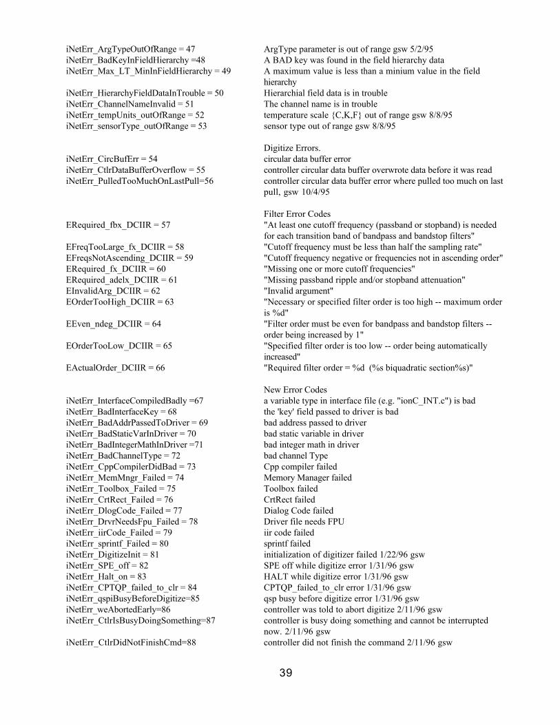
39
iNetErr_ArgTypeOutOfRange = 47 ArgType parameter is out of range gsw 5/2/95iNetErr_BadKeyInFieldHierarchy =48 A BAD key was found in the field hierarchy dataiNetErr_Max_LT_MinInFieldHierarchy = 49 A maximum value is less than a minium value in the field
hierarchyiNetErr_HierarchyFieldDataInTrouble = 50 Hierarchial field data is in troubleiNetErr_ChannelNameInvalid = 51 The channel name is in troubleiNetErr_tempUnits_outOfRange = 52 temperature scale {C,K,F} out of range gsw 8/8/95iNetErr_sensorType_outOfRange = 53 sensor type out of range gsw 8/8/95
Digitize Errors.iNetErr_CircBufErr = 54 circular data buffer erroriNetErr_CtlrDataBufferOverflow = 55 controller circular data buffer overwrote data before it was readiNetErr_PulledTooMuchOnLastPull=56 controller circular data buffer error where pulled too much on last
pull, gsw 10/4/95
Filter Error CodesERequired_fbx_DCIIR = 57 "At least one cutoff frequency (passband or stopband) is needed
for each transition band of bandpass and bandstop filters"EFreqTooLarge_fx_DCIIR = 58 "Cutoff frequency must be less than half the sampling rate"EFreqsNotAscending_DCIIR = 59 "Cutoff frequency negative or frequencies not in ascending order"ERequired_fx_DCIIR = 60 "Missing one or more cutoff frequencies"ERequired_adelx_DCIIR = 61 "Missing passband ripple and/or stopband attenuation"EInvalidArg_DCIIR = 62 "Invalid argument"EOrderTooHigh_DCIIR = 63 "Necessary or specified filter order is too high -- maximum order
is %d"EEven_ndeg_DCIIR = 64 "Filter order must be even for bandpass and bandstop filters --
order being increased by 1"EOrderTooLow_DCIIR = 65 "Specified filter order is too low -- order being automatically
increased"EActualOrder_DCIIR = 66 "Required filter order = %d (%s biquadratic section%s)"
New Error CodesiNetErr_InterfaceCompiledBadly =67 a variable type in interface file (e.g. "ionC_INT.c") is badiNetErr_BadInterfaceKey = 68 the 'key' field passed to driver is badiNetErr_BadAddrPassedToDriver = 69 bad address passed to driveriNetErr_BadStaticVarInDriver = 70 bad static variable in driveriNetErr_BadIntegerMathInDriver =71 bad integer math in driveriNetErr_BadChannelType = 72 bad channel TypeiNetErr_CppCompilerDidBad = 73 Cpp compiler failediNetErr_MemMngr_Failed = 74 Memory Manager failediNetErr_Toolbox_Failed = 75 Toolbox failediNetErr_CrtRect_Failed = 76 CrtRect failediNetErr_DlogCode_Failed = 77 Dialog Code failediNetErr_DrvrNeedsFpu_Failed = 78 Driver file needs FPUiNetErr_iirCode_Failed = 79 iir code failediNetErr_sprintf_Failed = 80 sprintf failediNetErr_DigitizeInit = 81 initialization of digitizer failed 1/22/96 gswiNetErr_SPE_off = 82 SPE off while digitize error 1/31/96 gswiNetErr_Halt_on = 83 HALT while digitize error 1/31/96 gswiNetErr_CPTQP_failed_to_clr = 84 CPTQP_failed_to_clr error 1/31/96 gswiNetErr_qspiBusyBeforeDigitize=85 qsp busy before digitize error 1/31/96 gswiNetErr_weAbortedEarly=86 controller was told to abort digitize 2/11/96 gswiNetErr_CtlrIsBusyDoingSomething=87 controller is busy doing something and cannot be interrupted
now. 2/11/96 gswiNetErr_CtlrDidNotFinishCmd=88 controller did not finish the command 2/11/96 gsw

40
iNetErr_CodeGenSegmentErr=89 code generation segment error 2/22/96 gswiNetErr_CPTQP_is_Bad=90 CPTQP is bad 6/01/96 gswiNetErr_CompilerErr=91 Compiler error 6/18/96 gswiNetErr_DrvrOrUserBufferOverflow = 92 User or Driver data buffer overwrote data before it was read
8/18/96 gswiNetErr_NonCompatible_OS = 93 Operating System (version) is not compatible with driver
8/28/96 gsw
STATUS register error codes.iNetErr_StatusRegBase = 10000 this is an error code from the iNet stats register that is
(10000+status)iNetErr_StatusRegEnd = 10255 last status register location
Open Window Commands (i.e. values for Page to Open ) These are field values for the OpenWindow Channel within the DRIVER.
iNetCM_OpenWindow_Record = 1 open the RECORD pageiNetCM_OpenWindow_Network = 2 open the NETWORK pageiNetCM_OpenWindow_Test = 3 open the TEST page
Button Press Commands (i.e. values for Button to Press ) These are field values for commands that press buttons in the instruNet World window.
RECORD pageiNetCM_BtnPress_Record_Start = 1 press 'Start' button in RECORD pageiNetCM_BtnPress_Record_Stop = 2 press 'Stop' button in RECORD pageiNetCM_BtnPress_Record_Open = 3 press 'Open' button in RECORD pageiNetCM_BtnPress_Record_Save = 4 press 'Save' button in RECORD pageiNetCM_BtnPress_Record_Options = 5 press 'Options' button in RECORD pageiNetCM_BtnPress_Record_Timing = 6 press 'Timing' button in RECORD pageiNetCM_BtnPress_Record_Trigger = 7 press 'Trigger' button in RECORD pageiNetCM_BtnPress_Record_Probe = 8 press 'Probe' button in RECORD page
PROBE page
NETWORK pageiNetCM_BtnPress_Network_Restore=9 press 'Restore' button in NETWORK pageiNetCM_BtnPress_Network_Store = 10 press 'Store' button in NETWORK pageiNetCM_BtnPress_Network_Open = 11 press 'Open' button in NETWORK pageiNetCM_BtnPress_Network_Save = 12 press 'Start' button in NETWORK pageiNetCM_BtnPress_Network_Clear = 13 press 'Clear' button in NETWORK pageiNetCM_BtnPress_Network_Reset = 14 press 'Reset' button in NETWORK page
TEST pageiNetCM_BtnPress_Test_Search = 15 press 'Search' button in TEST pageiNetCM_BtnPress_Test_Test =16 press 'Test' button in TEST pageiNetCM_BtnPress_Test_BigTest = 17 press 'Big Test' button in TEST pageiNetCM_BtnPress_Test_Open = 18 press 'Open' button in TEST pageiNetCM_BtnPress_Test_SaveAs = 19 press 'Save As' button in TEST pageiNetCM_BtnPress_Test_Clear = 20 press 'Clear' button in TEST page
DRIVER Channel Numbers (i.e. values for chanNum ) Channel numbers for the DRIVER

41
driver_ChanNum_OpenWindow = 1 Open Window Command (DRIVER channel type)driver_ChanNum_PushButton = 2 Push Button Command (DRIVER channel type)driver_ChanNum_RecordOptions = 3 RECORD OPTIONS = {hScale, hPosition, maxPtsPerPix,
gridOnOff, plotLinesDots}
HARDWARE Settings (i.e. values for fieldNum ) FIELD NUMBERS for HARDWARE settingGroup
fldNum_Vin_sensorType = 1 sensorTypefldNum_Vin_wiring = 2 wiring optionsfldNum_Vin_AnaLpFltr_Hz = 3 analog lp filter hz value (e.g. 0, 40, 16000 for Model 100)fldNum_Vin_ad_IntegrateSecs = 4 # of seconds that a/d integrates via multiple readings. 1/19/96fldNum_Vin_ad_VmaxRange = 5 voltage range (max voltage) (i.e. a/d gain) {e.g. 5, .626, 0.078,
0.01}
SENSOR TYPES (i.e. values to write to the field)
Sensor UnitsScrews Used Wiring Constants Used
ion_SensorType_Voltage = 1 Voltage Volts(V+ - V-) Differential (none)
(V - GND) Single-Ended (none)
ion_SensorType_Current = 2 Current Amps(V+ - V-) Shunt Resistor Rshunt
ion_SensorType_Resistance = 3 Resistance Ohms(V+,V-,Vout,Gnd) Voltage Divider Rshunt, Vexcit
(V+,V-,Vout,Gnd) Bridge Ro, Vexcit, Vinit
ion_SensorType_StrainGauge = 4 StrainGauge Strain(E)(V+,V-,Vout,Gnd) Voltage Divider Ro,Shunt,Vexcit,Vinit,GF
(V+,V-,Vout,Gnd) Q Bridge Bend Ro,Vexcit,Vinit,GF,Rlead
(V+,V-,Vout,Gnd) H Bridge Bend Ro,Vexcit,Vinit,GF,Rlead
(V+,V-,Vout,Gnd) H Bridge Axial Ro,Vexcit,Vinit,GF,Rlead,v_Poi
(V+,V-,Vout,Gnd) F Bridge Bend I Vexcit,Vinit,GF
(V+,V-,Vout,Gnd) F Bridge Axial I Vexcit,Vinit,GF,v_Poi
(V+,V-,Vout,Gnd) F Bridge Axial II Vexcit,Vinit,GF,v_Poi
ion_SensorType_RTD = 5 RTD Celsius(V+,V-,Vout,Gnd) Voltage Divider alpha,delta,Ro,Shunt,Vexcit
ion_SensorType_TC_J = 6 Thermocouple J Celsius(V+ - V-) Differential Calc with polynomial
ion_SensorType_TC_K = 7 Thermocouple K Celsius(V+ - V-) Differential Calc with polynomial
ion_SensorType_TC_T = 8 Thermocouple T Celsius(V+ - V-) Differential Calc with polynomial
ion_SensorType_TC_E = 9 Thermocouple E Celsius(V+ - V-) Differential Calc with polynomial
ion_SensorType_TC_R = 10 Thermocouple R Celsius(V+ - V-) Differential Calc with polynomial
ion_SensorType_TC_S = 11 Thermocouple S Celsius(V+ - V-) Differential Calc with polynomial
ion_SensorType_Thermister = 12 Thermister Celsius(V+,V-,Vout,Gnd) Voltage Divider (not yet supported)
Not yet supported (gsw 8/11/95)ion_SensorType_Digital = 13 Digital INT16 Digital word

42
WIRING OPTIONS (i.e. values to write to the field)
ion_Wiring_Differential = 1 DIFFERENTIALion_Wiring_SingleEnded = 2 SINGLE-ENDED POSion_Wiring_Shunt_Resistor = 3 SHUNT RESISTORion_Wiring_Voltage_Divider = 4 VOLTAGE DIVIDERion_Wiring_Bridge = 5 BRIDGEion_Wiring_Q_Bridge_Bend = 6 Q Bridge Bendion_Wiring_H_Bridge_Bend = 7 H Bridge Bendion_Wiring_H_Bridge_Axial = 8 H Bridge Axialion_Wiring_F_Bridge_Bend_I = 9 F Bridge Bend Iion_Wiring_F_Bridge_Axial_I = 10 F Bridge Axial Iion_Wiring_F_Bridge_Axial_II = 11 F Bridge Axial II
Analog Low Pass Filter Options (e.g. Model 100) (i.e. values to write to the field)
ion_AD_AnaLpFltr_Pop_Off = 1 offion_AD_AnaLpFltr_Pop_40Hz = 2 40Hzion_AD_AnaLpFltr_Pop_4KHz = 3 4KHz
A/D Range Options (e.g. Popup) (i.e. values to write to the field)
ion_AD_RangePop_5V = 1 +/- 5.0Vion_AD_RangePop_0_625V = 2 +/- .625Vion_AD_RangePop_0_078V = 3 +/- 0.078Vion_AD_RangePop_0_010V = 4 +/- 0.010V
Vin CONSTANTS Settings (i.e. values for fieldNum ) FIELD NUMBERS for Vin CONSTANTS settingGroup
fldNum_VinCon_Ro = 1 Ro constantfldNum_VinCon_Rshunt = 2 Rshunt constantfldNum_VinCon_Vexcitation = 3 Vexcitation constantfldNum_VinCon_Vinit= 4 Vinit constantfldNum_VinCon_alpha = 5 alpha constantfldNum_VinCon_delta = 6 delta constantfldNum_VinCon_GF = 7 GF constantfldNum_VinCon_v_Poisson = 8 v_Poisson constant
CONTROLLER CHANNEL NUMBERS (i.e. values for chanNum ) Channel numbers for the NETWORK's Controller.
controller_ChanNum_Ch1_Dio = 1 Ch1 Dio (counter/timer/digital in/digitial out)controller_ChanNum_Ch2_Dio = 2 Ch2 Dio (counter/timer/digital in/digitial out)controller_ChanNum_Ch3_Dio = 3 Ch3 Dio (counter/timer/digital in/digitial out)controller_ChanNum_Ch4_Dio = 4 Ch4 Dio (counter/timer/digital in/digitial out)controller_ChanNum_Ch5_Dio = 5 Ch5 Dio (counter/timer/digital in/digitial out)controller_ChanNum_Ch6_Dio = 6 Ch6 Dio (counter/timer/digital in/digitial out)controller_ChanNum_Ch7_Dio = 7 Ch7 Dio (counter/timer/digital in/digitial out)controller_ChanNum_Ch8_Dio = 8 Ch8 Dio (counter/timer/digital in/digitial out)controller_ChanNum_Ch9_Dio = 9 Ch9 Dio (counter/timer/digital in/digitial out)controller_ChanNum_C10_Dio = 10 Ch10 Dio (counter/timer/digital in/digitial out)controller_ChanNum_C11_Time = 11 Ch11 Time (get time in seconds since reset, accurate to .25us)

43
controller_ChanNum_C12_Digitizer = 12 Ch12 Digitizer {control timebase and trigger while digitizing onnetwork}
GENERAL Settings (i.e. values for fieldNum ) FIELD NUMBERS for GENERAL settingGroup
fldNum_General_valueEu = 1 inputValue (engineering units)fldNum_General_unitsLabel = 2 units label (editable); e.g. "Volts", "C", "F", "mmHg".fldNum_General_userName = 3 user name (editable)fldNum_General_ad_sampleRateMult=4 sampleRateMult (0.001% to 100% of master sample rate)fldNum_General_chanName = 5 channel name (non-editable)
DISPLAY Settings (i.e. values for fieldNum ) FIELD NUMBERS for DISPLAY settingGroup (1 for each channel)
fldNum_Display_dispOnOff = 1 1 = display is turned on (in RECORD window); or off (2)fldNum_Display_dispMaxEU = 2 EU value of top line of display (RECORD window, and PROBE
dialog)fldNum_Display_dispMinEU = 3 EU value of bottom line of display (RECORD window, and
PROBE dialog)
DIGITAL FILTER Settings (i.e. values for fieldNum ) FIELD NUMBERS for DIGITAL FILTER settingGroup (1 for each filter in each channel)
fldNum_DigitalFilter_filterMethod = 1 ATYPE_DCIIR = {FILTEROFF_DCIIR,BUTTERWORTH_DCIIR, CHEBYSHEV_P_DCIIR,CHEBYSHEV_S_DCIIR, ELLIPTIC_DCIIR}
fldNum_DigitalFilter_passBand_Ripple_dB = 2 passband ripple (dB)fldNum_DigitalFilter_stopBand_Attn_dB = 3 stopband attenuation (dB)fldNum_DigitalFilter_filterOrder = 4fldNum_DigitalFilter_passband1_Hz = 5 (lower) passband cutoff frequencyfldNum_DigitalFilter_stopband1_Hz = 6 (lower) stopband cutoff frequencyfldNum_DigitalFilter_passband2_Hz = 7 upper passband cutoff
(BANDPASS_DCIIR/BANDSTOP_DCIIR only)fldNum_DigitalFilter_stopband2_Hz = 8 upper stopband cutoff
(BANDPASS_DCIIR/BANDSTOP_DCIIR only)
Filter Method (this is a popup menu) (i.e. values to write to the field)Value for ATYPE_DCIIR that specifies the filter method
FILTEROFF_DCIIR = 1 filter is turned off (i.e. not running)ELLIPTIC_DCIIR = 2 ELLIPTIC -- The magnitude response of an elliptic filter is
equiripple in both passband and stopband. For given filterspecifications, the elliptic filter requires the lowest order of thefour available types.
CHEBYSHEV_P_DCIIR = 3 CHEBYSHEV_P -- The magnitude response of a Chebyshevfilter with an equiripple passband exhibits monotonicallyincreasing stopband attenuation.
CHEBYSHEV_S_DCIIR = 4 CHEBYSHEV_S -- The magnitude response of a Chebyshevfilter with an equiripple stopband exhibits a monotonicallydecreasing passband.
BUTTERWORTH_DCIIR = 5 BUTTERWORTH -- The magnitude response of a Butterworthfilter exhibits maximal passband flatness and monotonicstopband attenuation. For given filter specifications, the

44
Butterworth filter requires the highest order of the four approx.types.
RECORD OPTIONS Settings (i.e. values for fieldNum ) FIELD NUMBERS for RECORD OPTIONS settingGroup (1 for each driver)
fldNum_RecordOptions_hScale = 1 horiz scale (e.g. 0.1 Seconds per horiz division) if = 0, we do anauto-scale and set ~5 digitized points per pixel
fldNum_RecordOptions_hPosition = 2 horiz position (i.e time of left edge, e.g. 0 Seconds)fldNum_RecordOptions_plotLinesDots = 3 plot dots or connect dots with linesfldNum_RecordOptions_gridOnOff = 4 grid is on or offfldNum_RecordOptions_maxPtsPerPix = 5 maximum points per vertical pixel column when plottingfldNum_RecordOptions_saveData = 6 save data {off / To Ram Buffer / To Disk / User Control}fldNum_RecordOptions_overflowAlert = 7 show alert on buffer overflow ON/OFF, gsw 11/25/95
Save Data Options (i.e. values for Save Data ) Off/To Ram Buffer/To Disk Popup
ion_gSaveDataPopup_Off = 1 off (the DIGITIZE fields in the FILE and DRIVER RAMBUFFER settings groups are turned OFF)
ion_gSaveDataPopup_ToRamBuffer = 2 to ram buffer (the DIGITIZE field in the DRIVER RAMBUFFER field group will automatically follow the DIGITIZEfield in the DISPLAY fielgroup).
ion_gSaveDataPopup_ToDisk = 3 to disk (the DIGITIZE field in the FILE field group willautomatically follow the DIGITIZE field in the DISPLAYsettinggroup).
ion_gSaveDataPopup_UserControl = 4 user control (the FILE and DRIVER RAM BUFFERsettinggroups are left alone)
FILE Settings (i.e. values for fieldNum ) FIELD NUMBERS for FILE settingGroup (1 for each filter in each channel)
CONTROLfldNum_File_FileOnOff = 1 on/off for FILE turned ON & Linked to a Display (scroll bar will
load from file)fldNum_File_DigitizeOnOff = 2 on/off for Moving Digitized Data to FILE at Digitize Time
FILEfldNum_File_FileName = 3 Name of File (pathname is stored in MasterDirectory
SettingGroup)
PROGRAMMINGfldNum_File_fileCmd = 4 command = {fileCmd_FileToRamBuffer (ScanNum),
fileCmd_RamBufferToFile (ScanNum),fileCmd_FileToUserBuffer (ScanNum),fileCmd_UserBufferToFile (ScanNum), fileCmd_Get_File_Info(ScanNum, NumPts per Scan)}. If programmer needs morecontrol, they should go directly to the file.
fldNum_File_ScanNum = 5fldNum_File_FirstPointNum = 6fldNum_File_NumPts = 7
File Command Options (e.g. Popup) (i.e. valuesto read/write to the field)

45
fileCmd_FileToRamBuffer = 1 Transfer data from FILE @ 'ScanNum' to DRIVER RAMBUFFER
fileCmd_RamBufferToFile = 3 Transfer data from DRIVER RAM BUFFER to FILE @'ScanNum'
fileCmd_FileToUserBuffer = 4 Transfer data from FILE @ 'ScanNum' to USER RAM BUFFERfileCmd_UserBufferToFile = 5 Transfer data from USER RAM BUFFER to File @ 'ScanNum'fileCmd_Get_File_Info = 6 Get info on FILE (ScanNum = # of scans; NumPts = pts per
scan)
MASTER DIRECTORY Settings (i.e. values for fieldNum ) FIELD NUMBERS for MASTER DIRECTORY settingGroup (1 for each filter in each channel)
CONTROLfldNum_Directory_PathName = 1 Path Name (for directory that contains a file)fldNum_Directory_NewDirectoryName=2 New Directory Name = { ndn_PromptUser, ndn_AutoGenerate }fldNum_Directory_SaveSettingsOnOff=3 When we create a new directory we can save network settings
into the new directory with file name "iNet.prf" if ON ={On/Off}
fldNum_Directory_LoadSettingsOnOff=4 When we are asked to redirect our directory, then if LOADSETTINGS is ON, and a "iNet.prf" exists in the new Directory,then we will load those settings.
fldNum_Directory_FileType = 5 FileType = {ft_Text, ft_iNet_Binary}
PROGRAMMINGfldNum_Directory_dirCmd = 6 dirCmd = {dirCmd_CreateNewDirectory,
dirCmd_ShowDirectoryDlog}
New Directory Name Options (e.g. Popup) (i.e. values to write to the field)
ndn_PromptUser = 1 Prompt Userndn_AutoGenerate = 2 Auto Generate
FileType Options (i.e. values to write to the field)
ft_iNet_Binary = 1 iNet Binaryft_Text = 2 Text
Directory Command Options (dirCmd popup) (i.e. values to write to the field)
dirCmd_CreateNewDirectory = 1 Create a new directorydirCmd_ShowDirectoryDlog = 2 Show the Directory dlog & let user redirect directory
USER RAM BUFFER Settings (i.e. values for fieldNum ) FIELD NUMBERS for USER RAM BUFFER settingGroup (1 for each filter in each channel)
CONTROLfldNum_UserBuffer_DigitizeOnOff =1 on/off for Moving Digitized Data to buffer at Digitize Time
USER BUFFERfldNum_UserBuffer_UserBufferAddr = 2 user's addr to a buffer in RAM; 0 if not used (off) The Buffer
MUST be able to hold one scan; therefore, it must be >=ptsPerScan.
fldNum_UserBuffer_UserPtrSizeInBytes=3 This is the size of the user's buffer in Bytes. It must be >=ptsPerScan. Each point consumes 4 bytes.

46
BUFFER COUNTERSUser sees base 1, gsw 11/25/95
fldNum_UserBuffer_ScanNumIn = 4 Scan # of last point pushed into buffer = {1...numScans}fldNum_UserBuffer_PtNumIn = 5 Point # of last point pushed into buffer = {1...PtsPerScan}fldNum_UserBuffer_ScanNumOut = 6 Scan # of last point pulled out of buffer = {1...umScans}fldNum_UserBuffer_PtNumOut = 7 Point # of last point pulled out of buffer = {1...PtsPerScan}
DRIVER RAM BUFFER Settings (i.e. values for fieldNum ) FIELD NUMBERS for DRIVER RAM BUFFER settingGroup (1 for each filter in each channel)
CONTROLfldNum_DvrBuffer_DigitizeOnOff = 1 on/off for Moving Digitized Data to buffer at Digitize Time
USER BUFFERfldNum_DvrBuffer_BufferAddr = 2 driver's addr to a buffer in RAM; 0 if not used (off) The Buffer
MUST be able to hold one scan; therefore, it must be >=ptsPerScan.
fldNum_DvrBuffer_BufferAddrSizeInBytes = 3 This is the size of the drivers's addr in Bytes. It must be >=ptsPerScan. Each point consumes 4 bytes.
BUFFER COUNTERSUser sees base 1, gsw 11/25/95
fldNum_DvrBuffer_ScanNumIn = 4 Scan # of last point pushed into buffer = {1...numScans}fldNum_DvrBuffer_PtNumIn = 5 Point # of last point pushed into buffer = {1...PtsPerScan}fldNum_DvrBuffer_ScanNumOut = 6 Scan # of last point pulled out of buffer = {1...numScans}fldNum_DvrBuffer_PtNumOut = 7 Point # of last point pulled out of buffer = {1...PtsPerScan}
TIMING Settings (i.e. values for fieldNum ) FIELD NUMBERS for TIMING settingGroup
fldNum_Timing_digitizeOnOff = 1 1 = digitizer turned on; 2 = offfldNum_Timing_ptsPerScan = 2 points per scan (i.e. pts/trace)fldNum_Timing_noOfScans = 3 # of scansfldNum_Timing_scanMode = 4 space between scans = {ion_gScanModePopup_StripChart,
ion_gScanModePopup_OscilloQueued,ion_gScanModePopup_Oscilloscope}
fldNum_Timing_sampleRate = 5 master sample rate (pts/second)fldNum_Timing_minSecsBetweenTsfrs=6 minimum secs between 16bit tsfrs. (It gives the analog
electronics time to adjust from 1 channel to the other. gsw2/22/96)
fldNum_Timing_network_bps = 7 network data clock rate (bits per second), gsw 11/25/95fldNum_Timing_switching = 8 switch channels quickly or with more accuracy and slower =
{ion_gSwitchingPopup_Fast}
ON/OFF Options (e.g. popup) (i.e. values to write to the field)
ion_gOnOffPopup_On = 1 onion_gOnOffPopup_Off = 2 off
Lines/Dots Options (e.g. popup) (i.e. values to write to the field)
ion_gLinesDots_Lines = 1 Linesion_gLinesDots_Dots = 2 Dots

47
ON/OFF/OFF_WITH_SKIP Options (e.g. popup) (i.e. values for Scan Mode )Determines the mode of digitization
ion_gScanModePopup_StripChart = 1 STRIP CHART continuous scansion_gScanModePopup_Oscilloscope=2 OSCILLOSCOPE non-continuous scans pulled out of
controller's buffer in a filo manner (first in, last out).ion_gScanModePopup_OscilloQueued =3 OSCILLO QUEUED non-continuous scans pulled out of
controller's buffer in a fifo manner (first in first out)
Switching Mode (i.e. values for Ch Switch Mode )
ion_gSwitchingPopup_Accurate = 1 switch slower, yet more accurateion_gSwitchingPopup_Fast = 2 switch faster, yet less accurate
TRIGGER Settings (i.e. values for fieldNum ) FIELD NUMBERS for TRIGGER settingGroup
fldNum_Trigger_triggerModePop = 1 trigger mode popup {1=off, 2=auto, 3=normal}fldNum_Trigger_thresholdEu = 2 trigger threshold engineering unitsfldNum_Trigger_slopeRisFalPop = 3 slope {1=rising edge, 2=falling edge}fldNum_Trigger_preTrigSec = 4 pretrigger (seconds)fldNum_Trigger_srcNet = 5 trigger source netNumfldNum_Trigger_srcDevice = 6 trigger source deviceNumfldNum_Trigger_srcModule = 7 trigger source moduleNumfldNum_Trigger_srcChannel = 8 trigger source channeNum
MODE options in TRIGGER Settings Group (i.e. values for Trigger Mode )
ion_TriggerMode_Off = 1 trigger off (i.e. start when START button is pressed)ion_TriggerMode_Auto = 2 auto trigger (wait for threshold, and if it does not arrive within
several secs, trigger anyway)ion_TriggerMode_Norm = 3 Normal trigger (ONLY trigger when src crosses threshold)
SLOPE options in TRIGGER Settings Group (i.e. values for Trigger Slope )
ion_Rising = 1 trigger on rising edgeion_Falling = 2 trigger on falling edge
TIMER Settings (i.e. values for fieldNum ) FIELD NUMBERS for TIMER settingGroup
fldNum_Timer_functionPop = 1 function mode popup {1=digitalIn, 2=digitalOut, 3=clkOut,4=periodMeas}
fldNum_Timer_clkTotalSecs = 2 clockOut total time (seconds)fldNum_Timer_clkHiSecs = 3 clockOut high time (seconds)fldNum_Timer_measHiOrCyclePop = 4 periodMeasureCyclePop {1=measureCycleTime,
2=measureHighTime}fldNum_Timer_measResolutionPop = 5 periodMeasureResolutionPop {1 = 0.25us, 2 = 4ms}fldNum_Timer_measNumPeriods = 6 periodMeasureNumPeriods {1...255}
Timer function mode popup (i.e. values to write to the field) uController TPU Channel Timer/Din/Dout Function Options

48
ion_TimerFuncPopup_Din = 1 digital inpution_TimerFuncPopup_Dout = 2 digital outpution_TimerFuncPopup_ClkOut = 3 clock outpution_TimerFuncPopup_PerMeas = 4 period measurement
Timer measurement option (i.e. values to write to the field) uController TPU Channel measure CYCLE time or HIGH time.
ion_measHiOrCyclePop_CycleTime = 1 measure cycle time (falling edge to falling edge)ion_measHiOrCyclePop_HighTime = 2 measure high time (rising edge to falling edge)
Timer resolution option (i.e. values to write to the field) 25us/8ms Resolution popup
ion_timeResolutionPop_quarterMicroSec = 1 .25us resolutionion_timeResolutionPop_eightMilliSec = 2 8ms resolution
DIGITAL I/O Settings Field Numbers (i.e. values for fieldNum ) FIELD NUMBERS for 8bit Mod 100 Digital I/O settingGroup
fldNum_Mod100DinDout_dout = 1 digital output, {0..255}fldNum_Mod100DinDout_direction = 2 direction, {0..255}

49
Appendix B: BINARY file formatWaves stored in iNet BINARY file format are stored with 1 wave per file, where wave dataand header are both stored in the data section of the file, where the header (shownbelow) is at the beginning of the file's data, and the actual points are a 1 dimensionalarray at the end of the header. The 0th byte of the file corresponds to'headerSizeInBytes', and the 1st waveform point begins at 'data[0]'Macintosh:file type:'GWID'creator type:'ioNe'
This header info is at the beginning of GWI iNet BINARY files that contain waves.
HEADER INFORMATIONiNetINT32 headerSizeInBytes contains length, in bytes, of this header (this does not include 1
byte of data)
FILE INFORMATIONiNetINT32 int32key 32bit key that should contain 0x12345678 (this will help you
make sure your byte lanes are ok)iNetINT32 file_endian endian mode of stored data on disk = 0 bigEndian_ion, 1
littleEndian_ioniNetINT16 int16key 16bit key that should contain 0x1234; (this field should
consume 2 bytes in the struct -- no padding)iNetINT16 zero set to 0; (this field should consume 2 bytes in the struct -- no
padding)iNetUINT32 acquisition_secsSince1904 # of seconds since 1904 that the acquisition started (this is used
to compute the date of acquisition)
# OF POINTS STOREDThis file contains a set of scans. Each scan is 1 to 2^64 pointslong. For example, we might have 100 scans, each 1000 pointslong. In this case: pointsPerScan_LSB = 1000,pointsPerScan_MSB = 0, numScansStoredBeforeLastScan =100, numPointsInLastPartialScan_LSW = 0,numPointsInLastPartialScan_MSW = 0
iNetUINT32 pointsPerScan_LSB # points per scan =iNetUINT32 pointsPerScan_MSB (pointsPerScan_MSB * 2^32) + pointsPerScan_LSBiNetUINT32 numScansStoredBeforeLastScan # of complete scans stored in fileiNetUINT32 numPointsInLastPartialScan_LSW # points stored in last scan if it is partially completeiNetUINT32 numPointsInLastPartialScan_MSW =(numPointsInLastPartialScan_MSW * 2^32) +
numPointsInLastPartialScan_LSW
TIME INFORMATIONiNetFLT32 firstPoint_Time_Secs time of 1st point, units are secondsiNetFLT32 samplePeriod_Secs time between points, units are seconds
TYPE OF DATA STOREDiNetINT32 arrayDataType Type of src array data. iNetDataType:
0 iNetDT_INT16: 16bit integer, signed2 iNetDT_UINT16: 16bit integer, unsigned3 iNetDT_INT32: 32bit integer, signed4 iNetDT_UINT32: 32bit integer, unsigned

50
5 iNetDT_FLT32: 32bit float (ieee Macintosh format)6 iNetDT_Double: 'double', as determined by the compiler (e.g.flt64, flt80, flt96, flt128) see 'bytesPerDataPoint' field to seehow many bytes
iNetINT32 bytesPerDataPoint # of bytes for each datapoint (e.g. 4 for 32bit signed integer)iNetStr31 verticalUnitsLabel pascal string of vertical units label (e.g. "Volts")iNetStr31 horizontalUnitsLabel pascal string of horizontal units label (e.g. "Secs")iNetStr31 userName pascal string of channel named by user (e.g. "Pressure 1")iNetStr31 chanName pascal string of channel name (e.g. "Ch1 Vin+")
DATA MAPPINGiNetINT32 minCode if data is stored in integer format,iNetINT32 maxCode this contains the mapping from integeriNetFLT32 minEU to engineering units (e.g. +/-2048 A/DiNetFLT32 maxEU data is mapped to +/- 10V, minCode = -2048, maxCode =
+2047, minEU = -10.000, maxEU = +9.995
iNet NETWORK ADDRESS (this does not need to be filled in,0L's are ok)
iNetINT32 netNum channel network # (this pertains to iNet only; use 0 otherwise)iNetINT32 deviceNum channel device # (this pertains to iNet only; use 0 otherwise)iNetINT32 moduleNum channel module # (this pertains to iNet only; use 0 otherwise)iNetINT32 chanNum channel channel # (this pertains to iNet only; use 0 otherwise)
END USER NOTESiNetStr255 notes pascal string that contains notes about the data stored.
EXPANSION FIELDSiNetINT32 expansion1 expansion fields that are preset to 0 andiNetINT32 expansion2 then ignorediNetINT32 expansion3iNetINT32 expansion4iNetINT32 expansion5iNetINT32 expansion6iNetINT32 expansion7iNetINT32 expansion8iNetINT32 expansion9iNetINT32 expansion10
KEY TO TEST STRUCT PACKINGiNetINT32 int32key_StructTest 32bit key that should contain 0x12345678;
ACTUAL DATAiNetFLT32 *data[1] contains array of data of type