Embed Size (px)
Citation preview

Contents lists available at ScienceDirect
Acta Astronautica
Acta Astronautica 104 (2014) 243–255
http://d0094-57
n Tel.:E-m
journal homepage: www.elsevier.com/locate/actaastro
L'ADROIT – A spaceborne ultraviolet laser system for spacedebris clearing
Claude R. Phipps n
Photonic Associates, LLC, 200A Ojo de la Vaca Road, Santa Fe, NM 87508, USA
a r t i c l e i n f o
Article history:Received 27 May 2014Received in revised form6 August 2014Accepted 8 August 2014Available online 19 August 2014
Keywords:Space debris removalLaser ablationLaser-produced plasmaNeodymium laserYtterbium laserThird harmonic
x.doi.org/10.1016/j.actaastro.2014.08.00765/& 2014 IAA. Published by Elsevier Ltd. A
þ1 505 466 3877.ail address: [email protected]
a b s t r a c t
Small (1–10 cm) debris in low Earth orbit (LEO) are extremely dangerous, because theyspread the breakup cascade. Pulsed laser active debris removal using laser ablation jets ontarget is the most cost-effective way to re-enter the small debris. No other solutionsaddress the whole problem of large (�100 cm, 1 t) as well as small debris. Physicalremoval of small debris (by nets, tethers and so on) is uneconomical because of the energycost of matching orbits. In this paper, we present a completely new proposal relative toour earlier work. This new approach uses rapid, head-on interaction in 10–40 s rather than4 minutes, using 20–40 kW bursts of 100 ps, 355 nm UV pulses from a 1.5 m diameteraperture on a space-based station in LEO. The station employs “heat-capacity” laser modewith low duty cycle to create an adaptable, robust, dual-mode system which can lower orraise large derelict objects into less dangerous orbits, as well as clear out the small debrisin a 400-km thick LEO band. Time-average laser optical power is less than 15 kW. Thecombination of short pulses and UV wavelength gives lower required fluence on target aswell as higher momentum coupling coefficient. An orbiting system can have short rangebecause of high interaction rate deriving from its velocity through the debris field. Thisleads to much smaller mirrors and lower average power than the ground-based systemswe have considered previously. Our system also permits strong defense of specific assets.Analysis gives an estimated cost less than $1 k each to re-enter most small debris in a fewmonths, and about 280 k$ each to raise or lower 1-ton objects by 40 km. We believe it cando this for 2000 such large objects in about four years. Laser ablation is one of the fewinteractions in nature that propel a distant object without any significant reaction on thesource.
& 2014 IAA. Published by Elsevier Ltd. All rights reserved.
1. Background
As the movie “Gravity” dramatically illustrated [1], theinstability predicted by Kessler and Cour-Palais [2] ispropagated between big objects by small debris. Theinstability has now reached the point where collisionalcascades threaten the use of LEO space. The small ones area significant threat. With relative impact velocities of order15 km/s and mass areal density of order 1 kg/m2, a 2 cm,
ll rights reserved.
300 mg piece of small debris has a kinetic energy densityof 113 MJ/kg, 23 times that of dynamite. Its kinetic energyis 83 times that of a 9 mm Luger round.
While improved debris tracking and orbit predictioncan temporarily improve threat avoidance via maneuver-ing [3,4], effective debris-clearing strategies will be neces-sary. For very large objects like the 8-ton ENVISAT, aneffective maneuver is to lower or raise it about 40 km,resulting in less collision probability as well as lessperceived risk [see Section3.2].
Four cataloged events have now occurred in which adebris collision terminated an active satellite. Thirty-fivecataloged satellite breakups are of unknown cause, and

C.R. Phipps / Acta Astronautica 104 (2014) 243–255244
many of these are surely due to collisions with untrackeddebris. However, the main urgency is to mitigate futurerisks. More than one hundred 1400-kg Cosmos 3 M thirdstages with up to 300 kg of residual propellant are still inLEO and medium-Earth orbit (MEO), waiting to sponta-neously explode, as they have five times. Based on [5], weestimate the cumulative probability of ENVISAT's debris-induced failure at 8%/decade. Its catastrophic failure wouldjeopardize use of sun-sync orbits, and threaten the regionaround 766 km altitude in the long term. It will take adecade to implement an effective debris removal system,so now is the time to begin. Large debris must be removed.They are the main source of additional debris when hit.Small debris must also be removed. They are much morenumerous and so are the main threats because of theadditional debris they create when they collide with alarger object. These were the main conclusions of a 45-student study at the International Space University [6]. Thechance that small debris will strike a large LEO space assetis 45 times as high as the hazard from large objects [7].Table 1 summarizes these conclusions.
2. Proposed solutions
2.1. Absorbing or changing orbits of debris
Solutions that have been proposed for large objectsinclude chasing and grappling, attaching electrodynamictethers, deploying nets, and deploying clouds of frozenmist, gas or blocks of aerogel in the debris path to slow thedebris. Some of these are difficult to implement, costly andaddress only one or a few objects at a time. For example,an aerogel “catcher's mitt” designed to clear the debris intwo years would require a slab 50 cm thick and 13 km on aside. Such a slab would weigh 80 kt, cost $1 T to launch(Table 2), and require a steady 12 kN average thrust tooppose orbital decay of the slab against ram pressure, evenin an elliptical orbit [8].
Table 1LEO debris categories.
LEO Debris Small Large
Size (cm) 1–10 10–1000Accessible Targets 100 k 2.2 kNumerical Ratio 45 1Characteristic Main threat Main source
Table 2Examples of proposed LEO debris clearing systems.
Applicable to ) LargeDebris
SmallDebris
DisadvantagesApproach +
Electrodynamic Tethers Yes No Large Δv to reach sAerogel Blocks Yes Yes 1T$ cost to launchNets Yes No Large Δv to reach sGroundbased Laser Active DebrisRemoval (LODR, ORION)
Yes Yes Weather, self-focusiturbulence, large te
Spacebased Laser Active DebrisMitigation (“L'ADROIT,” this paper)
Yes Yes Launch cost; difficu
Few concepts have progressed to the point whereaccurate costs can be calculated, but Bonnal [9] hasestimated a cost of 13–17 M$ per object for deorbitinglarge targets. Any mechanical solution will involve acomparable Δv from Earth, so we take this estimate asrepresentative of removal cost per large item withmechanical methods.
2.2. Laser interaction categories
At low intensities below the ablation threshold, lasershave been proposed to divert debris through light pressure[10]. In this case, the proposed hardware arrangement willdeliver at most a few times the intensity of the sun to thedebris, and that only during a few minutes' time while thedebris passes above the laser site, rather than all day.Sunlight produces a larger time-integrated effect. Thismethod does not effectively address the debris growthproblem.
Laser ablation is more effective by several orders ofmagnitude. But, at the focal plane intensity required forcontinuous (CW) laser ablation, the necessary laser poweris daunting [see Section 4.3], and splashing is likely.
Pulsed laser ablation is an optimum use of laser averagepower because the ablation impulse and efficiency can beoptimized for each type of target material, and removesnm of material per pulse.
A NASA headquarters concept validation study [11]concluded that it is feasible to use pulsed lasers to removeessentially all dangerous orbital debris in the 1–10 cmrange between 400 and 1100 km altitude within two years,and that the cost of doing so would be modest comparedto that of shielding, repairing, or replacing high-valuespacecraft that would otherwise be lost to debris impact.We believe this is still true, and that the time for action hasarrived.
3. Laser debris removal system design
3.1. System goals
Reasonable goals for a laser debris removal (LDR)system are that it should remove small debris, as well asreduce the threat of large debris by raising/lowering theminto a less hazardous orbit, work fast, have the best costper debris object and avoid the perceived risks associatedwith LDR. These are: unpredictable re-entry location on
Advantages
uccessive objects, �17M$/object Good for few, large objects& maintain, Clutters space Shield individual objectsuccessive objects, �17M$/object Good for few, specific objectsng, stimulated Raman scattering,lescopes, adaptive optics
Good for all, low cost per smallobject
lt to repair Good for all, small optics, verylow cost per small object

C.R. Phipps / Acta Astronautica 104 (2014) 243–255 245
the ground for large objects that might survive re-entry,unintended dazzling of spaceborne sensors and injuringpeople on the ground. The design we present in this paperwill achieve these goals.
3.2. L'ADROIT system concept
We call the concept we introduce in this paper LaserAblative Debris Removal by Orbital Impulse Transfer. Itachieves the system goals in six specific ways.
First, we will lower or raise large objects rather thanattempting to re-enter them, until we have demonstratedprecision operation of our system, to eliminate one of theperceived risks. Lowering ENVISAT by 40 km will reducethe threat to it by a factor of four [12].
Second, we use 100 ps ultraviolet pulses at the 3rdharmonic of neodymium (Nd) at 355 nm or, possibly, thatof ytterbium (Yb) at 343 nm. The shorter wavelength andpulsewidth (compared to the 1.06 μm, 10 ns pulses weused in previous work) give a factor of 9 less fluence(J/cm2) required on target to produce optimummechanicalimpulse coupling, and an improved impulse couplingcoefficient. Diffraction at 355 nm gives a 3-times-smallerillumination spot for a given range (Section 4.4). Lowerfluence on target corresponds to lower laser pulse energyrequired from the laser. Further, atmospheric attenuationat 355 nm is 0.3/km [13], so that transmission on a tangentpath to Earth from space is only 2.5E-9, preventing eyeinjuries on the ground. This choice also gives low back-ground illumination and dark, absorptive targets.
Third, we put the system in LEO rather than on theground, where the orbital sweep velocity gives a compara-tively large target access rate with a black background forbetter target detection. Higher access rate, in turn, permitsusing much smaller laser range, of order 250 km for smallobjects, and smaller, lighter optics to project the beam,compared to the groundbased alternative. For large tar-gets, we can use the same optics and larger pulse energywith range of order 600 km, because large targets do notrequire small illumination spots. In space, we have perfectpath transmission, and no scintillation or nonlinear opticaleffects, so that we can dispense with adaptive opticsoutside the laser system itself.
Fourth, we interact with small debris head-on toproduce re-entry in 10 s (rather than the 4 min intervalsused in [7]), with short, high power bursts of pulses witheven higher momentary power from a 1.5 m diameteraperture. We do not have to reacquire the small targetsafter the interaction. For large targets, we use many 40 sinteractions over four years to lower/raise all of them,and here we can rely on groundbased tracking forreacquisition.
Fifth, we set a polar, elliptical orbit which will accessmost LEO debris. Fig. 1 [14] shows us that, on a polar orbit,the azimuth range 7301 will encompass most of thedebris. As we remove these, others will fill in the distribu-tion until all are gone.
Sixth, our laser is mainly aimed horizontally. This,together with the UV wavelength eliminates dazzle ofreconnaissance sensors, which look down and mostly useinfrared wavelenghs. Operating head-on into our targets,
rather than up from the ground, also provides a muchbetter momentum exchange geometry.
We will use “heat-capacity” laser mode with low dutycycle to create an adaptable, robust, dual-mode systemwhich can lower or raise large derelict objects into lessdangerous orbits, as well as clear out the small debris in a400-km thick band in LEO. Heat capacity mode meansmomentarily operating a solid state laser in a modebeyond its continuous capability for heat dissipation inits components, using their thermal capacity, and coolinglater. Time-average laser optical power in small targetmode is about 2 kW.
Fig. 2 shows that in this polar orbit, typical debris havea 15 km/s velocity relative to our station.
Fig. 3 shows the L'ADROIT system. It is launched intoa polar orbit with eccentricity e¼0.028, inclination i¼901,argument of the periapsis ω¼–1801, maximum altitude960 km and minimum altitude 560 km. Altitude at thepoles is 760 km. In this orbit, it will eventually intersectthe orbits of all debris in the band h¼760 7200 km and,at the poles, repeatedly intersect the altitude of many sun-synchronous orbits, especially that of ENVISAT. Its orbitmatches the conditions of Figs. 1 and 2.
Fig. 4 shows the components of the system. Twotelescopes are used. One is a wide field of view passiveacquisition sensor, using daylight scattered from the targetto detect its position. On average, a target is in daylighthalf the time. The telescope is aspheric, with a designdescribed in the next section.
The second is an off-axis Cassegrain with a 6 mrad(0.341) field of view (FOV) which is used to project thelaser beam. For acquisition, the laser pulse energy is just1 J, but for pushing on large targets it can be as large as3 kJ. This telescope is steered to the position indicated bythe passive acquisition sensor, and the focus can bezoomed slightly to match the beam waist diameter andposition to the target position as it approaches [15].
3.3. Target access rate
In order to achieve adequate target detection rate, werequire a passive sensor with a large FOV. For N targetsuniformly distributed in a band Δh thick at altitude h, therate at which a passive detection system with field of viewmoving at velocity vo, range z, thickness Δz, and field ofview Ω accesses targets is:
dN=N dt ¼ voΩz2Δz=½4πðREþhÞ2Δh�: ð1ÞIn Eq. (1), RE is the Earth's radius.
To obtain a useful access rate for small targets, let alonethe less numerous large ones, we found that we needed atleast a 601 FOV (0.87 sterrad) for the acquisition optic.Fig. 5 shows how this is possible with two computer-generated conic sections obtained by revolving the Figureabout the vertical axis [16]. A 1:1 correspondence existsbetween a position on the array detector and a direction inthe field of view. Köse et al. obtained a 1261 FOV in theirdesign, much more than we require. This is a modernexample of a set of conic sections which gave a 1801 FOV in[17]. We chose 72 μrad FOV for one pixel, leading to a212 Mpixel visible wavelength array with 10 cm diameter.

Fig. 2. Source-wise and total debris flux for d41 cm on an ERS orbit, [I ¼98.61, h¼773�789 km], as a function of impact velocity Δv (class width:Δv/v¼0.25 km/s) [H.Krag, DLR (2014) update of H. Klinkrad, Space Debris, Models and Risk Analysis, Springer Praxis (2006), Fig. 4.4, p. 127] used bypermission, acronyms same as for Fig. 1.
Fig. 1. Source-wise and total debris flux for d41cm on an ERS orbit [i¼98.61, h¼773�789 km], as a function of the impact azimuth A (class widthΔA¼31) [Results of ESA MASTER-2009 model (H.Krag, DLR 2014), used by permission. See https://sdup.esoc.esa.int. Acronyms: EXPL: explosion fragments.LMRO: launch and mission related objects, intact. SRMS: solid rocket motor aluminum oxide slag. SRMD: solid rocket motor aluminum oxide dust. EJEC:hypervelocity impact ejects. CLOUD: fragmentation clouds. MLI: multi layer insulation. COLL: collision fragments. PAFL: paint flakes. MTB: meteoroidbackground. A majority of the debris is included within a 7301 azimuth relative to the orbiting ADROIT station.
C.R. Phipps / Acta Astronautica 104 (2014) 243–255246
Table 3 gives our access rate results for small targets atdifferent ranges. For small debris, we use rangez¼250775 km to combine good acquisition rate (�20/min), reasonable pulse energy (380 J), spot size larger thanall targets (0.22 m) and reasonable transverse angular ratefor targets moving within 7301 of our path (1.71/s).
We employ a minimum range of z¼175 km to notexceed this maximum transverse angular rate and avoidheroic target tracking rates. Test volume thicknessΔz¼150 km gives 10 s operation time per targetapproaching at 15 km/s. For this analysis, we assumeNS¼100 k small debris distributed uniformly within the

Fig. 3. L'ADROIT system in orbit. A slightly eccentric polar orbit with 901inclination covers the altitude range 560–760 km.
Fig. 4. Components of the L'ADROIT system. A wide field of view passiveacquisition sensor identifies targets using solar illumination. A 355 nm,6 mrad narrow FOV active acquisition and firing unit tracks the target,obtains returns from it, focuses on it and fires repeatedly to alter its orbit.Because the outgoing pulse is polarized, it passes through the splitterwith zero loss, while the return pulse suffers a 50% loss. Only the activetelescope is steered. Section 5 provides more details of the design.
C.R. Phipps / Acta Astronautica 104 (2014) 243–255 247
altitude band Δh¼400 km centered on h¼760 km. Theresulting spatial number density times the swept areatimes relative velocity v¼15 km/s corresponds exactly tothe flux shown in Fig. 1 added up across the azimuth binsbetween 7301. We assume NL¼2000 large debris in theband [7]. Section 5 provides more detail on pointingaccuracy.
Table 4 gives access rate results for large targets. We seethat a range z¼6007300 km is a good choice to combinegood acquisition rate rate (�1.5/min), reasonable pulseenergy (2 kJ), laser spot diameter appropriate for alltargets (� 0.5 m) and reasonable transverse angular rate(0.91/s). Test volume thickness Δz¼600 km gives 40soperation time per target approaching at 15 km/s.
3.4. Target passive acquisition in daylight
Acccess is not acquisition. Acquisition implies not onlytarget access, but achievement of adequate signal to back-ground ratio (S/B) and adequate photoelectron number Npe
per detector array pixel. We take Npe¼10. Tables 5 and 6show these results for small and large targets acquiredpassively. Values used for these calculations are given in[7]. In those tables, Rdiff is the diffuse reflectivity (persterradian).
The values we used for background and source irra-diance Bλ and Iλ are given in the header of Table 6 [18–20].Iλ is source brightness due to solar radiation, and Δt is thetarget residence time on one pixel. We see that all casesgive adequate Npe and S/B ratio, even at 900 km range, solong as the debris are in sunlight. Relevant relationshipsare [7]:
S=B¼ Rdiff Iλ=Bλðd=dspÞ2 ð2Þ
Npe ¼dspηcπIλΔλ
16ν? z2ðhc=λÞðdDb
ffiffiffiffiffiffiffiffiffiRdif f
qÞ2 ð3Þ
In Eq. (3), the parameters are photon energy hc/λ, targetvelocity v? transverse to the field of view (which sets theexposure time per pixel), detector photoelectric efficiencyηe, viewing spot size of one pixel dsp and optical band-width Δλ. For example, with 250 km range, dsp ¼18 m. Inthe visible, we take ηe¼75%. At the extreme rangez¼900 km used for large targets, dsp¼65 m. Havinglocated a target's transverse position passively with solarillumination to within this accuracy, we then switch toactive acquisition to refine the position further.
3.5. Target active acquisition
The active array sensor is a 3000�3000 pixel arraywith total FOV 6 mrad and 2 μrad FOV per element. At250 km range, one element has 25 cm resolution. In activeacquisition, we steer the Cassegrain telescope shown inFig. 4 until it points in the direction indicated by anelement of the Fig. 5 passive acquisition sensor, and refineits pointing until it follows the track indicated by theacquisition array. When the track is stabilized, we send atrain of 1 J, 355 nm pulses to the target. The laser is nowcommanded to fire at progressively increasing energy perpulse, its pointing direction optimized and its focal spotminimized until we see the blue flash of plasma on thetarget. During a high power burst, we will be able to verifytarget position along the beam to 77.5 mm, so we willknow when we have changed its velocity enough forreentry or, if we are making its path less desirable, tocease firing. Then, we move on to the next target.
Tables 7 and 8 give our results at two ranges, for thereturn from a 1 J laser pulse. A narrowband filter helpsprovide the signal to background ratios listed. In the Table,we assume range gating, that is, gating the detector arrayto respond only during the period Δz/c during which atarget signal return will be seen. More array elementswould give more precision, with even more S/B ratio. Fromthe last column in Tables 7 and 8, the benefit of a spacebackground is very clear. We note that, in [7] and [11], we

Table 3Small target access rate and required pulse energy for various ranges.
Range(km)
Test volume A*Δz(km3)
Target number in testvolume
Targets accessednumber/min
Max transverserate deg/s
Single pixel projection attarget ds (m)
Required pulseenergy W (J)
175 3.98Eþ06 1.6 9 2.46 0.16 188250 8.12Eþ06 3.2 19 1.72 0.22 380325 1.37Eþ07 5.4 32 1.32 0.29 630500 3.25Eþ07 12.7 76 0.86 0.43 1410
Assumed number of small targets N¼100k. Altitude band Δh ¼400km, h ¼760km. Test volume thickness Δz (small targets) ¼150km. A¼swept area Ω z2.The last column gives pulse energy required to make a plasma and achieve optimum coupling at given range. “Required pulse energy” is explained inSection 4.
Table 4Large target access rate and required pulse energy for various ranges.
Range(km)
Test volumeA*Δz (km3)
Target number intest volume
Targets accessednumber/min
Max transverserate deg/s
Single pixel projection attarget ds (m)
Required pulseenergy W ( kJ)
300 4.68Eþ07 0.37 0.55 1.43 0.26 540600 1.87Eþ08 1.01 1.52 0.86 0.54 1950750 2.92Eþ08 1.46 2.19 0.72 0.61 2850900 4.21Eþ08 3.29 4.93 0.48 0.70 3790
As in Table 3, but assumed number of large targets N¼2k, altitude band Δh ¼400km, h ¼760km, test volume thickness Δz ¼600km. Despite lowernumber, much larger test volume still gives reasonable access rate for large targets.
Table 5Photon Budget, Passive Daylight Acquisition: S/B and Npe (λ¼550nm, 250km range) [Iλ¼1000 Wm�2sr�1 μm�1, Bλ¼2.7μWm�2sr�1 μm�1Rdiff¼0.25,Db¼1.5m, Δt ¼dsp/vperp¼2.4ms, pixel FOV ¼72mrad, dsp¼18m, array FOV1¼1.05rad.
Debris d (m) Aperture Db(m) Dbd√R Npe /pixel S/B
1 1.5 0.75 8.81Eþ06 2.86Eþ050.3 1.5 0.225 7.92Eþ05 2.57Eþ040.05 1.5 0.038 2.20Eþ04 7.14Eþ020.01 1.5 0.008 8.81Eþ02 2.86Eþ01
Note: This is a 212 Mpixel VIS detector array array, 10cm dia.
Fig. 5. The wide field of view optic made from conic sections used in the passive acquisition system. Adapted from E. Köse and R. Perline (2014), “Double-mirror catadioptric sensors with ultrawide field of view and no distortion,” Appl. Opt. 53, 528–536, Fig. 6 [used by permission].
C.R. Phipps / Acta Astronautica 104 (2014) 243–255248

Table 7Photon Budget, Active Acquisition: S/B (W¼1J, λ¼355 nm, 250 km range)[Iλ¼540Wm�2sr�1 μm�1, Bλ¼1.5 μWm�2sr�1 μm�1Rdiff¼0.25, Db¼1.5 m,Δt¼Δz/c¼830 μs, pixel FOV¼2 mrad, dsp¼0.5 m, array FOV1¼6 mrad,Δλ¼0.2nm].
Debrisd (m)
Laserphotonson target/pulse
Signalphotonsreceived/pulse
Backgroundphotons afterfilter, splitter,range gate
S/B
1 7.15Eþ18 1.61Eþ07 1.20E-05 1.34Eþ120.5 1.79Eþ18 4.02Eþ06 1.20E-05 3.34Eþ110.2 2.86Eþ17 6.44Eþ05 1.20E-05 5.34Eþ100.1 7.15Eþ16 1.61Eþ05 1.20E-05 1.34Eþ100.05 1.79Eþ16 4.02Eþ04 1.20E-05 3.34Eþ090.02 2.86Eþ15 6.44Eþ03 1.20E-05 5.34Eþ080.015 1.61Eþ15 3.62Eþ03 1.20E-05 3.01Eþ08
Note: This is a 9 Mpixel gateable UV detector array array (3000 x 3000pixels, 12cm dia.)
Table 8Active Acquisition: Spacebased S/B (W¼1J, λ¼355 nm, 900 km range)[Iλ¼540 Wm�2sr�1 μm�1, Bλ¼1.5μWm�2sr�1 μm�1Rdiff¼0.25, Db¼1.5 m, Δt¼Δz/c¼2ms, pixel FOV¼2mrad, dsp¼1.8 m, array FOV1¼6 mrad,Δλ¼0.2 nm].
Debrisd (m)
Laserphotonson target/pulse
Signalphotonsreceived/pulse
Backgroundphotons afterfilter, splitter,range gate
S/B
1 5.52Eþ17 9.58Eþ04 2.89E-05 3.31Eþ090.5 1.38Eþ17 2.39Eþ04 2.89E-05 8.28Eþ080.2 2.21Eþ16 3.83Eþ03 2.89E-05 1.33Eþ080.1 5.52Eþ15 9.58Eþ02 2.89E-05 3.31Eþ070.05 1.38Eþ15 2.39Eþ02 2.89E-05 8.28Eþ060.02 2.21Eþ14 3.83Eþ01 2.89E-05 1.33Eþ060.015 1.24Eþ14 2.16Eþ01 2.89E-05 7.45Eþ05
Note: This is a 9 Mpixel UV gateable detector array array (3000 x 3000pixels, 12 cm dia.)
Table 9Optics Steering Reaction Wheel.
Optics mass M 1000 kgMoment R 1 mMoment of inertia I 1000 kg-mRetarget time 120 sAccel/decel time 60 sTotal angle 0.52 radAngular acceleration 2.9E-4 rad/s2
Torque 0.29 N-mReaction wheel capacity 17.5 N-m-s
Table 10Typical Impulse Coupling Coefficients (8ns, 1.06 μm).
Material Cmopt (N/MW) Refnc
Polyethylene, Kaptons 50 19Aluminum Alloys 75 20–23Kevlars 160 24
Table 6Photon Budget, Passive Daylight Acquisition: S/B and Npe (λ¼550nm,900km range) [Iλ¼1000 Wm�2sr�1 μm�1, Bλ¼2.7 μWm�2sr�1 μm�1
Rdiff¼0.25, Db¼1.5m, Δt¼dsp/vperp¼2.4 ms, pixel FOV¼72mrad, dsp¼65 m, array FOV1¼1.05rad.
Debris d (m) Aperture Db(m) Dbd√R Npe /pixel S/B
1 1.5 0.75 2.45Eþ06 2.21Eþ040.3 1.5 0.225 2.20Eþ05 1.98Eþ030.05 1.5 0.038 6.11Eþ03 5.51Eþ010.01 1.5 0.008 2.45Eþ02 2.21Eþ00
Note: This is a 212 Mpixel VIS detector array array, 10cm dia.
C.R. Phipps / Acta Astronautica 104 (2014) 243–255 249
obtained adequate [but much smaller] S/B ratio usingrange gating and filtering with a groundbased station,against a daylight sky background, with about the samelaser pulse energy per unit of pixel FOV. Here, we can use avery small pixel FOV (2 μrad) because our wavelength is 3times smaller, and because of the absence of scintillationin space. Table 9 gives the reaction wheel capacity neces-sary to counter the torque caused by steering the 1000 kg
active optics system, well within current commercialcapability [see Table 9].
4. Laser ablation impulse generation
Anyone who has aligned a pulsed laser beam usingapiece of black photo paper has heard and felt the “pop”due to laser momentum transfer. This is one of the fewexamples of action without reaction on the source.
The figure of merit for pulsed laser ablation is themechanical coupling coefficient Cm, which relates theimpulse delivered to the target by the laser ablation jetto the laser pulse energy required to produce the jet on itssurface:
Cm ¼ pτ=Φ¼ p=I N=W: ð4ÞIn Eq. (4), p is the ablation pressure delivered to the
target by a laser pulse with intensity I and duration τ , andlaser fluence Φ (J/m2)¼ Iτ. Cm values for laser ablation arewell-known for many materials (Table 10, [21–26]), andare about four orders of magnitude larger than the weakeffect of light momentum (Cmhν¼2/c¼6.7 mN/MW).
Short-pulse laser ablation creates hot vapor or plasmaby the interaction, not new debris.
4.1. Variation with laser parameters
As incident pulsed laser intensity I increases in vacuum,vapor is formed and Cm rises rapidly to a peak when laser-produced plasma is formed on the surface, then graduallydecreases (Fig. 7, [22]) according to
Cm ¼ Cmo=ðIλ√tÞ1=4 ð5Þbecause more energy is going into reradiation, ionization,and bond breaking than to propulsion.
The parameter Cmo is primarily a function of theaverage atomic mass A and charge state Z in the laserproduced plasma above the surface [21], rather than of thesurface optical reflectivity at the laser wavelength. This is

Fig. 6. Surface coupling at high laser intensity.
Fig. 7. What optimum coupling means (typical data). Optimum impulsecoupling intensity depends on the wavelength and the pulse duration.Plasma regime model is the dashed line.
Table 11Comparing CW and Impulsive Momentum Coupling.
CW 100pspulse (this work)
Cmopt (N/MW) 10 100Beam Parameter on Target 10 MW/m2 8.5 kJ/m2, 32 HzMinimum Laser Power Required 1.45 MW 40 kWThrust Delivered (N) 100 4.0Relative effectiveness 1 10
Common parameters for this example: Target: aluminum; Wavelength:1.06 μm; Range: 500 km; Illumination spot diameter at range: 0.43 m.
C.R. Phipps / Acta Astronautica 104 (2014) 243–255250
because the plasma mediates energy transfer from thelaser to the surface. For a 1.06 μm, ns-pulse laser incidenton a target, the center wavelength reaching the surface canwell be in the hard ultraviolet. This is because the plasmais a blackbody radiator, and its temperature in the Fig. 6example is 55,000 K, corresponding to about 50 nm wave-length at peak emission. For constant A and Z, Cmo is aconstant. For a singly ionized plasma [Z¼1] at 1.06 μmwavelength, Cmo varies from 75 to 200 N/MW as the targetmaterial changes from hydrocarbon with AE6 to iron ore,from 45 to 120Ν/W for Z¼3. For aluminum under theseconditions, CmoE420 N/MW. An approximate relation-ship for the optimum fluence Φopt¼ Ioptτ where this peakoccurs, for a range of metallic and nonmetallic materials, isgiven by Eq. (6) with a value B¼8.5E8 J/m2 for robustcoupling across all materials (about twice the value in Refs.[7,20–22]).
As these examples show, the target material mattersonly to second order. For example, consider optical glassdamage (Fig. 6). On this transparent material, with 100 pspulses, surface defects initiate a hot, high pressure plasmalayer in less than 50 ps. The plasma is self-regulating sothat most of the light is absorbed or reflected. Yet,however hot or reflective, the plasma layer still generatesimpulse which [22] predicts. Thermal transport to theinterior of the substrate occurs after the laser pulse.
We have
Φopt � B√τ J=m2 ð6Þfor 1 ms4τ 4100 ps. Data shows there is no advantage tousing shorter pulses [21]. For example, with an 8 ns pulse,Φoptffi75 kJ/m2, while, for a 100 ps pulse, Φoptffi8.5 kJ/m2. Peak coupling occurs because of competition betweenthe vapor and plasma regimes. Exact prediction of theintensity where Cm will be maximized is complicated,depending on the competition between vapor and plasmaformation [6,27]. However, we can find the approximateintensity Iopt for optimum (peak) impulse coupling usingEq. (6) in the form Iopt√τ ¼Φopt/√τ ¼8.5E8 W/m2s1/2 sothat
ðIλ√τÞopt ¼ 850λμmWm�1s1=2: ð7Þ
There is no reason to operate elsewhere than at thepeak, because this parameter directly affects laser energyand system cost.
Finally, we can substitute Eq. (7) into Eq. (5) to obtain
Cm � 0:19Cmo=λμm1=4N=W ð8Þ
4.2. Short pulses and wavelengths
For a particular target material and charge state, Eq. (8)shows an advantage for short wavelengths.
Just going to 100 ps pulse duration at 1.06 μm shouldgive Cm¼106 N/MW instead of 75 N/MW (Table 10). Infact, Fournier [29] recently measured Cm¼155N/MW at200 ps, 1.06 μm. Eq. (3) also tells us that Φoptffi8.5 kJ/m2.
If we also go to λ¼355 nm, the 3rd harmonic of Nd,Eq. (8) tells us that we expect Cm: 100 N/MW atIλ√τ¼300 W-s 1/2/m, our operating point [Appendix A].
4.3. Pulsed Vs. CW
Table 11 ([7,28,30]), in which the continuous wave(CW) values are based on our calculations using proce-dures in [6], shows a large coupling and efficiency advan-tage for pulsed lasers vs. CW lasers for impulse generationon targets.
These calculations are important because, to ourknowledge, no published results exist for CW impulsecoupling on targets in vacuum. Table 11 shows about afactor of 10 improvement in maximum Cm for pulsed vs.CW lasers. The table shows an unreasonable power
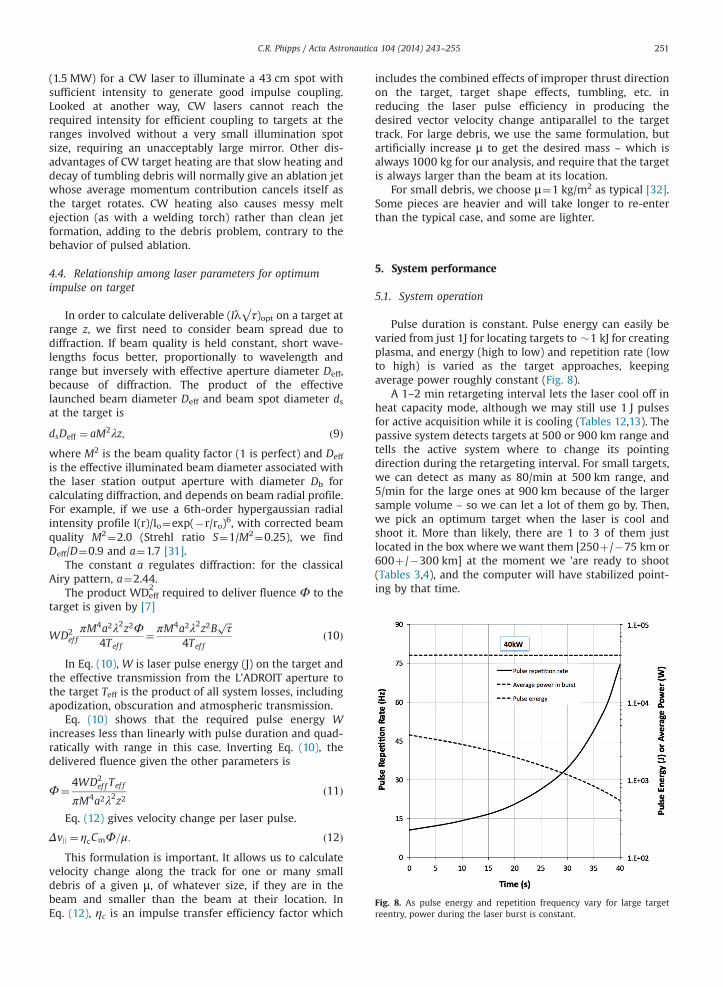
Fig. 8. As pulse energy and repetition frequency vary for large targetreentry, power during the laser burst is constant.
C.R. Phipps / Acta Astronautica 104 (2014) 243–255 251
(1.5 MW) for a CW laser to illuminate a 43 cm spot withsufficient intensity to generate good impulse coupling.Looked at another way, CW lasers cannot reach therequired intensity for efficient coupling to targets at theranges involved without a very small illumination spotsize, requiring an unacceptably large mirror. Other dis-advantages of CW target heating are that slow heating anddecay of tumbling debris will normally give an ablation jetwhose average momentum contribution cancels itself asthe target rotates. CW heating also causes messy meltejection (as with a welding torch) rather than clean jetformation, adding to the debris problem, contrary to thebehavior of pulsed ablation.
4.4. Relationship among laser parameters for optimumimpulse on target
In order to calculate deliverable (Iλ√τ)opt on a target atrange z, we first need to consider beam spread due todiffraction. If beam quality is held constant, short wave-lengths focus better, proportionally to wavelength andrange but inversely with effective aperture diameter Deff,because of diffraction. The product of the effectivelaunched beam diameter Deff and beam spot diameter dsat the target is
dsDeff ¼ aM2λz; ð9Þwhere M2 is the beam quality factor (1 is perfect) and Deff
is the effective illuminated beam diameter associated withthe laser station output aperture with diameter Db forcalculating diffraction, and depends on beam radial profile.For example, if we use a 6th-order hypergaussian radialintensity profile I(r)/Io¼exp(�r/ro)6, with corrected beamquality M2¼2.0 (Strehl ratio S¼1/M2¼0.25), we findDeff/D¼0.9 and a¼1.7 [31].
The constant a regulates diffraction: for the classicalAiry pattern, a¼2.44.
The product WDeff2
required to deliver fluence Φ to thetarget is given by [7]
WD2ef fπM4a2λ2z2Φ
4Tef f¼ πM4a2λ2z2B
ffiffiffiτ
p
4Tef fð10Þ
In Eq. (10), W is laser pulse energy (J) on the target andthe effective transmission from the L'ADROIT aperture tothe target Teff is the product of all system losses, includingapodization, obscuration and atmospheric transmission.
Eq. (10) shows that the required pulse energy Wincreases less than linearly with pulse duration and quad-ratically with range in this case. Inverting Eq. (10), thedelivered fluence given the other parameters is
Φ¼ 4WD2ef f Tef f
πM4a2λ2z2ð11Þ
Eq. (12) gives velocity change per laser pulse.
Δvjj ¼ ηcCmΦ=μ: ð12ÞThis formulation is important. It allows us to calculate
velocity change along the track for one or many smalldebris of a given μ, of whatever size, if they are in thebeam and smaller than the beam at their location. InEq. (12), ηc is an impulse transfer efficiency factor which
includes the combined effects of improper thrust directionon the target, target shape effects, tumbling, etc. inreducing the laser pulse efficiency in producing thedesired vector velocity change antiparallel to the targettrack. For large debris, we use the same formulation, butartificially increase μ to get the desired mass – which isalways 1000 kg for our analysis, and require that the targetis always larger than the beam at its location.
For small debris, we choose μ¼1 kg/m2 as typical [32].Some pieces are heavier and will take longer to re-enterthan the typical case, and some are lighter.
5. System performance
5.1. System operation
Pulse duration is constant. Pulse energy can easily bevaried from just 1J for locating targets to �1 kJ for creatingplasma, and energy (high to low) and repetition rate (lowto high) is varied as the target approaches, keepingaverage power roughly constant (Fig. 8).
A 1–2 min retargeting interval lets the laser cool off inheat capacity mode, although we may still use 1 J pulsesfor active acquisition while it is cooling (Tables 12,13). Thepassive system detects targets at 500 or 900 km range andtells the active system where to change its pointingdirection during the retargeting interval. For small targets,we can detect as many as 80/min at 500 km range, and5/min for the large ones at 900 km because of the largersample volume – so we can let a lot of them go by. Then,we pick an optimum target when the laser is cool andshoot it. More than likely, there are 1 to 3 of them justlocated in the box where we want them [250þ/�75 km or600þ/�300 km] at the moment we 'are ready to shoot(Tables 3,4), and the computer will have stabilized point-ing by that time.

Table 12Small Target Re-entry, 355 nm Station in Polar Orbit [Generic Target].
Target and station parameters Optical system parameters
Total Number in 560–960 km Altitude Band 100 k Typical Pulse Energy (J) 380Mass [nonspecific target] (kg) o 0.038 Pulse Repetition Frequency (Hz) 56Range z (km) 250 775 Laser output power (burst, kW) 21Operating Fraction [day/night] (%) 50 Wavelength λ (nm) 355Number of Passes for small debris Re-entry 1 Pulse Length τ (ns) 0.1Time to Re-enter one debris (Head-on, s) 10 Spot Size on Target dsp (m) 0.22Recovery/Retargeting interval (s) 120 Fluence on Target (kJ/m2) 8.5Primary Mirror Diameter (m) 1.5 Beam Quality Factor 2.0Push Efficiency ηc 0.50 Target Typical Crossfield Rate (mrad/s) 30Momentum Coupling Coefficient (N-s/MJ) 99 Detection Rate (/min) 15Time to Remove All Targets (mo.) 4.6 Time Average Laser Power (kW) 1.8Cost per small Object Removed ($) 310 Target Removal Rate (/operating hour) 30Cost per kg Removed ($)a 8 Acquisition Field of View (degrees) 60
Launch cost fraction (%) 31
a Cost is prorated to time per target. Cost model is approximate and proprietary to Photonic Associates, LLC, based on [11].
Table 13Large Target Raise/Lower 40km, 355nm Station in Polar Orbit [Generic Target].
Target and station parameters Optical system parameters
Total Number in 560–960 km Altitude Band 2 kmk Typical Pulse Energy (J) 1950Mass [nonspecific target] (kg) 1000 Pulse Repetition Frequency (Hz) 21Range z (km) 600 7300 Laser output power (burst, kW) 40Operating Fraction [day/night] (%) 100 Wavelength λ (nm) 355Number of Passes for Raising/Lowering 625 Pulse Length τ (ns) 0.1Shine Time per Interaction (s) 40 Spot Size on Target dsp (m) 0.50Recovery/Retargeting Interval (s) 60 Fluence on Target (kJ/m2) 8.5Primary Mirror Diameter (m) 1.5 Beam Quality Factor 2.0Push Efficiency ηc 1.0 Target Typical Crossfield Rate (mrad/s) 12Momentum Coupling Coefficient (N-s/MJ) 99 Detection Rate (/min) [much larger test vol.] 5Time to remove all targets (yrs) 4 Time average laser power (kW) 16Cost per target lowered/raised (k$) 280 Target Δv|| /pass (cm/s) 8.3Cost per kg removed ($)a 280 Acquisition field of view (degrees) 60
Launch cost fraction (%) 18
a Cost is prorated to time per target. Cost model is approximate and proprietary to Photonic Associates, LLC, based on [11].
C.R. Phipps / Acta Astronautica 104 (2014) 243–255252
In Fig. 4, only the beam projection Cassegrain telescopeis steered. In order to avoid aberration, this requires aperiscope arrangement of two flat mirrors inside the lasersystem to rotate and tilt the laser beam along with thetelescope. The reaction wheel and steering componentswill cause vibration onboard the spacecraft. The 0.5 μradpointing accuracy implied by Tables 3 and 4 is achieved byprecision piezoelectric transducers tilting the first of thesemirrors over a μrad range against a combination of fixedstar and angular accelerometer references with a 1 kHzfeedback loop bandwidth.
5.2. Small target re-entry
Table 12 shows performance for an optimized space-based UV laser system in producing small target re-entry.
Here, our goal is single interaction re-entry, becausepost-shot tracking of the small objects is difficult. For thisreason, we provide bursts of laser power sufficient to re-enter most of the small targets in a ten second interaction.In one interaction, we provide 236 m/s Δv, which is
sufficient for re-entry. It is interesting that this task canbe completed for 100 k targets in a little over four months,almost immediately removing the objects which commu-nicate the breakup instability. In small target mode, theduty factor is 50% because we need daylight to locatetargets.
5.3. Large target raising/lowering
For large targets �1000 kg, we can only make smallvelocity changes in one interaction [Table 13], so weassume groundbased tracking assistance to relocate aspecific object after an interaction and give us 100% dutyfactor. Typical Δv per interaction is 8.3 cm/s, so 625interactions are required to provide 43 m/s Δv necessaryto raise or lower the 1000 kg object by 40 km (see Section3.2) It will take about 4 years to complete this operationon 2000 one-ton objects, so we consider the majority ofsystem cost to be borne by this application. We note thatboth jobs can be done with a 2–15 kW average power lasercapable of 20–40 kW bursts lasting 10–40 s.

C.R. Phipps / Acta Astronautica 104 (2014) 243–255 253
We assume the total system mass in orbit is 10,000 kg.All costs are based on an assumed total system cost of560 M$, amortized over four years' operation, only 10% ofwhich is devoted to the small targets. This figure isassumed to include 410 M$ for the satellite, 145 M$ forlaunch and 5M$ for the cost of operations over the period.A Falcon 9 launcher would be suitable.
International cooperation
The most salient problem for L'ADROIT is not technical,but political. Designing, building and operating a lasersystem in space will require international cooperation toapply the best ideas, as well as to avoid concerns that it isactually a weapon system. Also, cooperation in its opera-tion will be needed to get permission for its use to removespecific debris objects.
Conclusions
We have reviewed a novel debris-clearing system usingan orbiting short-pulse UV laser system with only tens ofkW average power, which avoids the perceived risks ofpulsed laser debris removal.
We showed that our L'ADROIT configuration is moreagile and less costly than mechanical debris removaltechniques. It can handle tumbling objects, difficult formechanical systems. It is the only approach that can dealwith both small and large debris objects, and it will workon multi-ton objects. In general, we conclude that the costof removing a single piece of small debris is less than 1 k$.To raise or lower a generic large target, we expect a cost tobe of order 280 k$.
A spacebased UV laser system has special advantages inrange, rate of acquisition and interaction geometry thatdrive the estimated cost to a low level, compared togroundbased systems. The incremental cost of putting aL'ADROIT system in space is typically less than a 20%component of the total system cost.
This system can also be used to defend specific high-value assets from an anticipated debris encounter.
Fig. A1. Published data for impulse coupling coefficient on nonmetallicmaterials which might be found in space debris, compared with our
In Memoriam
This work is dedicated to Dr. Victor George (1938–2014), an early member of the laser program at LawrenceLivermore National Laboratory, who supported laser spacedebris removal concepts for many years.
theoretical model [19], vs. the parameter Iλ√τ. The modeled cases were:UV short pulses (“TURNER,” 248 nm, 22 ns), midspectrum short pulses(“GRUN,” 1.06 mm, 5 ns), midspectrum long pulses (“AFANAS'EV,”1.06 mm, 1.5 ms), and infrared long pulses (“GEMINI,” 10.6 mm, 1.8 ms).Materials are: (a): Ebonite rubber. (b, i): Carbon. (c): Silica phenolic. (d):Vamac rubber. (e): Buna-n rubber. (f): Kevlar epoxy. (g, h): Grafoil. (j):Carbon phenolic. (k): Graphite epoxy. (l): Carbon phenolic. (m): C-H foils.References for the data are found in [19]. [Used by permission, copyright1988, American Institute of Physics]. As a comparison, recent databy Fournier [29] for 200ps pulses on Al at 1.06 μm give Cm¼155N/MWat Iλ√τ ¼80W-√s/m (★). This data point agrees well with our modeland, because of Eq. (8), we expect a 30% larger value than Fournier'sat 355nm.
Acknowledgments
The author gratefully acknowledges Wolfgang Schall[33] for introducing the concept of spacebased laser activedebris removal in this journal 23 years ago, Joe Carroll,Tether Systems, Inc. for many discussions during this work,and Christophe Bonnal at CNES for his continuing patienceand interest in this project.
Appendix A. Variation of Impulse Coupling Coefficientwith Materials
To answer questions about the extent to which thenature of the material matters in laser plasma formation,Fig. A1 shows the variation of Cm with Iλ√τ for a largenumber of nometallic materials in 13 data sets, togetherwith the predictions of our theoretical model [22,23].Similar results were obtained for aluminum and its alloysusing nine additional data sets in [22]. In that work, datawere modeled in four cases with specific Saha equationsgiving ionization state Z vs. laser-induced plasma tem-perature (solid and dashed lines). Changes in the modelprediction for Cm vs Iλ√τ in each of the cases are due tochanges in the predicted Z, which is a function of tem-perature. The optimum value of Iλ√τ is the smallest valuethat produces the largest Cm. The value that we use for355 nm and 100 ps in this work, Cm¼100 NMW, is con-servative, because shorter wavelength and pulse durationthan the Fournier datum each give higher Cm than hisvalue, even though we operate slightly above optimumintensity for robust coupling on all materials. Data is notavailable for all materials at all wavelengths, intensities orpulse durations. Our theoretical model matches the varia-tion of Cm with the parameter Iλ√τ for a wide variety ofmaterials in the plasma regime for wavelengths from248 nm to 10.6 μm and pulse durations from 100 ps to1 ms, and shows that Cm varies no more than a factor-of-2above or below the model predictions for all these materi-als, starting from first principle calculations. These includealuminum and polymers such as kapton (a polymer likedata series m in the Figure) – the components of

C.R. Phipps / Acta Astronautica 104 (2014) 243–255254
multilayer insulation (MLI) – all of which fit the model towith factors of well. Physically, the parameter I√τ isintermediate between a fluence Iτ and an intensity I, andis the governing parameter in one dimensional heattransfer problems. The parameter Iλ√τ is the key para-meter governing Cm.
Appendix B. electrical and optical systems
B.1. laser
The laser is a laser-diode-pumped solid state oscillator-amplifier. We assume the amplifier medium is Nd:YAG(neodymium-doped yttrium aluminum garnet matrix), orNd:glass. It could be Yb:YAG. The latter has a lower energydefect and so creates less waste heat. This is because itspump band is almost the same as the lasing wavelength,which is not true for Nd:YAG. However, this choice leads totrickier laser design, including cryogenic operation. Energystorage density is about 0.66 kJ/liter in Nd:glass [34], andwith a density of 2.8 kg/liter, perhaps 10 kg for the entirelaser amplifier medium. By far the majority of systemmasswill be due to pump diode bars, their power supplies, solararrays, and heat dissipation equipment. In the LawrenceLivermore Laboratory LIFE laser design, a diode-pumpedNd:glass device intended to produce 18 Hz, 7 kJ, 355 nm
Table B1Fused silica damage Thresholds Φd
(J/cm2) at 100 ps.
λ( μm) Φd
1065 11532 8355 7266 3
Table B2Estimated L'ADROIT system parameters.
Laser output at 3rd harmonic (355 nm) 15
1st to 3rd harmonic conversion efficiency 0.85Diodes to 1st harmonic conversion efficiency 0.53Laser diode electrical to optical (e-o) efficiency 0.70Overall laser e-o efficiency 0.32Resulting laser electrical input 48Heat removal system 15Reaction torque motor 3Data and miscellaneous 1Total system electrical power requirement 67Solar array mass/area 0.85Solar array power/area 0.27Resulting solar array area 247Resulting solar array mass 210Passive detection mirror and mount mass 790Active mirror system and steering 1000Laser system mass including laser diodes 2500Electrical system mass including batteries 2500Cooling system mass 1500Spacecraft, thrusters and fuel mass 1500Total system mass 10,00
pulses with several ns pulse duration for a fusion reactor(130 kW average power, more than 8 times what werequire), optical component mass would have been about10,000 kg, and occupy about 31m3 [35,36]. The overallelectrical to optical efficiency ηe-o of the Nd:glass LIFE laserdesign at 355 nm was 21%. Improvements since then haveincreased this number. For example, the LIFE design uses75% for frequency conversion efficiency to the thirdharmonic at 351 nm, whereas 85% is now possible [37].Laser diodes can now be 70% rather than 66% efficient [37].Total transport efficiency is taken as 88%, but it can be verynear 100% in a small system such as ours. Taking all theseincremental factors together gives a net ηe-o¼ 32%.
B.2. optical damage Thresholds
Using [37] we have estimated the damage thresholdfluences for fused silica glass shown in Table B1 for ourcase at several wavelengths.
In the Table, we have taken the [38] value for 1nspulses and reduced it by √10 to estimate damage thresh-old at 100 ps. Fused silica is representative of opticalmaterials in the laser system. The table shows the mainreason we jettisoned our original 266 nm design for thissystem: damage threshold at the 4th harmonic is 2 timesless than for the 3rd. With 40 cm diameter, our moststressed high power beam components (zoom lens, convexmirror) operate comfortably a factor of 4 below the opticaldamage limit. At Brewster's angle, the laser amplifier diskswill operate at an additional factor of 1.8 below damagethreshold.
B.3 system power budget
Using best current figures, we estimate overall energybudget and solar array performance as shown in Table B2.As a benchmark for solar array parameters, we note thatthe 12-year-old International Space Station solar array
kW Reference
[37][36,39,40][41]
kWkWkWkWkWkg/m2 [42]kW/m2 [42,43]m2
kgkgkgkgkgkgkg
0 kg

C.R. Phipps / Acta Astronautica 104 (2014) 243–255 255
design generates 92 kW [38]. Batteries store energy forbursts in heat-capacity mode.
References
[1] Gravity, movie 2013 produced by Esperanto Filmoj and HeydayFilms, directed by Alfonso Cuarón.
[2] D. Kessler, B. Cour-Palais, Collision Frequency of Artificial Satellites:The Creation of a Debris Belt, J. Geophys. Res. 83 (1978) 2637–2646.
[3] J. Henderson, S. Nikolaev, et al., Intelligent sensor tasking for spacecollision mitigation, Proc. SPIE 7691 (2010) 76910L.
[4] L. Simms, V. Riot, et al., Optical payload for the STARE pathfindermission, Proc. SPIE 8044 (2011) 804406.
[5] P. Brudieu, B. Lazare, French Policy for Space Sustainability andPerspectives, in: Proceedings of the 16th ISU Symposium on SpaceActivities, Strasbourg, 2012.
[6] P. Maier, et al. ISU Team Project: an Integral view on space debrismitigation and removal, In: Proceedings of the 6th EuropeanConference on Space Debris, Darmstadt, 22–25 April 2013.
[7] C. Phipps, et al., Removing orbital debris with lasers, Adv. Space Res.49 (2012) 1283–1300.
[8] C. Phipps, Catcher's Mitt as an alternative to laser space debrismitigation, AIP Conf. Proc. 1278 (2010) 509–514.
[9] C. Bonnal, High level requirements for an operational space debrisdeorbiter. In: Proceedings of the NASA/DARPA International Con-ference on Orbital Debris Removal, Chantilly, VA, 2009.
[10] J. Mason, J. Stupl, et al.. Orbital Debris Collision Avoidance,arXiv:1103.1690v1 [physics.space-ph], 2011.
[11] J. Campbell, Project ORION: Orbital Debris Removal Using Ground-Based Sensors and Lasers, NASA Marshall Spaceflight Center Tech-nical Memorandum 108522, 1996.
[12] C. Bombardelli, H. Urrutxua, M. Merino, E. Ahedo, J. Peláez,L. Summerer, A Plan to Deorbit Envisat, in: Proceedings of the 2ndEuropean Workshop on Active Debris Removal, Paris, 2012.
[13] V. Kirchoff, D. Pinheiro, D., Wavelength dependence of aerosoloptical thickness in the UV-B band, Geophys. Resch. Lett. 29 (2002)58-1–58-4.
[14] Klinkrad H., Space Debris, Models and Risk Analysis, Springer Praxis(2006) and updates provided by H. Krag (2014).
[15] H. Kogelnik, T. Li, Laser beams and resonators, Appl. Opt. 5 (1996)1550.
[16] E. Köse, R. Perline, Double-mirror catadioptric sensors with ultra-wide field of view and no distortion, Appl. Opt. 53 (2014) 528–536.
[17] C. Phipps, S. Bodner, J. Shearer, Reflective optics system for uniformspherical illumination, Appl. Opt. 14 (1975) 985–991.
[18] C.W. Allen, Astrophysical Quantities, Athlone, London, 1973.[19] W.L. Wolfe, G.J. Zissis, The Infrared Handbook, Office of Naval
Research, Washington, D.C, 1978.[20] J.P. Reilly, The Infrared Handbook, Office of Naval Research, Camp-
bell, 1996.[21] C. Phipps, Appl. Surf. Sci. 252 (2006) 4836–4844. (2006).[22] C. Phipps, et al., Impulse Coupling to Targets in Vacuum by KrF, HF
and CO2 Lasers, J. Appl. Phys. 64 (1988) 1083–1096.[23] C. Phipps, M. Birkan, et al., Laser ablation propulsion, J. Propuls.
Power 26 (2010) 609–637.[24] P. Combis, P. B, B. Cazalis, J. David J, A. Froger A, M. Louis-Jacquet,
M. B, B. Meyer, G. Nierat G, A. Saleres A, G. Sibille G, G. Thiell G.,F. Wagon F, Low fluence laser-target coupling, Laser Particle Beams 9(1991) 403–420.
[25] A. Saleres, B Cazalis, P. Combis, J. David, B. Meyer, G. Nierat, G. Sibille,G. Thiell, F. Wagon, Couplage Thermique et Mécanique dans L'inter-action Laser-Matière a Éclairement Modéré, CEA Limeil-Valentonreport 4eme Trimestre, 1992.
[26] Yu.V. Afanas’ev, N.G. Basov, O.N Krokhin, N.V. Morachevskii, G.V. Sklizkov, Gas-dynamic processes in irradiation of Solids, Sov.Phys. Tech. Phys. 14 (1969) 669–676.
[27] C. Phipps, J. Luke, D. Funk, D. Moore, J. Glownia, T. Lippert, Laserimpulse coupling at 130fs, Appl. Surf. Sci. 252 (2006) 4838–4844.
[28] C. Phipps, An alternate treatment of the vapor-plasma transition, Int.J. Aerosp. Innov. 3 (2011) 45–50.
[29] K. Fournier, LASNEX calculations of laser-coupling coefficients for Altargets, Lawrence Livermore Laboratory presentation UCRL-Pres226849 (2006) 29.
[30] C. Phipps, A laser-optical system to re-enter or lower low Earth orbitspace debris, Acta Astronautica 93 (2014) 418–429.
[31] C. Phipps, S. Thomas D. Watkins, Effect of Nonlinear Refraction onBeam Brightness in Laser Fusion Applications, Proc. Intl. Conf. onLasers'79, 1980.
[32] H. Klinkrad, ibid. 2006, Fig. 3.3, p. 70.[33] W. Schall, Orbital debris removal by laser radiation, Acta Astronaut.
24 (1991) 343.[34] W. Koechner, Solid State Laser Engineering, Springer Verlag, 2006.[35] K. Fournier, Lawrence Livermore Natinal Laboratory (2014), private
communication.[36] A. Bayramian, A. Erlandson, Comparison of Nd:phosphate glass,
Yb:YAG and Yb:S-FAP laser beamlines for laser inertial fusionenergy, LLNL-PRES-581113, 2012. https://www.lasers.llnl.gov/workshops/hec_dpssl_2012/pdf/9-13-12/A.Erlandson.pdf.
[37] D. Neely, Rutherford Appleton Laboratory, UK (2014), privatecommunication.
[38] http://www.esa.int/esapub/br/br202/br202.pdf.[39] N. Kuzuu, et al., Laser-induced bulk damage of various types of silica
glasses at 532nm and 355nm, Japanese J. Appl. Phys 43 (2004)2547–2548.
[40] A. Bayer, B. Köhler, A. Noeske, M. Küster, D. Irwin, S. SPatterson,J. Biesenbach, J. Scalable and modular diode laser architecture forfiber coupling that combines high-power, high-brightness and lowweight. paper 2014-02-04, Photonics West, 2014.
[41] J.J. Noekum, Overview on New Diode Lasers for Defense Applica-tions. in: Proceedings of the SPIE Europe Security and Defense, 2012⟨http://spie.org/x4304.xml⟩.
[42] BEPI-COLUMBO: Haag, M. (2006) Lightweight fiber-coupled diodelaser pump module for the BeipColumbo laser altimeter. In: Pro-ceedings of the 2nd ESA-NASAWorking Meeting on Optoelectronics,Noordwijk, Netherlands.
[43] N. Fatemi, et al. (2000). Solar array trade studies between very highefficiency multi-junction and Si space solar cells. Proc. 28th IEEEPVSC, Anchorage, Alaska.
Claude Phipps earned B.S. and M.S. degreesfrom the Massachusetts Institute of Technol-ogy, and a Ph.D. from Stanford University in1972. He worked in the Inertial ConfinementFusion Program at Lawrence LivermoreLaboratory and, from 1974 to 1995, in theAdvanced Optical Systems Group at LosAlamos National Laboratory (LANL). There,he conducted a research program onmechanical and thermal coupling of pulsedlasers to targets using high-energy-laserfacilities in the United States and United
Kingdom, and developed a model for vacuumlaser impulse prediction. From 1994 to 1995, he was Associate Director ofthe Alliance for Photonic Technology at LANL. In 1995, he formedPhotonic Associates, which is devoted to applications of laser spacepropulsion. He is the author of 124 peer-reviewed papers, 120 conferencepresentations including 40 invited talks and a keynote, has contributed totwo textbooks on laser ablation phenomena, and has organized andchaired eleven symposia on high-power laser ablation and beamedenergy propulsion.