Embed Size (px)
Citation preview

Contents lists available at SciVerse ScienceDirect
Signal Processing
Signal Processing 93 (2013) 605–619
0165-16
http://d
$ Thi
Flander
G.0206.n Corr
(ETRO),
Belgium
E-m
journal homepage: www.elsevier.com/locate/sigpro
Crack detection and inpainting for virtual restoration of paintings:The case of the Ghent Altarpiece$
B. Cornelis a,c,n, T. Ruzic b,c, E. Gezels d, A. Dooms a,c, A. Pizurica b,c, L. Platisa b,c, J. Cornelis a,M. Martens d, M. De Mey e, I. Daubechies f
a Department of Electronics and Informatics (ETRO), Vrije Universiteit Brussel (VUB), Pleinlaan 2, B-1050 Brussels, Belgiumb Department for Telecommunications and Information Processing (TELIN), Ghent University (UGent), Sint-Pietersnieuwstraat 4, B-9000 Ghent, Belgiumc Interdisciplinary Institute for Broadband Technology (IBBT), Gaston Crommenlaan 8 (box 102), B-9050 Ghent, Belgiumd Department of Art, Music and Theatre Sciences, Ghent University (UGent), Blandijnberg 2, B-9000 Ghent, Belgiume The Flemish Academic Centre for Science and the Arts (VLAC), Hertogsstraat 1, B-1000 Brussels, Belgiumf Mathematics Department, Duke University, Box 90320, Durham, NC, USA
a r t i c l e i n f o
Article history:
Received 23 August 2011
Received in revised form
19 March 2012
Accepted 10 July 2012Available online 25 July 2012
Keywords:
Crack detection
Patch-based inpainting
Digital restoration
Ghent Altarpiece
Adoration of the Mystic Lamb
84/$ - see front matter & 2012 Elsevier B.V. A
x.doi.org/10.1016/j.sigpro.2012.07.022
s research was supported by the Fund for
s (FWO) (PhD fellowship of Bruno Corn
08 and G021311N).
esponding author at: Department of Electron
Vrije Universiteit Brussel (VUB), Pleinlaan 2
. Tel.: þ32 26291671.
ail address: [email protected] (B. Corne
a b s t r a c t
Digital image processing is proving to be of great help in the analysis and documenta-
tion of our vast cultural heritage. In this paper, we present a new method for the virtual
restoration of digitized paintings with special attention for the Ghent Altarpiece (1432),
a large polyptych panel painting of which very few digital reproductions exist. We
achieve our objective by detecting and digitally removing cracks. The detection of
cracks is particularly difficult because of the varying content features in different parts
of the polyptych. Three new detection methods are proposed and combined in order to
detect cracks of different sizes as well as varying brightness. Semi-supervised clustering
based post-processing is used to remove objects falsely labelled as cracks. For the
subsequent inpainting stage, a patch-based technique is applied to handle the noisy
nature of the images and to increase the performance for crack removal. We
demonstrate the usefulness of our method by means of a case study where the goal
is to improve readability of the depiction of text in a book, present in one of the panels,
in order to assist paleographers in its deciphering.
& 2012 Elsevier B.V. All rights reserved.
1. Introduction
In this work, we focus on crack detection and inpaint-ing in the Ghent Altarpiece and extend upon the workintroduced in [1]. The polyptych, dated by inscription1432, was painted by Jan and Hubert van Eyck and isconsidered as one of their most important masterpieces
ll rights reserved.
Scientific Research
elis and Projects
ics and Informatics
, B-1050 Brussels,
lis).
known all over the world. It is still located in the SaintBavo Cathedral in Ghent, its original destination.
Cracking is one of the most common deteriorationsfound in old masters paintings; it is a sign of theinevitable aging of materials and constitutes a record oftheir degradation. Generally speaking, a crack (or craque-
lure) appears in paint layers when pressures developwithin or on it through the action of various factors andcause the material to break [2]. The state of preservationof a painting is mainly influenced by climate changes suchas variations in temperature, relative humidity or pres-surization (e.g. during transport via air) [3]. As for most15th century Flemish paintings on Baltic oak, fluctuationsin relative humidity, causing the wooden support toshrink or expand, are the main causes for age crack

B. Cornelis et al. / Signal Processing 93 (2013) 605–619606
formation. Age related or mechanical cracks can affect theentire paint layer structure, including both the prepara-tion and the paint layers on it. Age cracks are to bedistinguished from premature cracking [2]. The latter aremore dull-edged than those formed when aging andoriginate in only one of the layers of paint. They generallyreveal a defective technical execution at the paintingstage, such as not leaving enough time for a layer todry, or applying a layer that dries faster than the under-lying one. A third type is varnish cracks, formed only inthe varnish layer, when it becomes brittle throughoxidation.
Cracks form an undesired pattern that can be eitherrectangular, circular, web-shaped, unidirectional, tree-shaped or even completely random. The way in whichthey manifest themselves and spread partly dependsupon the choice of materials and methods used by theartist. This makes cracks useful for judging authenticity,as is proposed in [4]. Cracks can also assist conservatorsby providing clues to the causes of degradation of thepaint surface. This can be used for degradation monitoringof the paint layer or a more in-depth study on whichfactors contribute to the formation of cracks, so that stepscan be taken to reduce them [5]. The potential of usingcracks as a non-invasive means of identifying the struc-tural components of paintings is highlighted in [6]. Thecorrelation between the network of cracks on the surfaceand the structure of the panel below is also investigatedin [2] by using multi-layered X-ray radiography. An areawhich is thought to be of great interest to art conservationis content-based analysis where cracks are used forcontent-based retrieval of information from image data-bases [3].
Digital image processing can automatically detect crack-like patterns. In the literature, this process is often referredto as ridge-valley structure extraction [7]. Many types ofimages contain similar elongated structures (e.g. medicalimages of veins and vessels [8], images of fingerprints andsatellite imagery of rivers and roads) and the common goalis to extract or detect these crack-like patterns in order toseparate them from the rest of the image. An overview ofdifferent crack detection techniques can be found in [5].These include different types of thresholding, the use ofmulti-oriented filters (such as Gabor filters) and a plethoraof morphological transforms.
In the context of the virtual restoration of digitizedpaintings, crack detection is often treated side-by-sidewith crack removal. Inpainting, which is the imagerestoration task of filling in missing parts of the image,is used for this purpose. The literature contains a vastnumber of general inpainting methods which can beroughly separated into two groups: pixel-based andpatch-based methods. Pixel-based methods aim at repla-cing one missing pixel at the time [9,10] by speciallyfocusing on structure propagation, i.e. propagation of linesand object contours, from the boundaries of the missingregion to its center. Patch-based methods [11–14], on theother hand, fill in the missing region patch-by-patchensuring in that way better texture propagation. Theyalso consider structural propagation by introducing acertain priority in which the patches are visited.
A virtual restoration system to remove cracks ondigital images of paintings was developed in [15]. Theirmethod is based on a semi-automatic crack detectionprocedure, where users need to specify a location believedto belong to a crack network. The algorithm will thentrack other suspected crack points based on two mainfeatures, absolute gray-level and crack uniformity. Oncethe algorithm has completely detected cracks, they can beremoved by interpolation. In [16–18] crack patterns aredetected by thresholding the output of a morphologicaltop-hat transform. Cracks are subsequently separatedfrom brushstrokes (i) by using the hue and saturationinformation in the HSV or HSI colour space and feedingit to a neural network or (ii) by letting a user manuallyselect seed points. Finally, the cracks are inpainted usingorder statistics filtering for interpolation [17], controlledanisotropic diffusion [16] or patch-based texture synth-esis [18].
The cracks considered here are particular in a numberof ways. Their width ranges from very narrow and barelyvisible to larger areas of missing paint. Furthermore,depending on the painting’s content, they appear asdark thin lines on a bright background or vice versa,bright thin lines on a darker background. In Section 2 weintroduce three different detection schemes, each able todetect bright and dark cracks and each having its ownstrength. Since this masterpiece contains many detailsand some of the brushstrokes are of similar colour andstructure as the cracks, we introduce a semi-supervisedclustering based post-processing step to remove falsepositives. The detection is finalized by combining thecleaned crack maps of each of the three methods usinga simple voting scheme.
Additionally, the bright borders that are presentaround some of the cracks (and are accentuated by theway the data set was acquired) cause incorrect andvisually disturbing inpainting results. These borders arethe result of two factors: where a crack is forming, thepaint is pushed upwards and forms a small inclination.Light gets reflected on the ridges caused by this crackingand makes them appear brighter than their immediatesurroundings. Also, during previous cleaning, the surfacepaint on these elevated ridges may have been accidentallyremoved, revealing parts of the underlying white pre-paration layer. Section 3 elaborates on the improvedpatch-based inpainting for the digital filling of cracksand the inpainting results.
In Section 4 the practicability of our technique isconfirmed by means of a case study which consists ofimproving the readability of depicted text in a very smalldetail in one of the panels. We end the paper withconcluding remarks, presented in Section 5.
2. Crack detection
Cracks can visually be categorized into two classes,bright cracks on a dark background or dark cracks on abright background (see Fig. 1). Mainly dark cracks aretreated in the literature, where they are typically consideredas having low luminance and being local (grayscale) inten-sity minima with elongated structure [19]. Different crack

B. Cornelis et al. / Signal Processing 93 (2013) 605–619 607
detection techniques include simple thresholding, linedetectors and various morphological filters (see [5] for anoverview). Thresholding does generally not work well dueto the noisy nature of the images and the presence of other‘‘crack-like’’ structures in the image. The varying quality ofthe images and the difficulty of detecting cracks in low-contrast zones justifies several pre-processing steps. Weintroduce three different crack detection techniques thatcan be applied for the detection of both dark and brightcracks, each having its own strength. A semi-automaticclustering based post-processing step is applied to reducethe number of false detections. We subsequently combinethe results of each technique and hence put to use theirrespective strengths. The procedure for the entire crackdetection is shown in Fig. 2.
Furthermore, we identified the need to detect brightborders that surround some of the cracks (as depicted indetail in the upper right corner of Fig. 1 and in Fig. 4)because they cause incorrect and visually unpleasinginpainting results. We will show in Section 3 that theirdetection and treatment as missing regions lead toimproved inpainting.
2.1. Pre-detection processing
The detection of cracks in low contrast areas is aparticularly difficult task. To deal with this problem,we introduce a local contrast enhancement step fordarker zones in the image prior to crack detection. This
Fig. 1. Crack types: dark cracks on bright background (top), and bright
cracks on dark background (bottom). The width of the mouth is 2.86 cm
(approximately 1.13 in) on the panel.
Pre-detection
processing
Oriented elongated
filters
Multiscale top-hat
K-SVD
Post-process
Fig. 2. Workflow for the entire crack detection procedure. The optional inpain
around the crack are prominently present (e.g. in Fig. 21).
pre-processing step consists of taking the weighted aver-age of the original grayscale image (Iorig) and its locallycontrast enhanced version (ICLAHE) such that only darkerareas are replaced with a contrast enhanced version. Theresulting image I is constructed as follows:
I¼ ð1�wÞIorigþwICLAHE, ð1Þ
where the high contrast image ICLAHE is constructed byusing contrast limited adaptive histogram equalization
(CLAHE) [20] and the weights w for each pixel aredetermined by blurring (Gaussian kernel with s¼ 15and mask size 45�45) the inverted image Iorig (see Fig. 3).
Due to the noisy nature of the images we performanisotropic diffusion [21] on image I as isotropic blurringwould remove edges too much, which is in fact what wewant to detect. We work on high resolution scans oforiginal photographic negatives (Kodak Safety Film13�18 cm) taken by a professional photographer, thelate Rev. Alfons Dierick, whose material is currentlypreserved in the Alfons Dierickfonds archive of the GhentUniversity. The capturing process (i.e. field of view, light-ing, etc.) is undocumented and the images are noisy(an example is given in Fig. 4). Not only were differentchemical processes used to develop the negatives, butsome of them were also acquired at different resolutionsand with different scanning hardware. In strong contrastto the medical world, where standardization made com-mon image processing tools possible, it is very challen-ging to find a global parameter set for all images underinvestigation. The data set being heterogeneous in nature,the amount of anisotropic diffusion is determined heur-istically: the higher the resolution of the images, the moreiterations are chosen for the diffusion.
2.2. Detection methods
Three novel crack detection methods are applied forthe detection of both dark and bright cracks. Thesetechniques have complementary strengths, which areexplained in Section 2.4.
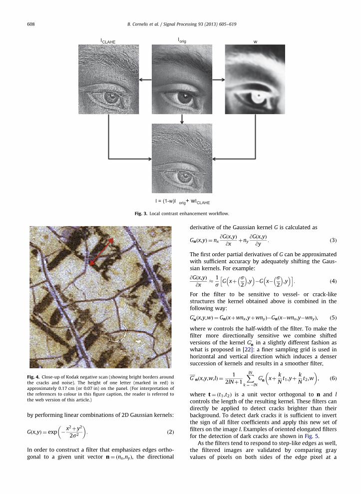
2.2.1. Filtering with oriented elongated filters
Oriented elongated filters (see Fig. 5) were originallyintroduced to detect and enhance blood vessels of differentthicknesses and orientations in medical images [22]. Theyare used here for the detection of cracks and are obtained
ing Merging Inpainting
pre-processing
ting preprocessing (see Section 2.5) is applied whenever bright borders
w
I = (1-w)I orig+ wICLAHE
Iorig ICLAHE
Fig. 3. Local contrast enhancement workflow.
Fig. 4. Close-up of Kodak negative scan (showing bright borders around
the cracks and noise). The height of one letter (marked in red) is
approximately 0.17 cm (or 0.07 in) on the panel. (For interpretation of
the references to colour in this figure caption, the reader is referred to
the web version of this article.)
B. Cornelis et al. / Signal Processing 93 (2013) 605–619608
by performing linear combinations of 2D Gaussian kernels:
Gðx,yÞ ¼ exp �x2þy2
2s2
� �: ð2Þ
In order to construct a filter that emphasizes edges ortho-gonal to a given unit vector n¼ ðnx,nyÞ, the directional
derivative of the Gaussian kernel G is calculated as
Gnðx,yÞ ¼ nx@Gðx,yÞ
@xþny
@Gðx,yÞ
@y: ð3Þ
The first order partial derivatives of G can be approximatedwith sufficient accuracy by adequately shifting the Gaus-sian kernels. For example:
@Gðx,yÞ
@x�
1
sG xþ
s2
� �,y
� ��G x�
s2
� �,y
� �h i: ð4Þ
For the filter to be sensitive to vessel- or crack-likestructures the kernel obtained above is combined in thefollowing way:
G0nðx,y,wÞ ¼ Gnðxþwnx,yþwnyÞ�Gnðx�wnx,y�wnyÞ, ð5Þ
where w controls the half-width of the filter. To make thefilter more directionally sensitive we combine shiftedversions of the kernel G0n in a slightly different fashion aswhat is proposed in [22]: a finer sampling grid is used inhorizontal and vertical direction which induces a densersuccession of kernels and results in a smoother filter,
G0nðx,y,w,lÞ ¼1
2lNþ1
XlNk ¼ �lN
G0n xþk
Nt1,yþ
k
Nt2,w
� �, ð6Þ
where t¼ ðt1,t2Þ is a unit vector orthogonal to n and l
controls the length of the resulting kernel. These filters candirectly be applied to detect cracks brighter than theirbackground. To detect dark cracks it is sufficient to invertthe sign of all filter coefficients and apply this new set offilters on the image I. Examples of oriented elongated filtersfor the detection of dark cracks are shown in Fig. 5.
As the filters tend to respond to step-like edges as well,the filtered images are validated by comparing grayvalues of pixels on both sides of the edge pixel at a
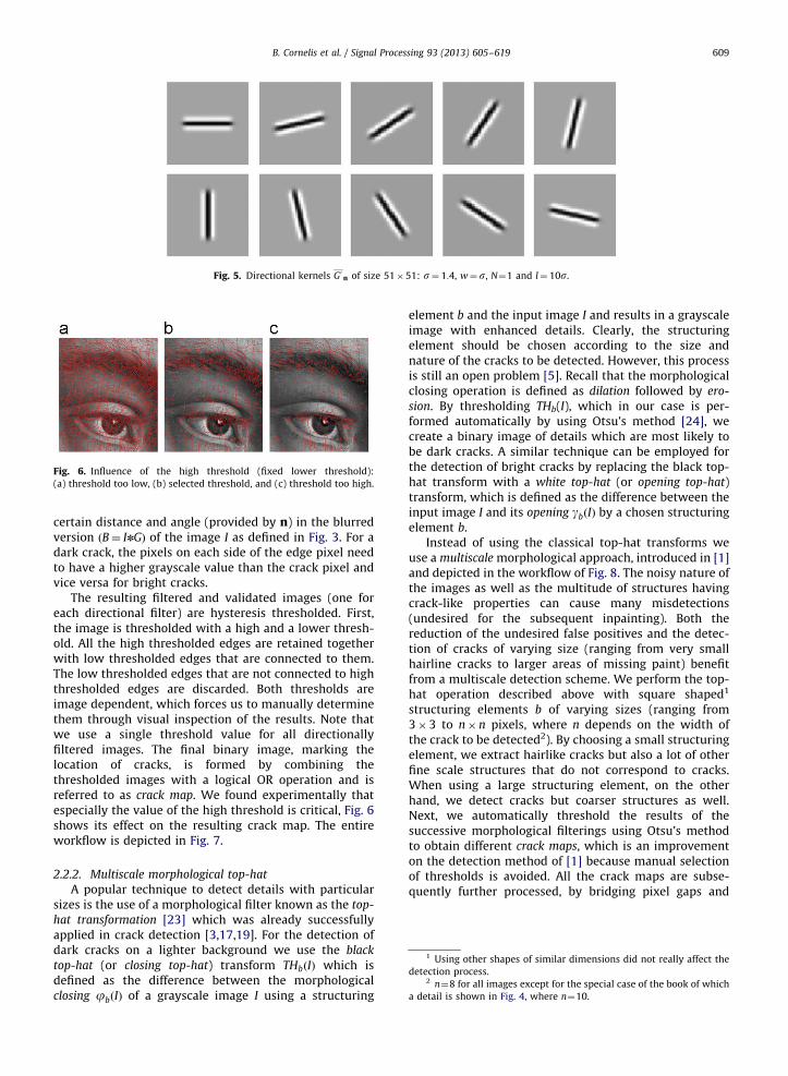
Fig. 5. Directional kernels G0 n of size 51�51: s¼ 1:4, w¼ s, N¼1 and l¼ 10s.
Fig. 6. Influence of the high threshold (fixed lower threshold):
(a) threshold too low, (b) selected threshold, and (c) threshold too high.
1 Using other shapes of similar dimensions did not really affect the
detection process.2 n¼8 for all images except for the special case of the book of which
a detail is shown in Fig. 4, where n¼10.
B. Cornelis et al. / Signal Processing 93 (2013) 605–619 609
certain distance and angle (provided by n) in the blurredversion ðB¼ InGÞ of the image I as defined in Fig. 3. For adark crack, the pixels on each side of the edge pixel needto have a higher grayscale value than the crack pixel andvice versa for bright cracks.
The resulting filtered and validated images (one foreach directional filter) are hysteresis thresholded. First,the image is thresholded with a high and a lower thresh-old. All the high thresholded edges are retained togetherwith low thresholded edges that are connected to them.The low thresholded edges that are not connected to highthresholded edges are discarded. Both thresholds areimage dependent, which forces us to manually determinethem through visual inspection of the results. Note thatwe use a single threshold value for all directionallyfiltered images. The final binary image, marking thelocation of cracks, is formed by combining thethresholded images with a logical OR operation and isreferred to as crack map. We found experimentally thatespecially the value of the high threshold is critical, Fig. 6shows its effect on the resulting crack map. The entireworkflow is depicted in Fig. 7.
2.2.2. Multiscale morphological top-hat
A popular technique to detect details with particularsizes is the use of a morphological filter known as the top-
hat transformation [23] which was already successfullyapplied in crack detection [3,17,19]. For the detection ofdark cracks on a lighter background we use the black
top-hat (or closing top-hat) transform THbðIÞ which isdefined as the difference between the morphologicalclosing jbðIÞ of a grayscale image I using a structuring
element b and the input image I and results in a grayscaleimage with enhanced details. Clearly, the structuringelement should be chosen according to the size andnature of the cracks to be detected. However, this processis still an open problem [5]. Recall that the morphologicalclosing operation is defined as dilation followed by ero-
sion. By thresholding THb(I), which in our case is per-formed automatically by using Otsu’s method [24], wecreate a binary image of details which are most likely tobe dark cracks. A similar technique can be employed forthe detection of bright cracks by replacing the black top-hat transform with a white top-hat (or opening top-hat)transform, which is defined as the difference between theinput image I and its opening gbðIÞ by a chosen structuringelement b.
Instead of using the classical top-hat transforms weuse a multiscale morphological approach, introduced in [1]and depicted in the workflow of Fig. 8. The noisy nature ofthe images as well as the multitude of structures havingcrack-like properties can cause many misdetections(undesired for the subsequent inpainting). Both thereduction of the undesired false positives and the detec-tion of cracks of varying size (ranging from very smallhairline cracks to larger areas of missing paint) benefitfrom a multiscale detection scheme. We perform the top-hat operation described above with square shaped1
structuring elements b of varying sizes (ranging from3�3 to n�n pixels, where n depends on the width ofthe crack to be detected2). By choosing a small structuringelement, we extract hairlike cracks but also a lot of otherfine scale structures that do not correspond to cracks.When using a large structuring element, on the otherhand, we detect cracks but coarser structures as well.Next, we automatically threshold the results of thesuccessive morphological filterings using Otsu’s methodto obtain different crack maps, which is an improvementon the detection method of [1] because manual selectionof thresholds is avoided. All the crack maps are subse-quently further processed, by bridging pixel gaps and

Create directional
filters
Validate filtered image
Threshold w.
hysteresis
Combine maps (OR) ilt
ma
For each filtered image
Filtering
Fig. 7. Filtering with elongated directional filters workflow.
Base map
Top-Hat +
thresholding Remove small
objects
Crack map Connect objects
Original
3x3
nxn
Fig. 8. Multiscale morphological top-hat workflow.
B. Cornelis et al. / Signal Processing 93 (2013) 605–619610
removing isolated or small groups of pixels as much aspossible.3
We now combine the resulting crack maps fromsuccessive scales in a novel way. The crack maps of thethree smallest scales are added to form our base map
which is used as a reference for selecting cracks in crackmaps corresponding to coarser scales. The final crack mapresults from the base map by adding only objects(i.e. groups of connected pixels) from maps at coarserscales that are connected to the base map. This way ofworking has the major advantage that unwanted largerstructures such as the mustache of Adam in Fig. 1 or theletters in the book image depicted in the example of Fig. 8,more often detected at larger scales, will not be includedin the final map while cracks are still allowed to growthrough successive scales.
3 Standard parameterless Matlab functions are used in the following
sequence: bridge, clean and fill. These are followed by an additional
cleaning step, removing objects of size smaller than 20, 30, 40,y, 70
pixels for the six successive morphological filtered images.
2.2.3. K-SVD for crack enhancement
The third technique proposed in this paper relies onthe use of the K-SVD algorithm [25], which is used forconstructing and adapting dictionaries in order to achievesparse signal representations and which was neverapplied before in a crack detection context. It is aniterative method that alternates between sparse codingof the data based on the current dictionary and theupdating of dictionary atoms to better fit the data.
The K-SVD algorithm works on small (usually over-lapping) patches x 2 Rn of size
ffiffiffinp�
ffiffiffinp
. The learning ofthe over-complete dictionary D 2 Rn�k with a fixed num-ber of atoms k and sparsity constraint L (i.e. each patch iscomposed of no more than L dictionary atoms) can bedescribed by the following optimization problem:
mina,D
JX�DaJ22 s:t: JalJ0rL, ð7Þ
where the column vectors (xl) of X are M image patches onwhich the dictionary D is learned. Each dictionary atomdi 2 D, for i¼ 1 . . . k, is a unit vector in the ‘2-norm. Thecolumn vector al of a is the sparse coefficient matrix vectorcorresponding to the patch xl and JalJ0 denotes the number

Fig. 10. Candidate image patches, Ic, for training of dictionary.
B. Cornelis et al. / Signal Processing 93 (2013) 605–619 611
of non-zero elements in the vector. K-SVD is an iterativemethod specifically designed to minimize the energy of (7)and where each iteration consists of two steps. The first oneis the sparse coding step which addresses the problem offinding the best decomposition Dal for each patch xl. To thisend, a greedy orthogonal matching pursuit (OMP) is used. Thesecond step, called the dictionary update step, optimizes theleast-square problem (i.e. the ‘2-norm in (7)) for each atomindividually while keeping the remaining atoms fixed andupdates the corresponding non-zero coefficients in a. K-SVDis used in this context as a method for enhancing crackswithin the image by training an optimal dictionary D for eachimage and altering the coefficient matrix a during recon-struction in an appropriate way.
A dictionary (k¼128) is trained on overlapping patches ofthe image I, containing cracks, hence producing an over-complete dictionary tweaked to that image. Patches must besufficiently large to capture crack-like edges ð
ffiffiffinp¼ 16Þ and
the sparsity constraint is very strict (L equal to 1 is typicallychosen). After training (using 20 iterations, and on a suffi-ciently large number of patches), some dictionary elementswill contain information for the ‘‘optimal’’ representation ofcracks due to the strong sparsity constraint. We use thetrained dictionary to reconstruct an image patch Ic containingonly cracks, which obviously favours the usage of crack-likedictionary elements. This can be observed in the histogram ofdictionary usage depicted in Fig. 9. Choosing an appropriateIc is straightforward: examples are given in Fig. 10. Whenreconstructing the image I, the number of elements in thecoefficient matrix a, corresponding to less used dictionaryelements for Ic are put to zero. Note that the dictionary itselfremains unaltered. The rule for zeroing out coefficients is asfollows:
8l, ali ¼ali if Ja0iJ04b maxJa0iJ0,
0 otherwise,
(ð8Þ
where a0 is the coefficient matrix when reconstructing thecrack-only image patch Ic, Ja0iJ0 the corresponding total usage
d i o
ccur
renc
e
Initial dictionary D
Most used d i
Fig. 9. Dictionary usage histogram and
of dictionary element di, l the index of the patch extractedfrom I and b a parameter controlling the amount of coeffi-cients to put to zero. The default value for b is chosen as 0.5and its value is lowered when it is observed that aninsufficient number of cracks are reconstructed, but thishappens rarely and hence user interaction is kept to aminimum. Through this procedure, non-crack dictionaryelements are omitted during the reconstruction of I.
Note that the DC component of each patch is sub-tracted before training and reconstruction, which resultsin a reconstructed image that can contain negative valuesas well. As a final step the image is hysteresis thresholdedin the same fashion as described in Section 2.2.1 for thedetection of bright cracks while for the detection of darkcracks the reconstructed image needs to be inverted first(results are shown in Fig. 11).
2.3. k-Means clustering based semi-automatic
post-processing
In the three proposed methods some objects, having asimilar structure as cracks (such as eyebrows, eyelashesand the mustache in the Panel depicting Adam or theletters of the book in the Annunciation to Mary panel) are
di = || α ||
0
th
most used di ðth¼ b maxJa0iJ0).

Fig. 11. K-SVD results (left: original; middle: reconstructed (inverted); right: thresholded).
Fig. 12. Results of detection with K-SVD (left: original detection; right:
after post-processing with k-means clustering).
Fig. 13. Results of detection with elongated filters (left: original detection;
right: after post-processing with k-means clustering).
B. Cornelis et al. / Signal Processing 93 (2013) 605–619612
sometimes falsely labelled as cracks. We propose aclustering based semi-automatic method to assist infiltering out those structures.
First the binary map, obtained by applying one of themethods described above, is thinned to obtain one-pixelwide cracks [26]. Crack pixels are linked together into listsof coordinate pairs,4 where a crack junction is encoun-tered. The list is terminated and a separate list is gener-ated for each of the branches. In this manner, each crack isbroken down into segments which can be treated asseparate objects. For each of these objects, a number offeatures are calculated: colour (the object’s mean colourvalues in RGB and HSV colour space) and physical proper-ties such as length, orientation and eccentricity. Next tothese, the colour values of the immediate region sur-rounding the crack are computed as well. Recall thatcracks can sometimes be surrounded by a bright border(as explained in the beginning of Section 2) which can bea crucial feature for discerning cracks from non-cracks.As the last feature, a spatial density value is assigned toeach object, which will prove to be a very significantfeature (e.g. eyebrow edges typically belong to moredense regions than crack edges in the image as can beobserved in Fig. 12). All these features are combined into afeature vector and serve as input to a k-means clustering.It is now a matter of manually removing undesiredclusters which correspond to falsely labelled objects, bysimply specifying one or more cluster numbers. Results
4 Matlab functions are available on: http://www.csse.uwa.edu.au/
�pk/Research/MatlabFns/index.html#edgelink.
are shown in Figs. 12 and 13 for k equal to 3 and after theremoval of one cluster.
2.4. Combining the results of each method
During experimentation, it became clear that eachmethod has its own strength and weakness. Filtering withthe elongated oriented filters usually detects most of thecracks since a single value for s (which controls the widthof the filter, see Section 2.2.1) will generate a highresponse from elongated structures of various widths.This is one of the major advantages of this technique,but also its weakness since other elongated structurestend to have a high response after filtering as well. Themultiscale morphological approach described in Section2.2.2 works well on images containing letters and sig-nificantly reduces the number of mislabelings comparedto the classical top-hat transform. Moreover, thanks to theintroduced notion of scale when constructing the finalcrack map, a distinction between fine and coarser cracksis possible. However, on images such as parts of the faceof Adam, the method can miss some of the very smallcracks during the construction of the base map, resultingin a number of undetected cracks when gradu-ally building the final crack map through scale. TheK-SVD approach works generally well and provides avery smooth crack map but results will depend on howwell the dictionary reflects different crack widths andorientations.

Voting
Make binary map
& split
Oriented elongated
filters
Multiscale Top-hat
K-SVD
Fig. 14. Crack merging workflow.
B. Cornelis et al. / Signal Processing 93 (2013) 605–619 613
In summary:
�
We use elongated filters as a sensitive crack detectorwith low selectivity for crack width. � The multiscale morphological approach adds selectiv-ity with respect to the crack width.
�Fig. 15. Detecting white borders (left: original; right: detection results).
(For interpretation of the references to colour in this figure caption, the
reader is referred to the web version of this article.)
K-SVD adds smoothness to the crack delineation.
We propose a method for combining the above-men-tioned techniques to exploit their respective strengths.First we add all crack maps to obtain one ‘‘image’’ wherethe value of each pixel ranges from 0 (no crack wasdetected at that location) to 3 (all schemes detected acrack at that location). From that image we generate abinary map which we split in the same fashion asmentioned in Section 2.3. For each of the objects a ratioof ‘‘pixels detected by at least two methods’’ to ‘‘the totalnumber of pixels’’ is calculated. When that ratio fallsunder a chosen threshold, the crack segment is discardedfrom the final map (see Fig. 14 for an overview). In all ourexamples a fixed threshold of 0.3 gave the best results.
2.5. Detecting crack borders-inpainting preprocessing
Some of the images suffer from an additional artefactthat proves to be very bothersome when inpainting, i.e.the presence of whitish/bright borders along some of thecracks. Most inpainting algorithms fill in gaps based onpixel values from their immediate surroundings, in thiscase the whitish borders around a crack. Hence themissing regions will likely be filled with incorrect contentand the positions of cracks remain visible after inpainting.When detecting bright cracks most of the thin brightborders are captured, which on its own, proves to beinsufficient for acceptable inpainting results, since whiteborders can be much wider than cracks. To solve thisproblem, we extend the crack map with the correspond-ing bright regions by using their high response in the blueplane of the RGB representation of the image (Fig. 15shows the blue plane for a window in the original).A flood filling algorithm, using the maxima in the blueplane as seeds and RGB values as filling condition, extends
the crack map so that the extension contains most whitishborders. To avoid excessive extension of the borders toofar from the crack, we restrict the flood filling by anEuclidean distance transform. Fig. 15 shows an examplewhere the detected bright borders are marked in yellow(bright borders cannot extend further than 6 pixels from acrack).
2.6. Two extra examples of crack detection results
Figs. 16 and 17 contain some extra examples ofdetection results for dark and bright cracks, obtainedwith the method described above (see Fig. 2). The testimages contain typical objects found in the differentpanels from the Ghent Altarpiece.
3. Inpainting
3.1. Existing crack inpainting methods
In the process of virtual restoration of digitized paintings,cracks, once detected, can be treated as missing regions thatneed to be filled in. Therefore, removal of cracks falls intothe category of image inpainting. Crack inpainting methodsconsidered in the literature so far are mostly pixel-basedand include order statistics filtering [16,17], controlled
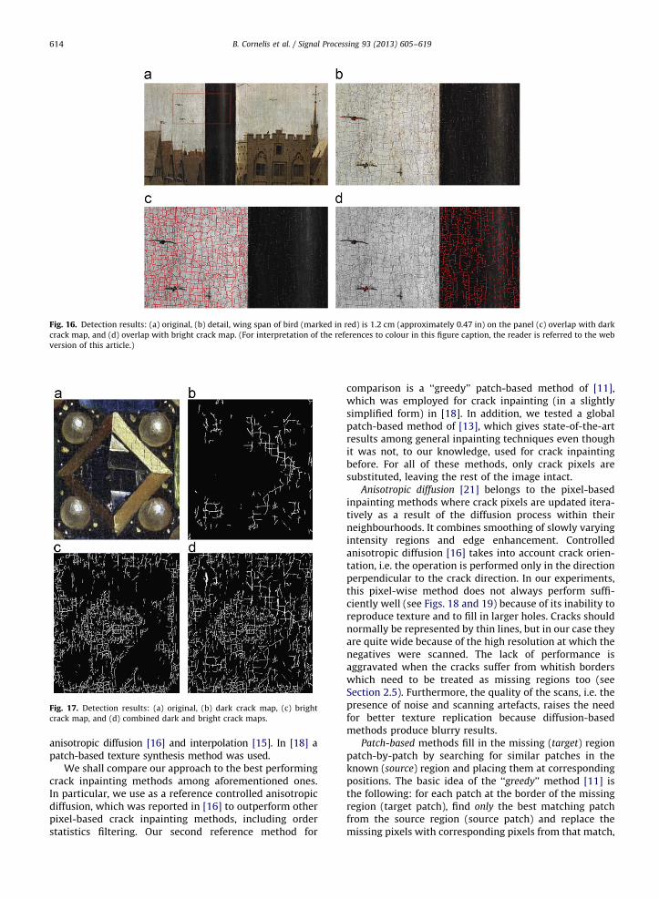
Fig. 16. Detection results: (a) original, (b) detail, wing span of bird (marked in red) is 1.2 cm (approximately 0.47 in) on the panel (c) overlap with dark
crack map, and (d) overlap with bright crack map. (For interpretation of the references to colour in this figure caption, the reader is referred to the web
version of this article.)
Fig. 17. Detection results: (a) original, (b) dark crack map, (c) bright
crack map, and (d) combined dark and bright crack maps.
B. Cornelis et al. / Signal Processing 93 (2013) 605–619614
anisotropic diffusion [16] and interpolation [15]. In [18] apatch-based texture synthesis method was used.
We shall compare our approach to the best performingcrack inpainting methods among aforementioned ones.In particular, we use as a reference controlled anisotropicdiffusion, which was reported in [16] to outperform otherpixel-based crack inpainting methods, including orderstatistics filtering. Our second reference method for
comparison is a ‘‘greedy’’ patch-based method of [11],which was employed for crack inpainting (in a slightlysimplified form) in [18]. In addition, we tested a globalpatch-based method of [13], which gives state-of-the-artresults among general inpainting techniques even thoughit was not, to our knowledge, used for crack inpaintingbefore. For all of these methods, only crack pixels aresubstituted, leaving the rest of the image intact.
Anisotropic diffusion [21] belongs to the pixel-basedinpainting methods where crack pixels are updated itera-tively as a result of the diffusion process within theirneighbourhoods. It combines smoothing of slowly varyingintensity regions and edge enhancement. Controlledanisotropic diffusion [16] takes into account crack orien-tation, i.e. the operation is performed only in the directionperpendicular to the crack direction. In our experiments,this pixel-wise method does not always perform suffi-ciently well (see Figs. 18 and 19) because of its inability toreproduce texture and to fill in larger holes. Cracks shouldnormally be represented by thin lines, but in our case theyare quite wide because of the high resolution at which thenegatives were scanned. The lack of performance isaggravated when the cracks suffer from whitish borderswhich need to be treated as missing regions too (seeSection 2.5). Furthermore, the quality of the scans, i.e. thepresence of noise and scanning artefacts, raises the needfor better texture replication because diffusion-basedmethods produce blurry results.
Patch-based methods fill in the missing (target) regionpatch-by-patch by searching for similar patches in theknown (source) region and placing them at correspondingpositions. The basic idea of the ‘‘greedy’’ method [11] isthe following: for each patch at the border of the missingregion (target patch), find only the best matching patchfrom the source region (source patch) and replace themissing pixels with corresponding pixels from that match,

Fig. 18. Inpainting results for the central part of Fig. 17(a): (a) original,
(b) with controlled anisotropic diffusion, (c) with ‘‘greedy’’ patch-based
method, and (d) with global patch-based method.
Fig. 19. Influence of bright borders on inpainting. Left: Dark crack map
as input. Right: Combined dark and bright crack map as input. First row
shows the original image overlapped with crack maps. Second and third
rows show inpainting results with controlled anisotropic diffusion and
the patch-based method, respectively.
Fig. 20. Schematic representation of a patch-based inpainting algorithm.
B. Cornelis et al. / Signal Processing 93 (2013) 605–619 615
until there are no more missing pixels (Fig. 20). Thematching criterion is usually the sum of squared differ-ences between the known pixels in the target patch andthe corresponding pixels in the source patch. In this way,both texture and structure are replicated. Preservingstructures is achieved by defining the filling order. Priorityshould be given to the target patches that contain objectboundaries and less missing pixels. In the case of digitizedpaintings, the object boundaries are usually difficult todetermine due to painting technique (incomplete brush-strokes), scanning artefacts, etc. Therefore, we definepriority based only on the relative number of existingpixels within the target patch.
The global patch-based method [13] poses inpaintingas a global optimization problem. For each target patch inthe missing region several candidate patches are foundbased on the known pixels and/or neighbouring context.Again, the target patches are visited in a certain order thatfavours patches containing object boundaries and lessmissing pixels. Then one of the candidates is chosen foreach position so that the whole set of patches (at allpositions) minimizes the global optimization function.
The performance of the aforementioned methods isevaluated only by visual inspection, as in other papers onthis application [16–18]. Quantitative comparison isinfeasible due to the unavailability of the ground truthdata, i.e. we have no information on how the paintinglooked like in its original state, before the deterioration ofwooden panels. On the other hand, the nature of thepainting itself and the influences of the acquisitionprocess of the digitized version (such as noise and
scanning artefacts) make it very difficult to replicate theproblem in a form of a suitable toy example on which theobjective measurements could be performed.

Fig. 21. Inpainting with patch-based methods on part of the book:
(a) original image, (b) method [11] with dark crack map, (c) method [11]
with combined dark and border crack map, (d) label constrained
method, k-means segmentation [1], (e) label constrained method, MRF
segmentation, fixed patch size, and (f) label constrained method, MRF
segmentation, adaptive patch size.
B. Cornelis et al. / Signal Processing 93 (2013) 605–619616
By visually comparing the results of these threemethods (see Fig. 18), we can see that both patch-basedmethods outperform the pixel-based one, due to theaforementioned reasons. However, they both still leavemuch room for improvement when crack inpainting isconsidered. The complex global method performs similarto the simpler greedy one, but it results in a very highcomputational load due to the high resolution of the scans(e.g. for an image of 660�700 pixels it is around 100times slower than the ‘‘greedy’’ method), making itimpractical for processing of larger areas. On the otherhand, limiting the method to small areas can jeopardizefinding the right match. Therefore, we adopt the ‘‘greedy’’patch-based method and improve it for crack inpainting.
3.2. Open problems and proposed solutions for crack
inpainting
To improve the inpainting performance, some specificsof the problem need to be tackled. In some cases thepresence of bright borders around the cracks (see begin-ning of Section 2) causes the missing crack regions to befilled with incorrect content and the positions of cracks toremain visible after inpainting (see the results on the leftof Fig. 19). Often, this problem is partially solved by usingthe bright crack map, which extends the dark crack mapwith the corresponding bright regions. Because this brightcrack map also marks some of the bright borders, thebenefit of using this map is evident in all cases: inthe results on the right of Fig. 19 more cracks are detectedand inpainted, causing a more pleasing visual appearance.However, for some images this procedure might not besufficient due to the width of the borders. In those cases,the inpainting preprocessing from Section 2.5 is used toobtain the map of crack border locations (see Fig. 15). Theimprovement of the inpainting result is shown in Fig. 21c,in comparison with the result obtained using just the darkcrack map shown in Fig. 21b. If the image also containsbright cracks, all three maps (dark crack map, bright crackmap and border crack map) are combined together.
The standard patch-based method gives reasonablygood visual results for most parts of the panels. However,the book of the Annunciation to Mary panel is exception-ally difficult to process due to the width of the cracks,prominent scanning artefacts and imperfect brushstrokes(see Fig. 4 for a detail and Fig. 24 for the whole book). Thiscauses some cracks to remain undetected and misguidesthe inpainting during the patch matching process. A firstconsequence is that we can get an inpainted image wheresmall parts of letters appear erroneously in the back-ground and the other way around, parts of letters get‘‘deleted’’, i.e. replaced by background. A second conse-quence is that positions of cracks remain visible. Exactlyin the part of the panel containing the book, accurateinpainting is very important because of the case study onpaleographical deciphering explained in Section 4. Tofurther improve the crack inpainting results, we introducea novel method that involves two contributions: anapproach to patch candidate selection and an approach topatch size adaptation. This method, that we call constrained
candidate selection, aims at performing context-aware
inpainting by constraining the search to certain parts ofthe image, depending on the content of the current targetpatch. Our method consists of three main steps:
1.
Exclusion of damaged pixels: Although we use the brightcrack map and/or border crack map (see earlier inSection 3.2) to deal with the problem of whitish bordersaround the cracks, some damaged pixels still remain.These pixels are either too distant from the crack, belongto the non-detected cracks or appear in the source regionnot related to the cracks. We detect these pixels based ontheir high values in the blue plane and we treat them asmissing ones. We do not use the patches from the sourceregion containing damaged pixels as possible matches.The threshold applied to the blue plane is chosen highenough to allow sufficient number of candidate sourcepatches, while still detecting the artefacts around cracks.In particular, we chose a fixed threshold equal to 220 byinspecting the histogram of manually marked damagedregions.
B. Cornelis et al. / Signal Processing 93 (2013) 605–619 617
2.
Fig(a)
refe
Label constrained matching: In the results from Fig. 21cit can be seen that patch-based inpainting occasionallyintroduces some artefacts. This can happen becausethe known part of the target patch is not distinctiveenough to find the right source patch. Another reasonis that undetected cracks can be present in the knownpart of the target patch so that the matched sourcepatch will probably contain a letter, since cracks andletters often have similar properties. To minimizethese errors we first segment the image into twoclasses: foreground (the letters and undetected cracks)and background (the page of the book). In [1], we usedthe k-means segmentation algorithm on the values ofthe red plane because the difference between the twoclasses is most visible there. Here, we improve theresults by using Markov Random Field (MRF) basedsegmentation [27], which is briefly explained below.Based on this segmentation, we constrain the searchfor candidate patches. When inpainting a part of thebackground, i.e. when all the known pixels in thetarget patch are labelled as background, we onlyaccept source patches that belong completely to thebackground as candidate patches. We could perform asimilar procedure for the target patches belongingcompletely to the foreground. However, some cracksthat remain undetected by using the detection meth-ods of Section 2 are also identified as foreground. Thiscan result in the unjustified insertion of letters and/orcracks (foreground) in the background. Therefore, ifthe target patch is not entirely in the background, wesearch through all possible candidates.
3.
Adaptive patch size: Instead of using a fixed patch size,as most inpainting methods do, we make the patchsize adaptive to the local context. We start from themaximal patch size and check if the target patchcompletely belongs to the background. If this is thecase, we constrain the search to the background, as inthe previous step. If not, we reduce the patch size byhalf and repeat the same procedure. Finally, if eventhis smaller patch only partially belongs to the. 22. Segmentation results for part of the book (cracks detected as in Section 2
result of k-means [1] and (b) result of MRF based segmentation. (For interpret
rred to the web version of this article.)
background, we search for the match of the targetpatch of the maximal size at all possible locations.
As can be seen in Fig. 22a, k-means (as used in [1])yields a noisy segmentation result with a lot of misclassi-fied isolated dots in the background. Better context aware-ness would be beneficial to circumvent the incompletenessof letters. For these reasons, we use MRF based segmenta-tion. To define the MRF, we need to specify local evidence,i.e. the relationship between the measured (pixel) valueand the segment label, and a pairwise potential function, i.e.the dependency between two neighbouring segment labels(see [27] for more details). The former is defined as theGaussian function with mean value equal to the value ofthe cluster center obtained with the k-means algorithm,and standard deviation computed within each cluster. Thepairwise potential is determined by the discontinuitypreserving Potts model Vi,jðxi,xjÞ ¼ KTðxiaxjÞ, where T isone if its argument is true and zero otherwise, K is apositive constant and xi and xj are neighbouring segmentlabels. For inference, i.e. to find the maximum a posterioriestimate of the global optimization function, we use themethod from [28] previously developed by some of theauthors of this paper. The segmentation yielded by thismethod is shown in Fig. 22b, and we can see that theisolated dots have been removed and that the letters aremore compact.
Fig. 21d contains the result of the constrained candi-date selection from [1] that uses k-means segmentation.The effects of the proposed constrained candidate selec-tion, using the MRF based segmentation, are illustrated inFig. 21e for the constant patch size, and in Fig. 21f for theadaptive patch size. The results in Fig. 21e and f areperceptually better than those in Fig. 21d. Compared toFig. 21e, Fig. 21f has less artefacts in the backgroundmeaning that the adaptive patch size approach can betterlocate target and source patches belonging to the back-ground. Also, some letters are better inpainted. In com-parison with the results of the method from [11] in
in red, letters and undetected cracks in black, background in white):
ation of the references to colour in this figure caption, the reader is

Fig. 23. Label constrained matching for image containing four seg-
ments: (a) original, (b) MRF segmentation, (c) result of patch-based
method [11], and (d) result with label constrained matching. Fig. 24. Book in the panel of the Annunciation to Mary. Its actual size on
the panel is approximately 12 cm (or 4.7 in) in length and a page is
approximately 7 cm (2.8 in) wide.
B. Cornelis et al. / Signal Processing 93 (2013) 605–619618
Fig. 21c, the letters are better inpainted and the wholeimage contains less visually disturbing bright borders.
Note that our label constrained matching, i.e. thesecond step of the complete method, can in principle alsobe used on more complex images, containing more thantwo segments, to limit the search to specific areas so thatthe computation time is reduced. However, in general, theimprovement on the quality of the inpainting result isminimal. Results are shown in Fig. 23: (c) shows resultswithout label constrained matching and (d) with labelconstrained matching, based on the segmentation shownin (b).
4. A case study—De Visione Dei
In this section we focus on a detail that has puzzled arthistorians for years, namely the text in a book representedon the panel of the Annunciation to Mary (see Fig. 24).The text can only be studied from high resolution photo-graphs as access to the altarpiece (which is being keptinside a vault behind glass) is difficult. Furthermore, theheight at which the text is situated on the panel makes adirect reading for paleographers impossible. The text inthe Virgin Annunciate’s book is written in a so-calledlittera formata (see Fig. 4 for a detail), which always posesdifficulties for paleographers to decipher. Sequences ofvertical stripes, often without ligatures, as e.g. 9999, can beread as combinations of i, u, n, m, v, w, etc. Moreover,horizontal abbreviation marks above the text lines replace
letters ‘n’ or ‘m’. In this particular text, the crack patternmade deciphering even more problematic. Therefore, onlytwo significant word groups have been read: de visione dei
(on the vision of God), and dicit sapiens: ut possim edificare
(says the wise man: that I may build) [29]. This providesnot enough information to identify the text; it allows onlyto speculate that it could be one of the numerousmedieval commentaries on the Bible.
As amply demonstrated in the abundant art historicalliterature on the Ghent Altarpiece, each one of the manyinscriptions or texts on this painting bares importantclues to the original complex iconographical and theolo-gical meaning of this work of art. Therefore any attemptto improve the legibility of the text next to the VirginAnnunciate is of great relevance to its art historicalinterpretation.
The crack detection and inpainting process describedabove has yielded a better legibility indeed. Although thetext cannot be read entirely, some additional word groupscan be deciphered now as: hio dicta significata (telling themessage with mouth wide open), de virtutibus d[ei]
(on the virtues of God), in videndo (the appearance ofGod). The former reading of Prologus iste est ad can becompleted with the words differentiam cognite dei. More-over, the paragraph mark on the upper left of the pageshould be read as LXII (62) rather than VII (7).
All deciphered text fragments are related to theAnnunciation, and can be found in Thomas of Aquino’s
B. Cornelis et al. / Signal Processing 93 (2013) 605–619 619
Summa Theologica (written between 1266 and 1273). Thisprominent medieval theologian commented in his bookon the Annunciation, on the vision of God, and in the 62ndparagraph of the Summa, on the cardinal and theologicalvirtues (virtutibus). These first results provide a basis forfurther research into the iconographical implications ofthis text.
5. Conclusions
In this paper, we introduce a novel way of virtuallyrestoring paintings by detecting and removing cracks.The practicability of the proposed methods is demon-strated on images taken from the Ghent Altarpiece. Due tothe heterogeneous nature of these images, existing solu-tions found in the literature have proven to be insuffi-cient. For the detection of cracks, the outputs of three newdetection schemes are combined, hence capitalizing oneach method’s strength as much as possible. The paperdescribes in detail all problems encountered and proposessolutions for each of them. Due to the complexity of theproblem to separate the semantic content of the paintingfrom the crack pattern, several case dependent para-meters have to be introduced, either automatically deter-mined or manually tuned. For each of them we describehow the values can be found and we motivate the choicesmade. Furthermore, we explored the use of patch-basedinpainting for the removal of the detected cracks andhighlighted specific issues when inpainting the GhentAltarpiece. Improvements to existing patch-basedinpainting are proposed and we demonstrate the gainedperformance. The inpainted images show less artefactsand the results are overall visually more pleasing. Todemonstrate the applicability and the use of the proposedtechniques, we presented the initial findings of a casestudy involving the deciphering of text in the panel of theAnnunciation to Mary.
Acknowledgements
The Van Eyck images are based on photographicnegatives (b45, b24. g09, 39-19) from the Dierickfondsmade available to the Ghent University by the family ofthe late Alfons Dierick. We thank Saint Bavo cathedral,Lukas Art in Flanders and the Dierickfonds for permissionto use these materials in this research article.
References
[1] T. Ruzic, B. Cornelis, L. Platisa, A. Pizurica, A. Dooms, W. Philips, M.Martens, M. De Mey, I. Daubechies, Virtual restoration of the GhentAltarpiece using crack detection and inpainting, in: AdvancedConcepts for Intelligent Vision Systems (ACIVS 2011), Ghent,Belgium.
[2] J. Mohen, M. Menu, B. Mottin, Mona Lisa: Inside the Painting, HarryN. Abrams, New York, NY, USA, 2006.
[3] F.S. Abas, K. Martinez, Classification of painting cracks for content-based analysis, in: IS&T/SPIEs 15th Annual Symposium on
Electronic Imaging 2003: Machine Vision Applications in IndustrialInspection XI, 2003.
[4] S. Bucklow, The description of craquelure patterns, Studies inConservation 42 (1997).
[5] F.S. Abas, Analysis of Craquelure Patterns for Content-Based Retrieval,Ph.D. Thesis, University of Southampton, 2004.
[6] S. Bucklow, A stylometric analysis of craquelure, Computers andHumanities 31 (1998).
[7] A.M. Lopez, F. Lumbreras, J. Serrat, J.J. Villanueva, Evaluation ofmethods for ridge and valley detection, IEEE Transactions onPattern and Machine Intelligence 21 (1999) 327–335.
[8] F. Zana, J.C. Klein, Segmentation of vessel-like patterns usingmathematical morphology and curvature evaluation, IEEE Transac-tions on Image Processing 10 (2001) 1010–1019.
[9] M. Bertalmio, G. Sapiro, V. Caselles, C. Ballester, Image inpainting,in: SIGGRAPH, New Orleans, USA, 2000.
[10] T.F. Chan, J. Shen, Non-texture inpainting by curvature-drivendiffusions (cdd), Journal of Visual Communication and ImageRepresentation 12 (2001) 436–449.
[11] A. Criminisi, P. Perez, K. Toyama, Region filling and object removalby exemplar-based image inpainting, IEEE Transactions on ImageProcessing 13 (2004) 1200–1212.
[12] J. Sun, L. Yuan, J. Jia, H.-Y. Shum, Image completion with structurepropagation, ACM Transactions on Graphics 24 (2005) 861–868.
[13] N. Komodakis, G. Tziritas, Image completion using efficient beliefpropagation via priority scheduling and dynamic pruning, IEEETransactions on Image Processing 16 (2007) 2649–2661.
[14] Z. Xu, J. Sun, Image inpainting by patch propagation using patchsparsity, IEEE Transactions on Image Processing 19 (2010)1153–1165.
[15] M. Barni, F. Bartolini, V. Cappellini, Image processing for virtualrestoration of artworks, IEEE Multimedia 7 (2000) 34–37.
[16] I. Giakoumis, N. Nikolaidis, I. Pitas, Digital image processingtechniques for the detection and removal of cracks in digitizedpaintings, IEEE Transactions on Image Processing 15 (2006)178–188.
[17] S.V. Solanki, A.R. Mahajan, Cracks inspection and interpolation indigitized artistic picture using image processing approach, Inter-national Journal of Recent Trends in Engineering (IJRTE) 1 (2009)97–99.
[18] G.S. Spagnolo, F. Somma, Virtual restoration of cracks in digitizedimage of paintings, Journal of Physics: Conference Series 249(2010) 012059.
[19] I. Giakoumis, I. Pitas, Digital restoration of painting cracks, in:ISCAS 98, Proceedings of the IEEE International Symposium onCircuits and Signals, 1998, pp. 269–272.
[20] K. Zuiderveld, Contrast Limited Adaptive Histogram Equalization,Academic Press Professional, Inc., San Diego, CA, USA, 1994,pp. 474–485.
[21] P. Perona, J. Malik, Scale-space and edge detection using anisotropicdiffusion, IEEE Transactions on Pattern Analysis and MachineIntelligence 12 (1990) 629–639.
[22] R. Poli, G. Valli, An algorithm for real-time vessel enhancement anddetection, Computer Methods and Programs in Biomedicine 52(1997) 1–22.
[23] F. Meyer, Cytologie quantitative et morphologie mathematique,Ph.D. Thesis, Ecole des Mines, 1979.
[24] N. Otsu, A threshold selection method from Gray-level Histograms,IEEE Transactions on Systems, Man and Cybernetics 9 (1979) 62–66.
[25] M. Elad, M. Aharon, A. Bruckstein, The k-svd: an algorithm fordesigning of overcomplete dictionaries for sparse representation,IEEE Transactions on Signal Processing 54 (2006) 4311–4322.
[26] L. Lam, S. Lee, C. Suen, Thinning methodologies—a comprehensivesurvey, IEEE Transactions on Pattern Analysis and Machine Intelli-gence 14 (1992) 869–885.
[27] S.Z. Li, Markov Random Field Modeling in Computer Vision,Springer-Verlag, 1995.
[28] T. Ruzic, A. Pizurica, W. Philips, Neighbourhood-consensus messagepassing and its potentials in image processing applications, in: SPIEElectronic Imaging, 2011.
[29] J.D. Baets, De gewijde teksten van het lam gods kritisch onderzocht,Verslagen en Mededelingen van de Koninklijke Academie voorTaal-en Letterkunde (1961) 560–561.