Embed Size (px)
Citation preview
Operating Instructions
Boiler controller Lambdatronic S 3200 - TouchVersion 50.04 - Build 05.09 | Version 60.01 - Build 01.23
Translation of the original German operating instructions for technicians and operatorsRead and follow the instructions and safety information!
Technical changes, typographical errors and omissions reserved!B0840314_en | Edition 21/07/2014
Froling GesmbH | A-4710 Grieskirchen, Industriestraße 12 | www.froeling.com

Table of Contents
1 General 51.1 About these instructions 51.2 Safety information 5
2 Electrical connection and wiring 62.1 Core module and connection options 62.1.1 Board view 6 Connection instructions 72.1.2 Mains connection 82.1.3 Connecting the flue gas sensor 82.1.4 Combination with oil burner 92.1.5 Valve for flue gas condenser connection 92.1.6 Connecting the remote control 102.1.7 Connecting a high efficiency pump to the core module 112.2 Expansion modules 122.2.1 Heating circuit module 122.2.2 Hydraulic module 13 Connecting an isolating valve 14 Connecting a high efficiency pump to the hydraulic module 152.2.3 Return mixer module 162.2.4 Ignition expansion 182.2.5 Connecting the bus cable 182.2.6 Connect the patch cable to the bus plug 192.2.7 Setting end jumpers 192.2.8 Setting the module address 202.3 Connection diagrams according to pump types 20
3 Overview of the basic functions 223.1 Visual display 223.1.1 Status LED 223.1.2 Control icons 233.1.3 Display icons 243.2 Operating statuses 253.3 Updating the software of the touch control 263.4 Calibrating the touchscreen 28
4 Operation 304.1 Before switching on for the first time 304.1.1 Controller check 304.1.2 Check on the connected units 304.1.3 System Check 304.2 Navigation within the info menu 314.3 Navigation within the system menu 314.3.1 Navigating the menus 324.4 Adjusting parameters 344.5 Setting times 354.6 Setting the date/time 37
Table of Contents
2 Froling GesmbH | A-4710 Grieskirchen, Industriestraße 12 | www.froeling.com

4.7 Quick menu 384.7.1 "Operating level” function 384.7.2 "Choose language” function 384.7.3 "Chimney sweep” function 384.7.4 "Extra heating” function 384.7.5 “Mode in automatic mode” function 384.7.6 "Extra loading” function 384.7.7 “Ignition” function 384.7.8 "Touch cleaning” function 384.8 Initial startup 394.8.1 Switching user level 394.8.2 Setting the system selection 40 Open the system selection menu 40 Selecting the boiler type 41 System selection 43 DHW tank system 44 Heating system 45 Solar system 45 Boiler remote control 464.8.3 Before heating up for the first time 46 Drives 46
5 Menu overview and parameters 475.1 Menu - Heating 475.1.1 Status displays for the heating circuits 485.1.2 Temperature settings for the heating circuits 495.1.3 Heating times of the heating circuits 505.1.4 Service parameters of the heating circuits 505.1.5 Service parameters for heating up program 51 Heating up programs 535.1.6 General Settings 545.2 Menu - Water 545.2.1 Status displays for the DHW tank 555.2.2 Temperature settings of the DHW tank 555.2.3 Heating times of the DHW tank 565.2.4 Service parameters of the DHW tank 565.3 Menu - Solar 575.3.1 Status displays for the solar system 585.3.2 Temperature settings for the solar system 595.3.3 Service parameters of the solar system 605.3.4 Solar heat meter 625.4 Menu - Storage tank 635.4.1 Status displays of the storage tank 645.4.2 Temperature settings for the storage tank 645.4.3 Service parameters of the storage tank 655.5 Menu - Boiler 665.5.1 Status displays for the boiler 675.5.2 Temperature settings for the boiler 675.5.3 Service parameters of the boiler 685.5.4 General Settings 68 Operator data 69
5.6 Menu - Boiler 2 695.6.1 Status displays for the backup boiler 705.6.2 Temperature settings for the backup boiler 70
Table of Contents
Operating Instructions Lambdatronic S 3200 - Touch | B0840314_en 3

5.6.3 Service parameters of the backup boiler 715.7 Menu - Ignition 725.8 Menu - Network pump 745.8.1 Network pump status displays 755.8.2 Network pump temperature settings 755.8.3 Service parameters for the network pump 765.9 Menu - Difference regulator 775.9.1 Status displays for the difference regulator 785.9.2 Temperature settings for the difference regulator 785.9.3 Service parameters for the difference regulator 795.10 Menu - Circulation pump 795.10.1 Status displays for the circulation pump 805.10.2 Temperature settings for the circulation pump 805.10.3 Time settings for the circulation pump 815.10.4 Service parameters of the circulation pump 815.11 Menu - Manual 825.11.1 Digital outputs 835.11.2 Analogue outputs 835.11.3 Digital inputs 845.12 Menu - System 845.12.1 Setting 85 Adjustable parameters: Boiler temperature 85 Adjustable Parameters: Flue Gas 86 Adjustable parameters - Ignition 87 Adjustable Parameters: Air settings 88 Adjustable parameters: Lambda values 89 Adjustable parameters: Lambda values - LSM11 Lambda probe 89 Adjustable parameters: Lambda values – Broadband probe 90 Adjustable parameters: General settings 925.12.2 Current values 935.12.3 Sensors and pumps 945.12.4 Display operating rights 95 Froeling Connect 965.12.5 Display allocation 965.12.6 System selection 975.13 Menu - Diagnostics 975.13.1 Error display 985.13.2 Error history 985.13.3 Clear error history 995.14 Menu - Display settings 995.14.1 General 100 Network settings 1015.14.2 Date / Time 1015.14.3 Software update / Service 1025.15 PWM / 0 - 10V settings 102
6 Troubleshooting 1046.1 Procedure for fault messages 104
7 Setting protocol 106
Table of Contents
4 Froling GesmbH | A-4710 Grieskirchen, Industriestraße 12 | www.froeling.com

1 General
1.1 About these instructionsPlease read and follow the operating instructions, in particular the safety informationcontained therein. Keep them available next to the boiler.These operating instructions contain important information about operation, electricalconnection and troubleshooting for the Lambdatronic S 3200 control.
NOTICE
The values given in the parameter lists are examples, and should not be used as standard values!
The constant further development of our products means that there may be minor dif‐ferences from the pictures and content. If you discover any errors, please let us know.
1.2 Safety information
DANGER
When working on electrical components:
Risk of electrocution!
When work is carried out on electrical components:❒ Only have work carried out by a qualified electrician❒ Observe the applicable standards and regulations
➥ Work must not be carried out on electrical components by unauthorisedpeople
WARNING
When touching hot surfaces:
Severe burns are possible on hot surfaces and the flue gas pipe!
When work is carried out on the boiler:❒ Shut down the boiler in a controlled way (operating status "Off") and allow it to
cool down❒ Protective gloves must generally be worn for work on the boiler, and it should
only be operated using the handles provided❒ Insulate the flue pipes or simply avoid touching them during operation.
The information on safety, standards and guidelines in assembly and operating in‐structions for the boiler should also be observed.
General 1About these instructions
Operating Instructions Lambdatronic S 3200 - Touch | B0840314_en 5

2 Electrical connection and wiring
2.1 Core module and connection options
2.1.1 Board view
2 Electrical connection and wiringCore module and connection options
6 Froling GesmbH | A-4710 Grieskirchen, Industriestraße 12 | www.froeling.com
Connection instructions
Port Cable dimensions / Specifications / Information
Bus (1) Port with cable – LIYCY paired 2x2x0.5;⇨ See "Connecting the bus cable" [page 18]❒ Warning! CAN L and CAN H must not be connected to +UBUS!
Bus (2) Patch cable CAT 5 RJ45 SFTP 1:1 configuration
Bus (3) Patch cable CAT 5 RJ45 SFTP 1:1 configuration, boiler display port
COM 2 (4) Null modem cable 9-pin SUB-D;❒ Port can be used as a MODBUS interface
General Settings
COM 1 (5) Null modem cable 9-pin SUB-D;❒ Service interface for installing new boiler software or port for the visualisation
software
Broadband probe (6) Connection cable1) 5 x 0.75 mm2
❒ Connection of a BOSCH or NTK broadband Lambda probe
Secondary air (7) Connection cable1) 5 x 0.75 mm²❒ When using the S1 Turbo firewood boiler, the air flap must be connected a the
“Secondary air” connection port
Primary air (8) Connection cable1) 5 x 0.75 mm²
Latch (9) Connection cable1) 2 x 0.75 mm2
High-limit thermostat - STL (10)
EMERGENCY STOP (11) Connection cable1) 2 x 0.75 mm2
❒ Warning! Do not connect the emergency off/emergency stop switch to the powersupply cable of the boiler. The switch must be a N/C switch and it must be linkedto the 24V safety chain of the STL at this terminal.
Flowmeter FLM (12) Connection cable1) 2 x 0.75 mm2
Lambda probe (13) Connection cable1) 4 x 0.75 mm²❒ LSM11 Lambda probe connection
Boiler release (14) Connection cable1) 2 x 0.75 mm2
❒ Warning! The connection must be a floating connection.
Flue gas temperature sensor (15) Connection cable1) 3 x 0.75 mm2
Door switch DCS (16) Connection cable1) 2 x 0.75 mm2
Sensor 2/1 (17/18) Connection cable1) 2 x 0.75 mm2
Outside temperature sensor (19) Connection cable1) 2 x 0.75 mm2,shielded from 25m cable length
Room temperature sensor 2/1(20/21)
Flow temperature sensor 2/1(22/23)
Return sensor RTS (24) Connection cable1) 2 x 0.75 mm2
Boiler sensor BS (25)
PDM / 0-10V Pump 1 (26)
Induced draught (27) Connection cable1) 3 x 1.5 mm2, power supplyConnection cable1) 3 x 0.75 mm2, analysis of current speed
Electrical connection and wiring 2Core module and connection options
Operating Instructions Lambdatronic S 3200 - Touch | B0840314_en 7

Port Cable dimensions / Specifications / Information
Pump 1 on core module (28) Connection cable1) 3 x 1.5 mm2, max. 1.5A / 280W / 230V
Mains (29) Connection cable 1) 3 x 1.5 mm2; fused with 16A (provided by the customer)
Mixing valve 2/1 (30/31) Connection cable1) 4 x 0.75 mm2, max. 0.15A / 230V
Heating circuit pump 2/1 (32/33) Connection cable1) 3 x 1.5 mm2, max. 2.5A / 500W
Heating circuit pump HCP 0 / burn‐er relay (34)
Connection cable1) 3 x 1.5 mm2, max. 3A / 600VA
(35) Connection cable1) 2 x 0.75mm2
⇨ See "Valve for flue gas condenser connection" [page 9]1.YMM as per ÖVE-K41-5 or H05VV-F as per DIN VDE 0881-5
2.1.2 Mains connectionConnect the power supply at the "Mains connection" plug❒ Flexible sheathed cable must be used for the wiring; this must be of the correct
size to comply with applicable regional standards and regulations.❒ The power supply line (mains connection) must be fitted with a 16A fuse by the
customer. If a safety overload switch is used it should be a type with 16A.
2.1.3 Connecting the flue gas sensor
green-yellow
red +
blue -
Core module
2 Electrical connection and wiringCore module and connection options
8 Froling GesmbH | A-4710 Grieskirchen, Industriestraße 12 | www.froeling.com

2.1.4 Combination with oil burnerThe connection "Heating circuit pump 0" can be used for heating circuit pump 0 or asburner relays depending on the system setting. Connecting a HCP 0 up to max. 2 Ampere:
Core module
L1
N
HCP0
Connecting a HCP 0 up to max. 5 Ampere:
Connection as burner relays:
Core module
L1
N
To oil boiler control:
floating contact for burner
release
2.1.5 Valve for flue gas condenser connection
Electrical connection and wiring 2Core module and connection options
Operating Instructions Lambdatronic S 3200 - Touch | B0840314_en 9

2.1.6 Connecting the remote controlA room temperature sensor is included in the remote control, which sends the currentroom temperature to the control.
affecting room:
AUS
UHR
NACHT
TAG
FV
RFFV
COM
Raumfühler FRA
RF 1/2
Kernmodul S/P/H 3200
not affecting room:
AUS
UHR
NACHT
TAG
FV
RFFV
COM
Raumfühler FRA
RF 1/2
Kernmodul S/P/H 3200
Switch settings:
Switched-off Heating circuit deactivated, only frost protec‐tion!
Automatic mode Heating phases according to setback program
Setback mode Ignores the heating phases
Override circuit Ignores the setback
Handwheel… Allows you to adjust the temperature by +/- 3°C
IMPORTANT! See assembly instructions/functional description for room temperaturesensor FRA
2 Electrical connection and wiringCore module and connection options
10 Froling GesmbH | A-4710 Grieskirchen, Industriestraße 12 | www.froeling.com

2.1.7 Connecting a high efficiency pump to the core moduleWire the high efficiency pump as shown in the connection diagram below:
KERNMODUL
FRKEM25
PDM / 0-10V (+)PDM / 0-10V ( )
Pump 1 (L)
Pump 1 ( )
Pump 1 (N)
❒ Connect the power supply for the high efficiency pump to output "Pump 1" of thecore module
❒ Connect the PWM cable of the high efficiency pump to the corresponding port“PWM / 0-10V"➥ Make sure that the cables are configured correctly (polarity) in accordance with
the connection diagram of the pump! Important! When using a Froling pump assembly:⇨ See "Connection diagrams according to pump types" [page 20]
Electrical connection and wiring 2Core module and connection options
Operating Instructions Lambdatronic S 3200 - Touch | B0840314_en 11
2.2 Expansion modules
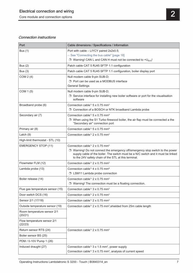
2.2.1 Heating circuit moduleTwo heating circuits can be controlled as standard with the core module. The heating circuit module boards must be used to expand the heating circuit control.Eight heating circuit modules (addresses 0 to 7) can be added, and the module ad‐dress must be set correctly.⇨ See "Setting the module address" [page 20]
Connection instructions
Port Cable dimensions / Specifications / Information
Bus (1) Port with cable – LIYCY paired 2x2x0.5;⇨ See "Connecting the bus cable" [page 18]❒ Warning! CAN L and CAN H must not be connected to +UBUS!
Flow temperaturesensor 1/2 (2)
Connection cable1) 2 x 0.75mm2
Room temperaturesensor 1/2 (3)
Connection cable1) 2 x 0.75mm2, shielded from 25m cable length
Mains (4) Connection cable1) 3 x 1.5mm2, fuse 10A
Heating circuitpump 1/2 (5)
Connection cable1) 3 x 1.5mm2, max. 2.5A / 230V / 500W
Mixing valve 1/2 (6) Connection cable1) 4 x 0.75mm2, max. 0.15A / 230V1.YMM as per ÖVE-K41-5 or H05VV-F as per DIN VDE 0881-5
2 Electrical connection and wiringExpansion modules
12 Froling GesmbH | A-4710 Grieskirchen, Industriestraße 12 | www.froeling.com

2.2.2 Hydraulic moduleThe hydraulic module makes the connections of sensors and pumps available for thehydraulic components of the system (storage tank, DHW tank etc.).A hydraulic module is included in the delivery as standard (address 0). A further sevenmodules (addresses 1 to 7) can be retrofitted.You must ensure that the module address is given correctly.⇨ See "Setting the module address" [page 20]
AO
-P
1
AO
-P
2
6,3AT
Hydraulikmodul(FRHYU 21)
Bu
s (
2)
Fü
hle
r 1
(3
)
Fü
hle
r 5
(7
)
Ne
tz (
9)
Pu
mp
e 2
(11
)
Fü
hle
r 2
(4
)
Fü
hle
r 4
(6
)
Fü
hle
r 3
(5
)
Pu
mp
e 1
(1
0)
Fü
hle
r 6
(8
)
Bu
s(2
)
2x B
us
(1)
Modul-Adresse
End-Jumper
Netzsicherung
CA
N L
CA
N H
+U
Bus
N L N L N L
+ +
Connection instructions
Port Cable dimensions / Specifications / Information
2 x Bus (1) Patch cable CAT 5 RJ45 SFTP 1:1 configuration
Bus (2) Connection with cable - LIYCY paired 2x2x0.5;⇨ See "Connecting the bus cable" [page 18]❒ Important! CAN L and CAN H must not be connected to +UBUS !
Sensors 1 – 6 (3-8) Connection cable1) 2 x 0.75mm2, shielded from 25m cable length
Mains (9) Connection cable1) 3 x 1.5mm2, fuse 10A
Pump 1/2 (10/11) Connection cable1) 3 x 1.5mm2, max. 1.5A / 230V / 280W1.YMM as per ÖVE-K41-5 or H05VV-F as per DIN VDE 0881-5
Electrical connection and wiring 2Expansion modules
Operating Instructions Lambdatronic S 3200 - Touch | B0840314_en 13

Connecting an isolating valveIf an isolating valve is connected to a speed-controlled pump outlet, an RC elementmust be used.Furthermore, the minimum speed for the pump outlet in use must be set to 100% inthe boiler control system.
Connection example:
The outer cable L(bn) should be connected to the outer cable of the respective mainssupply of the module or to the core module, HCP0/burner relay output at pin “LV”.
2 Electrical connection and wiringExpansion modules
14 Froling GesmbH | A-4710 Grieskirchen, Industriestraße 12 | www.froeling.com

Connecting a high efficiency pump to the hydraulic moduleWire the high efficiency pump as shown in the connection diagram below:
❒ Connect the power supply for the high efficiency pump to output "Pump 1" or"Pump 2" of the hydraulic module
❒ Connect the PWM cables of the high efficiency pump to the corresponding port"AO-P1" or "AO-P2"➥ Make sure that the cables are configured correctly (polarity) in accordance with
the connection diagram of the pump! IMPORTANT! When using a Froling pump assembly:⇨ See "Connection diagrams according to pump types" [page 20]
Electrical connection and wiring 2Expansion modules
Operating Instructions Lambdatronic S 3200 - Touch | B0840314_en 15

2.2.3 Return mixer moduleThe return mixer module provides the connection for a return mixer. The relevant sen‐sor is the return sensor on the core module. If this module is used, the “Returnflow mixer through external module” parameter must be set to “YES”.Setting the system type
Connection instructions
Port Cable dimensions / Specifications / Information
Bus (1) Connection with enclosed patch cable 0.5m
2 x mains (2) Connection cable1) 3 x 1.5mm2,
Return mixer (3) Connection cable1) 4 x 0.75mm2, max. 0.15A / 230V1.YMM as per ÖVE-K41-5 or H05VV-F as per DIN VDE 0881-5
Connection example
2 Electrical connection and wiringExpansion modules
16 Froling GesmbH | A-4710 Grieskirchen, Industriestraße 12 | www.froeling.com

Connection diagram
Hydraulic module(FRHYU 14)
Core module(FRKEM 22)
Retu
rn m
ixer
mo
du
le(F
RR
LA
10
)
Main switchPlug
Mains
Connect return mixermodule and hydraulicmodule with bus cable
Use delivered mainscable for connectionto terminal block.
Ignition module(optional)
Return mixer
Return sensor
Electrical connection and wiring 2Expansion modules
Operating Instructions Lambdatronic S 3200 - Touch | B0840314_en 17

2.2.4 Ignition expansion
The ignition expansion makes the con‐nection for an electrical ignition fan avail‐able and makes it possible for the boilerto be heated up automatically.
Connection diagram
2.2.5 Connecting the bus cableFor the bus connections between the individual modules, cable type LIYCY paired 2x2x0.5 should be used. The connection to the 5-pin plugs should becarried out according to the following diagram:
+UBUS
CAN H
CAN L
+UBUS
CAN H
CAN L
Braided shield
White
Green
Yellow
Brown
Braided shield
White
Green
Yellow
Brown
2 Electrical connection and wiringExpansion modules
18 Froling GesmbH | A-4710 Grieskirchen, Industriestraße 12 | www.froeling.com

2.2.6 Connect the patch cable to the bus plugTo connect a patch cable to a RJ45 bushing and a 5-pin plug, follow the connectiondiagram below:
2.2.7 Setting end jumpersTo ensure smooth running of the bus system, the jumper must be placed on the lastmodule.
End jumper not set End jumper set
If the contacts at the base of the end jumper are not bridged (image left), it is referredto as “not set". In this case there is no bus termination. If the contacts are closed (im‐age right), the end jumper is set and the bus connection is terminated.
Electrical connection and wiring 2Expansion modules
Operating Instructions Lambdatronic S 3200 - Touch | B0840314_en 19

2.2.8 Setting the module addressFor hydraulic modules or heating circuit modules it is necessary to set the required or‐der with the module addresses. The first board of a module type should always havethe address 0, so that the standard hydraulic systems set do not have to be subse‐quently configured. For further module types ascending module addresses (address 1- 7) are set.A hydraulic module with address 0 is included in standard delivery. If a second hy‐draulic module is also installed, address 1 is set.
Module address set
Heating circuit mod‐ule
Hydraulic module
Heating circuit Sensor Pump
0 03 – 04 0.1 – 0.6 0.1 – 0.2
1 05 – 06 1.1 – 1.6 1.1 – 1.2
2 07 – 08 2.1 – 2.6 2.1 – 2.2
3 09 – 10 3.1 – 3.6 3.1 – 3.2
4 11 – 12 4.1 – 4.6 4.1 – 4.2
5 13 – 14 5.1 – 5.6 5.1 – 5.2
6 15 – 16 6.1 – 6.6 6.1 – 6.2
7 17 - 18 7.1 – 7.7 7.1 – 7.2
2 Electrical connection and wiringExpansion modules
20 Froling GesmbH | A-4710 Grieskirchen, Industriestraße 12 | www.froeling.com

2.3 Connection diagrams according to pump types
Three different pump types are used in all depending on the pump assembly used:
WILO Stratos Para WILO Stratos TEC WILO Yonos Para
Either a 2-pin control cable (WILO Stratos TEC, WILO Yonos Para) or a 4-pin controlcable (WILO Stratos Para) is used for the connection depending on the pump type.Please follow the connection instructions below for the wiring depending on the pumptype used:
Pump type with 2-pin control cable
Power supply 2-pin control cable
(brown) L
(blue) N
(yellow-green) PE
Wire the power supply to the pumpoutlet on the board
Connect the control cable to the board’s PWM output,making sure that the polarity is correct:- blue wire to earth- brown wire to plus
Pump type with 4-pin control cable
Power supply 4-pin control cable
(brown) L
(blue) N
(yellow-green) PE
Wire the power supply to the pumpoutlet on the board
Connect the control cable to the board’s PWM output,making sure that the polarity is correct:- brown wire to earth- white wire to plusDo not use the other two wires (blue, black) and insu‐late if necessary
Electrical connection and wiring 2Connection diagrams according to pump types
Operating Instructions Lambdatronic S 3200 - Touch | B0840314_en 21

3 Overview of the basic functions
3.1 Visual display
A
C D E
F
B
G
H
I
A Date and time display
B Image of set boiler type
C Info menu icon for viewing all system information
D System menu icon for opening the system settings. All parameters can be displayed/edited depending on the user level
E Quick menu icon for viewing the available quick functions
F Mode icon
G Status LED for displaying the current operating status
H Brightness sensor for automatically adjusting the display brightness
I USB port for connecting a USB stick for software updates
3.1.1 Status LEDThe status LED shows the operating status of the system:▪ GREEN flashing (interval: 5 sec OFF, 1 sec ON): Off▪ GREEN constant: BOILER SWITCHED ON▪ ORANGE flashing: WARNING▪ RED flashing: FAULT
3 Overview of the basic functionsVisual display
22 Froling GesmbH | A-4710 Grieskirchen, Industriestraße 12 | www.froeling.com

3.1.2 Control icons
Cancel icon
Discards any values entered without saving and closes messages.
Confirm icon
Confirms any values entered and activates parameters.
Home icon
Tapping the Home icon takes you back to the basic display from any menu.
Info menu icon
To access all system information. The information is ordered in a circular buffer. Theright and left arrows are used to switch between the individual pages.
Quick menu icon
Opens the quick menu. Various functions are available depending on the user level,system configuration and current status.
Pen icon
If a parameter has the pen symbol beside it, it means that the parameter can be adjus‐ted. If you open the parameter, either the numeric keypad or a list box for changingthe value of the parameter will appear.
System menu icon
Opens the system settings. Depending on the operating level and system configura‐tion, the various menu items available are organised in a circular buffer which can benavigated using the right and left arrow.
Back icon
Takes you back up one menu level of the system menu. Can be used to return to thebasic display.
Overview of the basic functions 3Visual display
Operating Instructions Lambdatronic S 3200 - Touch | B0840314_en 23

3.1.3 Display iconsDepending on the selected settings and current status, additional icons may be shownin the upper left section of the display. Tapping the upper left display section takes theuser to the “Connection Center”. Here the online portal “froeling-connect.com” can beactivated or deactivated. froeling-connect.com is not in use or was deactivated by the user.
Command server error; a connection with the froeling-connect.com server was notable to be established. Connection with the froeling-connect.com server is being established.
froeling-connect.com is available. Remote control of the boiler can also be activated or deactivated in the “ConnectionCenter”. The prerequisite is that the parameter “Remote control of the boilercan be activated” is set to “YES” in the menu “System selection” under“Boiler remote control”.⇨ See "Boiler remote control" [page 46] Remote control (switching the boiler on and off) by external operators via froeling-con‐nect.com is permitted. Remote control (switching the boiler on and off) by external operators via froeling-con‐nect.com is not permitted.
3 Overview of the basic functionsVisual display
24 Froling GesmbH | A-4710 Grieskirchen, Industriestraße 12 | www.froeling.com

3.2 Operating statuses
Heating up Boiler status during the heating up process up to a certain minimum fluegas temperature. Fan and primary air at 100%
Preventilation(with autom. igni‐tion)
Safety function with operation with automatic ignition.Within a specified time the boiler attempts to reach the status Heatingwithout activating the ignition. Within this time period, heating up can becarried out manually, to bypass the automatic ignition.
Ignition wait(with autom. igni‐tion)
When the safety time has elapsed (operating status preventilation) theboiler remains in the status "ignition wait" until the time specified in theignition menu for the automatic ignition has been reached.
Ignition(with autom. igni‐tion)
The fuel is ignited with fan assistance. The boiler attempts to reach thecriteria for heating status within a specified time.
Heating The Lambdatronic S 3200 controls combustion according to the boilersetpoints.
Slumber Very low power consumption.When the boiler temperature setpoint is exceeded by a specified value,the boiler goes to "Slumber" status. The fan stops and the air flaps areclosed to the minimum opening.If the temperature falls below the boiler temperature setpoint the boilergoes back to “heating" status.
Door open The insulating door is open and the fan runs at maximum speed.
Off The boiler burns down to residual embers.
Fault WARNING - There is a fault!⇨ See "Troubleshooting" [page 104]
Overview of the basic functions 3Operating statuses
Operating Instructions Lambdatronic S 3200 - Touch | B0840314_en 25

3.3 Updating the software of the touch control❒ Insert the USB stick with the necessary data (linux.bin; rootfs.img; update) into the
USB port❒ “Display settings” menu → “Software update / Service”❒ Set “Restart control / Update” parameter to “Yes”
➥ Update will begin
Display during the update:
3 Overview of the basic functionsUpdating the software of the touch control
26 Froling GesmbH | A-4710 Grieskirchen, Industriestraße 12 | www.froeling.com
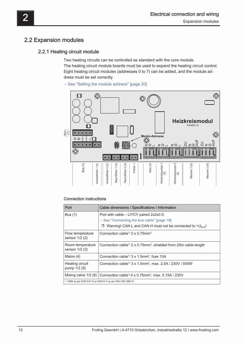
Once the update is complete, a message will appear that you can remove the stick❒ Remove the USB stick❒ Close the USB cover cap on the barrel
➥ The cap must click into place❒ Tap the touch screen
After restarting the display will start calibrating. Once the calibration is complete, it will restart again to finish. The touch control soft‐ware is now up to date.
NOTICE
Inaccurate calibration
If you do not tap the indicated points accurately, the control may stop workingproperly and a software update may be required.
Overview of the basic functions 3Updating the software of the touch control
Operating Instructions Lambdatronic S 3200 - Touch | B0840314_en 27

3.4 Calibrating the touchscreenIf the touchscreen stops working properly, it will need to be calibrated.❒ Go to the “Display settings” menu❒ Scroll down with the down arrow until the “Software update / Service" submenu
appears and open the submenu
❒ In the “Software update / Service" menu open the “Recalibrate touch con-
trol” parameter
3 Overview of the basic functionsCalibrating the touchscreen
28 Froling GesmbH | A-4710 Grieskirchen, Industriestraße 12 | www.froeling.com

❒ Set the parameter to “YES” and confirm at the bottom right➥ The touchscreen will restart and begin calibrating
To calibrate the touchscreen, you much press five points indicated by a crosshair inthe order shown. The control will restart after calibration.
NOTICE
Inaccurate calibration
If you do not tap the indicated points accurately, the control may stop workingproperly and a software update may be required.
Overview of the basic functions 3Calibrating the touchscreen
Operating Instructions Lambdatronic S 3200 - Touch | B0840314_en 29

4 Operation
4.1 Before switching on for the first time
NOTICE
You should have the initial startup carried out by the authorised heating engineerfrom Froling customer services.
4.1.1 Controller check❒ Check boards for foreign bodies (pieces of wire, washers, screws ...)❒ Carry out a wiring check:
Check for loose, uninsulated wires, which could cause a short-circuit❒ Check plug configuration of pumps, mixing valves and other units, which have
NOT been prepared by Froling❒ Check the connection of the BUS cable for short-circuits❒ Check the specified addresses and terminal jumpers on the individual modules
(heating circuit modules, hydraulic modules, displays etc.)⇨ See "Setting the module address" [page 20] and⇨ See "Setting end jumpers" [page 19]
4.1.2 Check on the connected units❒ Check that all units that are used are connected correctly❒ Carry out a wiring check:
Check for loose or uninsulated wires in the terminal boxes of the pumps, mixer and switch valve, which could cause a short-circuit
4.1.3 System Check❒ Check that the main fuse for the boiler has a sufficient rated amperage (16A )
➥ If a safety overload switch is used, it should be a type with 16A.
4 OperationBefore switching on for the first time
30 Froling GesmbH | A-4710 Grieskirchen, Industriestraße 12 | www.froeling.com

4.2 Navigation within the info menuThe info menu displays all the information about the system. Use the right and left ar‐rows to go to the individual menu items for the relevant information. The next time youopen the info menu, the last page viewed will be displayed.
4.3 Navigation within the system menuThe system menu shows the menu items available depending on the user level andthe system configuration. Tap the icon to open the corresponding menu item. The sys‐tem menu is structured in a circular buffer, which can be navigated using the right andleft arrows. The next time you open the system menu, the last page viewed will be dis‐played.
Operation 4Navigation within the info menu
Operating Instructions Lambdatronic S 3200 - Touch | B0840314_en 31

4.3.1 Navigating the menusAfter you open a menu item, the corresponding status display with current values willappear. If, for example, several heating circuits are installed, you can use the right andleft arrows to navigate to the desired heating circuit. You can open any other menuitems available in the same way.
The individual menus are divided into tabs for quicker navigation.❒ Tap on the desired tab
➥ The list of parameters for the selected area will appear
The parameter list shows three parameters. The up and down arrows can be used toscroll through longer lists of parameters. If you have reached the start or end of theparameter list, the relevant arrow symbol will become inactive.
4 OperationNavigation within the system menu
32 Froling GesmbH | A-4710 Grieskirchen, Industriestraße 12 | www.froeling.com

Operation 4Navigation within the system menu
Operating Instructions Lambdatronic S 3200 - Touch | B0840314_en 33

4.4 Adjusting parametersA parameter can only be adjusted if there is a pen icon beside it. Depending on thetype of parameter, either the numeric keypad...
... or a list box will appear.
In both cases you need to tap the confirm icon to save the entry.
4 OperationAdjusting parameters
34 Froling GesmbH | A-4710 Grieskirchen, Industriestraße 12 | www.froeling.com

4.5 Setting timesThe desired time window for the component can be set in the "Times" tab in the indi‐vidual menus of the heating components (heating circuits, DHW tanks etc.). The struc‐ture of the time menu and the procedure for changing the times are always the same.❒ Use the left or right arrow to navigate to the desired day of the week❒ Tap the symbol under the day of the week
➥ The edit window will appear
You can specify up to four time windows per component and day.❒ Tap the desired time window
❒ The time window will open for editing
❒ Set the start and end time for the time window using the up and down arrows❒ Save the time window setting by tapping on the confirm icon
Operation 4Setting times
Operating Instructions Lambdatronic S 3200 - Touch | B0840314_en 35

To delete a time window, set the times so that the hour and minute displays are re‐placed by two dashes.
If you want to apply the time window setting to another day in addition, you can do thisby activating the relevant day.
4 OperationSetting times
36 Froling GesmbH | A-4710 Grieskirchen, Industriestraße 12 | www.froeling.com

4.6 Setting the date/time❒ To set / adjust the date and time displayed, tap on the date/time at the top right of
the basic display.
❒ A menu will then appear allowing you to adjust the date and time. To apply the
new values you need to confirm the date and time by tapping the “confirm” icon.
Operation 4Setting the date/time
Operating Instructions Lambdatronic S 3200 - Touch | B0840314_en 37

4.7 Quick menu
4.7.1 "Operating level” functionTo change the operating level you need to enter the relevant code.⇨ See "Switching user level" [page 39]
4.7.2 "Choose language” functionThe control starts in German by default. If you change the language of the control, itwill restart, uploading all text in the selected language from the core module.
4.7.3 "Chimney sweep” functionThe chimney sweep function is used for measuring boiler emissions using the chim‐ney sweeper. For further information and the procedure for measuring emissions, seethe operating instructions of the boiler and/or the “Instructions for the procedure formeasuring emissions for the firewood boiler”.❒ The boiler runs for 45 minutes at nominal load
➥ The boiler temperature setpoint is set to 85 °C➥ The heating pumps switch on and the mixer valves regulate to the maximum
flow temperature setpoint➥ DHW tank and storage tank loading pump are controlled as normal
4.7.4 "Extra heating” functionDuring extra heating, heating and domestic hot water are heated for 6 hours. Themode setting is ignored.Caution: The external temperature heating limit set in the "Heating" menu is active andcan prevent release of the heating circuits.
4.7.5 “Mode in automatic mode” functionIf you want to stop the chimney sweeper function early, you can switch back to auto‐matic mode by tapping this symbol.
4.7.6 "Extra loading” functionOne-off manual loading of domestic hot water. After loading, the mode that was previ‐ously set becomes active again.
4.7.7 “Ignition” functionDirectly opens the ignition settings of the automatic hot air ignition.⇨ See "Menu - Ignition" [page 72]
4.7.8 "Touch cleaning” functionFor cleaning the touchscreen surface. The screen is disabled for 10 seconds to allowyou to clean it without opening a menu or inadvertently adjusting a parameter.
4 OperationQuick menu
38 Froling GesmbH | A-4710 Grieskirchen, Industriestraße 12 | www.froeling.com

4.8 Initial startup
4.8.1 Switching user levelThe range of functions of the touch display depends on the current user level setting.To switch to another user level, open the “Operating level” function in the quick menu. ⇨ See "Quick menu" [page 38]
Once you have entered and confirmed the relevant user code, the number of functionsavailable will vary. The “installer" and “service" user levels are also shown on the ba‐sic display above the quick menu icon.
Operating level Description
Child lock(Code 0)
At “Child lock” level, only the “Status” menu appears. It is notpossible to change parameters at this level.
Customer(Code 1)
Standard level for normal operation of the touch display. All cus‐tomer-specific parameters are displayed and can be changed.
Installer / Service Releases parameters to adjust the controller to the system com‐ponents (if configured).
Operation 4Initial startup
Operating Instructions Lambdatronic S 3200 - Touch | B0840314_en 39

4.8.2 Setting the system selection
Open the system selection menu❒ In the system menu open “System”
❒ Then navigate to “System selection” in the menu and open the menu
4 OperationInitial startup
40 Froling GesmbH | A-4710 Grieskirchen, Industriestraße 12 | www.froeling.com

Selecting the boiler type❒ In the boiler type menu select the “S4 Turbo” firewood boiler
❒ Then set the boiler output entered on the identification plate and confirm.
❒ Activate any other relevant parameters
➥ Active parameters are identifiable by the confirm icon
Operation 4Initial startup
Operating Instructions Lambdatronic S 3200 - Touch | B0840314_en 41

Lambda probe installed YES
Actuators installed YES
Ignition available YES
Bypass pump installed NO
Return mixer using HC1 NO
Return mixer using external mixer module NO
NOTE: Once all the relevant parameters have been set, the boiler standard valuesneed to be entered in the “Boiler” menu under “General settings”.
Parameter Description
Very dry material NO If this parameter is set to "YES" and the boiler standardvalues are adopted, the parameters are automaticallyadjusted for very dry firewood.
Adopt boiler standard val‐ues
NO If this parameter is set to "YES", the current parametersfor the selected boiler are set. After the values havebeen adopted the parameter jumps to "NO"
4 OperationInitial startup
42 Froling GesmbH | A-4710 Grieskirchen, Industriestraße 12 | www.froeling.com

System selection
Hydraulic system 0Hydraulic system 1Hydraulic system 2Hydraulic system 3Hydraulic system 4
SELECTFor description see “ Lambdatronic S 3200Energy Systems” brochure
Hydraulic system for S3 boiler DO NOT SELECT
Hydraulic system 12Hydraulic system 13
SELECTFor description see “ Lambdatronic S 3200Energy Systems” brochure
Variant 1Variants 2 and 5Variant 3Variant 4
Multiple house diagrams
Slave boiler for boiler sequence control Only for systems in the cascade!
Operation 4Initial startup
Operating Instructions Lambdatronic S 3200 - Touch | B0840314_en 43

If the system has a Non-binding Planning Suggestion, the hydraulic system settingcan be found at the top right-hand corner of the planning suggestion.Otherwise, the selection table below shows the hydraulic system to be set for the spe‐cific system:
DHW tank system
DHW tank 01 installed ❒
DHW tank 02 installed ❒
4 OperationInitial startup
44 Froling GesmbH | A-4710 Grieskirchen, Industriestraße 12 | www.froeling.com

: :
DHW tank 08 installed ❒
Heating system
Heating circuit 01 installed ❒
Remote control 01 installed ❒
Heating circuit 02 installed ❒
Remote control 02 installed ❒
: :
Heating circuit 18 installed ❒
Remote control 18 installed ❒
❒ The “remote control XX installed” parameter should be checked if any of the thethree remote controls shown is used for the respective heating circuit.
Solar system
Solar collector 01 installed ❒
A second pump is used instead of the isolating valve ❒
Operation 4Initial startup
Operating Instructions Lambdatronic S 3200 - Touch | B0840314_en 45

Boiler remote control
Remote control of the boiler can be activated ❒
4.8.3 Before heating up for the first time❒ Check the system pressure of the heating system❒ Check that the heating system is fully ventilated❒ Check that the safety devices are present and working correctly❒ Check that there is sufficient ventilation in the boiler room❒ Check the seal of the boiler
➥ All doors and inspection openings must be tightly sealed! ❒ Calibrate the broadband probe
⇨ See "Starting calibration" [page 91] ❒ Check that the Door switch is working correctly
⇨ See "Digital inputs" [page 84]
Drives❒ Check that drives and actuators are working and turning in the right direction
⇨ See "Analogue outputs" [page 83] and ⇨ See "Digital outputs" [page 83]
4 OperationInitial startup
46 Froling GesmbH | A-4710 Grieskirchen, Industriestraße 12 | www.froeling.com
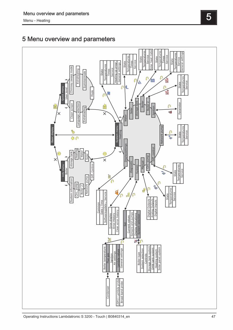
5 Menu overview and parameters
Menu overview and parameters 5Menu - Heating
Operating Instructions Lambdatronic S 3200 - Touch | B0840314_en 47

5.1 Menu - Heating
⇨ See "Navigation within the system menu" [page 31]
5.1.1 Status displays for the heating circuits
Parameter Description
Control heating circuit according toprogram (NO -> heating circuit isswitched off)
YES NO -> Heating circuit is completely switched off. No frost protection!
Actual flow temperature 46°C Shows the current flow temperature
Flow temperature setpoint 52°C The calculated flow temperature setpoint
Room temperature 21°C Temperature on remote control of the current heating circuit (optional)
Override switch Auto Shows the current switch setting on the remote control (optional)
(Party) = party mode; the setback program is ignored
(Setback) = setback mode; the heating phases are ignored
(Auto) = automatic mode; heating phases according to setbackprogram
(Off) = switched off; heating circuit deactivated, only frost protection!
External temperature 2°C Shows the current external temperature
5 Menu overview and parametersMenu - Heating
48 Froling GesmbH | A-4710 Grieskirchen, Industriestraße 12 | www.froeling.com

5.1.2 Temperature settings for the heating circuits
Parameter Description
Desired room temperature duringheating mode
20°C Room temperature during heating mode (only with remote control)
Desired room temperature duringsetback mode
16°C Room temperature during setback mode (only with remote control)
Flow temperature SP at externaltemperature of +10°C
40°C The heating curve can be adjusted to the relevant system with these twowork points.
90
80
70
60
50
40
30
20
Flo
w tem
pera
ture
-10
External temperature
-15 -5 0 5 10 15 20
Example offloor heating
Example ofradiators
Flow temperature SP at externaltemperature of -10°C
60°C
Controller gain room temperatureKp-Rm
6.0 Influencing factor of room temperature on the flow temperature of theheating circuit. If there is a deviation in the room temperature of +/- 1°Cthe set value of the flow temperature is corrected by this value.(Parameter only with optional remote control!)Recommended values for:- Floor heating 2 - 3- Radiators (new build): 4 – 5- Radiators (old build): 6 – 7Note:Observe external influences on the room sensors!
Reduction of flow temperature insetback mode
15°C The flow temperature is reduced by this value during setback mode.
External temperature below whichthe heating circuit pump switches onin heating mode
18°C If the external temperature exceeds this value during heating, the heatingcircuit pumps and mixing valve are deactivated.
External temperature below whichthe heating circuit pump switches onin setback mode
7°C If the external temperature falls below this value in setback mode, theheating circuit pumps and mixing valve are activated.
Menu overview and parameters 5Menu - Heating
Operating Instructions Lambdatronic S 3200 - Touch | B0840314_en 49

Maximum heating circuit flow temp. 75°C Maximum temperature for limiting outfeed temperature at which the heat‐ing circuit is supplied.
Maximum DHW tank flow temp. 75°C If DHW tank 1 is supplied directly from heating circuit 1, you can set anoth‐er maximum flow temperature for the time of DHW tank loading.
Frost protection temperature 10°C If the room temperature or the flow temperature is lower than the set val‐ue, the heating circuit pump will be switched on.
5.1.3 Heating times of the heating circuits
⇨ See "Setting times" [page 35]
5.1.4 Service parameters of the heating circuits
Parameter Description
Heating circuit pump A 0 Used for testing the individual outputs.
Heating circuit mixing valve OPEN A 0
Heating circuit mixing valveCLOSED
A 0
Mixer runtime 240s Set mixer runtime of heating circuit mixer in use.Recommendation to reduce mixer vibration: do not set to < 150 s
Switch off heating circuit pumpwhen flow setpoint is lower than
20°C If a flow temperature setpoint is calculated below the value set here, theheating circuit pump switches off and the mixing valve closes (just withoutremote control).
5 Menu overview and parametersMenu - Heating
50 Froling GesmbH | A-4710 Grieskirchen, Industriestraße 12 | www.froeling.com

Parameter Description
Should this heating circuit heatwhen there is DHW tank priority?
NO Generally the heating circuits are released with active DHW tank priorityonly when the DHW tank is fully charged. If this parameter is set to "YES",the DHW tank priority for this heating circuit is deactivated.
From which storage tank or distribu‐tor is the heating circuit supplied (0= boiler)
1 NOTE: Only valid for multiple house systems (variants).Allocation of the heating source for this heating circuit:0 = Boiler, 1 = Storage tank 01, ...
High temperature requirement be‐cause of DHW tank 1 loading
NO If DHW tank 1 is supplied directly from the heating circuit as well as theisolating valve, this parameter must be set to “YES”. If there is a require‐ment from the DHW tank and the criteria for DHW tank loading have beenmet, the isolating valve immediately clears the way for boiler loading. Theheating circuit pump starts running as soon as the “Load if tempera-ture difference between boiler and DHW tank is” criterionis reached. Once DHW tank loading is complete, the heating circuit pumpwill stop, the isolating valve will remain active for a specified period of timeand the heating circuit mixer will close. If time has run out, the heating cir‐cuit will go back to being supplied on a weather-compensated basis.NOTE: Parameter only available with heating circuit 1 and generally onlyused in conjunction with the unit model of the P1 Pellet pellet boiler!
High temperature requirement be‐cause of DHW tank loading
NO If this parameter is set to YES, the remote line is operated according tothe set heating curve + overcharge. Whilst the DHW tank is loading, theremote line is supplied for a short time at a higher temperature, but oncethe DHW tank is loaded, it is supplied again according to the heatingcurve.NOTE: Parameters for heating circuit 2 only!
For high temperature requirementdon't look at DHW tank 01
NO If DHW tank 1 is positioned in front of the network mixer, it should not af‐fect the temperature control of the remote line, therefore this parametershould be set to YES.NOTE: Parameters for heating circuit 2 only!
⇨ See "Digital outputs" [page 83]
5.1.5 Service parameters for heating up program
Menu overview and parameters 5Menu - Heating
Operating Instructions Lambdatronic S 3200 - Touch | B0840314_en 51
Parameter Description
Heating up program active NO If this parameter is activated, the 30-day program that has been set starts.After the 30 days, the heating circuit that has been set operates based onthe set heating times again.❒ The heating times of the selected heating circuit are automatically set
to 0:00-24:00 and the external temperature heating limit is ignored.❒ In order that enough heat is always available to the heating circuit, the
boiler and/or storage tank loading times must be set to 0:00-24:00.When using a firewood boiler, a corresponding heat supply must beensured.
Current day of the heating up pro‐gram
1 Shows the current day of the heating program that is running
For which heating circuit should theprogram apply
1 This parameter determines which heating circuit is supplied by the heatingup program. Heating circuit 1 ... 18❒ Only one heating circuit can be selected.
Which heating up program is used 1 There are set options for the progression of the flow temperature in heat‐ing up programs 1 – 6. With heating up program 7 the flow temperaturecan be selected freely.
Outfeed setpoint for all days in pro‐gram 7
35°C If heating up program 7 is active, the selected heating circuit is adjusted tothe specified flow temperature.
⇨ See "Heating up programs" [page 53]
5 Menu overview and parametersMenu - Heating
52 Froling GesmbH | A-4710 Grieskirchen, Industriestraße 12 | www.froeling.com

Heating up programs
Heating up program 1:
0
5
10
15
20
25
30
35
40
45
50
55
1 6 11 16 21 26
Day
Flo
wte
mp
.setp
oin
t[°
C]
30
Heating up program 2:
0
5
10
15
20
25
30
35
40
45
50
1 6 11 16 21 26
Day
Flo
wte
mp
.setp
oin
t[°
C]
30
Heating up program 3:
0
5
10
15
20
25
30
35
40
45
50
1 6 11 16 21 26
Day
Flo
wte
mp
.setp
oin
t[°
C]
30
Heating up program 4:
0
5
10
15
20
25
30
35
40
45
1 6 11 16 21 26
Day
Flo
wte
mp
.setp
oin
t[°
C]
30
Heating up program 5:
0
5
10
15
20
25
30
35
40
45
50
55
1 6 11 16 21 26
Day
Flo
wte
mp
.setp
oin
t[°
C]
30
Heating up program 6:
0
5
10
15
20
25
30
35
40
45
50
55
60
1 6 11 16 21 26
Day
Flo
wte
mp
.setp
oin
t[°
C]
30
Heating up program 7:
0
5
10
15
20
25
30
35
40
1 6 11 16 21 26
Day
Flo
wte
mp
.setp
oin
t[°
C]
30
The heating up programs listed are non-binding rec‐ommendations. If the heating up program is to beused for floor screed drying, you must consult themanufacturer of the floor finish and/or the installer
Menu overview and parameters 5Menu - Heating
Operating Instructions Lambdatronic S 3200 - Touch | B0840314_en 53

5.1.6 General Settings
Parameter Description
Correction value for external sensor
0°C If the outside temperature sensor shows an incorrect value, the value canbe adjusted using this parameter.
Heating circuit module to which the external sensor is con‐nected(0 = core module)
0 If the outside temperature sensor is not connected to the core module, theaddress of the relevant heating circuit module +1 must be set here. (Sen‐sor 1 on relevant module)
Use room temperature sensor inputfor room thermostat
NO If room thermostats are used instead of room temperature sensors, thisparameter must be set to YES.
5 Menu overview and parametersMenu - Heating
54 Froling GesmbH | A-4710 Grieskirchen, Industriestraße 12 | www.froeling.com

5.2 Menu - Water
⇨ See "Navigation within the system menu" [page 31]
5.2.1 Status displays for the DHW tank
Parameter Description
DHW tank top temperature 60°C Current temperature in the top part of the DHW tank. The DHW tank isheated during the loading times until the specified parameter, "Set DHWtemperature", is reached.
DHW tank bottom temperature 55°C Current temperature in the lower part of the DHW tank.(Parameter only available with solar element)
DHW tank pump control 0% Specifies the speed of the DHW tank pump as a percentage of the maxi‐mum speed
5.2.2 Temperature settings of the DHW tank
Parameter Description
DHW setpoint 55°C When this DHW tank temperature is reached the DHW tank loading pumpswitches off.
Reload if DHW tank temperature isbelow
45°C Reloading of the DHW tank is authorised when the DHW tank temperatureis below this level.
Menu overview and parameters 5Menu - Water
Operating Instructions Lambdatronic S 3200 - Touch | B0840314_en 55
Load if temperature difference be‐tween storage tank and DHW tankis
6°C When the storage tank top temperature is above the DHW tank tempera‐ture by this value, the DHW tank loading pump is released.(Only for systems with storage tanks)
Load if temperature difference be‐tween boiler and DHW tank is
6°C Initial value of DHW tank loading. The boiler temperature must be higherthan the DHW tank temperature by this value so that the DHW tank load‐ing process begins.(Only for systems without storage tanks)
5.2.3 Heating times of the DHW tank
⇨ See "Setting times" [page 35]
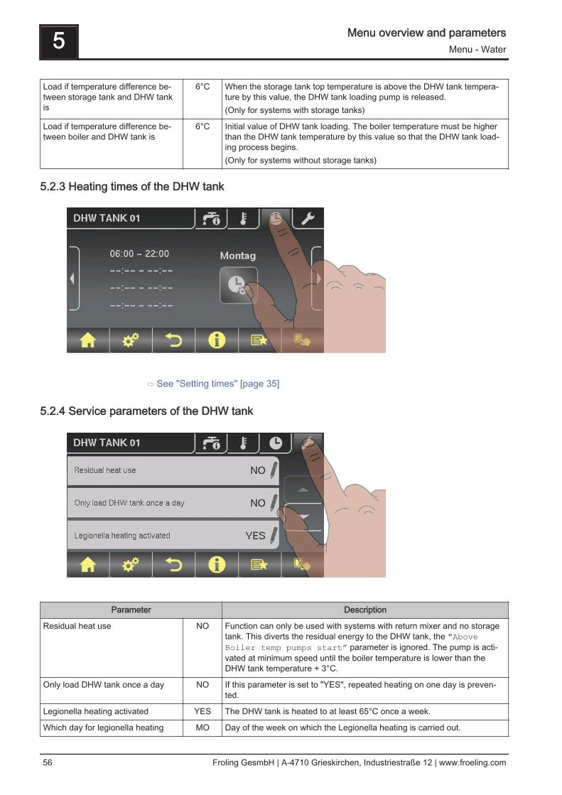
5.2.4 Service parameters of the DHW tank
Parameter Description
Residual heat use NO Function can only be used with systems with return mixer and no storagetank. This diverts the residual energy to the DHW tank, the "AboveBoiler temp pumps start” parameter is ignored. The pump is acti‐vated at minimum speed until the boiler temperature is lower than theDHW tank temperature + 3°C.
Only load DHW tank once a day NO If this parameter is set to "YES", repeated heating on one day is preven‐ted.
Legionella heating activated YES The DHW tank is heated to at least 65°C once a week.
Which day for legionella heating MO Day of the week on which the Legionella heating is carried out.
5 Menu overview and parametersMenu - Water
56 Froling GesmbH | A-4710 Grieskirchen, Industriestraße 12 | www.froeling.com

Parameter Description
Which storage tank or heat distribu‐tor supplies the heat to this DHWtank (0 = boiler)
1 When using several storage tanks or heat distributors, the source of heatfor DHW tank loading is selected here.If only one storage tank or heat distributor is used, leave the parameter atthe default setting of 1.NOTE: Only valid for multiple house systems.
DHW tanks run-on (this parameterapplies for all DHW tanks)
0m Run-on time for all DHW tanks
Which sensor is used for top DHWtank 1
0.3 Bus address of the sensors and pumps used.⇨ See "Setting the module address" [page 20] Which sensor is used for solar refer‐
ence DHW tank 10.4
Which pump is used for DHW tank 1 0.2
PWM setting for DHW tank pump Normalpump
▪ Normal pump▪ PWM / field pump▪ PWM / solar pump▪ PWM field pump + valve▪ 0 – 10V / field pump▪ 0 – 10V / solar pump▪ 0 – 10V field pump + valve
Properties of the respective setting:⇨ See "PWM / 0 - 10V settings" [page 102]
Minimum DHW tank pump speed 45% Adjustment of the minimum speed to the pump type. (Set the pump modeaccording to pump manufacturer’s instructions)
Maximum DHW tank pump speed 100% If you need to limit the maximum speed of the DHW tank pump for system‐ic reasons, you can do so by adjusting this parameter.
Menu overview and parameters 5Menu - Solar
Operating Instructions Lambdatronic S 3200 - Touch | B0840314_en 57

5.3 Menu - Solar
⇨ See "Navigation within the system menu" [page 31]
5.3.1 Status displays for the solar system
Parameter Description
Collector Temperature 80°C Current temperature at collector.
Solar temperature bottom storagetank
43°C Current temperature at solar sensor at bottom of storage tank.
Collector return feed temperature 50°C Current temperature at collector return.(Only for systems 12, 13)
Current output of Solar WMZ [kW] 0.00 Displays current output of solar collector.
DFL Sensor [l/h] 0 Display of the water quantity currently being pumped through the solar col‐lector.NOTE: Display is active only if an external volume flow sensor is used andit has been activated in the controller.
Todays yield [kWh]] 0 Heat quantity that has been supplied by the solar panel system today
Total yield [kWh] 0 Heat quantity that has been supplied since activation of the solar panelsystem
DHW tank bottom temperature 39°C Current temperature at the solar reference sensor in the DHW tank.
Heat exchanger sec. return feedtemperature (line to storage tank)
78°C Current temperature at heat exchanger flow on the secondary side. (onlyfor systems 12, 13)
Collector pump runtime 1 h Specifies the runtime of the collector pump.
Collector pump control 52% Specifies the speed of the collector pump as a percentage of maximumspeed.
Pump between heat exchanger andstorage tank
100% Current speed of the pump between heat exchanger and storage tank (on‐ly for systems 12, 13)
5 Menu overview and parametersMenu - Solar
58 Froling GesmbH | A-4710 Grieskirchen, Industriestraße 12 | www.froeling.com

Parameter Description
Pump between heat exchanger andDHW tank
0% Current speed of the pump between heat exchanger and DHW tank (onlyfor system 12)
Diverter valve for top/bottom coils 0% Current control of the isolating valve on the solar side. If the valve is cor‐rectly fitted:0% ... storage tank below100% .. storage tank aboveIf the valve is incorrectly fitted, the output of the isolating valve can be in‐verted in the Service menu.Service parameters of the solar system(only with system 12, 13)
5.3.2 Temperature settings for the solar system
Parameter Description
Boiler target temperature during so‐lar charging
75°C Up to this temperature the DHW tank is heated by the solar system.
Temp differential to start collectorpump
10°C The collector loading pump activates when the collector temperature ex‐ceeds the storage or DHW tank temperature by this value.
Temp difference to stop collectorpump
5°C The collector loading pump switches off when the collector temperatureexceeds the storage or DHW tank temperature by this value.
Maximum storage tank bottom tem‐perature during solar charging
85°C Maximum bottom storage tank temperature at which the collector pump isswitched off (only with storage tank).
Minimum collector temperature 20°C Below this collector temperature the collector pump is switched off.
Heat exchanger - storage tankpump startup delay
120s Delay for switching on the pump between heat exchanger and storagetank (only for systems 12, 13).
Heat exchanger - storage tankpump stop delay
240 s Delay for switching off the pump between heat exchanger and storagetank (only for system 12, 13).
Storage tank top solar setpoint (fastloading until this temperature)
60°C Once the top storage tank sensor reaches the set value during solarcharging, the isolating valve switches to bottom storage tank (Only withsystems 12, 13).
Collector - storage tank top differen‐tial
20°C This is the overcharge for the collector pump controller for the top or bot‐tom storage tank temperature.
Collector - heat exchanger sec., out‐feed difference
10°C This parameter specifies how much the heat exchanger secondary out‐feed should be below the collector temperature. If the temperature is toolow, the speed of the storage tank or DHW tank pump will be reduced.
Collector return - storage tank bot‐tom differential
20°C Storage tank bottom plus the set value produces the desired temperatureof the collector return. If the collector return is too high, the storage tankpump speed is reduced.
Menu overview and parameters 5Menu - Solar
Operating Instructions Lambdatronic S 3200 - Touch | B0840314_en 59
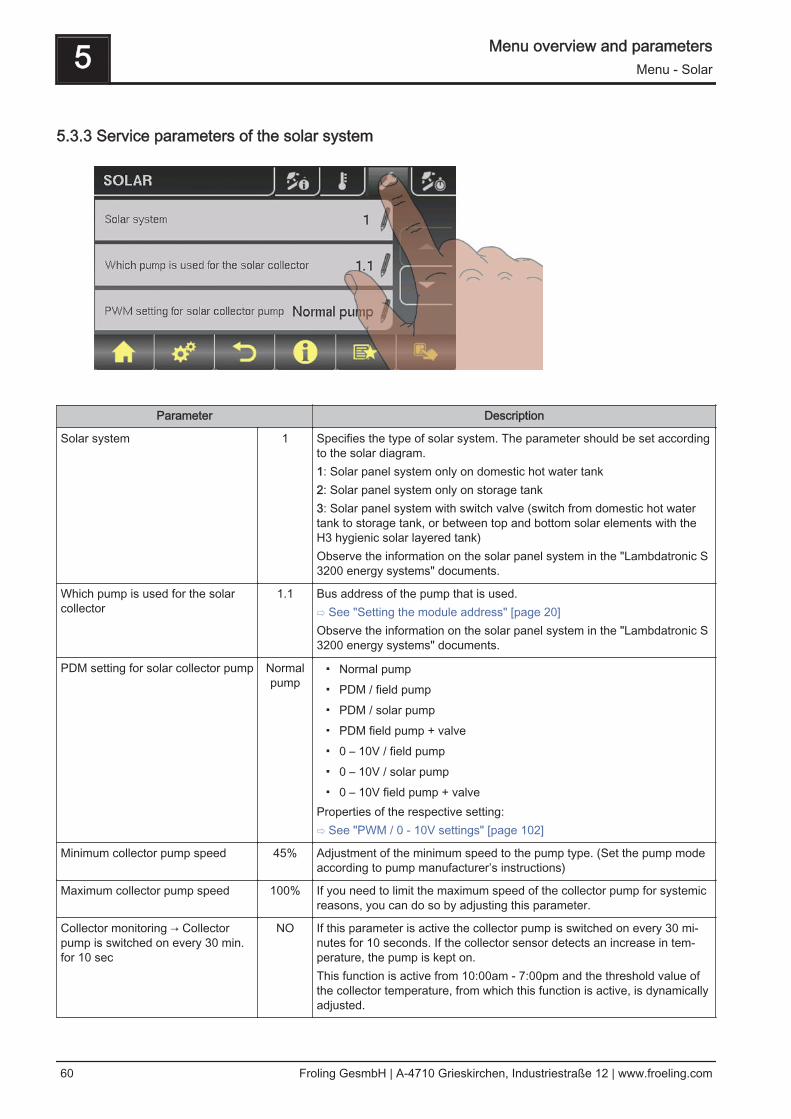
5.3.3 Service parameters of the solar system
Parameter Description
Solar system 1 Specifies the type of solar system. The parameter should be set accordingto the solar diagram.1: Solar panel system only on domestic hot water tank2: Solar panel system only on storage tank3: Solar panel system with switch valve (switch from domestic hot watertank to storage tank, or between top and bottom solar elements with theH3 hygienic solar layered tank)Observe the information on the solar panel system in the "Lambdatronic S3200 energy systems" documents.
Which pump is used for the solarcollector
1.1 Bus address of the pump that is used.⇨ See "Setting the module address" [page 20]Observe the information on the solar panel system in the "Lambdatronic S3200 energy systems" documents.
PDM setting for solar collector pump Normalpump
▪ Normal pump▪ PDM / field pump▪ PDM / solar pump▪ PDM field pump + valve▪ 0 – 10V / field pump▪ 0 – 10V / solar pump▪ 0 – 10V field pump + valve
Properties of the respective setting:⇨ See "PWM / 0 - 10V settings" [page 102]
Minimum collector pump speed 45% Adjustment of the minimum speed to the pump type. (Set the pump modeaccording to pump manufacturer’s instructions)
Maximum collector pump speed 100% If you need to limit the maximum speed of the collector pump for systemicreasons, you can do so by adjusting this parameter.
Collector monitoring → Collectorpump is switched on every 30 min.for 10 sec
NO If this parameter is active the collector pump is switched on every 30 mi‐nutes for 10 seconds. If the collector sensor detects an increase in tem‐perature, the pump is kept on.This function is active from 10:00am - 7:00pm and the threshold value ofthe collector temperature, from which this function is active, is dynamicallyadjusted.
5 Menu overview and parametersMenu - Solar
60 Froling GesmbH | A-4710 Grieskirchen, Industriestraße 12 | www.froeling.com

Parameter Description
For solar to store and DHW tank,the DHW tank has priority
YES YES: The DHW tank is charged until the temperature setpoint is reached,and only then is the storage tank supplied.NO: The DHW tank is charged until the temperature difference betweenthe collector and the DHW tank is no longer sufficient. When the tempera‐ture difference has fallen too low, the storage tank is supplied with heat for20 minutes. Then the collector pump is stopped for 20 minutes and acheck is carried out to see if the temperature difference is now sufficientfor DHW tank charging.
Solar charging to which store 1 Defines the storage tank to which the solar charging takes place.
Solar charging to which DHW tank 1 Defines the DHW tank to which the solar charging takes place.
Which sensor is used for the solarcollector
1.1 Bus addresses of the sensors used, depending on the system⇨ See "Setting the module address" [page 20]Observe the information on the solar panel system in the "Lambdatronic S3200 energy systems" documents.
Which sensor is used for the stor‐age tank reference
0.2
Which sensor is used for the heatexchanger sec. flow?
1.4
Which sensor is used for the collec‐tor return
1.5
Which pump is used for the solarisolating valve
1.2
Which pump is used for storagetanks - heat exchanger
2.1
PDM setting for the storage tank -heat exchanger pump
Normalpump
▪ Normal pump▪ PDM / field pump▪ PDM / solar pump▪ PDM field pump + valve▪ 0 – 10V / field pump▪ 0 – 10V / solar pump▪ 0 – 10V field pump + valve
Properties of the respective setting:⇨ See "PWM / 0 - 10V settings" [page 102]
Which pump is used for DHW tanks- heat exchanger
2.2 Bus addresses of the sensors used, depending on the system⇨ See "Setting the module address" [page 20]Observe the information on the solar panel system in the "Lambdatronic S3200 energy systems" documents.
PDM setting for the DHW tank -heat exchanger pump
Normalpump
▪ Normal pump▪ PDM / field pump▪ PDM / solar pump▪ PDM field pump + valve▪ 0 – 10V / field pump▪ 0 – 10V / solar pump▪ 0 – 10V field pump + valve
Properties of the respective setting:⇨ See "PWM / 0 - 10V settings" [page 102]
Invert isolating valve NO For DHW tank loading through the collector, the isolating valve is activatedwith 230V. If the valve switches incorrectly, the way it is controlled can beadjusted using this parameter.
Menu overview and parameters 5Menu - Solar
Operating Instructions Lambdatronic S 3200 - Touch | B0840314_en 61
Parameter Description
Is a PT1000 sensor used as a solarsensor?
NO Basic setting for the sensor type used:NO: Solar sensor - FrolingYES: Sensor PT1000
Collector pump control Kp value 1.00 Control parameter for collector pump
Collector pumps control Tn value 300s
5.3.4 Solar heat meter
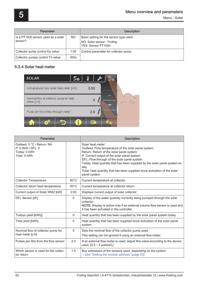
Parameter Description
Outfeed: 0 °C / Return: NAP: 0.0kW / DFL: 0Today: 0 kWhTotal: 0 kWh
Solar heat meter:Outfeed: Flow temperature of the solar panel systemReturn: Return of the solar panel systemP: Current output of the solar panel systemDFL: Flow-through of the solar panel systemToday: Heat quantity that has been supplied by the solar panel system to‐dayTotal: heat quantity that has been supplied since activation of the solarpanel system
Collector Temperature 80°C Current temperature at collector.
Collector return feed temperature 50°C Current temperature at collector return.
Current output of Solar WMZ [kW] 0.00 Displays current output of solar collector.
DFL Sensor [l/h] 0 Display of the water quantity currently being pumped through the solarcollector.NOTE: Display is active only if an external volume flow sensor is used andit has been activated in the controller.
Todays yield [kWh]] 0 Heat quantity that has been supplied by the solar panel system today
Total yield [kWh] 0 Heat quantity that has been supplied since activation of the solar panelsystem
Nominal flow of collector pump forheat meter [L/h]
0 Sets the nominal flow of the collector pump used.This setting can be ignored if using an external flow meter.
Pulses per litre from the flow sensor 2.0 If an external flow meter is used, adjust this value according to the deviceused. [0.5 – 5 pulses/L]
Which sensor is used for the collec‐tor return
1.5 Bus addresses of the sensors used, depending on the system⇨ See "Setting the module address" [page 20]
5 Menu overview and parametersMenu - Solar
62 Froling GesmbH | A-4710 Grieskirchen, Industriestraße 12 | www.froeling.com

Which sensor is used for heat meterflow temperature
1.3 If a flow temperature sensor is used for the heat meter in addition to thecollector sensor, set the sensor address accordingly.Bus addresses of the sensors used, depending on the system⇨ See "Setting the module address" [page 20]
Is an external flow through counterused
NO If an external volume flow sensor is used in the collector return, set thisparameter to “YES”.
Menu overview and parameters 5Menu - Storage tank
Operating Instructions Lambdatronic S 3200 - Touch | B0840314_en 63

5.4 Menu - Storage tank
⇨ See "Navigation within the system menu" [page 31]
5.4.1 Status displays of the storage tank
Parameter Description
Storage tank top temperature 58°C Current temperature at top storage tank sensor.
Storage tank middle temperature 53°C Current temperature at middle storage tank sensor (depending on configu‐ration).
Storage tank bottom temperature 50°C Current temperature at bottom storage tank sensor.
Store pump control 50% Specifies the current speed of the storage tank pump as a percentage ofthe maximum speed.
Store charge 25% Shows the current storage tank charge.
5.4.2 Temperature settings for the storage tank
Parameter Description
Heating circuit release from follow‐ing storage tank temperature
30°C Minimum value of storage tank top temperature for heating circuit releasein combinations with a storage tank
5 Menu overview and parametersMenu - Storage tank
64 Froling GesmbH | A-4710 Grieskirchen, Industriestraße 12 | www.froeling.com

Temperature difference betweenboiler and border layer
20°C If the option, "Middle storage tank temperature sensor installed" and theparameter, "Mid store controller active" have been set to "YES", the con‐troller attempts keep the temperature of the "middle store" sensor to thevalue of the boiler temperature setpoint minus the temperature differenceset here, by regulating the speed of the storage tank pump.
Boiler start if difference betweenboiler setpoint and top store is larg‐er
15°C If the difference between the top store and the boiler setpoint is greaterthan the specified value, the boiler starts.
Load storage tank completely if tem‐perature difference between boilerand bottom storage tank is lowerthan
10°C Temperature difference between boiler and storage tank temperature toenable storage tank loading.
Top store temp. when the start-uprelief valve switches to bottom store
60°C If the temperature set is exceeded at sensor 0.1 the start relief valveswitches to bottom storage tank
Storage tank charge is 100% at boil‐er setpoint parameter
4°C 100% storage tank charge is calculated from the specified boiler tempera‐ture setpoint minus the specified value.
Store charge is 0% at the followingtemperature (absolute value)
30°C If the average temperature in the storage tank is less than the specifiedvalue, the storage tank has a charge of 0%.
5.4.3 Service parameters of the storage tank
Parameter Description
Enable heating circuit pump 0 ac‐cording to top store
NO NO: Release of heating circuit pump 0 from boiler temperatureTemperature settings for the boilerParameter "Minimum boiler temperature to release allpumps".YES: Release of heating circuit pump 0 from top storage tank temp.Temperature settings for the storage tankParameter "Heating circuit release from following storagetank temperature"
Residual heat use NO The residual energy is diverted to the DHW tank, the parameter "Pumpsstart at" is ignored. The pump is activated at minimum speed until theboiler temperature is lower than the bottom storage tank temperature +3°C.NOTE: Only possible with return temperature control using mixing valve!
Mid store controller active?If No the sensor is only a display
NO NOMiddle storage tank temperature sensor is used to display the temp.YESMiddle storage tank temperature sensor is used for the border layer load‐ing function.
Menu overview and parameters 5Menu - Storage tank
Operating Instructions Lambdatronic S 3200 - Touch | B0840314_en 65

Which sensor is used for storage tank top
0.1 Parameter display depends on the system.Observe the information on the hydraulic system in the "Lambdatronic S3200 energy systems" documents.Which sensor is used for storage
tank sensor 20.4
Which sensor is used for storagetank sensor 3
0.6
Which sensor is used for middlestorage tank
0.6
Which sensor is used for bottom storage tank
0.2
Which pump is used for the storage tank
0.1
PDM setting for storage tank pump Normalpump
▪ Normal pump▪ PDM / field pump▪ PDM / solar pump▪ PDM field pump + valve▪ 0 – 10V / field pump▪ 0 – 10V / solar pump▪ 0 – 10V field pump + valve
Properties of the respective setting:⇨ See "PWM / 0 - 10V settings" [page 102]
Minimum storage tank pump speed 45% Adjustment of the minimum speed to the pump type. (Set the pump modeaccording to pump manufacturer’s instructions)
Maximum storage tank pump speed 100% If you need to limit the maximum speed of the storage tank pump for sys‐temic reasons, you can do so by adjusting this parameter.
Refill calculation active (sensorshave to be assigned correctly)
NO For a recommendation regarding the amount of fuel required to load upthe layered tank to appear on the display when opening the insulateddoor, set this parameter to “YES”.
Is a hygienic layered tank used? NO If a hygienic layered tank (combi tank) is used, this parameter must be setto “YES”.
Volume of storage tank used 2000 L To calculate the amount of firewood required to load the layered tank, en‐ter the volume of the layered tank installed here.
Pump outlet for store relief valve 8.1 This outlet remains active until an adjustable temperature has beenreached at the top storage tank so that only the top part of the storagetank needs to be heated. Once this temperature has been reached, theoutlet becomes inactive and the entire store volume is available to theboiler.
Invert pump outlet for store reliefvalve
NO If the valve switches incorrectly, the way it is controlled can be adjustedusing this parameter.
5 Menu overview and parametersMenu - Boiler
66 Froling GesmbH | A-4710 Grieskirchen, Industriestraße 12 | www.froeling.com

5.5 Menu - Boiler
⇨ See "Navigation within the system menu" [page 31]
5.5.1 Status displays for the boiler
Parameter Description
Boiler temperature 80°C Display of the current values for the relevant parameter.::
Flue gas temperature 176°C
Flue gas setpoint 178°C
Boiler control variable 95%
ID fan control 80%
ID fan speed 2350U
Primary air 0%
Position of primary air flap 6%
Secondary air 99%
Position of secondary air flap 95%
Sensor 1 66°C
Return feed sensor 58°C
5.5.2 Temperature settings for the boiler
Menu overview and parameters 5Menu - Boiler
Operating Instructions Lambdatronic S 3200 - Touch | B0840314_en 67

Parameter Description
Boiler temperature setpoint 80°C The boiler temperature is regulated to this temperature.
Shutdown if current boiler tempera‐ture is higher than boiler setpoint +
5°C If the boiler temperature exceeds the setpoint by this parameter value, theboiler switches to “slumber” status.
Always switch off at maximum boilersetpoint +
3°C If the boiler temperature exceeds the maximum setpoint by this parame‐ter, the boiler switches to "slumber" status. The heating circuit and storeloading pump will also begin to run to cool the boiler.
Minimum boiler temperature to re‐lease all pumps
65°C The pumps are activated at this boiler temperature. (Hysteresis 2°C)
Minimum return temperature 60°C The minimum temperature required of the return to the boiler.
5.5.3 Service parameters of the boiler
Parameter Description
Mixer runtime 240 s Set mixer runtime of the mixer in use.❒ Recommendation to reduce mixer vibration
Do not set to < 150 s
Output fire off message using HKP0 NO If the boiler changes to "Off" status, the HKP0 output is closed.
5.5.4 General Settings
5 Menu overview and parametersMenu - Boiler
68 Froling GesmbH | A-4710 Grieskirchen, Industriestraße 12 | www.froeling.com

Parameter Description
Very dry material (w < 15%) param‐eter adopt next line
NO If this parameter is set to "YES" and then the parameter “Adopt boilerstandard values” is set to “YES”, the parameters are automaticallyadjusted for very dry firewood.
Adopt boiler standard values NO If this parameter is set to "YES", the current parameters for the selectedboiler are set. After the values have been adopted the parameter jumps to"NO”.
Abort heating up --> ID fan off, closeair flaps
NO If this parameter is set to “YES”, the boiler heating up process can beaborted.NOTE: Criteria for “Off” status must be fulfilled.
Modem installed NO If the boiler has a modem for data transfer, this value must be set to"YES".
Memory cycle of data logger 5 s Do not change this value!This is the memory cycle used for saving data onto the data logger.
Send a line break when ASCII dataoutput on COM2
NO
COM 2 is used as a MODBUS inter‐face
NO YES:The COM 2 interface can be used for connection with a MODBUS (RTU /ASCII)NO:The COM 2 interface sends the most important boiler values every sec‐ond
MODBUS address 2 Adjustable parameters for MODBUS
MODBUS protocol(1 – RTU / 2 – ASCII)
1
Set hours since last maintenance to0
NO To reset the counter “Hours since last maintenance”, this parame‐ter must be set to "YES”. After the has been reset, the parameter jumps to"NO”.
Operator data
Parameter Description
Facility name 199999999 For unique identification of the boiler on the froeling-connect.com server,the facility number listed on the identification plate must be set here.
Customer no. 263586 If both the customer and the boiler number are set, they are automaticallytransferred into the commissioning report when it is saved.Boiler number 560
Menu overview and parameters 5Menu - Boiler
Operating Instructions Lambdatronic S 3200 - Touch | B0840314_en 69

5.6 Menu - Boiler 2
⇨ See "Navigation within the system menu" [page 31]
5.6.1 Status displays for the backup boiler
Parameter Description
Temperature of standby boiler
23°C Display of the current temperature of the standby boiler
Burner relay status 0 Shows the current status of the burner relay
Manual start of standby boiler(only when ID fan is switched off)
OFF When the parameter is activated the standby boiler starts.Warning! Burner blockage noted.
5.6.2 Temperature settings for the backup boiler
Parameter Description
Standby boiler start delay 10 m Start delay of the burner relay if the boiler fails (the boiler status is off, faultor shut down and the boiler temperature is 5°C below the setpoint). Instorage mode the burner relay, however, only comes on when the storagetank has cooled down.(Top storage tank temperature is lower than the highest required tempera‐ture)
Standby boiler start, if storage tanktop temperature is below
20°C Temperature at the top of the storage tank, which the temperature mustfall below for the standby boiler to be activated
5 Menu overview and parametersMenu - Boiler 2
70 Froling GesmbH | A-4710 Grieskirchen, Industriestraße 12 | www.froeling.com

Standby boiler minimum runtime 5 m Standby boiler minimum runtime
Minimum temperature of standbyboiler
55°C Minimum temperature of the standby boiler for release of standby boilerunloading output.
Temperature difference betweenstandby boiler and storage tank
10°C Minimum temperature difference between standby boiler and storage tank,which releases secondary boiler unloading output.
Oil valve shut delay 30s The switching back of the isolating valve is delayed by the specified time.
Standby boiler delivery temperature 95°C If the standby boiler exceeds the specified temperature, the isolating valveswitches and skims the boiler(only with hydraulic system 3)
5.6.3 Service parameters of the backup boiler
Parameter Description
Control backup boiler variably to thetarget value
YES If the backup boiler has no independent control, the main control takesover control of the boiler setpoints of the backup boiler.
Which sensor is used for standbyboilerWhich sensor is used for back‐up boiler
0.5 Bus address of the sensor used.⇨ See "Setting the module address" [page 20]Observe the information on hydraulic systems in the "Lambdatronic S3200 energy systems" documents.Which output is used for unloading
backup boilerPump 1
PWM setting for solar collectorpump
Normalpump
▪ Normal pump▪ PWM / field pump▪ PWM / solar pump▪ PWM field pump + valve▪ 0 – 10V / field pump▪ 0 – 10V / solar pump▪ 0 – 10V field pump + valve
Properties of the respective setting:⇨ See "PWM / 0 - 10V settings" [page 102]
Minimum speed of boiler 2 pump 45% Adjustment of the minimum speed to the pump type. (Set the pump modeaccording to pump manufacturer’s instructions)
Maximum speed of boiler 2 pump 100% If you need to limit the maximum speed of the boiler 2 pump for systemicreasons, you can do so by adjusting this parameter.
Invert backup boiler isolating valve NO For DHW tank loading through the backup boiler, the isolating valve is ac‐tivated with 230V. If the valve switches incorrectly, this parameter can beadjusted.
Menu overview and parameters 5Menu - Boiler 2
Operating Instructions Lambdatronic S 3200 - Touch | B0840314_en 71

Parameter Description
Which second boiler is installed? Oil boil‐er
Standby boiler type:- - OIL BOILER - MANUALLY FED - AUT. FED- GAS BOILER
Burner relays A 0
5 Menu overview and parametersMenu - Ignition
72 Froling GesmbH | A-4710 Grieskirchen, Industriestraße 12 | www.froeling.com

5.7 Menu - Ignition
⇨ See "Navigation within the system menu" [page 31]
Parameter Description
Automatic Ignition YES Parameter for switching automatic ignition on/off
Start ignition Dateand time
Determines how ignition takes place▪ Date and time: see parameter "Ignition time"
▪ In approx. 15 min: ignition takes place immediately after “Preventila‐tion” status
▪ Ext. release: If the boiler release contact is closed at the core module,ignition starts
▪ Buffer tank min: see parameter "Ignition time"
▪ Storage tank < outfeed max: see parameter "Ignition time"
Menu overview and parameters 5Menu - Ignition
Operating Instructions Lambdatronic S 3200 - Touch | B0840314_en 73

Parameter Description
Ignition time (date - time) 05/10 –20:00
Day (date or daily) and time setting for the start of ignition. The parameteris only active when the “Start ignition“ parameter is set to “Date andtime”, “Buffer tank min” or "Buffer < f.flow".NOTICE! The specified date must not be more than two calendar monthsin the future and not more than two months in the past!NOTICE! The boiler status must generally be “Ignition wait" for ignition tostart. Follow the instructions for heating up with the automatic ignition.Heating up with automatic ignition
“Date and time” method:Ignition starts at the specified time exactly. If the parameter is set to “daily”instead of the date, ignition starts every day at the specified time.
“Buffer tank min” method:The ignition process starts if heat is requested from the storage tank fromthe specified time (parameter "Boiler start if difference be-tween boiler setpoint and top store is larger”). The peri‐od applies from the specified time until 24:00 h on the specified date. If thespecified time is not subsequently changed and ignition is not disabled,the store loading criterion applies daily from the specified time.
"Buffer < f.flow” method:The maximum flow temperature required by the system environment (e.g.heating circuit) is compared with the current storage tank temperaturefrom the specified time. If the top storage tank temperature falls below themaximum flow temperature setpoint, the ignition process starts. The peri‐od applies from the specified time until 24:00 h on the specified date. If thespecified time is not subsequently changed and ignition is not disabled,the start criterion applies daily from the specified time.
Maximum ign. duration 15 m Specifies how long the ignition procedure should last. "Heating" statusmust be reached within this time.
⇨ See "Temperature settings for the storage tank" [page 64]
5 Menu overview and parametersMenu - Network pump
74 Froling GesmbH | A-4710 Grieskirchen, Industriestraße 12 | www.froeling.com

5.8 Menu - Network pump
⇨ See "Navigation within the system menu" [page 31]
5.8.1 Network pump status displays
Parameter Description
Network return temperature 40°C Display of the current values for the relevant parameter. Position of thesensors and pumps depending on the system used:Note the information on multiple house diagrams in the “Lambdatronic S3200 energy systems" documents.
Network pump speed 60%
Return temperature feeder 1 0°C
Speed, feeder 1 0%
Return temperature feeder 2 0°C
Speed, feeder pump 2 0%
5.8.2 Network pump temperature settings
Parameter Description
Network return temperature setpoint 50°C Settings for the desired network temperature setpoints. Position of thesensors depending on the system used:Note the information on multiple house diagrams in the “Lambdatronic S3200 energy systems" documents.
Return temperature setpoint at feeder 1
50°C
Return temperature setpointat feeder 2
50°C
Menu overview and parameters 5Menu - Network pump
Operating Instructions Lambdatronic S 3200 - Touch | B0840314_en 75
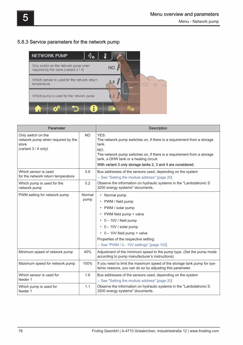
5.8.3 Service parameters for the network pump
Parameter Description
Only switch on the network pump when required by thestore(variant 3 / 4 only)
NO YES:The network pump switches on, if there is a requirement from a storagetank.NO:The network pump switches on, if there is a requirement from a storagetank, a DHW tank or a heating circuit.With variant 3 only storage tanks 2, 3 and 4 are considered.
Which sensor is used for the network return temperature
0.6 Bus addresses of the sensors used, depending on the system⇨ See "Setting the module address" [page 20]Observe the information on hydraulic systems in the "Lambdatronic S3200 energy systems" documents.
Which pump is used for the network pump
0.2
PWM setting for network pump Normalpump
▪ Normal pump▪ PWM / field pump▪ PWM / solar pump▪ PWM field pump + valve▪ 0 – 10V / field pump▪ 0 – 10V / solar pump▪ 0 – 10V field pump + valve
Properties of the respective setting:⇨ See "PWM / 0 - 10V settings" [page 102]
Minimum speed of network pump 45% Adjustment of the minimum speed to the pump type. (Set the pump modeaccording to pump manufacturer’s instructions)
Maximum speed for network pump 100% If you need to limit the maximum speed of the storage tank pump for sys‐temic reasons, you can do so by adjusting this parameter.
Which sensor is used for feeder 1
1.6 Bus addresses of the sensors used, depending on the system⇨ See "Setting the module address" [page 20]Observe the information on hydraulic systems in the "Lambdatronic S3200 energy systems" documents.
Which pump is used for feeder 1
1.1
5 Menu overview and parametersMenu - Network pump
76 Froling GesmbH | A-4710 Grieskirchen, Industriestraße 12 | www.froeling.com

Parameter Description
PWM setting for feeder pump 1 Normalpump
▪ Normal pump▪ PWM / field pump▪ PWM / solar pump▪ PWM field pump + valve▪ 0 – 10V / field pump▪ 0 – 10V / solar pump▪ 0 – 10V field pump + valve
Properties of the respective setting:⇨ See "PWM / 0 - 10V settings" [page 102]
Minimum speed for feeder pump 1 45% Adjustment of the minimum speed to the pump type. (Set the pump modeaccording to pump manufacturer’s instructions)
Maximum speed for feeder pump 1 100% If you need to limit the maximum speed of the storage tank pump for sys‐temic reasons, you can do so by adjusting this parameter.
Menu overview and parameters 5Menu - Difference regulator
Operating Instructions Lambdatronic S 3200 - Touch | B0840314_en 77

5.9 Menu - Difference regulator
⇨ See "Navigation within the system menu" [page 31]
5.9.1 Status displays for the difference regulator
Parameter Description
Heat source sensor 70°C Current temperature of the heat source (heat distributor, e.g. storage tank)
Heat sink sensor 60°C Current temperature of the heat sink (user, e.g. DHW tank)
Pump speed 45% Current pump speed
5.9.2 Temperature settings for the difference regulator
Parameter Description
Startup difference 10°C If the temperature difference between the heat source and the heat sinkexceeds this value, the pump activates
Shutdown difference 5°C If the temperature difference between the heat source and the heat sinkfalls below this value, the pump is deactivated.
Minimum temperature for heatsource
10°C Temperature settings for regulating range of the differential temperatureregulating output.
Maximum temperature for heat sink
100°C The standard settings of 10°C or 100°C are selected so that the values innormal operation stay outside a limit.
5 Menu overview and parametersMenu - Difference regulator
78 Froling GesmbH | A-4710 Grieskirchen, Industriestraße 12 | www.froeling.com

5.9.3 Service parameters for the difference regulator
Parameter Description
Which pump is used
7.2 Bus addresses of the sensors used, depending on the system⇨ See "Setting the module address" [page 20]Observe the information on hydraulic systems in the "Lambdatronic S3200 energy systems" documents.
PDM setting for diff. controller pump Normalpump
▪ Normal pump▪ PDM / field pump▪ PDM / solar pump▪ PDM field pump + valve▪ 0 – 10V / field pump▪ 0 – 10V / solar pump▪ 0 – 10V field pump + valve
Properties of the respective setting:⇨ See "PWM / 0 - 10V settings" [page 102]
Minimum pump speed
45% Adjustment of the minimum speed to the pump type. (Set the pump modeaccording to pump manufacturer’s instructions)
Maximum pump speed 100% If you need to limit the maximum speed of the diff. controller pump for sys‐temic reasons, you can do so by adjusting this parameter.
Which sensor is used for the heat source
7.5 Bus addresses of the sensors used, depending on the system⇨ See "Setting the module address" [page 20]Observe the information on hydraulic systems in the "Lambdatronic S3200 energy systems" documents.
Which sensor is used for the heat sink
7.6
Sensor monitoring YES If relatively low temperatures (< 5°C) occur when using the diff. controller,setting the parameter to “NO” suppresses the error message
Menu overview and parameters 5Menu - Difference regulator
Operating Instructions Lambdatronic S 3200 - Touch | B0840314_en 79

5.10 Menu - Circulation pump
⇨ See "Navigation within the system menu" [page 31]
5.10.1 Status displays for the circulation pump
Parameter Description
Return temperature in circulation line
45°C Shows the current temperature at the return sensor of the circulation line.If the parameter "Return sensor present" is set to "NO", 0°C is permanent‐ly displayed.
Flow switch on the domestic hot water line
1 Shows the current status of the flow sensor.0 ... No flow at the valve1 ... Valve registers flow
Speed of the circulation pump
100% Current circulation pump speed
5.10.2 Temperature settings for the circulation pump
5 Menu overview and parametersMenu - Circulation pump
80 Froling GesmbH | A-4710 Grieskirchen, Industriestraße 12 | www.froeling.com

Parameter Description
Is a return sensor (present)? YES YES:The circulation pump is controlled according to time program and temper‐ature at the sensor. In conjunction with the use of a flow valve, the circula‐tion pump is also activated at a signal from the flow valve.NO:The circulation pump is controlled according to time program. In conjunc‐tion with the use of a flow valve, the circulation pump is also activated at asignal from the flow valve.Connect the flow sensor as the return sensor!
Switch off the pump at what returntemperature in the circulation line
50°C Parameter only relevant when a return sensor is used!If the set temperature is reached, the circulation pump shuts down.
Circulation pump run-on 300s Parameter only when a flow valve is used!If the flow valve does not register any more flow, the circulation pump car‐ries on running for the time set.
5.10.3 Time settings for the circulation pump
⇨ See "Setting times" [page 35]
5.10.4 Service parameters of the circulation pump
Menu overview and parameters 5Menu - Circulation pump
Operating Instructions Lambdatronic S 3200 - Touch | B0840314_en 81

Parameter Description
Which sensor is used for the circulation return
0.6 Bus addresses of the sensors and pumps used, depending on the system⇨ See "Setting the module address" [page 20]Observe the information on hydraulic systems in the "Lambdatronic S3200 energy systems" documents.
Which sensor input is used for theflow switch
1.5
Which pump is used for the circula‐tion
3.1
PWM settings for the circulationpump
Normalpump
▪ Normal pump▪ PWM / field pump▪ PWM / solar pump▪ PWM field pump + valve▪ 0 – 10V / field pump▪ 0 – 10V / solar pump▪ 0 – 10V field pump + valve
Properties of the respective setting:⇨ See "PWM / 0 - 10V settings" [page 102]
Minimum speed of the circulationpump
45% Adjustment of the minimum speed to the pump type. (Set the pump modeaccording to pump manufacturer’s instructions)
Maximum speed of the circulationpump
100% If you need to limit the maximum speed of the circulation pump for system‐ic reasons, you can do so by adjusting this parameter.
5 Menu overview and parametersMenu - Manual
82 Froling GesmbH | A-4710 Grieskirchen, Industriestraße 12 | www.froeling.com

5.11 Menu - Manual
⇨ See "Navigation within the system menu" [page 31]
5.11.1 Digital outputs
Parameter Description
Heating Circuit 1 Mixer OPEN A 0 Used to test the digital outputs and is intended only for service techni‐cians. The parameters displayed vary depending on the configurationA … automatic-A 0 … automatic, OFF-A 1 … automatic, ON 0 … MANUAL, OFF1 … MANUAL, ON
Heating Circuit 1 Mixer CLOSED A 0
Lambda probe heating A 0
Heating circuit pump 0 A 0
Valve for condenser A 0
5.11.2 Analogue outputs
Menu overview and parameters 5Menu - Manual
Operating Instructions Lambdatronic S 3200 - Touch | B0840314_en 83

Parameter Description
Primary air Actualvalue:20%
A 18%
Used to test the analogue outputs and is intended only for service techni‐cians. The parameters displayed vary depending on the configuration A … automatic-A 0% … automatic, OFF-A 1% - 100% … automatic, with % value ON 0% … manual, OFF1% - 100% ... manual, with corresponding % value ON
Secondary air Actualvalue:
5%A 5%
ID Fan Actualvalue: 0
rpmA 0%
Pump 1 on core module A 0%
Pump 0.1 A 0%
Pump 0.2 A 0%
::
Pump 7.1 A 0%
Pump 7.2 A 0%
5.11.3 Digital inputs
Parameter Description
Door switch A 0 Used to test the digital inputs and intended only for service technicians.The parameters displayed vary depending on the configuration. A … Automatic -A 0 … Automatic, OFF-A 1 … Automatic, ON 0... Manual, OFF1 ... Manual, ON
Hi-limit stat input A 0
E-stop input A 0
Boiler enable A 0
5 Menu overview and parametersMenu - Manual
84 Froling GesmbH | A-4710 Grieskirchen, Industriestraße 12 | www.froeling.com

5.12 Menu - System
⇨ See "Navigation within the system menu" [page 31]
5.12.1 Setting
Adjustable parameters: Boiler temperature
Parameter Description
Boiler temperature setpoint 80°C The boiler temperature is regulated to this temperature.
Shutdown if current boiler tempera‐ture is higher than boiler setpoint +
5°C If the boiler temperature exceeds the setpoint by this parameter value, theboiler switches to “slumber” status.
Always switch off at maximum boilersetpoint +
3°C If the boiler temperature exceeds the maximum setpoint by this parame‐ter, the boiler switches to "slumber" status. The heating circuit and storeloading pump will also begin to run to cool the boiler.
Minimum boiler temperature to re‐lease all pumps
65°C The pumps are activated at this boiler temperature. (Hysteresis 2°C)
Minimum return temperature 60°C The minimum temperature required of the return to the boiler.
Menu overview and parameters 5Menu - System
Operating Instructions Lambdatronic S 3200 - Touch | B0840314_en 85

Adjustable Parameters: Flue Gas
Parameter Description
Maximum heating up time, duringwhich HEATING status must bereached
10m
Minimum flue gas temperature 120°C Min. setpoint for the flue gas temperature. Lowest load point for continu‐ous operation
Max. flue gas temperature 250°C Max. setpoint for the flue gas temperature. Highest load point for suffi‐ciently good level of efficiency.
Start increase of flue gas tempera‐ture
20°C Value, by which the flue gas temperature setpoint is increased when heat‐ing up.
Minimum difference between fluegas temperature and boiler temper‐ature in HEATING
15°C Condition for "Heating" status
Flue gas temperature, below whichboiler switches to OFF status
80°C If the flue gas temperature is below this value for the duration of the maxi‐mum heating up time, the boiler switches to "Off" status.
Desired work point of flue gas tem‐perature
180°C
Calorific value HE
5 Menu overview and parametersMenu - System
86 Froling GesmbH | A-4710 Grieskirchen, Industriestraße 12 | www.froeling.com

Parameter Description
Calorific value heat exchangerinstalled
NO If this parameter is set to "YES", the cleaning program is activated for thecalorific value heat exchanger.
Calorific value heat exchangerCleaning interval(Heating hours)
30 h Specifies the number of heating hours after which the calorific value heatexchanger is cleaned.
Calorific value heat exchangerCleaning duration
60 s Specifies the duration of the cleaning.
On-time of spray valve. Overall cycle 20 sec
100% The entire cleaning process is set with the “Calorific value heatexchanger cleaning duration” parameter. The cleaning time isregarded as the time in which the spray valve is active. Pause times(spray valve off) are not included in the cleaning time.Example:100% = spray valve active for the specified time75% = spray valve active for 15 sec and 5 sec pause
Flue gas condenserHeating: 0 minWashing processes: 0
Shows the current values.
Adjustable parameters - Ignition
Parameter Description
Automatic Ignition YES Parameter for switching automatic ignition on/off
Start ignition Dateand time
Determines how ignition takes place▪ Date and time: see parameter "Ignition time"
▪ In approx. 15 min: ignition takes place immediately after “Preventila‐tion” status
▪ Ext. release: If the boiler release contact is closed at the core module,ignition starts
▪ Buffer tank min: see parameter "Ignition time"
▪ Storage tank < outfeed max: see parameter "Ignition time"
Menu overview and parameters 5Menu - System
Operating Instructions Lambdatronic S 3200 - Touch | B0840314_en 87

Parameter Description
Ignition time (date - time) 05/10 –20:00
Day (date or daily) and time setting for the start of ignition. The parameteris only active when the “Start ignition“ parameter is set to “Date andtime”, “Buffer tank min” or "Buffer < f.flow".NOTICE! The specified date must not be more than two calendar monthsin the future and not more than two months in the past!NOTICE! The boiler status must generally be “Ignition wait" for ignition tostart. Follow the instructions for heating up with the automatic ignition.Heating up with automatic ignition
“Date and time” method:Ignition starts at the specified time exactly. If the parameter is set to “daily”instead of the date, ignition starts every day at the specified time.
“Buffer tank min” method:The ignition process starts if heat is requested from the storage tank fromthe specified time (parameter "Boiler start if difference be-tween boiler setpoint and top store is larger”). The peri‐od applies from the specified time until 24:00 h on the specified date. If thespecified time is not subsequently changed and ignition is not disabled,the store loading criterion applies daily from the specified time.
"Buffer < f.flow” method:The maximum flow temperature required by the system environment (e.g.heating circuit) is compared with the current storage tank temperaturefrom the specified time. If the top storage tank temperature falls below themaximum flow temperature setpoint, the ignition process starts. The peri‐od applies from the specified time until 24:00 h on the specified date. If thespecified time is not subsequently changed and ignition is not disabled,the start criterion applies daily from the specified time.
Maximum ign. duration 15 m Specifies how long the ignition procedure should last. "Heating" statusmust be reached within this time.
Adjustable Parameters: Air settings
Parameter Description
Minimum ID fan speed 35% Adjusts the minimum speed of the fan used
ID fan min 16% Base point for setting the ID fan characteristic curve
ID fan max 85% End point for setting the ID fan characteristic curve
5 Menu overview and parametersMenu - System
88 Froling GesmbH | A-4710 Grieskirchen, Industriestraße 12 | www.froeling.com

Minimum primary air 20% Minimum opening of the primary air flap
Minimum secondary air in heating 10% Minimum opening of the secondary air flap during "Heating" status
Primary air during slumber 20% Opening of the primary air flap in "Slumber" status
Safety time for checking for air leaks 90m In "Heating" status, if the secondary air is 0% and the flue gas temperatureis over 100°C the safety time starts. If, within this time, the two values donot change, a warning is displayed.
Primary air opening at 0% signal 3%
Primary air opening at 100% signal 100%
Secondary air opening at 0% signal 3%
Secondary air opening at 100% sig‐nal
100%
Adjustable parameters: Lambda values
Parameters Description
Residual oxygen content setpoint 8.0% The air dampers are regulated according to this target value.
Residual oxygen content, abovewhich it switches to SHUTDOWNstatus
19.5% If the residual oxygen content at "Heating" status rises above this value,after the maximum heating up time has elapsed the control switches to"Off" status.
Adjustable parameters: Lambda values - LSM11 Lambda probe
Menu overview and parameters 5Menu - System
Operating Instructions Lambdatronic S 3200 - Touch | B0840314_en 89
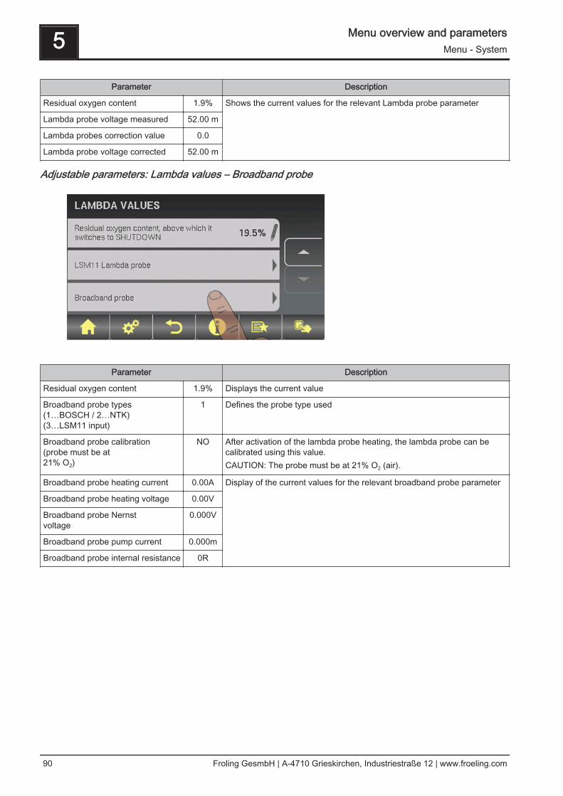
Parameter Description
Residual oxygen content 1.9% Shows the current values for the relevant Lambda probe parameter Lambda probe voltage measured 52.00 m
Lambda probes correction value 0.0
Lambda probe voltage corrected 52.00 m
Adjustable parameters: Lambda values – Broadband probe
Parameter Description
Residual oxygen content 1.9% Displays the current value
Broadband probe types(1…BOSCH / 2…NTK)(3…LSM11 input)
1 Defines the probe type used
Broadband probe calibration(probe must be at 21% O2)
NO After activation of the lambda probe heating, the lambda probe can becalibrated using this value.CAUTION: The probe must be at 21% O2 (air).
Broadband probe heating current 0.00A Display of the current values for the relevant broadband probe parameter
Broadband probe heating voltage 0.00V
Broadband probe Nernstvoltage
0.000V
Broadband probe pump current 0.000m
Broadband probe internal resistance 0R
5 Menu overview and parametersMenu - System
90 Froling GesmbH | A-4710 Grieskirchen, Industriestraße 12 | www.froeling.com

Determining the probe type
The type of probe installed must be determined before starting calibration. To this end,coloured stickers (BOSCH = blue, NTK= yellow) are affixed to the connection cable ofthe probe, as well as to each end of the extension cable.
BOSCH broadband probe NTK broadband probe
Once the type of probe has been determined, the parameters need to be adjusted ac‐cordingly in the controller.
Starting calibration❒ Set the type of probe used
➥ BOSCH = 1, NTK = 2For boilers with manual loading:❒ Open the insulated door
➥ Before starting calibration, the insulated door must be open for at least 3 - 4minutes so that the probe is warm enough and the boiler is sufficiently ventila‐ted
For boilers with automatic loading:❒ Boiler must be switched off
➥ Status "Boiler OFF" or "Standby"❒ Set "Lambda probe heating" parameter in the "Manual" - "Digital out-
puts" menu to "1"➥ Heat Lambda probe for at least 2 minutes
Calibrate probe:❒ Go to parameter "Broadband probe calibration"❒ Set parameter to "YES" and press the enter key
➥ Automatic calibration of the broadband probe begins➥ Once calibration is complete the parameter is automatically set to "NO" and the
broadband probe is ready for use
Menu overview and parameters 5Menu - System
Operating Instructions Lambdatronic S 3200 - Touch | B0840314_en 91

Adjustable parameters: General settings
Parameter Description
Very dry material (w < 15%) param‐eter adopt next line
NO If this parameter is set to "YES" and then the parameter “Adopt boilerstandard values” is set to “YES”, the parameters are automaticallyadjusted for very dry firewood.
Adopt boiler standard values NO If this parameter is set to "YES", the current parameters for the selectedboiler are set. After the values have been adopted the parameter jumps to"NO”.
Abort heating up --> ID fan off, closeair flaps
NO If this parameter is set to “YES”, the boiler heating up process can beaborted.NOTE: Criteria for “Off” status must be fulfilled.
Modem installed NO If the boiler has a modem for data transfer, this value must be set to"YES".
Memory cycle of data logger 5 s Do not change this value!This is the memory cycle used for saving data onto the data logger.
Send a line break when ASCII dataoutput on COM2
NO
COM 2 is used as a MODBUS inter‐face
NO YES:The COM 2 interface can be used for connection with a MODBUS (RTU /ASCII)NO:The COM 2 interface sends the most important boiler values every sec‐ond
MODBUS address 2 Adjustable parameters for MODBUS
MODBUS protocol(1 – RTU / 2 – ASCII)
1
Set hours since last maintenance to0
NO To reset the counter “Hours since last maintenance”, this parame‐ter must be set to "YES”. After the has been reset, the parameter jumps to"NO”.
5 Menu overview and parametersMenu - System
92 Froling GesmbH | A-4710 Grieskirchen, Industriestraße 12 | www.froeling.com
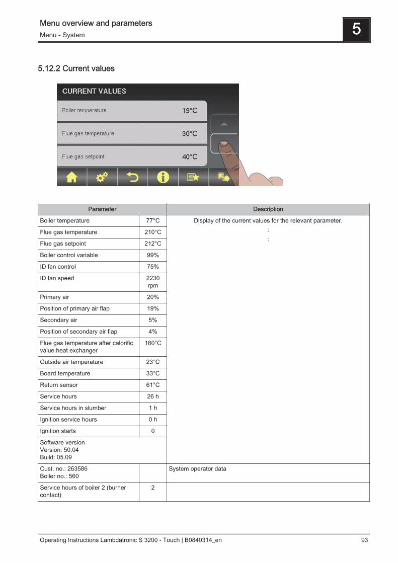
5.12.2 Current values
Parameter Description
Boiler temperature 77°C Display of the current values for the relevant parameter.::
Flue gas temperature 210°C
Flue gas setpoint 212°C
Boiler control variable 99%
ID fan control 75%
ID fan speed 2230rpm
Primary air 20%
Position of primary air flap 19%
Secondary air 5%
Position of secondary air flap 4%
Flue gas temperature after calorificvalue heat exchanger
160°C
Outside air temperature 23°C
Board temperature 33°C
Return sensor 61°C
Service hours 26 h
Service hours in slumber 1 h
Ignition service hours 0 h
Ignition starts 0
Software versionVersion: 50.04Build: 05.09
Cust. no.: 263586Boiler no.: 560
System operator data
Service hours of boiler 2 (burnercontact)
2
Menu overview and parameters 5Menu - System
Operating Instructions Lambdatronic S 3200 - Touch | B0840314_en 93

5.12.3 Sensors and pumps
Parameter Description
Which sensor is used for storage tank top
0.1 Setting the bus addresses of the sensors and pumps used⇨ See "Setting the module address" [page 20]The display of the parameters varies depending on the system set.Note the information on hydraulic systems in the "Lambdatronic S 3200energy systems" documents.
Which sensor is used for bottom storage tank
0.2
Which pump is used for the storage tank
0.1
Which sensor is used for the backup boiler
0.5
Which output is used for unloading standby boiler
Pump 1
Which sensor is used for the storage tank reference
0.2
Which pump is used for the solar collector
1.1
Which pump is used for the solar isolating valve
1.2
Which sensor is used for top DHW tank 1
0.3
Which sensor is used for solar refer‐ence DHW tank 1
0.4
Which sensor is used for bottom DHW tank 1
0.3
Which pump is used forDHW tank 1
0.2
5 Menu overview and parametersMenu - System
94 Froling GesmbH | A-4710 Grieskirchen, Industriestraße 12 | www.froeling.com

5.12.4 Display operating rights
Parameter Description
HEATING SYSTEM:
Allow access to heating circuit 1 ❒ Allocate access rights for changing heating circuit parameters to the indi‐vidual controls.Tap the respective heating circuit to activate the access rights of the heat‐ing circuit for the control. This is indicated when the “Confirm” icon ap‐pears.
:
Allow access to heating circuit 18 ❒
DHW TANK SYSTEM
Allow access to DHW tank 01 ❒ Allocate access rights for changing DHW tank parameters to the individualcontrols.Tap the respective boiler to activate the access rights of the DHW tank forthe control. This is indicated when the “Confirm” icon appears.
:
Allow access to DHW tank 08 ❒
STORAGE TANK SYSTEM:
Allow access to storage tank 01 ❒ Allocate access rights for changing storage tank parameters to the individ‐ual controls.Tap the respective storage tank to activate the access rights of the stor‐age tank for the control. This is indicated when the “Confirm” icon ap‐pears.
:
Allow access to storage tank 04 ❒
SOLAR SYSTEM:
Allow access to Solar 01 ❒ Allocate access rights for changing solar system parameters to the individ‐ual controls.Tap Solar 01 to activate the access rights of the solar system for the con‐trol. This is indicated when the “Confirm” icon appears.
Menu overview and parameters 5Menu - System
Operating Instructions Lambdatronic S 3200 - Touch | B0840314_en 95

Froeling Connect
Parameter Description
Password for boiler display -1 For connection via froeling-connect.com using a touch display, a separatepassword must be issued for each touch display. When using a touch dis‐play for a connection via froeling-connect.com, users have the same oper‐ating rights via the online portal as on the touch display.
Password for touch display with ad‐dress 1
-1
:
Password for touch display with ad‐dress 7
-1
5.12.5 Display allocation
Parameter Description
ROOM SENSOR CORRECTION:
Deviation of room sensor from touchdisplay with address 1
0°C If the current room temperature does not match the displayed/evaluatedvalue, this parameter can be used to adjust the evaluation of the roomtemperature sensor.:
Deviation of room sensor from touchdisplay with address 7
0°C
Deviation of room sensor from but‐ton display with address 1
0°C
:
5 Menu overview and parametersMenu - System
96 Froling GesmbH | A-4710 Grieskirchen, Industriestraße 12 | www.froeling.com

Parameter Description
Deviation of room sensor from but‐ton display with address 7
0°C
HEATING SYSTEM:
Touch display with address 1 is allo‐cated to the following heating circuit:
None Allocates the relevant control (address 1 - 7) to a particular heating circuit.WARNING! The parameters are set to "none" at the factory, so the heatingcircuit functions (room temperature sensor, party mode, setback mode, ...)are not possible on this control by default!
:
Touch display with address 7 is allo‐cated to the following heating circuit:
None
Button display with address 1 is al‐located to the following heating cir‐cuit:
None
:
Button display with address 7 is al‐located to the following heating cir‐cuit:
None
DHW TANK SYSTEM:
Touch display with address 1 is allo‐cated to the following DHW tank:
None Allocates the relevant control (address 1 - 7) to a particular DHW tank.WARNING! The parameters are set to "none" at the factory, so the hot wa‐ter functions (function key) are not possible on this control by default!:
Touch display with address 7 is allo‐cated to the following DHW tank:
None
Button display with address 1 is al‐located to the following DHW tank:
None
:
Button display with address 7 is al‐located to the following DHW tank:
None
5.12.6 System selection
⇨ See "Setting the system selection" [page 40]
Menu overview and parameters 5Menu - System
Operating Instructions Lambdatronic S 3200 - Touch | B0840314_en 97

5.13 Menu - Diagnostics
⇨ See "Navigation within the system menu" [page 31]
5.13.1 Error display
⇨ See "Troubleshooting" [page 104]
5.13.2 Error history
⇨ See "Troubleshooting" [page 104]
5 Menu overview and parametersMenu - Diagnostics
98 Froling GesmbH | A-4710 Grieskirchen, Industriestraße 12 | www.froeling.com

Any error messages still saved in the error history will be displayed with the relevanterror text and the time they occurred.
This is the time the error occurred.
This is the time the error was acknowledged.
This is the time the error was rectified.
5.13.3 Clear error history
Menu overview and parameters 5Menu - Diagnostics
Operating Instructions Lambdatronic S 3200 - Touch | B0840314_en 99

5.14 Menu - Display settings
⇨ See "Navigation within the system menu" [page 31]
5.14.1 General
Parameter Description
Adopt standard settings (all valuesare reset)
NO Adopting standard factory settings. This resets all parameters! After reset‐ting the parameters, the boiler must be reset; otherwise, boiler functioningis no longer guaranteed.
Room temperature 26.0°C Shows the current room temperature
Brightness 72 Light sensor’s evaluation of the current brightness in the room for adjust‐ing the backlight.
Maximum backlight 80% The brighter it is in the room, the more the background of the touch dis‐play is illuminated. This is where you can limit the maximum backlight.
Minimum backlight 20% The darker it is in the room, the less the background of the touch displayis illuminated. This is where you can set the minimum backlight.
Delay for screensaver (0 disablesthe screensaver)
60 s If the screen of the touch display is not touched within the set time, thescreensaver will activate and the control will go dark. To disable thescreensaver, set the delay time to “0”.
Module address Address0
This is where you can change the module address if it is incorrectly set. Module address 0: Boiler consoleModule address 1-7: respective RBG TouchOnce you have changed the module address, you will need to restart theboiler controller (switch main switch on boiler off and on).
5 Menu overview and parametersMenu - Display settings
100 Froling GesmbH | A-4710 Grieskirchen, Industriestraße 12 | www.froeling.com

Network settings
Parameter Description
Use DHCP ON IP address of touch control is automatically obtained from the network.
IP address 192.168.0.10 If the parameter “Use DHCP” is set to “NO”, the adjacent settings are re‐leased for editing.Subnet mask 255.255.255.0
Default gateway: 0.0.0.0
DNS server 0.0.0.0
5.14.2 Date / Time
⇨ See "Setting the date/time" [page 37]
Menu overview and parameters 5Menu - Display settings
Operating Instructions Lambdatronic S 3200 - Touch | B0840314_en 101

5.14.3 Software update / Service
⇨ See "Updating the software of the touch control" [page 26]
5 Menu overview and parametersMenu - Display settings
102 Froling GesmbH | A-4710 Grieskirchen, Industriestraße 12 | www.froeling.com

5.15 PWM / 0 - 10V settings
Description
▪ Normal pump (pump with load-tap changer)Set when a standard pump a switching valve with RC element is run at the respective output. When using a switchingvalve, set the minimum speed of the output to 100%. When a pump is used, it is controlled at the 230V output usingpulse packets.
▪ PDM / field pumpThere is a permanent power supply of 230V at the output for the high efficiency pump. The pump is controlled usingpulse duration modulation at the respective PDM output.
▪ PDM / Solar pumpHere again, the pump is controlled by means of pulse duration modulation at the respective PDM output. In this case,however, the characteristic line is inverted and can only be used for specially marked high efficiency solar pumps.
▪ PDM field Pump+valveThe signal for the field pump is emitted at the PDM output. If the signal exceeds 2%, the 230V output is switched on. Ifthe signal is below 2% for more than 4 minutes, the output is switched off again.
▪ 0 – 10V / field pump▪ 0 – 10V / solar pump▪ 0 – 10V field Pump+valve
The same functions that apply with PDM apply to the parameter values with 0-10V. The only difference is that insteadof pulse duration modulation, a 0-10V signal is used to control the pump.
Menu overview and parameters 5PWM / 0 - 10V settings
Operating Instructions Lambdatronic S 3200 - Touch | B0840314_en 103
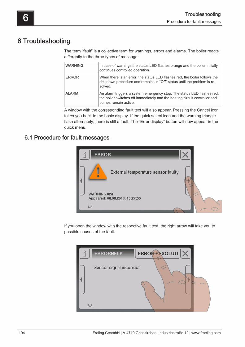
6 TroubleshootingThe term "fault" is a collective term for warnings, errors and alarms. The boiler reactsdifferently to the three types of message:
WARNING In case of warnings the status LED flashes orange and the boiler initiallycontinues controlled operation.
ERROR When there is an error, the status LED flashes red, the boiler follows theshutdown procedure and remains in “Off“ status until the problem is re‐solved.
ALARM An alarm triggers a system emergency stop. The status LED flashes red,the boiler switches off immediately and the heating circuit controller andpumps remain active.
A window with the corresponding fault text will also appear. Pressing the Cancel icontakes you back to the basic display. If the quick select icon and the warning triangleflash alternately, there is still a fault. The “Error display” button will now appear in thequick menu.
6.1 Procedure for fault messages
If you open the window with the respective fault text, the right arrow will take you topossible causes of the fault.
6 TroubleshootingProcedure for fault messages
104 Froling GesmbH | A-4710 Grieskirchen, Industriestraße 12 | www.froeling.com

Tapping “Solution” will also display action to be taken to resolve the problem. If thereare several options available, these will be listed one below the other.
Once the fault has been resolved, tap the Cancel icon to return to the basic display.
Troubleshooting 6Procedure for fault messages
Operating Instructions Lambdatronic S 3200 - Touch | B0840314_en 105

7 Setting protocolThe following tables show which heating components are allocated to the connections.Below the heating circuit number it notes the heating area, for which this heating cir‐cuit is used. The relevant connected unit should be noted next to the pumps or sen‐sors.Example: Module address = 2;
7 Setting protocol
106 Froling GesmbH | A-4710 Grieskirchen, Industriestraße 12 | www.froeling.com

Heating circuit module
Hydraulic module
Heating circuit module
Hydraulic module
Set module address: 2
First heating circuit: 07
Second heating circuit: 08
Heating circuit module Hydraulic module
Pump 2.1
Pump 2.2
Sensor 2.1
Sensor 2.2
Sensor 2.3
Sensor 2.4
Sensor 2.5
Sensor 2.6
Set modue address: 1
First heating circuit: 05
Second heating circuit: 06
Heating circuit module Hydraulic module
Pump 1.1
Pump 1.2
Sensor 1.1
Sensor 1.2
Sensor 1.3
Sensor 1.4
Sensor 1.5
Sensor 1.6
Final check
Bus cable correctly connected (see “Connecting the bus cable”))
Addressing correctly carried out and recorded
Jumper placed at the last module
Setting protocol 7
Operating Instructions Lambdatronic S 3200 - Touch | B0840314_en 107