Embed Size (px)
Citation preview

NASA Technical Memorandum 106600
, //" __j __
Laminated Thin Shell Structures
Subjected to Free Vibration ina Hygrothermal Environment
Pascal K. Gotsis and James D. Guptill
Lewis Research Center
Cleveland, Ohio
(NASA-TM-IO6600) LAMINATED THIN
SHELL STRUCTURES SUBJECTED TO FREE
VIBRATION IN A HYGROTHERMAL
ENVIRONMENT (NASA. Lewis Research
Center) 17 p
G3/39
N94-37456
Unclas
0017068
JULY 1994
National Aeronautics andSpace Administration
https://ntrs.nasa.gov/search.jsp?R=19940032948 2020-03-18T05:54:42+00:00Z
LAMINATED THIN SHELL STRUCTURES SUBJECTED TO FREE VIBRATION
IN A HYGROTHERMAL ENVIRONMENT
Pascal K. Gotsis and James D. Guptill
National Aeronautics and Space AdministrationLewis Research Center
Cleveland, Ohio 44135
SUMMARY
Parametric studies were performed to assess the effects of various parameters on the free-vibration behavior
(natural frequencies) of [_+0]2 angle-ply, fiber composite, thin shell structures in a hygrothermal environment.Knowledge of the natural frequencies of structures is important in considering their response to various kinds of
excitation, especially when structures and force systems are complex and when excitations are not periodic. Thethree-dimensional, finite element structural analysis computer code CSTEM was used in the Cray YMP
computer environment. The fiber composite shell was assumed to be cylindrical and made from T300 graphite
fibers embedded in an intermediate-modulus, high-strength matrix. The following parameters were investigated:
the length and the laminate thickness of the shell, the fiber orientation, the fiber volume fraction, the tempera-
ture profile through the thickness of the laminate, and laminates with different ply thicknesses. The results
indicate that the fiber orientation and the length of the laminated shell had significant effects on the natural
frequencies. The fiber volume fraction, the laminate thickness, and the temperature profile through the shell
thickness had weak effects on the natural frequencies. Finally, the laminates with different ply thicknesses had
an insignificant influence on the behavior of the vibrated laminated shell. Also, a single through-the-thickness,
eight-node, three-dimensional composite finite element analysis appears to be sufficient for investigating the
free-vibration behavior of thin, composite, angle-ply shell structures.
INTRODUCTION
High-speed flight vehicles require new materials able to withstand hostile environments (moisture and
temperature) at speeds that are a multiple of the speed of sound and improved computational approaches to
designing them. The new materials, known as elevated-temperature composites, have high strength, are light in
weight, and can be tailored for the required performance. These materials are already finding applications and
acceptance in aircraft frame and engine structures. Cost-effective usage of elevated-temperature composite
materials requires new ideas and innovative concepts in material selection and structure fabrication in order todesign them for durability by properly accounting for the many failure mechanisms inherent in composites. Theinfluence of hostile environments, nonlinear material, and structural behavior and the coupling between
responses induced by various loads require sophisticated analysis methods.
A stand-alone, multidisciplinary computer code, CSTEM (Coupled Structural, Thermal, and Electromagnetic
Analysis and Tailoring) (refs. 1 to 7), has been developed by integrating three-dimensional, finite element,structural and stress analysis methods with several single-discipline codes including those for integrated
composite mechanics (refs. 8 and 9). The advantage of performing finite element analysis using three-dimensional brick elements is that the temperature gradient as well as the stress gradient can be varied through
the thickness of the laminated structure, in contrast to two-dimensional plate elements.
This report presents parametric studies that used the CSTEM computer code to assess the effects of various
parameters on an aircraft engine composite shell structure subjected to free vibration at elevated temperatures.Knowledge of the natural frequencies of structures is important in considering their response to various kinds of
excitation, especially when structures and force systems are complex and when excitations are not periodic
(refs.10 and 11). The structure studied is a thin, cylindrical composite shell. The composite is to be made from
[+_0]2 angle-ply laminates containing plies with uniform thickness. Parametric studies were performed toexamine the effects on the natural frequencies of parameters, such as the length and laminate thickness of the
shell, the temperature profile through the thickness of the laminate, the fiber volume fraction, the fiber
orientation, and laminates with different ply thicknesses.
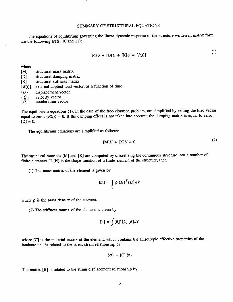
BRIEF DESCRIPTION OF SIMULATION PROCEDURE
The general-purpose computer code CSTEM (ref. 4) computationaUy simulates the coupled multidisciplinarystructural, heat transfer, vibration, acoustic, and electromagnetic behavior of elevated-temperature, layered,
multimaterial composite structures. All the disciplines are coupled for nonlinear geometrical, material, loading,and environmental effects. CSTEM is based on a modular structure (fig. 1) and is accessed by the user through
its executive module. The structural response can be predicted at all the composite scales including constituent
(fiber and matrix) and ply level.
The composite mechanics is simulated with the ICAN (Integrated Composite Analyzer) module (refs. 8
and 9), which performs, among others, through-the-thickness point stress analysis. The micromechanics
equations embedded in ICAN include the effects of temperature and moisture. ICAN simulates the behavior of
polymer composites from the constituent material level to the laminate level, as depicted in figures 2 and 3.ICAN includes a resident material property data bank for commercially available fiber and matrix constituent
materials at room temperature. The user needs only to specify a code name for the desired constituent materials
(rather than having to manually input all the properties) in the CSTEM input.
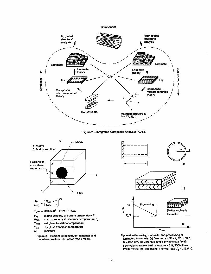
The procedure for computationally simulating composite structures is shown in figure 2 and consists of four
parts: the constituents, the synthesis, the finite element structural analysis, and the decomposition. For a detaileddescription of these four parts see references 8 and 9. The computational procedure steps are as follows:
(1) Constituents. The material properties of the matrix in any operational temperature and moisture
conditions are updated by using the constitutive equation depicted in figure 3. The fiber properties were
assumed to be unchanged by the hygrothermal conditions.
(2) Synthesis. The thermal and mechanical properties of the plies are synthesized from the mechanical
properties of the fibers and matrix by using composite micromechanics theory. The extensional stiffness matrixA, the coupling stiffness matrix B, and the bending stiffness matrix D are computed by using laminate theoryand the thermal and mechanical effective laminate engineering properties (ref. 12).
(3) Finite element analysis. The finite element analysis is performed at the composite structural level, and
among others, the resulting forces and moments are computed at each node of the finite element mesh. Because
ICAN performs through-the-thickness point stress analysis, steps (1) and (2) and the upcoming step (4) are
performed at each individual node of the finite element mesh.
(4) Decomposition. The stresses and strains in each ply are computed by using laminate theory. The stressesand strains within the matrix and the fibers for each ply are computed by using composite micromechanics.
The CSTEM code is written in FORTRAN programming language and is installed on the NASA Lewis
Cray YMP computer system.
2
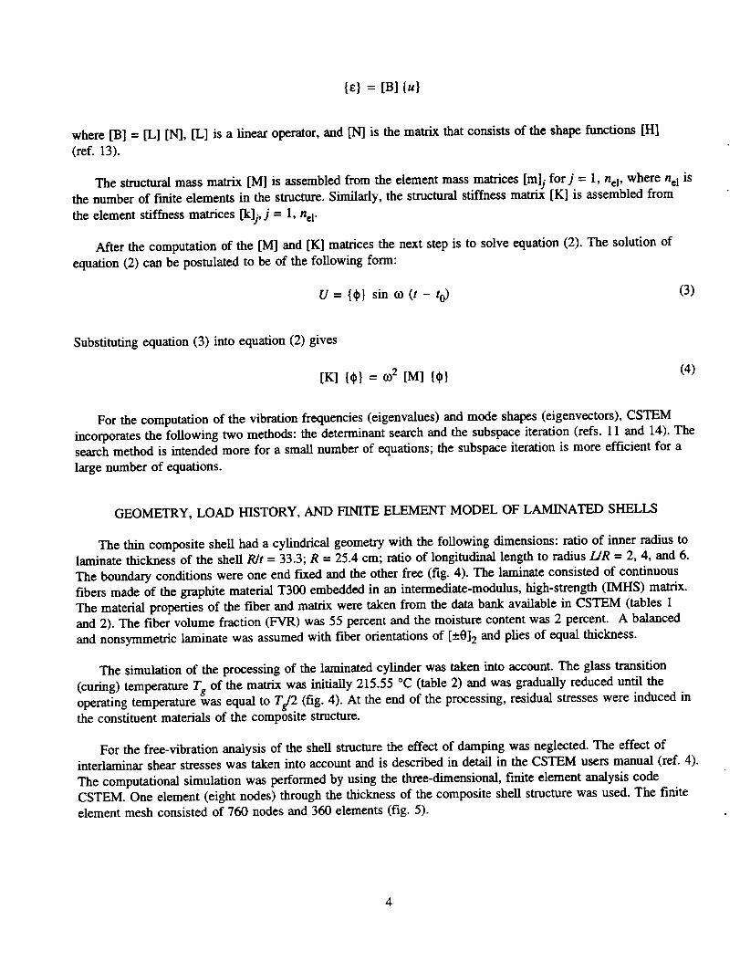
SUMMARYOFSTRUCTURALEQUATIONS
The equations of equilibrium governing the linear dynamic response of the structure written in matrix form
are the following (refs. 10 and 11):
[M]0 + [D]U + [K]U = {R(t)l(1)
where
[M][D][K]{R(t)}{U}{t)}{0}
structural mass matrix
structural damping matrixstructural stiffness matrix
external applied load vector, as a function of time
displacement vector
velocity vectoracceleration vector
The equilibrium equations (1), in the case of the free-vibration problem, are simplified by setting the load vector
equal to zero, {R(t)} = 0. If the damping effect is not taken into account, the damping matrix is equal to zero,
[D]= 0.
The equilibrium equations are simplified as follows:
[M]0+ [K]U=0 (2)
The structural matrices [M] and [K] are computed by discretizing the continuous structure into a number of
finite elements. If [H] is the shape function of a finite element of the structure, then
(1) The mass matrix of the element is given by
[m] = f p {n}r{n}dV
V
where p is the mass density of the element.
(2) The stiffness matrix of the element is given by
tk] = fiB]tic] [B]dV1;
where [C] is the material matrix of the element, which contains the anisotropic effective properties of the
laminate and is related to the stress-strain relationship by
{c} = [c] {E}
The matrix [B] is related to the strain displacement relationship by
{e} = [B]lu}
where [B] = [L] [N], [L] is a linear operator, and [N] is the matrix that consists of the shape functions [H]
(ref. 13).
The structural mass matrix [M] is assembled from the element mass matrices [m]j for j = 1, nel, where nel is
the number of finite elements in the structure. Similarly, the structural stiffness matrix [K] is assembled from
the element stiffness matrices [k]j, j = 1, nel.
After the computation of the [M] and [K] matrices the next step is to solve equation (2). The solution of
equation (2) can be postulated to be of the following form:
U = {¢} sin co (t - to) (3)
Substituting equation (3) into equation (2) gives
[K] {0} =_2 [M] 10}(4)
For the computation of the vibration frequencies (eigenvalues) and mode shapes (eigenvectors), CSTEM
incorporates the following two methods: the determinant search and the subspace iteration (refs. 11 and 14). Thesearch method is intended more for a small number of equations; the subspace iteration is more efficient for a
large number of equations.
GEOMETRY, LOAD HISTORY, AND FINITE ELEMENT MODEL OF LAMINATED SHELLS
The thin composite shell had a cylindrical geometry with the following dimensions: ratio of inner radius tolaminate thickness of the shell R/t = 33.3; R = 25.4 cm; ratio of longitudinal length to radius L/R = 2, 4, and 6.
The boundary conditions were one end fixed and the other free (fig. 4). The laminate consisted of continuous
fibers made of the graphite material T300 embedded in an intermediate-modulus, high-strength (IMHS) matrix.
The material properties of the fiber and matrix were taken from the data bank available in CSTEM (tables 1and 2). The fiber volume fraction (FVR) was 55 percent and the moisture content was 2 percent. A balanced
and nonsymmetric laminate was assumed with fiber orientations of [--.0]2 and plies of equal thickness.
The simulation of the processing of the laminated cylinder was taken into account. The glass transition
(curing) temperature Tg of the matrix was initially 215.55 °C (table 2) and was gradually reduced until the
operating temperature was equal to Tg/2 (fig. 4). At the end of the processing, residual stresses were induced inthe constituent materials of the composite structure.
For the free-vibration analysis of the shell structure the effect of damping was neglected. The effect ofinterlaminar shear stresses was taken into account and is described in detail in the CSTEM users manual (ref. 4).
The computational simulation was performed by using the three-dimensional, finite dement analysis codeCSTEM. One element (eight nodes) through the thickness of the composite shell structure was used. The finite
element mesh consisted of 760 nodes and 360 elements (fig. 5).
4
RESULTSANDDISCUSSION
In thissectiontheresultsobtainedfor thedifferent [--.0]2 angle-ply composite shells are presented and
discussed. The parameters investigated include
(1) Effects of fiber orientation
(2) Effects of shell length
(3) Effects of laminate thickness
(4) Effects of temperature
(5) Effects of fiber volume fraction
(6) Effects of different ply thicknesses
Effects of Shell Length
The influence of shell length in conjunction with ply angle 0 was examined to study the free-vibration
behavior of the composite shell. Results obtained for natural frequencies and mode shapes are summarized here.
Natural frequencies.--Three thin composite shells with length ratios/dR of 2, 4, and 6 were examined. The
computed values of the first natural frequency are plotted versus 0 and the three L/R ratios in figure 6. The com-
puted values are normalized with respect to the maximum frequency of 554.9 Hz. Correspondingly, thecomputed values of the second natural frequency are normalized with respect to the maximum frequency of
609.6 Hz and are plotted in figure 7. Finally, the computed values of the third natural frequency are normalized
with respect to the maximum frequency of 871.8 Hz and are shown in figure 8. The following conclusions were
reached:
(1) For all LIR the natural frequencies increased for 0 ° < 0 < 22.5 ° and decreased for 22.5 ° < 0 < 90 °. The
maximum frequencies (first, second, and third) occurred at 0 = 22.5 °.
(2) The shorter the shell, the higher the frequencies, as expected because shorter shells are stiffer than
longer shells.
(3) The percentage differences of the natural frequencies between the short (/dR = 2) and long (/dR = 6)
shells for the different ply angles are significant (table 3) and depend on the ply angle.
Mode Shapes.--The behaviors of the mode shapes of the composite shell with/dR = 6 and R/t = 33.3 for
the fn'st three frequencies are presented graphically as follows:
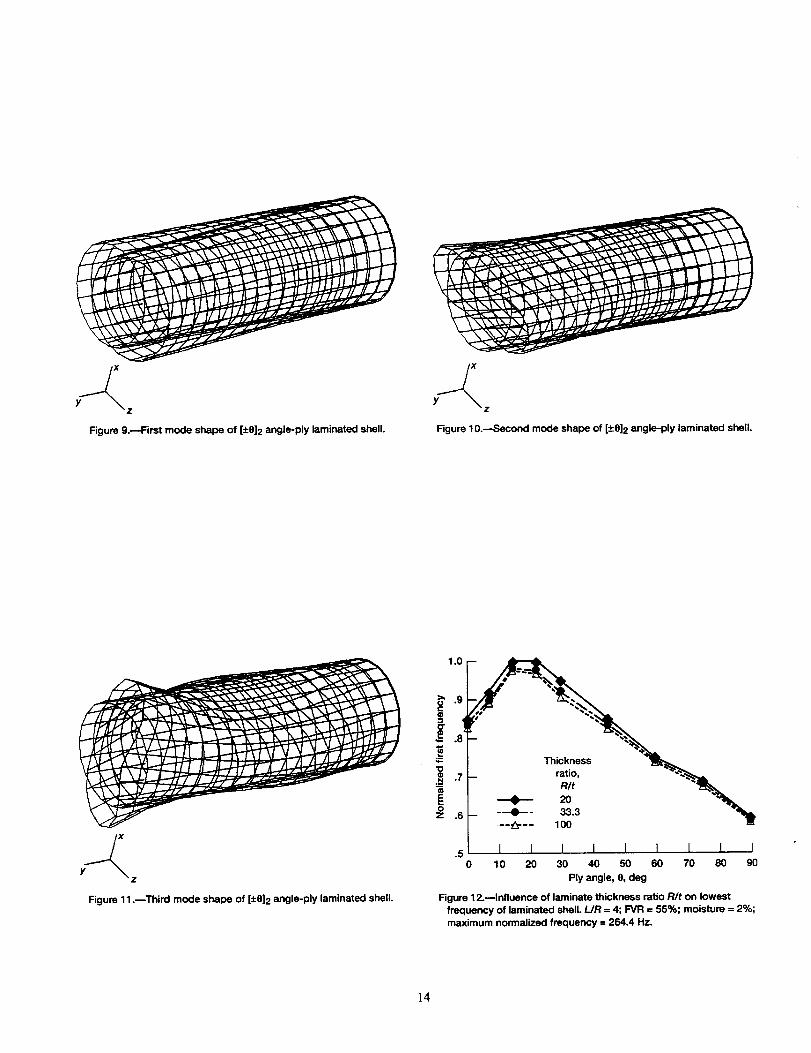
(1) First (lowest) frequency: The mode shape (fig. 9) is primarily bending, indicating that the shell behaveslike a cantilever beam.
(2) Second frequency: The mode shape (fig. 10) is a combination of torsional and breathing (or radial)modes.
(3) Third frequency: The mode shape (fig. 11) is a combination of torsional, breathing (or radial), and axial
(or longitudinal) modes.
These mode shapes are summarized in table 4 for 0 ° _<0 < 90 °.
Effectsof Laminate Thickness
The influence of laminate thickness of the thin composite shell versus the ply angle 0 for laminate thickness
ratios R/t of 20, 33.3, and 10Ois presented in figure 12. The computed values are normalized with respect to the
maximum frequency of 264.4 Hz. The following conclusions were reached from figure 12:
(1) For all R/t the first natural frequencies increased for 0 ° _<O -< 15 ° and decreased for 15° -< 0 < 90 °. The
maximum frequency occurred at 0 = 15°.
(2) The thicker the composite shell, the higher the values of the natural frequencies. Thus, thick composite
shells (R/t = 20) had the highest frequencies, and thin composite shells (R/t = 100) had the lowest frequencies.
The frequencies maximized at O = 15°.
(3) The percentage difference of the natural frequencies between the thick laminated shell (R/t = 20) and thethin laminated shell (R/t = 100) was relatively small (table 5).
Therefore, the laminate thickness ratio R/t had only a small effect on the first natural frequencies of the
laminated shell.
Effects of Temperature
The effects of temperature and moisture profiles through the laminate thickness on the free vibration in
conjunction with ply angle 0 were examined. Three temperature profiles with uniform moisture (2 percent) were
considered. The first profile was uniform with temperature equal to room temperature (21 °C), the second
profile was also uniform with temperature equal to Tg/2 (107.7 °C), and the third profile varified linearly, with
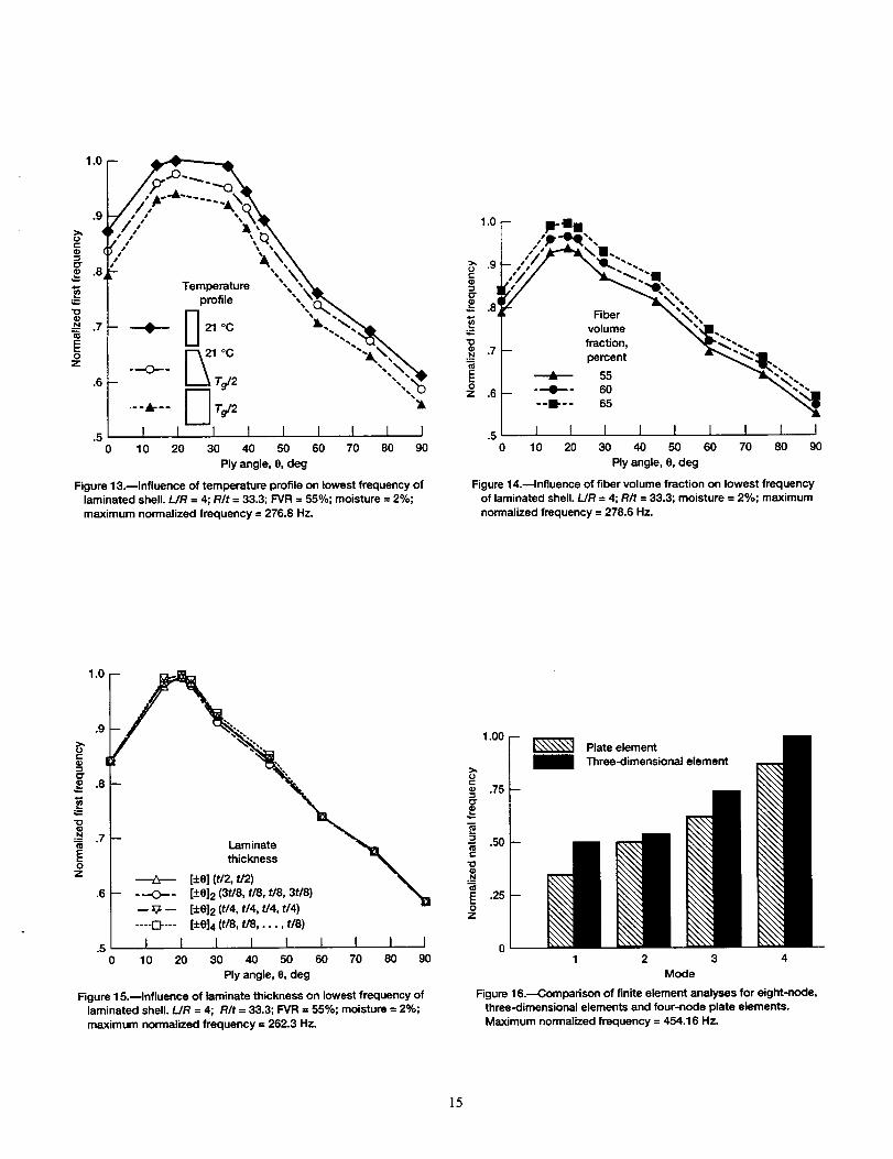
temperature equal to Tg/2 at the inner surface and room temperature at the outer surface of the composite shell.The length ratio LIR was 4 and the laminate thickness ratio R/t was 33.3. The computed values of the firstnatural frequency, normalized with respect to the maximum value of 276.8 Hz, are plotted versus ply angle 0
for three temperature profiles in figure 13. The following observations were made:
(1) For all temperature profiles the natural frequencies increased for 0 ° _<0 _<20 ° and decreased for
20 ° < 0 < 90 °. The frequency peaked at 0 = 20 °.
(2) The room-temperature composite shell had the highest frequencies, followed by the composite shell with
the linear profile and finally the composite shell with the uniform temperature equal to Tg/2.
(3) The percentage difference in natural frequency between the uniform room-temperature prof'des and Ts,/2
was low (table 5) and was almost independent of 0.
Therefore, the temperature profile had little effect on the natural frequencies of the composite shell throughout
the angle-ply range.
Effects of Fiber Volume Fraction
The effects of fiber volume fraction in conjunction with ply angle 0 on the free-vibration behavior of the
composite shell were evaluated. Three fiber volume fractions were examined: 55, 60, and 65 percent. The lengthratio L/R was 4 and the laminate thickness ratio R/t was 33.3. The computed values of the first natural
frequency,normalizedwith respect to the maximum value of 278.6 Hz, are plotted versus ply angle 0 for thevarious fiber volume fractions in figure 14. The following conclusions were reached:
(1) For all fiber volume fractions the natural frequencies increased for 0 ° < 0 _<20 ° and decreased for
20 ° < 0 <- 90 °. The maximum natural frequency occurred at 0 = 20 °, which was the same for all the cases
investigated.
(2) The composite shell with 65-percent fiber volume fraction had higher frequencies than the shell with the
60-percent fiber volume fraction, which had higher frequencies than the shell with 55-percent fiber volume
fraction.
(3) The percentage difference in the natural frequencies between the two laminates with fiber volume
fractions of 65 and 55 was very low (table 5).
Therefore, the fiber volume fraction had little effect on the natural frequencies of the composite shell.
Effects of Ply Thickness
The effects of laminates with various ply thicknesses in conjunction with ply angle 0 on the natural
frequencies of the composite shell were examined. The length ratio L/R was 4, the laminate thickness ratio R/twas 33.3, and the fiber volume fraction was 55 percent. Four laminated shells with different ply thicknesses andthe same laminate thickness t were examined: (1) a [±0] angle-ply laminate with equal ply thicknesses (t12, t/2),
(2) a [±0] 2 angle-ply laminate with nonuniform ply thicknesses (3t/8, t18, t18, 3t/8), (3) a [__.0]2 angle-plylaminate with uniform ply thicknesses (t14, t14, t14, t14), and (4) a [±0] 4 angle-ply laminate with equal ply
thicknesses (t/8, t18..... t18). The computed values for the first natural frequencies of these examined laminates are
plotted versus 0 in figure 15. The following conclusions were reached:
(1) The natural frequencies increased for 0 ° -< 0 < 20 °, decreased for 20 ° - 0 - 90 °, and peaked at 0 = 20 °.
(2) The laminas with different ply thicknesses had an insignificant effect on the natural frequencies of the
thin composite shells.
FINITE ELEMENT ANALYSIS USING EIGHT-NODE, THREE-DIMENSIONAL
ELEMENTS VERSUS FOUR-NODE PLATE ELEMENTS
The behaviors of the shell structure subjected to free vibration using eight-node, three-dimensional elements
versus four-node plate elements were compared. The geometry of the laminated structure consisted of a cylinder
with length equal to 40 in., an inner radius equal to 10 in., and uniform laminate thickness equal to 0.3 in. The
laminate consisted of graphite T300 fibers and a high-strength IMHS matrix. The fiber volume fraction was
55 percent, the ply angle was [0/90] 2, and the moisture was 2 percent. The laminated structure had an initial
temperature of 215.55 °C that was gradually reduced to the operational temperature of 108 °C. The natural
frequencies were computed by using the MHOST computer code (ref. 15) in conjunction with plate element 75,normalized, and plotted in figure 16. The frequencies obtained with the eight-node, three-dimensional elements
were higher than the frequencies obtained with the four-node plate elements. The reason is that the eight-node
element is stiffer than the plate element and therefore the natural frequencies are higher.
In order to improve the accuracy of the computational simulation of laminated, thin shell structures
subjected to free vibration, it is recommended that a 20-node brick element be used or that an eight-node brickelement be used and the mesh refined.
SUMMARY OF RESULTS
The free vibration of thin composite shell structures in a hygrothermal environment was computationally
simulated by using the CSTEM three-dimensional, finite element analysis computer code. The simulation
included the effects of parameters such as ply angle, shell length and laminate thickness, temperature, and fibervolume fraction on the free-vibration behavior of the composite shells. The important results are summarized as
follows:
(1) The ply angle and the length of the laminated shell significantly influenced the free-vibration (frequen-
cies and mode shapes) behavior of the composite shells.
(2) The fiber volume fraction, the laminate thickness, and the temperature profile through the laminate
thickness had little effect on the free-vibration behavior of the composite shells.
(3) The laminates with different ply thicknesses had an insignificant effect on the free-vibration behavior of
the composite shells.
(4) A single through-the-thickness, eight-node, three-dimensional-composite finite element analysis appears
to be sufficient for investigating the free-vibration behavior of thin, composite, angle-ply cylindrical shells.
ACKNOWLEDGMENT
The authors would like to thank Dr. Clmstos C. Chamis for his helpful discussion of the present paper.
REFERENCES
1. Gotsis, P.K.; and Guptill, J.D.: Buckling Analysis of Laminated Thin Shells in a Hot Environment. NASA
TM-106302, 1993.
2. Gotsis, P.K.; and Guptill, J.D.: Free Vibration of Fiber Composite Thin Shells in a Hot Environment.
Accepted for publication in the Journal of Reinforced Plastic and Composites in April 1994.
3. Gotsis, P.K.; and Guptill, J.D.: Fiber Composite Thin Shells Subjected to Thermal Buckling Loads. Accepted
for publication in the International Journal of Computers and Structures in June 1994.
4. Hartle, M. : CSTEM User's Manual. General Electric Company, Cincinnati, OH, 1990.
5. Chamis, C.C.; and Singhal, S.N.: Coupled Multi-Disciplinary Simulation of Composite Engine Structures in
Propulsion Environment. NASA TM-105575, 1992.
6. Singhal, S.N.; Murthy, P.L.N.; and Chamis, C.C.: Coupled Multi-Disciplinary Composites BehaviorSimulation. NASA TM-106011, 1993.
7. Singhal,S.N., et al.: Computational Simulation of Acoustic Fatigue for Hot Composite Structures. NASA
TM-104379, 1991.
8. Murthy, P.L.N.; and Chamis, C.C.: Integrated Composite Analyzer (ICAN)---User's and Programmer's
Manual. NASA TP-2515, 1986.
9. Chamis, C.C.: Simplified Composite Micromechanics Equations for Hygral, Thermal, and Mechanical
Properties. NASA TM-83320, 1987.
10. Hurry, W.C.; and Rubinstein, M.F.: Dynamics of Structures. Prentice-Hall, Inc., 1964.
11. Meirovitch, L.: Analytical Methods in Vibrations. MacMillan Company, 1967.
12. Whitney, J.M.; Daniel, I.M.; and Pipes, R.B.: Experimental Mechanics of Fiber Reinforced CompositeMaterials. The Society for Experimental Mechanics, Brooldield Center, CT, 1984.
13. Zienkiewicz, O.C.: The Finite Element Method. Third ed. McGraw-Hill Co., 1977.
14. Bathe, K.J.: Finite Element Procedures in Engineering Analysis. Prentice-Hall, 1982.
15. Nakazawa, S.: The MHOST Finite Element Program: 3-D Inelastic Analysis Methods for Hot Section
Components, Volume I. Theoretical Manual. NASA CR-182205, 1991.
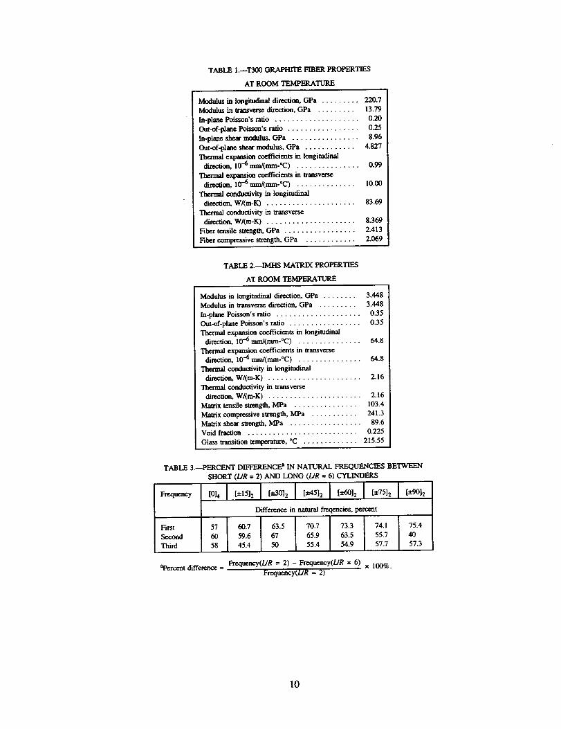
TABLE I.--T3(_ GRAPHrrE FIBER PROPERTIES
AT ROOM TEMPERATURE
Modulus in longitudinal direction, GPa ......... 220.7
Modulus in transvease direction, GPa ......... 13.79
In-plane Poisson's ratio .................... 0.20
Out-of-plane Poisson's ratio ................. 0.25
In-plane shem- modulus, GPa ................ 8.96
Out-of-plane shear modulus, GPa ............ 4.827
Thermal expansion coefficients in longitudinal
di_on, 10 -6 mm/(mm-°C) ............... 0.99
Thermal expansion coefficients in transverse
direction, 10 .=6 ml'n/(mm:C) .............. 10.00
Thermal conductivity in longitudinal
direction, W/(m-K) ..................... 83.69
Thermal conductivity in transverse
_on, W/(m-K) ..................... 8.369
Fiber tensile strength, GPa ................. 2.413
Fiber compressive strength, GPa ............ 2.069
TABLE 2.--IMHS MATRIX PROPERTIES
AT ROOM TEMPERATURE
Modulus in longitudinaldirection,OPa ........ 3.448
Modulus in transversedirection,GPa ......... 3.448
In-plm_ePoisson'sratio .................... 0.35
Out-of-planePoisson'sratio ................. 0.35
Thermal expansion coefficients in longitudinal
direction, 10 -6 mm/(mm-°C) ............... 64.8
Thermal expansion coefficients in transverse
direction, 10 --6 mm/(mm-°C) ............... 64.8
Thermal conductivity in longitudinal
direction, W/(m-K) ...................... 2.16
Thermal conductivity in transverse
direction, W/(m-K) ...................... 2.16
Matrix tensile strength, MPa ............... 103.4
Matrix compressive strength, MPa ........... 241.3
Matrix she_ strength,MPa ................. 89.6
Void fraction .......................... 0.225
Glass transition tcmlaeramm, °C ............. 215.55
Frequency
TABLE 3. PERCENT DIFFERENCE a IN NATURAL FREQUENCIES BETWEEN
SHORT (/JR = 2) AND LONG (/JR = 6) CYLINDERS
[0'41 [:1:1512 [ [:1r'3012 I t 512 I I [±75121 [_7°12
Difference in natural freqencies, percent
First
Second
Third
57 60.7 63.5 70.7 73.3 74.1 75.4
60 59.6 67 65.9 63.5 55.7 40
58 45.4 50 55.4 54.9 57.7 57.3
aPercent difference - Fa'equency(L/R = 2) - Frequency(L/R = 6) x 100%.
Frequency(L/R = 2)
10
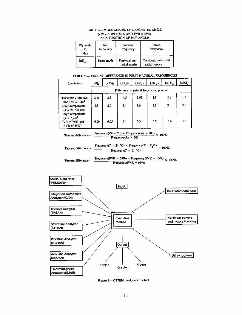
TABLE 4.--MODE SHAPES OF LAMINATED SHELL
(UR = 6, R/t = 33.3, AND FVR = 55%)AS A FUNCTION OF PLY ANGLE
Ply angle, First
O, frequency
deg
[_*0]2 Beam mode
Second
frequency
Torsional and
radial modes
Third
frequency
Torsional, axial, and
radial modes
TABLE 5.--PERCENT DIFFERENCE IN FIRST NATURAL FREQUENCIES
Thick(RIt = 20) and
thin(R/t= 100)_Room-temperature
(T = 21 °C) and
high-temperature
(T = TE_)bFVR of 65% and
FVR of 55% ¢
Difference in natural freqencies, tin'cent
[x-O0]2
2.35 2.5 4.5 9.62 ! .8 0.8 1.2
3.8 2.5 3.1 3.6 3.3 3 3.5
6._ 6._ 6.1 6.3 6.2 5.4 5.8
aPercent difference = Frequency(R/t = 20) - Frequency(R/t = 1(3(3) x 100%.Frequency(R/t = 20)
Frequency(T = 21 °C) - Frequency(T = Tg/2) x 100%.
Frequency(T = 21 °C)bpercent difference =
c'Percent difference = Frequency(FVR = 65%) - Frequency(FVR = 55%) x 100%.Fre,quency(FVR = 65%)
Model Generator I
, , _ /I Dedicated data base [
[Integrated Composite I _ / = i
I (THEAN) _ ""'4" "l
• l x u,,ve I I"o."n--rso've Imodule I and history tracking [
IAcoustic Analyzer I / / \ _l .. . ,
[ (ACOAN) ]// Table_/s _Vidc os "[ Utlhty routines ]
Electromagnetic Gra )hs
Analyzer (EMAN)
Figure 1 .--CSTEM modular structure.
11
Component
¢o
C
O3
/IIIt\
To global _ From global
structural _ structuralanalysis # _ analysis
/ Laminate _ ____i/ pN_._'._._ Laminate \
A Laminate _ _ Laminate .L]
Composite _ _ b / Composite ii_ micromechanics\ micromechanics I M _" theory
theory p_-- T //
\\
\Constituents
/t /
/Materials properties /P = f(T, M, t) /
_..f//
\\
/=E0
/ °Q
i
Figure 2.---Integrated Composite Analyzer (ICAN).
3 /_ MatrixA: Matrix /B: Matrix and fiber f
H' //
Regions ofI AconstituentE
materials --_.
\\
X_ Rber
H Q(a)
IX\X\\\ L,,'fL,,C"YI //////I XXX\\\ L_ (b)
PM I TGW - T ]1/2
_o = tT--_D-_J
TGW = (0.005 M 2 - 0.1M + 1)TGD
PM matrix property at current temperature TPMO matrix property at reference temperature TO
TGW wet glass transition temperature
TGD dry glass transition temperatureM moisture
Figure 3._Regions of constituent materials andnonlinear meterial characterization model.
Tg/2
Processing i
(c)
Time
Figure 4.--Geometry, materials, and processing oflaminated thin shells. (a) Geometry:. UR = 4; R/t = 33.3;R = 25.4 cm. (b) Materials: angle-ply laminate [0/-6]2;fiber volume ratio -- 55%; moisture = 2%; T300 fibers;
IMHS matrix. (c) Processing. Thermal load Tg = 215.5 °C.
12
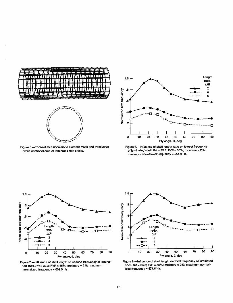
Figure 5.--Three-dimensional finite element mesh and transversecross-sectional area of laminated thin shells.
1.0
i "6A
.41
o "2E
_ _ Length_ ratio,
/- \ L/R_ _ 2
- "'_ ...... _ ..... -o- ..... -D
I I I I I I I I0 10 20 30 40 50 60 70 80
Ply angle, 0, deg
Figure 6.--Influence of shell length ratio on lowest frequencyof laminated shell. R/t = 33.3; F-VR= 55%; moisture = 2%;maximum normalized frequency = 554.9 Hz.
I90
i"- .6 ""4t,
a ,.z" s"" Length ", _._ _ ._(p..--_-O• / ratio, L_'- -El- ........... -_ ..... -O
N F]" L/R
.2-- _ 2Z ---0--- 4
--_-- 6I I I I I I I I I
0 10 20 30 40 50 60 70 80 90
Ply angle, 0, deg
Figure 7._lnfluence of shell length on second frequency of lamina-ted shell. R/t = 33.3; FVR = 55%; moisture = 2%; maximumnormalized frequency = 609.6 Hz.
1.0
O"
.6'
=-.Jt" O--m " "'e....
IZ /" Length _"O-,/' ratio, " .... 0 ...... 0 ...... U
_" LIR-- _ 2
---4_'" 4
-TE_-- i 6 I I I I I I I1 0 20 30 40 50 60 70 80 90
Ply angle, O,deg
Figure 8._lnfluence of shell length on third frequency of laminatedshell. R/t = 33.3; FVR = 55%; moisture = 2%; maximum normal-ized frequency = 871.8 Hz.
13
Y_z
Figure 9.---First mode shape of [-+6]2 angle-ply laminated shell.
Y_z
Figure 10._Second mode shape of [-+0]2 angle-ply laminated shell.
Y_z
Figure 11 .mThird mode shape of [-+0]2 angle-ply laminated shell.
_- Thickness_ _ ratio, _-_
o .6 - "'-=-" 33.3 -_--_'-- 100 m
.5 I I I I I I [ I I
0 10 20 30 40 50 60 70 80 90
Ply angle, O, deg
Figure 12.mlnfluence of laminate thickness ratio R/t on lowest
frequency of laminated shell. L/R = 4; FVR = 55%; moisture = 2%;
maximum normalized frequency -- 264.4 Hz.
14
1.0
.9
t..)t--¢= q
_r
p .8
"O
.7
OZ
.6
.50
Temperature ",, ,,_
N 21---o-- I\
"'&"" U Tg/2
I I I I I I I I I10 20 30 40 50 60 70 80 90
Ply angle, e, deg
Figure 13.--Influence of temperature profile on lowest frequency oflaminated shell. L/R -- 4; R/t = 33.3; FVR = 55%; moisture = 2%;maximum normalized frequency = 276.8 Hz.
(9
"O
EO
Z
_.0[- p-e,,
1l,_/,"/ _.='_. I,C'Y -_',o,_,
' elDer _M',volume "_..
__ fraction, _L.,_ ,. ,.7- pe ent
55.6 -- ---O--- 60 _!1
--i-- 65
.5 I I I I I I I I I0 10 20 30 40 50 60 70 80 90
Ply angle, e, deg
Figure 14.---Influence of fiber volume fraction on lowest frequencyof laminated shell. LIR = 4; RIt = 33.3; moisture = 2%; maximumnormalized frequency = 278.6 Hz.
1.0
.7 --
thickness[_+6](t/2, t/2)
.6 -- ---0--- [-+012(3tl8, t/8, t18, 3t/8) _=--_-- [_+0]2(t/4, t/4, t/4, t/4)
.... [_---- [+6]4 (t/8, t18..... t18)
.5 I t I t I I I i I0 10 20 30 40 50 60 70 80 90
Ply angle, 8, deg
Figure 15._lnfluence of laminate thickness on lowest frequency oflaminated shell. L/R = 4; RIt = 33.3; FVR = 55%; moisture = 2%;maximum normalized frequency = 262.3 Hz.
.9
¢J
¢D
O"
.8
"10
._N
EO
Z
1.00
(J
® .75-iO"
_ .50e..
N
g .2_@
Plate element
i Three-dimensional element
01 2 3 4
Mode
Figure 16.---Comparison of finite element analyses for eight-node,three-dimensional elements and four-node plate elements.Maximum normalized frequency = 454.16 Hz.
15
Form ApprovedREPORT DOCUMENTATION PAGE OMBNo. 0704-0188
Public repotting burden for this collection of information is estimated to average 1 hour per response, including the time for rewewing instructions, searching existing data sources,gathering and maintaining the data needed, and completing and reviewing the collection of information. Send comments regarding this burden estimate or any other aspect of thiscollection of information, including suggestions for reducing this burden, to Washington Headquarters Services, Directorate for Information Operations and Reports, 1215 JeffersonDavis Highway, Suite 1204, Arlington, VA 22202-4302, and to the Office of Management and Budget, Paperwork Reduction Project (0704-0188). Washington. DC 20503.
1. AGENCY USE ONLY (Leave blank) 2. REPORT DATE 3. REPORT TYPE AND DATES COVERED
July 1993 Technical Memorandum
4. TITLE AND SUBTITLE 5. FUNDING NUMBERS
Laminated Thin Shell Structures Subjected to Free Vibration in a Hygrothermal
Environment
S. AUTHOR(S)
Pascal K. Gotsis and James D. Guptill
7. PERFORMING ORGANIZATION NAME(S) AND ADDRESS(ES)
National Aeronautics and Space Administration
Lewis Research Center
Cleveland, Ohio 44135-3191
9. SPONSORING/MONITORING AGENCY NAME(S) AND ADDRESS(ES)
National Aeronautics and Space Administration
Washington, D.C. 20546-0001
WU-537-04-20
8. PERFORMING ORGANIZATION
REPORT NUMBER
E-8874
10. SPONSORING/MONITORING
AGENCY REPORT NUMBER
NASA TM- 106600
11. SUPPLEMENTARY NOTES
Responsible person, Pascal K. Gotsis, organization code 5210, (216) 433-3331.
12a. DISTRIBUTION/AVAILABILITY STATEMENT
Unclassified - Unlimited
Subject Category 39
12b. DISTRIBUTION CODE
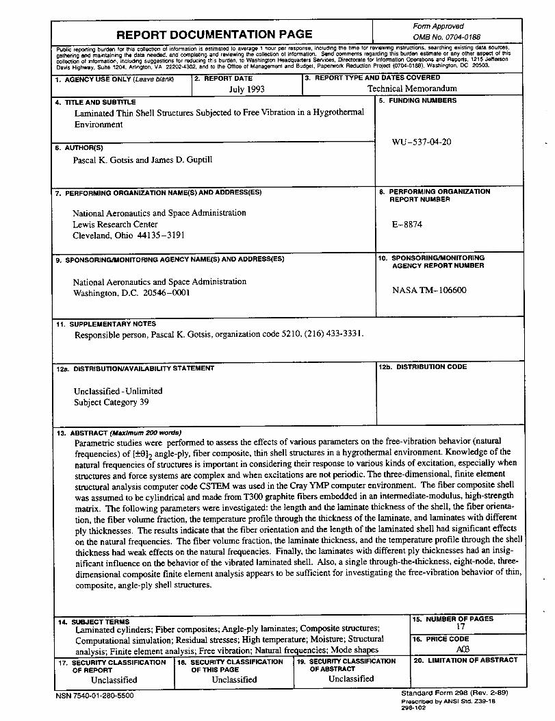
13. ABSTRACT (Maximum 200 words)
Parametric studies were performed to assess the effects of various parameters on the free-vibration behavior (natural
frequencies) of [_+0] 2 angle-ply, fiber composite, thin shell structures in a hygrothermal environment. Knowledge of the
natural frequencies of structures is important in considering their response to various kinds of excitation, especially when
structures and force systems are complex and when excitations are not periodic. The three-dimensional, finite element
structural analysis computer code CSTEM was used in the Cray YMP computer environment. The fiber composite shell
was assumed to be cylindrical and made from T300 graphite fibers embedded in an intermediate-modulus, high-strength
matrix. The following parameters were investigated: the length and the laminate thickness of the shell, the fiber orienta-
tion, the fiber volume fraction, the temperature profile through the thickness of the laminate, and laminates with different
ply thicknesses. The results indicate that the fiber orientation and the length of the laminated shell had significant effects
on the natural frequencies. The fiber volume fraction, the laminate thickness, and the temperature profile through the shell
thickness had weak effects on the natural frequencies. Finally, the laminates with different ply thicknesses had an insig-
nificant influence on the behavior of the vibrated laminated shell. Also, a single through-the-thickness, eight-node, three-
dimensional composite finite element analysis appears to be sufficient for investigating the free-vibration behavior of thin
composite, angle-ply shell structures.
14. SUBJECT TERMS
Laminated cylinders; Fiber composites; Angle-ply laminates; Composite structures;
Computational simulation; Residual stresses; High temperature; Moisture; Structural
analysis; Finite element analysis; Free vibration; Natural frequencies; Mode shapes
17. SECURITY CLASSIFICATION 18. SECURITY CLASSIFICATION 19. SECURITY CLASSIRCATION
OF REPORT OF THIS PAGE OF ABSTRACT
Unclassified Unclassified Unclassified
NSN 7540-01-280-5500
15. NUMBER OF PAGES
17
16. PRICE CODE
20. LIMITATION OF AB,_¥RACT
Standard Form 298 (Rev. 2-89)
Prescribed by ANSI Std. Z39-18298-102


![Supersonic Flutter of a Spherical Shell Partially …Ganapathi [12]et al. modeled an orthotropic and laminated aniso-tropic cylindrical shell in supersonic flow using FEM and analyzed](https://img.pdfslide.net/doc/110x75/5e3e4d56bb497d7d23496b67/supersonic-flutter-of-a-spherical-shell-partially-ganapathi-12et-al-modeled-an.jpg)