Embed Size (px)
Citation preview

LAND APPLICATION SYSTEMS

OUTLINE OF PRESENTATION
1. Types of Land Applications: Brief Overview.2. Definitions: Basic Terminology3. Subsurface, Shallow Systems: In Depth
a. Leachfieldsb. Mound Systemsc. Seepage Pits
4. Land Disposal Systems: In Depth Coveragea. Slow Rate (SR) Infiltration Systemsb. Rapid Infiltration (RI) Systemsc. Overland Flow Systemsd. Planning and designd. Comparison

DEFINITIONS
Effluent: Flow going out of or leaving a process.Influent: Flowing intoBOD: Biological oxidation demandTSS: Total suspended solidsTN: Total nitrogenTP: Total phosphorousFC: Fecal ColiformAWT: Advanced water treatment SAR: Soil absorption rateSR: Slow rateRI: Rapid infiltrationOF: Overland flow

Types of Land Application Systems: Three Basic Types
1. SUBSURFACE, SHALLOW AND DEEP SYSTEMS
Used in single dwellings and small clusters of dwellings
2. LAND DISPOSAL SYSTEMSUsed for pretreated municipal effluents
3. IRRIGATION AND LANDSCAPE USESUsed for final treatment and discharge of wastewater on vegetated plots

Types of Land Application Systems
• The greater the waste strength, the larger the system must be.
• This is true for all system types, and although each type of system introduces water into the soil differently, sizing for the system you choose is critical.
• At some point the soil will not accept any more wastewater, causing failure.

SUBSURFACE, SHALLOW SYSTEMS

SUBSURFACE, SHALLOW SYSTEMS
• Used for single dwelling or small clusters of dwellings
• In California there’s about 1 million households currently being served by these systems

SUBSURFACE, SHALLOW SYSTEMS
Three most common shallow subsurface systems:
1. Leachfields (a.k.a. Leaching Chambers)
2. Mound Systems
3. Seepage Pits

SUBSURFACE, SHALLOW SYSTEMS: LEACHFIELDS
SUBSURFACE, SHALLOW SYSTEMS: LEACHFIELDS
• Used to dispose of previously treated effluents (usually originally treated by means of septic tank)

SUBSURFACE, SHALLOW SYSTEMS: LEACHFIELDS
• Usually set of leaching chambers in trenches
• Connected to primary treatment system by a pipe
• Effluent is distributed into the soil

SUBSURFACE, SHALLOW SYSTEMS: LEACHFIELDS

ADVANTAGES:
• Easy and economic to construct
• Soil in trenches not likely to be compacted
• Extended useful life: low intrusion on soil and silt
• Small footprint
SUBSURFACE, SHALLOW SYSTEMS: LEACHFIELDS

DISADVANTAGES:
• Not well suited for soils with high percolation rates (e.g. sandy soils)
• Not well suited for soils with high groundwater levels
SUBSURFACE, SHALLOW SYSTEMS: LEACHFIELDS

SUBSURFACE, SHALLOW SYSTEMS: LEACHFIELDS
Item Minimum Distance, ft
Private Water Supply Well 100Public Water Supply Well 300Leak or Impoundment 50Stream or Open Ditch 25Property Lines 10Water Line Under Pressure 10Sewer Interceptor Drain 25Source: Schultheis, 1999
Setback distances from leaching chamer disposal areas
Setback distances:

SUBSURFACE, SHALLOW SYSTEMS: LEACHFIELDS
Long-Term Acceptance Rate (gpd/ft./yr)Soil Type Natural Soil SaproliteSands 0.8 – 1.0 0.4 – 0.6Coarse Loams 0.6 – 0.8 0.1 – 0.4Fine Loams 0.3 – 0.6 -Clays 0.1 – 0.4 -
LEACHING CHAMBER LONG-TERM ACCEPTANCE RATE
Soil Acceptance Rate:

SUBSURFACE, SHALLOW SYSTEMS: LEACHFIELDS
Estimated Cost of Leachfield*Description Cost ($)Construction costsingle family- if site is suitable 2000-5000single family- if site is inadequate >10000
Operation CostSeptic Cleaning 500-1500/cleaning*Factors effecting cost: soil type, price of land, site topography, groundwater level
Preliminary Cost Estimate:

SUBSURFACE, SHALLOW SYSTEMS: LEACHFIELDS
The seat under the old oak tree in a leachfield at Brookmans Park

SUBSURFACE, SHALLOW SYSTEMS: MOUND SYSTEM

• Used to further treat pre-treated effluents
• Comprised of pressure-dose sand filters that lie above the ground
• Discharge directly to the soil
SUBSURFACE, SHALLOW SYSTEMS: MOUND SYSTEM

SUBSURFACE, SHALLOW SYSTEMS: MOUND SYSTEM

Suited for sites with restriction such as:
• Slow or fast permeability
• Shallow soil cover over creviced or porous bedrock
• Elevated water table
SUBSURFACE, SHALLOW SYSTEMS: MOUND SYSTEM

SUBSURFACE, SHALLOW SYSTEMS: MOUND SYSTEM

SUBSURFACE, SHALLOW SYSTEMS: MOUND SYSTEM

ADVANTAGES:• Accommodate sites that otherwise
are not suitable for in-ground or at-gate onsite disposal
• Do not discharge directly to surface water bodies
• Can be used in most climates• Little excavation required
SUBSURFACE, SHALLOW SYSTEMS: MOUND SYSTEM
Mound System
Advantages to the Mound Systems

DISADVANTAGES:• Relatively high construction costs• Mound location can affect surface drainage pattern• Require pumping/siphon systems• Aesthetically obtrusive• Seepages/Leakages can affect mount integrity
SUBSURFACE, SHALLOW SYSTEMS: MOUND SYSTEM

SUBSURFACE, SHALLOW SYSTEMS: MOUND SYSTEM
Parameter Value
Depth of high water table (permanent or seasonal) 10 in.Depth to crevice bedrock 2 ft.Depth to non-crevice bedrock 1 ft.Permeability of top 10 in. Moderately lowSite slope 25%Filled site Yesa
Over old system Yesb
Flood plains Noa Suitable according to soil criteria (texture, structure, consistence).b The area and backfill must be treated as fill because it is a disturbed site.Source: Converse and Tyler, 1990.
Recommended soil and site criteria for "Wisconsin" Mound System
Criteria for Design:

SUBSURFACE, SHALLOW SYSTEMS: MOUND SYSTEM
Item Cost
Construction CostsSeptic tank (1000 gallon concrete tank)
1,000
Dosing chamber (includes pump and controls)
2,000
Mound structure 6,000Total Construction Costs 9000
Non-Component CostsSite evaluation 500Permits 250Total Costs 9,750Annual O&M CostsLabor @$20/hr. 20 per yearPower @8 cents/kWh 35 per yearSeptic tank pumping 75 to 150
every 3 years
Capital Costs
Source: Ayres Associates, Inc., 1997
Typical Cost Estimate for a Single Home Mound System
Cost Estimate for Mound Systems:

SUBSURFACE, SHALLOW SYSTEMS: MOUND SYSTEM
Picture of a typical on-site mound system

SUBSURFACE, SHALLOW SYSTEMS: SEEPAGE PITS

• Used for disposal of treated wastewater effluents
• Brick, block, or precast chambers placed in deep excavations surrounded by gravel of crushed rocks
• Effluents enter the chamber where it’s contained until it seeps through the walls and goes into the excavation wall
SUBSURFACE, SHALLOW SYSTEMS: SEEPAGE PITS

SUBSURFACE, SHALLOW SYSTEMS: SEEPAGE PITS
SUBSURFACE, SHALLOW SYSTEMS: SEEPAGE PITS
ADVANTAGES:
•Easy to construct
•Requires little maintenance
•Able to treat on sites with inadequate land resources for a standard absorption field
SUBSURFACE, SHALLOW SYSTEMS: SEEPAGE PITS
DISADVANTAGES:
•Danger of groundwater contamination
•Effluent is concentrated at one point, rather than large area
•Small flow able to be treated

SUBSURFACE, SHALLOW SYSTEMS: SEEPAGE PITS

LAND DISPOSAL SYSTEMS

• Used to dispose of pretreated municipal effluents
• Not widely used due to large land requirements, exacerbated by code-required setbacks (often including buffer areas and fencing)
• Also used less frequently due to requirement of significant pretreatment before application
LAND DISPOSAL SYSTEMS

Three main land disposal systems used for pretreated municipal effluents:
1. Slow-Rate Systems (SR)
2. Rapid Infiltration Systems (RI)
3. Overland Flow (OF)
LAND DISPOSAL SYSTEMS
LAND DISPOSAL SYSTEMS: SLOW-RATE SYSTEMS

• The oldest and most widely used form of land treatment, requires largest land area compared to the other land disposal systems
• Used to further treat wastewater effluent via contact with the soil-vegetation system
• Used when stringent requirements are placed on nutrients, pathogens, metals, and organics
• Used in agricultural, turf (e.g., golf courses, parks), and forest systems
LAND DISPOSAL SYSTEMS: SLOW-RATE SYSTEMS

• SR type 1- chosen to maximize amount of water to the minimum area of land
• SR type 2- chosen to optimize hydraulic loading for irrigation purposes
LAND DISPOSAL SYSTEMS: SLOW-RATE SYSTEMS

• Intended for wastewater treatment and hydraulic loading
• Limited by the hydraulic capacity of soil (nitrogen removal ability, etc.)
• Vegetation covers usually include perennial grasses due to the high nitrogen uptake ability, long WW application season, and low maintenance
LAND DISPOSAL SYSTEMS: SLOW-RATE SYSTEMS: Type 1

• Primarily intended for providing water and nutrients to agricultural, turf, and forest system
• Can not be applied to products consumed by humans
LAND DISPOSAL SYSTEMS: SLOW-RATE SYSTEMS: Type 2

LAND DISPOSAL SYSTEMS: SLOW-RATE SYSTEMS: Type 2
Treatment Plant and Golf Coarse:

LAND DISPOSAL SYSTEMS: SLOW-RATE SYSTEMS:
Slow Rate Spray Irrigation:

LAND DISPOSAL SYSTEMS: SLOW-RATE SYSTEMS:
Harvesting Forage:

LAND DISPOSAL SYSTEMS: SLOW-RATE SYSTEMS:
Spray Irrigation in Forest:

LAND DISPOSAL SYSTEMS: SLOW-RATE SYSTEMS:
Drip Irrigation:

LAND DISPOSAL SYSTEMS: SLOW-RATE SYSTEMS:
b.) Recovery Pathways
Underdrains Wells
a.) Application Pathway
Applied Wastewater
Evapotranspiration
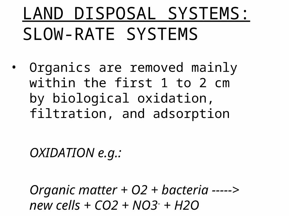
• Organics are removed mainly within the first 1 to 2 cm by biological oxidation, filtration, and adsorption
OXIDATION e.g.:
Organic matter + O2 + bacteria -----> new cells + CO2 + NO3- + H2O
LAND DISPOSAL SYSTEMS: SLOW-RATE SYSTEMS

LAND DISPOSAL SYSTEMS: SLOW-RATE SYSTEMS
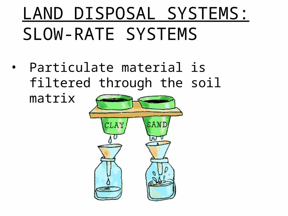
• Particulate material is filtered through the soil matrix
LAND DISPOSAL SYSTEMS: SLOW-RATE SYSTEMS

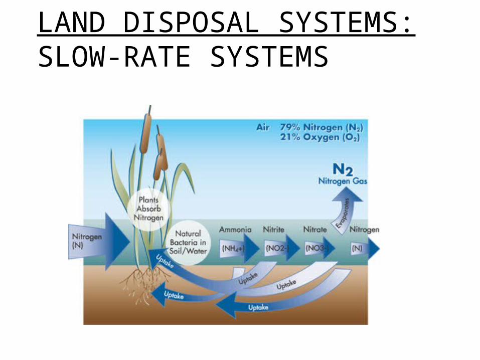
Nitrogen is removed by:
• Vegetation uptake
• Biological denitrification
• Ammonia volatilization
• Retention within soil matrix
LAND DISPOSAL SYSTEMS: SLOW-RATE SYSTEMS
LAND DISPOSAL SYSTEMS: SLOW-RATE SYSTEMS

LAND DISPOSAL SYSTEMS: SLOW-RATE SYSTEMS
• Phosphorus removal via crop uptake and fixation processes in the soil matrix.

LAND DISPOSAL SYSTEMS: SLOW-RATE SYSTEMS
• SR Systems are very effective at removing harmful wastewater constituents
PARAMETER PERCENT REMOVALBOD 90 to 99+ percentTSS 90 to 99+ percentTN 50 to 90 percentTP 80 to 99+ percentFECAL COLIFORM 99.99+ percent
LAND DISPOSAL SYSTEMS: SLOW-RATE SYSTEMSADVANTAGES:
• Significantly reduced operational, labor, chemical, and energy requirements compared to conventional wastewater treatment systems.
• Economic return from the use and re-use of water and nutrients to provide marketable crops.
• Little or no disposal of effluent production.
• Recycling and reuse of water reduces water distribution and treatment costs for crop irrigation.
LAND DISPOSAL SYSTEMS: SLOW-RATE SYSTEMSDISADVANTAGES:
•Large land requirements
Specific problems associated with poor site selection include:
• Soil structure dispersion resulting from high dissolved salts concentration.
• Runoff and erosion for sites with steep slopes or lack of adequate erosion protection.
• Inadequate soil or groundwater characterization resulting in operational hydraulic problems.

LAND DISPOSAL SYSTEMS: SLOW-RATE SYSTEMS
Item RangeField Area 56 to 560 acres/MGD
Application Rate2 to 20 ft/yr
(0.5 to 4 in/wk)BOD Loading 0.2 to 5 lb/acre/d
Soil Depth at least 2 to 5 ftSoil Permeability 0.06 to 2.0 in/hr
Lower Temperature Limit 25 deg FApplication Method sprinkler or surface
Pretreatment Required preliminary & secondaryParticle Size
(for sprinkler applications)Solids less than 1/3
sprinkler nozzle
SR Design Criteria
Source: Crites, et al., 2000.
General design parameters for SR system:
LAND DISPOSAL SYSTEMS: SLOW-RATE SYSTEMS
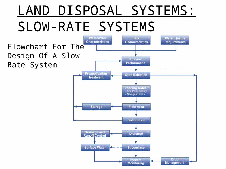
Flowchart For The Design Of A Slow Rate System

LAND DISPOSAL SYSTEMS: SLOW-RATE SYSTEMS
A preliminary estimate of costs for planning purposes:
SR Estimated Costs*Construction Costs ($) O&M Costs ($/yr)
C = 3.187(Q)0.9331 C = 0.1120(Q)0.8176
C = 1.71(Q)0.999 C = 0.205(Q)0.5228
*Costs valid up to ~10 MGD.
Slow Rate, Sprinklers, Underdrain
Slow Rate, Sprinklers, Not Underdrained
C = costs in millions of dollarsQ = design flow, MGD

LAND DISPOSAL SYSTEMS: RAPID INFILTRATION

Usually used for:
• Ground water recharge
• Surface water recharge
• Recovery of renovated water (by wells or underdrains) for reuse
• Temporary storage of treated waters
NEED TO COVER THESE WORDS!
more
LAND DISPOSAL SYSTEMS: RAPID INFILTRATION

LAND DISPOSAL SYSTEMS: RAPID INFILTRATION
• Wastewater percolates through the soil and is treated through downward flow
• Vegetation is NOT a part of the treatment

LAND DISPOSAL SYSTEMS: RAPID INFILTRATION
Hydraulic pathways for RI systems:
a.) Hydraulic Pathway
Percolation
Evaporation
Applied Wastewater
Flooding Basins Recovered Water
b.) Recovery Pathways
Underdrains
c.) Natural Drainage Into Surface Waters
Flooding Basin

LAND DISPOSAL SYSTEMS: RAPID INFILTRATION
RI DESIGN CRITERIAItem
Basin Infiltration Area
Hydraulic Loading Rate
BOD Loading Soil Depth
Soil Permeability Wastewater Application Period Drying PeriodSoil Texture
Height of DikesApplication Method Pretreatment RequiredSource: Crites, et al., 2000.
Range
0.15 m (0.5 ft) above maximum expected water levelflooding or sprinklingprimary or secondary
0.4-4 ha (1-10 acres)Individual Basin Size (at least 2 basins in parallel)
0.3-5.5 ha/103m3/d (3-56 acres/MGD)
6-90 m/yr (20-300 ft/yr) [6-92 m3/m2/yr (150-2250 gal/ft2/yr)]
22-112 kg/ha/d (20 to 100 lb/acre/d)at least 3-4.5 m (10-15 ft)
at least 1.5 cm/hr (0.6 in/hr)4 hrs to 2 wks8 hrs to 4 wkscoarse sands, sandy, gravels
•Most RI failures are due to improper soil elevations.
• Soil depth, soil permeability, and depth to groundwater are the most important factors in site evaluation.

LAND DISPOSAL SYSTEMS: RAPID INFILTRATION
Removal rates are dependent on:
• Wastewater characteristics
• Soil characteristics
• Travel distance
• Climatic and seasonal variables

LAND DISPOSAL SYSTEMS: RAPID INFILTRATION
• BOD, Suspended Solids, and Fecal Coliforms are almost completely removed
• Nitrogen removal is about 50-99%
• Phosphorus removal is about 70-99%

LAND DISPOSAL SYSTEMS: RAPID INFILTRATION
Advantages:•Gravity distribution methods consume no energy.
• No chemicals are required.
• RI is a simple and economical treatment.
•The process is not constrained by seasonal changes.
• Effluent is of excellent quality.

LAND DISPOSAL SYSTEMS: RAPID INFILTRATION
Advantages:• The process is very reliable with sufficient resting periods.
• The process is suitable for small plants where operator expertise is limited.
• RI provides a means for groundwater recharge, controlling And then there
were threegroundwater levels, recovering renovated water for reuse or discharge to a particular surface water body, and temporary storage of renovated water in the aquifer.
LAND DISPOSAL SYSTEMS: RAPID INFILTRATION
Disadvantages:• Usually won’t meet nitrogen levels required
for drinking water aquifer discharge.
• Requires long term commitment of significant land area
• Requires annual removal of accumulated deposits of organic matter
• May require occasional removal and disposal of the top few inches of soil
• Clogging can occur when influent is received at high application rates from algal laden lagoons and ponds

LAND DISPOSAL SYSTEMS: RAPID INFILTRATION
• Flowchart For The Design Of A Rapid Infiltration System:

LAND DISPOSAL SYSTEMS: RAPID INFILTRATION
Estimating Costs for Rapid Infiltration Systems
(O&M includes the annual tillage of infiltration surfaces, and the repair of dikes, fences, and roads every 10 years.)
Cost Estimation Equations*
Construction ($)
C = 0.580(Q)0.888 C=0.054(Q)0.756
C = 0.597(Q)0.857 C=0.058(Q)0.756
C=0.683(Q)0.886 C=0.075(Q)0.641
Source: Crites, et al., 2000
C=Cost in millions of dollars; Q=wastewater flow in MGD
*Cost of preliminary treatment, monitoring wells, and transmission from preliminary treatment facilty not included.
Equations valid for up to 3785 m3/d (10 MGD) wastewater flow
Case I: RI w. no underdrains, no recovery wells
Case II: RI w. 50 ft deep recovery wells
Case III: RI w. underdrains
Operation and Maintenance ($)
LAND DISPOSAL SYSTEMS: OVERLAND FLOW SYSTEMS

LAND DISPOSAL SYSTEMS: OVERLAND FLOW SYSTEMS
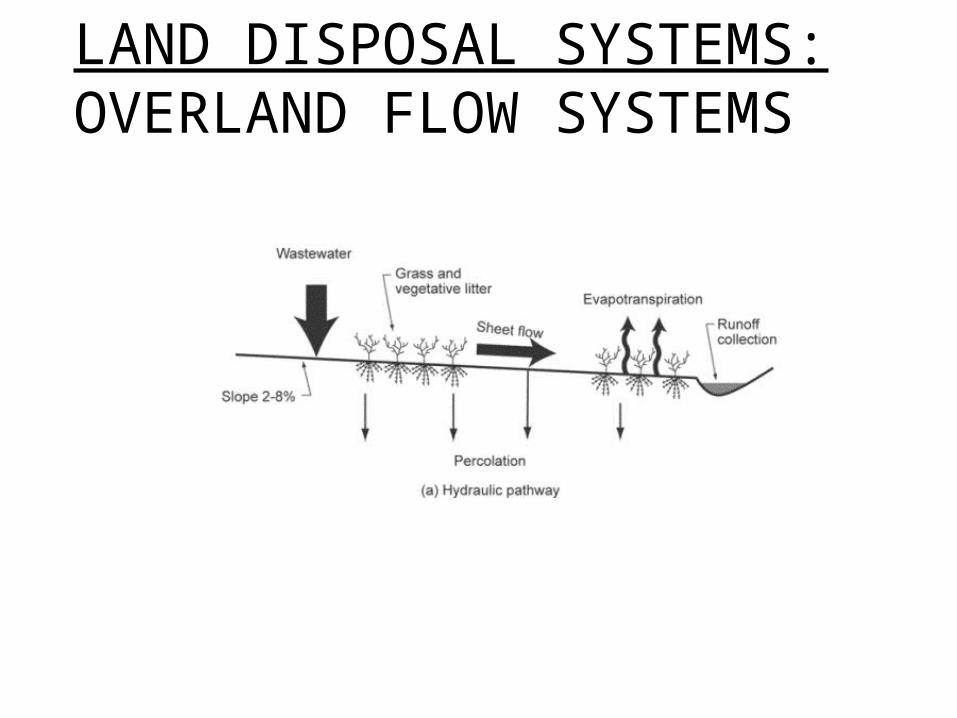
• Used to achieve secondary treatment effluent quality when applying effluents comming from primary treatment facilities.
• High removal of Nitrogen, BOD, and Suspended Solids

LAND DISPOSAL SYSTEMS: OVERLAND FLOW SYSTEMS
• Applying of previously treated wastewater effluents to a vegetation-covered, graded land
• Applied via grated pipes or nozzles at top of slope or by sprinkler systems within the site
LAND DISPOSAL SYSTEMS: OVERLAND FLOW SYSTEMS

LAND DISPOSAL SYSTEMS: OVERLAND FLOW SYSTEMS
•Best suited for sites with relatively impermeable soils

LAND DISPOSAL SYSTEMS: OVERLAND FLOW SYSTEMS
Land Requirements:
• Low permeability soils
• Grading within 2-8%

LAND DISPOSAL SYSTEMS: OVERLAND FLOW SYSTEMS
Perennial grasses used for:
• Erosion control
• Slope stability
• Effluent treatment

LAND DISPOSAL SYSTEMS: OVERLAND FLOW SYSTEMS
Removal mechanisms for BOD and Suspended Solids:
• Biological Oxidation
• Sedimentation
• Filtration

LAND DISPOSAL SYSTEMS: OVERLAND FLOW SYSTEMS
Removal mechanisms for Nitrogen (typically removes 75-90%):
• Plant uptake
• Denitrification
• Ammonia Volatilization

LAND DISPOSAL SYSTEMS: OVERLAND FLOW SYSTEMS
Removal mechanisms for Phosphorus (typically removes 50-70%- can increase by addition of alum of ferric chloride prior to land application):
• Fixation processes in the soil matrix
• Crop uptake

LAND DISPOSAL SYSTEMS: OVERLAND FLOW SYSTEMS
• Effluent is collected in ditches and can be reused or discharged to a surface water body
• If discharged to surface body: NPDES permit required

LAND DISPOSAL SYSTEMS: OVERLAND FLOW SYSTEMS
• Flowchart For the Design Of Overland Flow Systems
LAND DISPOSAL SYSTEMS: COMPARISON
LAND DISPOSAL SYSTEMS: COMPARISON
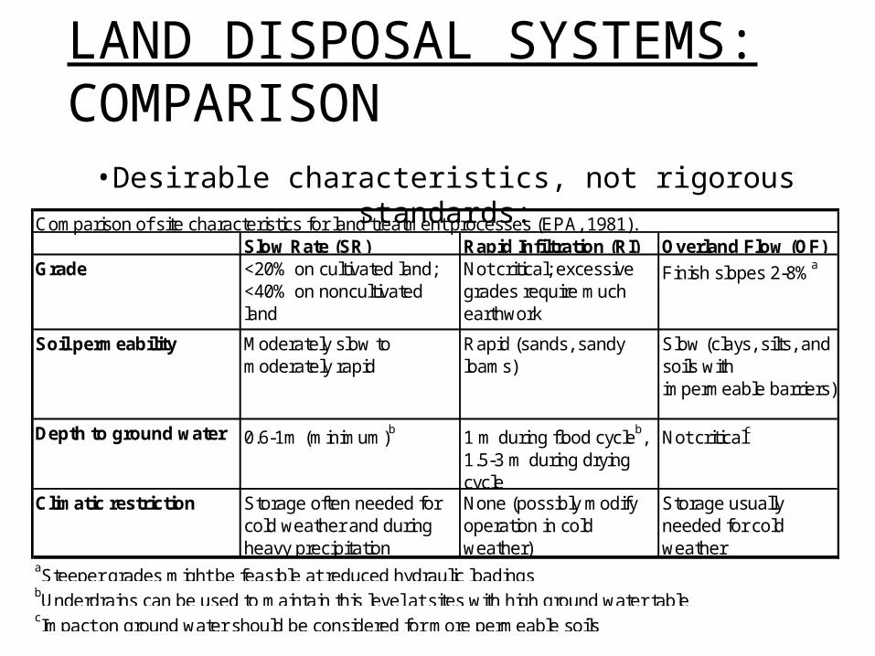
Comparison of site characteristics for land treatment processes (EPA, 1981).Slow Rate (SR) Rapid Infiltration (RI) Overland Flow (OF)
Grade <20% on cultivated land; <40% on noncultivated land
Not critical; excessive grades require much earthwork
Finish slopes 2-8%a
Soil permeability Moderately slow to moderately rapid
Rapid (sands, sandy loams)
Slow (clays, silts, and soils with impermeable barriers)
Depth to ground water 0.6-1m (minimum)b 1 m during flood cycleb, 1.5-3 m during drying cycle
Not criticalc
Climatic restriction Storage often needed for cold weather and during heavy precipitation
None (possibly modify operation in cold weather)
Storage usually needed for cold weather
aSteeper grades might be feasible at reduced hydraulic loadingsbUnderdrains can be used to maintain this level at sites with high ground water tablecImpact on ground water should be considered for more permeable soils
•Desirable characteristics, not rigorous standards:

LAND DISPOSAL SYSTEMS: COMPARISON
•Terrestrial treatment units, design features, and performance (Reed et al, 1995):
Disposal System
Treatment Goals
Climate Needs Vegitation
Area* (ha)
Hydraulic Loading (m/y)
Effluent Characteristics (mg/L)
SRSecondary, or AWT
Warmer Seasons YES 23-280 0.5-6
BOD < 2 TSS < 2
TN < 31
TP < 0.1 FC = 0
RI
Secondary, or AWT, or Groundwater Recharge NONE NO 3-23 6-125
BOD < 5 TSS < 2
TN < 101
TP < 1 FC = 10
OFSecondary, N removal
Warmer Seasons YES 6-40 3-20
BOD < 10 TSS < 10
TN < 101
* For design flow of 3785 m3/d1Nitrogen (N) removal depends on type of crop and management
AWT = advanced water treatment, SR = slow rate, RI = rapid infiltration, OF = overland flow, BOD = biological oxygen demand, TSS = total suspended solids, TN = total N, TP = total phosphorus (P), FC = fecal coliforms, counts/100mL

LAND DISPOSAL SYSTEMS: COMPARISON
Constituent Average Upper Range Average Upper Range Average Upper Range
BOD (mg/L) <2 <5 5 <10 10 <15SS (mg/L) <1 <5 2 <5 10 <20Ammonia as N (mg/L) <0.5 <2 0.5 <2 <4 <8TN (mg/L) 3e <8e 10 <20 5f <10f
TP (mg/L) <0.1 <0.3 1 <5 4 <6FC (#/100mL) ?? <10 10 <200 200 <2000
eConcentration depends on loading rate and cropfHigher values expected when operating through a moderately cold winter or when using secondary effluents at high rates.
aQuality expected with loading rates at the mid to low end of the application rangebPercolation of primary or secondary effluent through 1.5 m (5ft) of unsaturated soilcPercolation of primary or secondary effluent through 5.5 m (15ft) of unsaturated soil; P and FC removals increaseddTreating comminuted, screened wastewater using a slope length of 30-36m (100-120 ft).
Slow Rateb Rapid Infiltrationc Overland Flowd
Expected quality of treated water from land treatment processesa (EPA, 1991)
•Expected water quality: function of hydraulic loading, available soils for treatments, vegetation.

LAND APPLICATION SYSTEMS

LAND APPLICATION SYSTEMS