Embed Size (px)
Citation preview

Land-FormPANORAMATM
User Guide

Preface
Land-Form PANORAMA User Guidev2.0 - 06/1997 © Crown copyright
Preface
Thank you for choosing Land-Form PANORAMA™ for yourbusiness needs.
This User Guide describes the data formats and specification forLand-Form PANORAMA. It is intended to be used by systemsuppliers and application programmers as a guide to loadingand manipulating the data.
Land-Form PANORAMA™ is supplied in two data formats:● BS 7567 (NTF v2.0)● Drawing Interchange File (DXF).
If the two format versions differ in their treatment of a particularaspect, the specific differences will be stated. Icons, as shownbelow, will be used to denote these differences.
For convenience BS 7567 (NTF v2.0 Level 2) isreferred to as NTF and BS 7567 (NTF v2.0 level 5) isreferred to as NTF level 5 in this Reference Section.
Drawing Interchange File (DXF) is referred to as DXFin this Section.DXF
BS 7567
NTF
Land-Form PANORAMA User Guidev2.0 - 06/1997 © Crown copyright
Preface
Contact DetailsCustomer Services - Digital Help Desk will be pleased to deal with yourenquiries.Customer Services - Digital Help DeskTelephone: 01703 792773Fax: 01703 792324E-mail: [email protected]
or write to:
Customer Services - Digital Help DeskOrdnance SurveyRomsey RoadSOUTHAMPTONUnited KingdomSO16 4GU
Product PerformanceIf you have any problems or identify any errors in the data, please completethe Product Performance Report Form at Appendix F.
LiabilityThis User Guide has been checked and validated before issue and everyendeavour made to ensure that the contents are accurate. If you find anyerrors or omissions please write to us at the address shown above so that wecan investigate them.
Ordnance Survey makes every effort to ensure that data supplied are freefrom errors and omissions. We will remedy, as soon as reasonablypracticable, errors and omissions the Customer notifies to Ordnance Survey inwriting. It is the Customer's responsibility to ensure that data ordered aresuitable for the intended purpose. Ordnance Survey will not be liable to theCustomer or any other party for any loss, damage, inconvenience or expenseresulting from the use of, or reliance upon, the data.
Trade MarksOrdnance Survey and Landranger are registered trade marks and the OSsymbol and Land-Form PANORAMA are trade marks of Ordnance Survey, theNational Mapping Agency of Great Britain.
MS-DOS is a registered trade mark of Microsoft Corporation; UNIX is aregistered trade mark of UNIX Systems Laboratories. AutoCAD is a registeredtrade mark and DXF is a trade mark of Autodesk Inc.
Preface
Land-Form PANORAMA User Guidev2.0 - 06/1997 © Crown copyright
Ordnance Survey Development/Demonstration Licence
Ordnance Survey wishes to encourage the development anduse of digital map data in commercial products. It recognisesthat businesses involved in this area will need to use andreproduce Ordnance Survey material during the course ofproduct development and to demonstrate their ideas in order toattract interest in potential products. In order to carry out theseactivities users should apply for an Ordnance SurveyDevelopment/Demonstration Licence.
For further information on any of these matters contact:
CopyrightOrdnance SurveyRomsey RoadSOUTHAMPTONSO16 4GU
Telephone: 01703 792684
Fax: 01703 792535

Land-Form PANORAMA User Guidev2.0 - 06/1997 © Crown copyright
Preface
Table of Contents
Land-Form PANORAMA User Guidev2.0 - 06/1997 © Crown copyright
Contents - Page 1
Table of Contents
Chapter 1 Overview of Land-Form PANORAMA 1.1
Digital Contours 1.1
Digital Terrain Model Data (DTM) 1.1
Applications 1.2
Supply Formats and Media 1.2Supply Formats 1.2Land-Form PANORAMA Supply Media 1.3
Chapter 2 An Overview of NTF v2.0 2.1
Conventions Used in This Guide 2.1
General 2.2Record Size 2.2Continuation Mark {CONT_MARK} 2.2Record Terminator {EOR} 2.2Transfer Set 2.2
Transfer Set Structure 2.3Volume Records 2.3Database Records 2.3Section Records 2.4
Supply of Data on Unformatted Media 2.5
Supply of Data on Formatted Media 2.6
File Naming Conventions Used 2.9
Chapter 3 Land-Form PANORAMA Data in NTF 3.1
Land-Form PANORAMA Contour Data 3.1Section Data Records 3.1
Point Feature 3.1Line Feature 3.1Coordinates 3.2Feature Codes 3.2
Land-Form PANORAMA Digital Terrain Models 3.3Introductory Records for DTMs in NTF v2.0 Level Five 3.3Section Data Records 3.3Coordinate System 3.4
Table of Contents
Land-Form PANORAMA User Guidev2.0 - 06/1997 © Crown copyright
Contents - Page 2
Chapter 4 An Overview of DXF 4.1
Introduction 4.1General 4.1
Overview 4.1Structure of Land-Form PANORAMA Contours 4.1Line Features 4.2Structure of Land-Form PANORAMA DTMs 4.2
DXF Layers 4.3Generalised Feature Record Representation 4.3Layer Names 4.3
Layers Lists 4.4Layer Names and Descriptions for Land-Form 4.4 PANORAMA Contours in DXFLayer Names and Descriptions for Land-Form 4.5 PANORAMA DTMs in DXFMap Footnotes 4.6
DXF File Structure for Land-Form PANORAMA 4.8
Appendix A The National Grid A.1
Appendix B Record Definitions for the Transfer of B.1 Land-Form PANORAMA Contour Data in NTF
NTF Record List B.1
Volume Header Record [VOLHDREC] 01 B.2
Database Header Record [DBHREC] 02 B.3
Feature Classification Record [FEATCLASS] 05 B.4
Section Header Record [SECHREC] 07 B.5
Point Record [POINTREC] 15 B.6
Two-Dimensional Geometry Record [GEOMETRY1] 21 B.6
Line Record [LINEREC] 23 B.7
Attribute Description Record [ATTDESC] 40 B.7
Volume Terminator Record [VOLTERM] 99 B.8
Table of Contents
Land-Form PANORAMA User Guidev2.0 - 06/1997 © Crown copyright
Contents - Page 3
Appendix C Record Definitions for the Transfer of C.1 Land-Form PANORAMA DTM Data in NTF
NTF Record List C.1
Volume Header Record [VOLHDREC] 01 C.2
Database Header Record [DBHREC] 02 C.3
Data Description Record [DATADESC] 03 C.4
Data Format Record [DATAFMT] 04 C.5
Section Header Record [SECHREC] 07 C.6
Grid Header Record [GRIDHREC] 50 C.8
Grid Data Record [GRIDREC] 51 C.9
Volume Termination Record [VOLTERM] 99 C.10
Appendix D Record Definitions for the Transfer of D.1 Land-Form PANORAMA Data in DXF
Header Section D.1Tables Section D.4Linetype Table D.5Layer Table D.6Style Table D.7Blocks Section D.10Entities Section D.11End of File Group D.15
Appendix E Terms and Conditions E.1
Use of Land-Form PANORAMA E.1
Delivery of Land-Form PANORAMA E.1
Invoice E.1
Copyright E.2
Appendix F Product Performance Report Form F.1

Table of Contents
Land-Form PANORAMA User Guidev2.0 - 06/1997 © Crown copyright
Contents - Page 4

Land-Form PANORAMA User Guidev2.0 - 06/1997 © Crown copyright
Page 1.1
Chapter 1 Overview of Land-Form PANORAMA
Chapter 1 Overview of Land-Form PANORAMA
Land-Form PANORAMA is available as either digital Contoursor Digital Terrain Models (DTMs).
Digital Contours
Land-Form PANORAMA Digital Contours are a digitalrepresentation of the graphic contours used to produce theOrdnance Survey Landranger maps. Additional spot heights,ridge and form lines were added to facilitate the creation of theDigital Terrain Models, these additional features are included inthe contour product.
Contours are in vector format and are at 10 metre elevationintervals.
Spot heights are to the nearest metre.
The data has been captured in 20 km by 20 km tiles and isavailable for the whole country (see Appendix A).
The accuracy of Digital Contours is typically better than 3 m(Root Mean Square Error).
Digital Terrain Model Data (DTM)
DTM consists of height values at each intersection of a 50 metrehorizontal grid, the values have been mathematicallyinterpolated from the contours on the Landranger maps.
Variations in DTM accuracy are to be expected depending uponthe nature of the ground. DTM height accuracy is no greaterthan one half of the vertical interval of the source contour data.
The data has been captured in 20 km x 20 km tiles, and isavailable for the whole country (see Appendix A).
Chapter 1 Overview of Land-Form PANORAMA
Land-Form PANORAMA User Guidev2.0 - 06/1997 © Crown copyright
Page 1.2
Applications
This product offers many exciting opportunities for modelling thereal world more closely by the use of three dimensionalcomputing techniques.
The data supports such applications as:
● terrain analysis
● drainage analysis
● visual impact studies
● radio wave propagation.
Supply Formats and Media
Supply Formats
Land-Form PANORAMA contours are available in :
● NTF level 2 See Chapter 3
● DXF See Chapter 4.
Land-Form PANORAMA DTMs are available in:
● NTF Level 5 See Chapter 3
● DXF See Chapter 4.
Land-Form PANORAMA User Guidev2.0 - 06/1997 © Crown copyright
Page 1.3
Chapter 1 Overview of Land-Form PANORAMA
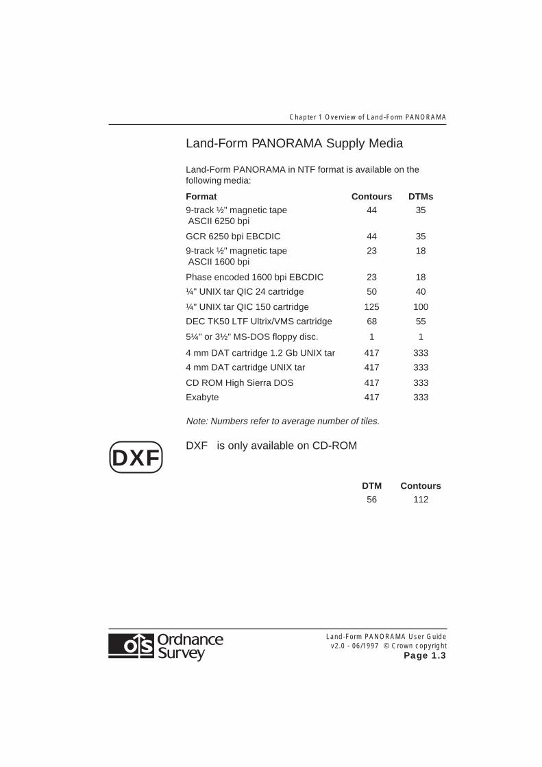
Land-Form PANORAMA Supply Media
Land-Form PANORAMA in NTF format is available on thefollowing media:
Format Contours DTMs
9-track ½" magnetic tape 44 35 ASCII 6250 bpi
GCR 6250 bpi EBCDIC 44 35
9-track ½" magnetic tape 23 18 ASCII 1600 bpi
Phase encoded 1600 bpi EBCDIC 23 18
¼" UNIX tar QIC 24 cartridge 50 40
¼" UNIX tar QIC 150 cartridge 125 100
DEC TK50 LTF Ultrix/VMS cartridge 68 55
5¼" or 3½" MS-DOS floppy disc. 1 1
4 mm DAT cartridge 1.2 Gb UNIX tar 417 333
4 mm DAT cartridge UNIX tar 417 333
CD ROM High Sierra DOS 417 333
Exabyte 417 333
Note: Numbers refer to average number of tiles.
DXF is only available on CD-ROM
DTM Contours
56 112
DXF

Chapter 1 Overview of Land-Form PANORAMA
Land-Form PANORAMA User Guidev2.0 - 06/1997 © Crown copyright
Page 1.4
Land-Form PANORAMA User Guidev2.0 - 06/1997 © Crown copyright
Page 2.1
Chapter 2 An Overview of NTF v2.0
Chapter 2 An Overview of NTF v2.0
Conventions Used in This Guide
Certain conventions are adopted as an aid to interpretation(although in the Appendices the convention is dropped wherethe context is self-evident).
[ ] Square brackets are placed around record names, eg[VOLHDREC].
{ } Curly brackets denote field names eg {REC_DESC} is theRecord Descriptor Field.
[ ]21 A two-digit number following square brackets denotes theRecord Descriptor which uniquely identifies the recordname between the brackets.
<S> This is the space character (ASCII code 32).
<3S> This denotes three successive space characters.
% The percentage character (ASCII code 37).
Chapter 2 An Overview of NTF v2.0
Land-Form PANORAMA User Guidev2.0 - 06/1997 © Crown copyright
Page 2.2
General
Record Size
NTF data is written to the output device in variable lengthrecords, with a maximum record length of 80 characters, whichincludes {CONT_MARK} and {EOR}.
Continuation Mark {CONT_MARK}
Continuation Records are used where the maximum physicalrecord length of 80 characters does not permit a logical recordto be transferred wholly within one physical record. Thepresence of a Continuation Record is indicated by the value ofthe Continuation Mark {CONT_MARK}, which immediatelyprecedes the Record Terminator {EOR}. The value of{CONT_MARK} is ‘1’ if there is a Continuation Record presentand ‘0’ if there is not.
Record Terminator {EOR}
The end of record terminator is the percent (%) (ASCII 37)character for both formatted and unformatted media.
Transfer Set
A transfer set normally equates to a single file except wherecontinuation volumes are used when the transfer set exceedsthe capacity of the media.
The data the customer receives is in one or more Transfer Sets.
Land-Form PANORAMA User Guidev2.0 - 06/1997 © Crown copyright
Page 2.3
Chapter 2 An Overview of NTF v2.0
Transfer Set Structure
Volume Records
Each Transfer Set starts with a compulsory Volume HeaderRecord [VOLHDREC] and terminates with a compulsory VolumeTerminator Record [VOLTERM].
As a transfer set may span one or more volumes, a field withinthe Volume Header Record indicates which volume in thesequence of volumes within the Transfer Set it is. Similarly, theVolume Termination Record ends either a single volume or acomplete transfer set. A field similar to the Continuation Mark isused to indicate completion or continuation.
Database Records
Database Records transfer information common to all data andtheir presentation in the subsequent section(s).
An NTF Transfer Set comprises one database. The databasecommences with a Database Header Record [DBHREC] whichsets up the database. It is followed by a number of otherdatabase records as indicated below.
Database Header Record [DBHREC]
This mandatory record indicates the commencement of adatabase and gives details of:
● The Database name
● NTF Release date
● Feature Classification Table Name
● Release data which applies to the whole transfer set.
Attribute Description Record [ATTDESC]
These records list and give descriptions of the attributes thatcan be applied to features within the Transfer Set. Theserecords are not present in Land-Form PANORAMA DTMs.

Chapter 2 An Overview of NTF v2.0
Land-Form PANORAMA User Guidev2.0 - 06/1997 © Crown copyright
Page 2.4
Feature Classification Record [FEATCLASS]
These records list and give descriptions of all possible featurecodes for the Transfer Set. These records are not present inLand-Form PANORAMA DTMs.
Data Description Record [DATADESC]
These records list and define new data fields used within newrecords defined in Data Format Records [DATAFMT]. Theserecords are not present in Land-Form PANORAMA Contours.
Data Format Record [DATAFMT]
These records list and define new records used to transfer datain the Digital Terrain Model. These records are not present inLand-Form PANORAMA Contours.
Section Records
The Section Records contain the data within the map tile. Thesection starts with the Section Header Record [SECHREC]followed by the Section Data Records.
Section Header Record [SECHREC]
This mandatory record starts a Section. It contains informationand parameters essential for understanding, interpreting andprocessing some of the fields within the data. It establishes theunit of measure for X, Y and Z coordinates, origins and otherconstants.
Section Data Records
These contain all the features within the section. The recordsused within Land-Form PANORAMA Contours and DTMs differ.
Land-Form PANORAMA User Guidev2.0 - 06/1997 © Crown copyright
Page 2.5
Chapter 2 An Overview of NTF v2.0
Supply of Data on Unformatted Media
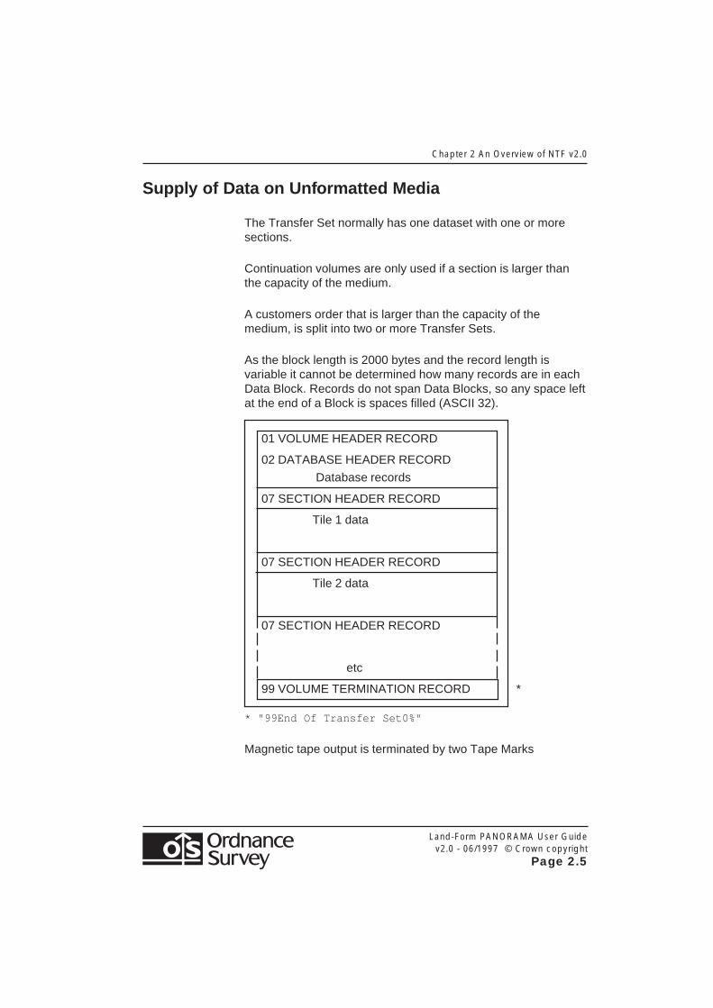
The Transfer Set normally has one dataset with one or moresections.
Continuation volumes are only used if a section is larger thanthe capacity of the medium.
A customers order that is larger than the capacity of themedium, is split into two or more Transfer Sets.
As the block length is 2000 bytes and the record length isvariable it cannot be determined how many records are in eachData Block. Records do not span Data Blocks, so any space leftat the end of a Block is spaces filled (ASCII 32).
01 VOLUME HEADER RECORD
02 DATABASE HEADER RECORD
Database records
07 SECTION HEADER RECORD
Tile 1 data
07 SECTION HEADER RECORD
Tile 2 data
07 SECTION HEADER RECORD
etc
99 VOLUME TERMINATION RECORD *
* "99End Of Transfer Set0%"
Magnetic tape output is terminated by two Tape Marks

Chapter 2 An Overview of NTF v2.0
Land-Form PANORAMA User Guidev2.0 - 06/1997 © Crown copyright
Page 2.6
Supply of Data on Formatted Media
Data requested on floppy disk, UNIX cartridge or other logicallyformatted media, as defined by current Ordnance Surveyproduct specifications, is not blocked but is written directly to theoutput device.
The Transfer Set has one dataset and one section.
One or more Transfer Sets are put onto the medium.
A customers order that is larger than the capacity of themedium, is put onto two or more of that medium.
Continuation volumes are only used if a Transfer Set is largerthan the capacity of the medium.
Land-Form PANORAMA User Guidev2.0 - 06/1997 © Crown copyright
Page 2.7
Chapter 2 An Overview of NTF v2.0
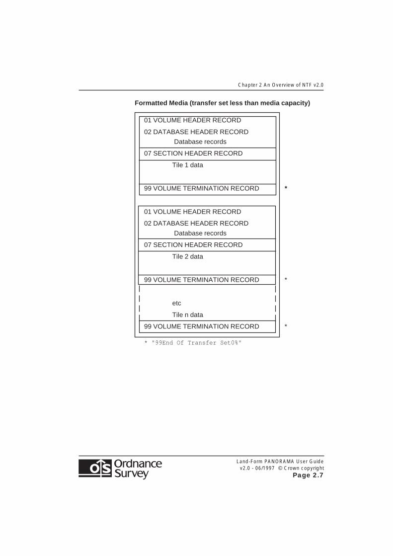
Formatted Media (transfer set less than media capacity)
01 VOLUME HEADER RECORD
02 DATABASE HEADER RECORD
Database records
07 SECTION HEADER RECORD
Tile 1 data
99 VOLUME TERMINATION RECORD *
01 VOLUME HEADER RECORD
02 DATABASE HEADER RECORD
Database records
07 SECTION HEADER RECORD
Tile 2 data
99 VOLUME TERMINATION RECORD *
etc
Tile n data
99 VOLUME TERMINATION RECORD *
* "99End Of Transfer Set0%"

Chapter 2 An Overview of NTF v2.0
Land-Form PANORAMA User Guidev2.0 - 06/1997 © Crown copyright
Page 2.8
Formatted Media (transfer set greater than media capacity)
01 VOLUME HEADER RECORD 01
02 DATABASE HEADER RECORD
Database records
07 SECTION HEADER RECORD
Part Tile 1 data
99 VOLUME TERMINATION RECORD **
** "99End of Volume 01 Transfer Set Continues OnVolume 02 1%"
01 VOLUME HEADER RECORD 02
Remainder Tile 1 data
99 VOLUME TERMINATION RECORD *
01 VOLUME HEADER RECORD 01
02 DATABASE HEADER RECORD
Database records
07 SECTION HEADER RECORD
Tile 2 data
99 VOLUME TERMINATION RECORD *
* "99End Of Transfer Set0%"

Land-Form PANORAMA User Guidev2.0 - 06/1997 © Crown copyright
Page 2.9
Chapter 2 An Overview of NTF v2.0
File Naming Conventions Used● On unformatted media the file is unnamed.
● On formatted media NTF files are identified by{SECT_REF}.NTF where {SECT_REF} is that field within the[SECHREC] record.

Chapter 2 An Overview of NTF v2.0
Land-Form PANORAMA User Guidev2.0 - 06/1997 © Crown copyright
Page 2.10
Land-Form PANORAMA User Guidev2.0 - 06/1997 © Crown copyright
Page 3.1
Chapter 3 Land-Form PANORAMA Data in NTF
Chapter 3 Land-Form PANORAMA Data in NTF
Land-Form PANORAMA Contour Data
Section Data Records
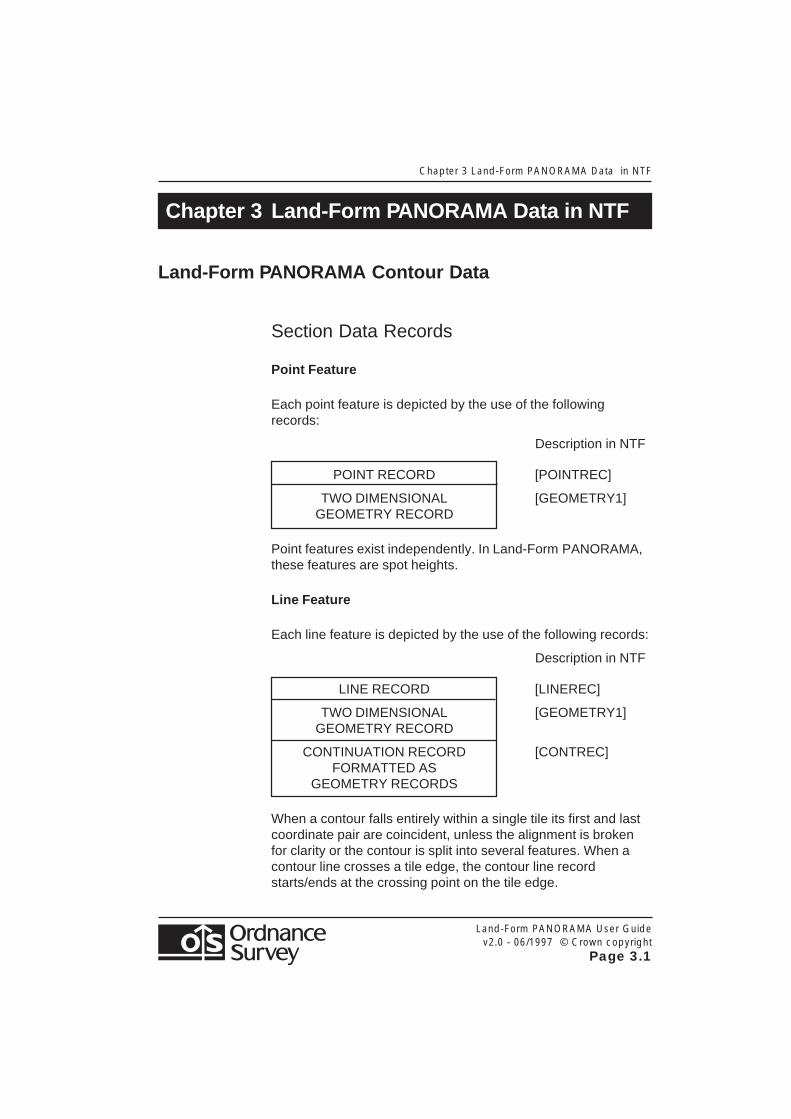
Point Feature
Each point feature is depicted by the use of the followingrecords:
Description in NTF
POINT RECORD [POINTREC]
TWO DIMENSIONAL [GEOMETRY1]GEOMETRY RECORD
Point features exist independently. In Land-Form PANORAMA,these features are spot heights.
Line Feature
Each line feature is depicted by the use of the following records:
Description in NTF
LINE RECORD [LINEREC]
TWO DIMENSIONAL [GEOMETRY1]GEOMETRY RECORD
CONTINUATION RECORD [CONTREC]FORMATTED AS
GEOMETRY RECORDS
When a contour falls entirely within a single tile its first and lastcoordinate pair are coincident, unless the alignment is brokenfor clarity or the contour is split into several features. When acontour line crosses a tile edge, the contour line recordstarts/ends at the crossing point on the tile edge.

Chapter 3 Land-Form PANORAMA Data in NTF
Land-Form PANORAMA User Guidev2.0 - 06/1997 © Crown copyright
Page 3.2
Coordinates
Coordinate values and the number of coordinate pairs in afeature are transferred in the [GEOMETRY1] NTF record.Coordinate pairs that will not fit in the [GEOMETRY1] record areplaced into following Continuation Records [CONTREC].
Each coordinate within the data is expressed as a string of tennumeric characters. Leading zeroes are present to complete theten characters.
All coordinates are measured from the local origin, which is theSouth West corner of a tile.
To convert coordinate data to full National Grid coordinates, addthe coordinates of the feature to those of the South West cornerof the tile. The South West corner coordinates are containedwithin the {X_ORIG} and {Y_ORIG} fields of the Section HeaderRecord [SECHREC].
Feature Codes
The point and line records contain feature codes describing thefeature depicted. The values of these codes and theirdescription are given below:
Feature Code Description
0200 Spot Height0201 Contours0202 Lake0203 Breakline0204 Coastline0205 Ridge line0207 Form line
Land-Form PANORAMA User Guidev2.0 - 06/1997 © Crown copyright
Page 3.3
Chapter 3 Land-Form PANORAMA Data in NTF
Land-Form PANORAMA Digital Terrain Models
Introductory Records for DTMs in NTF v2.0Level Five
These are described on pages 2.2 and 2.3.
Section Data Records
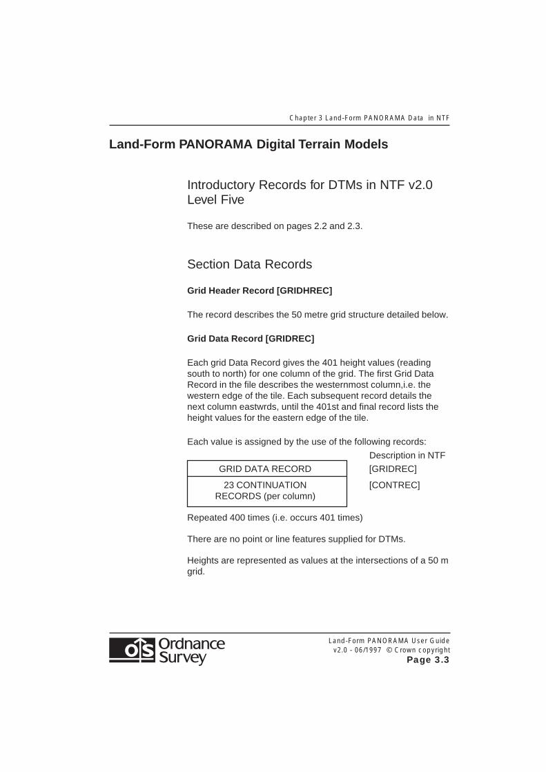
Grid Header Record [GRIDHREC]
The record describes the 50 metre grid structure detailed below.
Grid Data Record [GRIDREC]
Each grid Data Record gives the 401 height values (readingsouth to north) for one column of the grid. The first Grid DataRecord in the file describes the westernmost column,i.e. thewestern edge of the tile. Each subsequent record details thenext column eastwrds, until the 401st and final record lists theheight values for the eastern edge of the tile.
Each value is assigned by the use of the following records:
Description in NTF
GRID DATA RECORD [GRIDREC]
23 CONTINUATION [CONTREC]RECORDS (per column)
Repeated 400 times (i.e. occurs 401 times)
There are no point or line features supplied for DTMs.
Heights are represented as values at the intersections of a 50 mgrid.
Chapter 3 Land-Form PANORAMA Data in NTF
Land-Form PANORAMA User Guidev2.0 - 06/1997 © Crown copyright
Page 3.4
Coordinate System
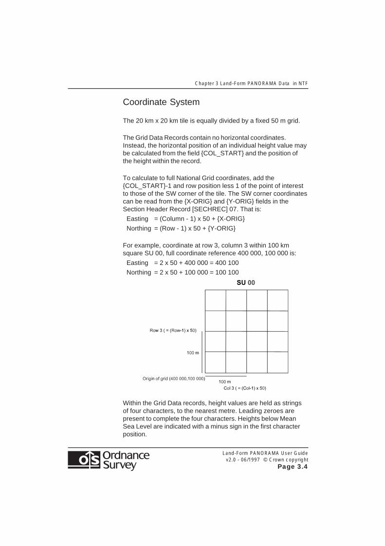
The 20 km x 20 km tile is equally divided by a fixed 50 m grid.
The Grid Data Records contain no horizontal coordinates.Instead, the horizontal position of an individual height value maybe calculated from the field {COL_START} and the position ofthe height within the record.
To calculate to full National Grid coordinates, add the{COL_START}-1 and row position less 1 of the point of interestto those of the SW corner of the tile. The SW corner coordinatescan be read from the {X-ORIG} and {Y-ORIG} fields in theSection Header Record [SECHREC] 07. That is:
Easting = (Column - 1) x 50 + {X-ORIG}
Northing = (Row - 1) x 50 + {Y-ORIG}
For example, coordinate at row 3, column 3 within 100 kmsquare SU 00, full coordinate reference 400 000, 100 000 is:
Easting = 2 x 50 + 400 000 = 400 100
Northing = 2 x 50 + 100 000 = 100 100
Within the Grid Data records, height values are held as stringsof four characters, to the nearest metre. Leading zeroes arepresent to complete the four characters. Heights below MeanSea Level are indicated with a minus sign in the first characterposition.

Land-form PANORAMA User Guidev2.0 - 06/1997 © Crown copyright
Page 4.1
Chapter 4 An overview of DXF
Chapter 4 An Overview of DXF
Introduction
This chapter describes the representation of Land-FormPANORAMA in Ordnance Survey’s implementation of DXFincluding the DXF group and section structure.
General
It is assumed that the reader of this guide is familiar with thesections about DXF in the appropriate AutoCAD manual,published by Autodesk Ltd., Cross Lane, GUILDFORD,GU1 1UJ, or an equivalent document published by the reader’ssoftware supplier if a CAD package other than AutoCAD is to beused.
Overview
Structure of Land-Form PANORAMAContours
Land-Form PANORAMA Contours has a vector ‘point and line’data structure; within this structure a feature may be a point or aline. Each feature is free-standing: its topological relationship toany other feature is not expressed in the data.
Features are classified by type and each type is placed in aseparate DXF layer.

Chapter 4 An Overview of DXF
Land-form PANORAMA User Guidev2.0 - 06/1997 © Crown copyright
Page 4.2
Line Features
A feature is a subjective entity; that is, so long as the constituentlines are of the same description (layer), a feature need not fullydescribe a logical piece of detail. The extent of a feature isdetermined by digitising conventions and will not alwayscoincide with the topology.
Each line feature is composed of a string of coordinate pairs (ortriples) implicitly joined by straight lines. Vector (point and line)data was originally intended for map production.
Structure of Land-Form PANORAMA DTMs
The DTM tiles in DXF consist of a series of heighted pointsarranged on a 50 m grid comprising 401 points by 401 points.
Each of these points have full three dimensional coordinates.
The first point is positioned on the south west corner of the tile,with further points at 50 m intervals northwards to the northernedge of the tile, creating a column of 401 points. The nextcolumn will start on the southern edge of the tile 50 m east ofthe origin, again progressing in 50 m intervals to the north edgeof the tile.
This pattern is repeated until the final point, which falls on thenorth east corner of the tile. Therefore, there are a total of160 801 points on each tile.
Land-form PANORAMA User Guidev2.0 - 06/1997 © Crown copyright
Page 4.3
Chapter 4 An overview of DXF
DXF Layers
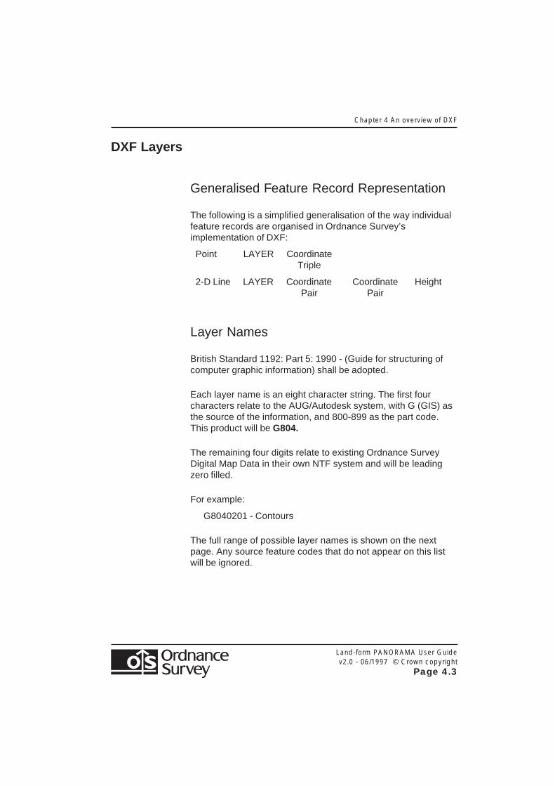
Generalised Feature Record Representation
The following is a simplified generalisation of the way individualfeature records are organised in Ordnance Survey’simplementation of DXF:
Point LAYER CoordinateTriple
2-D Line LAYER Coordinate Coordinate HeightPair Pair
Layer Names
British Standard 1192: Part 5: 1990 - (Guide for structuring ofcomputer graphic information) shall be adopted.
Each layer name is an eight character string. The first fourcharacters relate to the AUG/Autodesk system, with G (GIS) asthe source of the information, and 800-899 as the part code.This product will be G804.
The remaining four digits relate to existing Ordnance SurveyDigital Map Data in their own NTF system and will be leadingzero filled.
For example:
G8040201 - Contours
The full range of possible layer names is shown on the nextpage. Any source feature codes that do not appear on this listwill be ignored.
Chap
ter 4 An O
verview of D
XF
Land-form
PA
NO
RA
MA
User G
uide
v2.0 - 06/1997 © C
rown cop
yright
Pa
ge
4.4
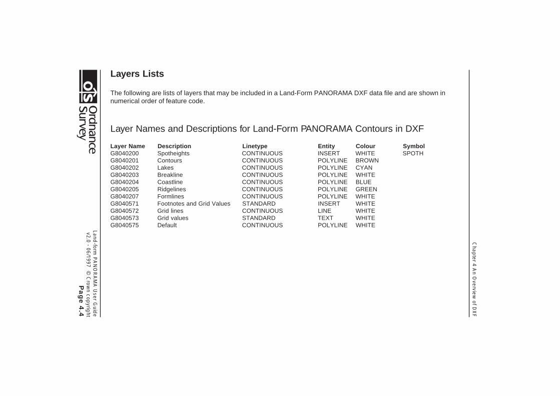
Layers Lists
The following are lists of layers that may be included in a Land-Form PANORAMA DXF data file and are shown innumerical order of feature code.
Layer Names and Descriptions for Land-Form PANORAMA Contours in DXF
Layer Name Description Linetype Entity Colour SymbolG8040200 Spotheights CONTINUOUS INSERT WHITE SPOTHG8040201 Contours CONTINUOUS POLYLINE BROWNG8040202 Lakes CONTINUOUS POLYLINE CYANG8040203 Breakline CONTINUOUS POLYLINE WHITEG8040204 Coastline CONTINUOUS POLYLINE BLUEG8040205 Ridgelines CONTINUOUS POLYLINE GREENG8040207 Formlines CONTINUOUS POLYLINE WHITEG8040571 Footnotes and Grid Values STANDARD INSERT WHITEG8040572 Grid lines CONTINUOUS LINE WHITEG8040573 Grid values STANDARD TEXT WHITEG8040575 Default CONTINUOUS POLYLINE WHITE
Land-form
PA
NO
RA
MA
User G
uide
v2.0 - 06/1997 © C
rown cop
yright
Pa
ge
4.5
Chap
ter 4 An overview
of DX
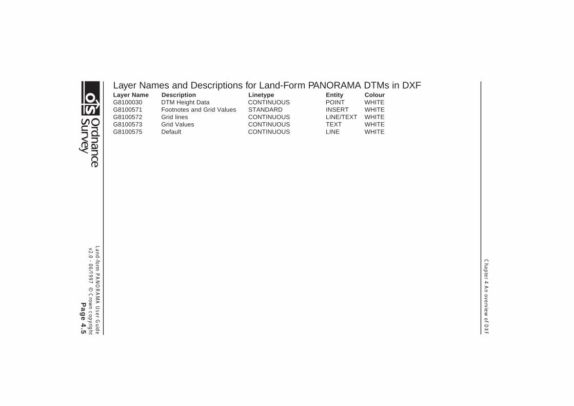
FLayer Names and Descriptions for Land-Form PANORAMA DTMs in DXFLayer Name Description Linetype Entity ColourG8100030 DTM Height Data CONTINUOUS POINT WHITEG8100571 Footnotes and Grid Values STANDARD INSERT WHITEG8100572 Grid lines CONTINUOUS LINE/TEXT WHITEG8100573 Grid Values CONTINUOUS TEXT WHITEG8100575 Default CONTINUOUS LINE WHITE
Chapter 4 An Overview of DXF
Land-form PANORAMA User Guidev2.0 - 06/1997 © Crown copyright
Page 4.6
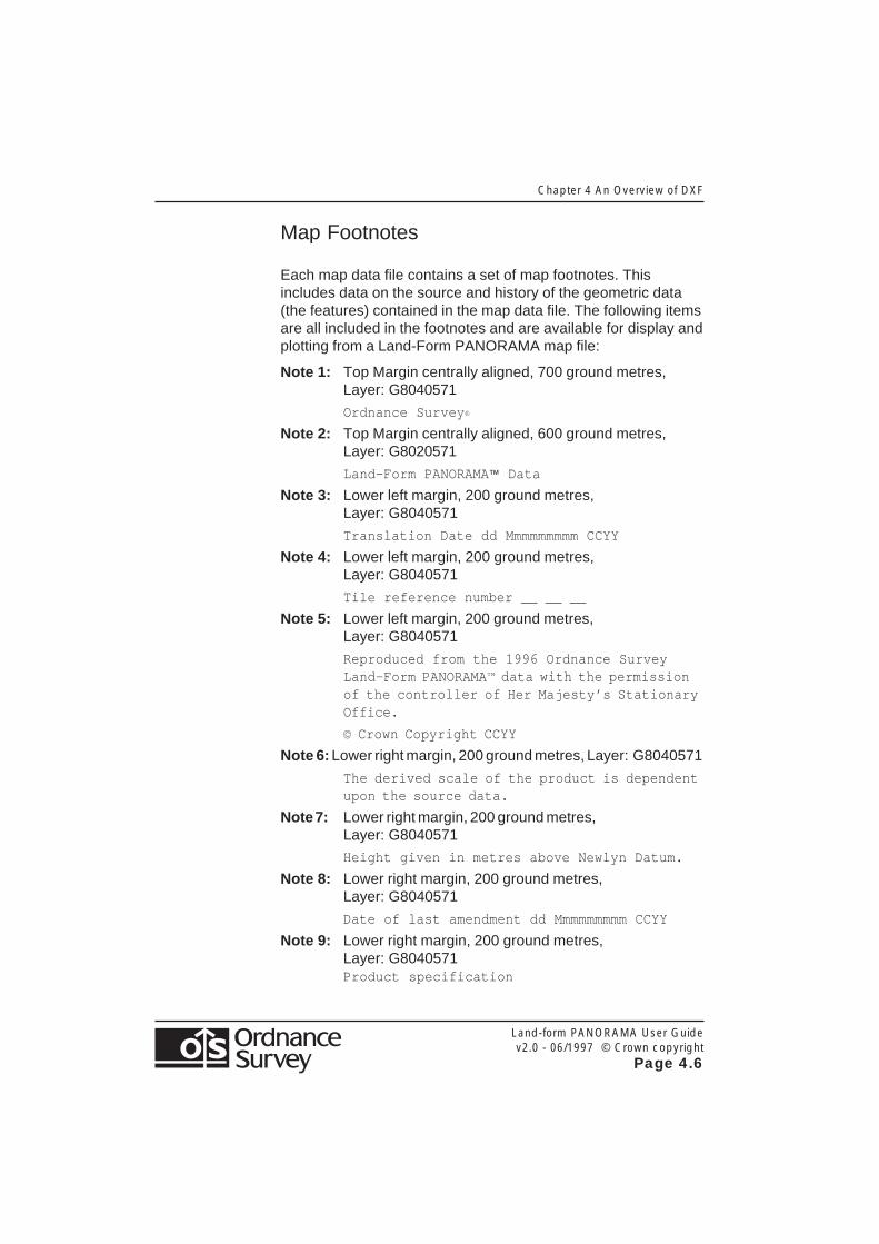
Map Footnotes
Each map data file contains a set of map footnotes. Thisincludes data on the source and history of the geometric data(the features) contained in the map data file. The following itemsare all included in the footnotes and are available for display andplotting from a Land-Form PANORAMA map file:
Note 1: Top Margin centrally aligned, 700 ground metres,Layer: G8040571
Ordnance Survey ®
Note 2: Top Margin centrally aligned, 600 ground metres,Layer: G8020571
Land-Form PANORAMA™ Data
Note 3: Lower left margin, 200 ground metres,Layer: G8040571
Translation Date dd Mmmmmmmmm CCYY
Note 4: Lower left margin, 200 ground metres,Layer: G8040571
Tile reference number __ __ __
Note 5: Lower left margin, 200 ground metres,Layer: G8040571
Reproduced from the 1996 Ordnance SurveyLand-Form PANORAMA™ data with the permissionof the controller of Her Majesty’s StationaryOffice.
© Crown Copyright CCYY
Note 6: Lower right margin, 200 ground metres, Layer: G8040571
The derived scale of the product is dependentupon the source data.
Note 7: Lower right margin, 200 ground metres,Layer: G8040571
Height given in metres above Newlyn Datum.
Note 8: Lower right margin, 200 ground metres,Layer: G8040571
Date of last amendment dd Mmmmmmmmm CCYY
Note 9: Lower right margin, 200 ground metres,Layer: G8040571Product specification

Land-form PANORAMA User Guidev2.0 - 06/1997 © Crown copyright
Page 4.7
Chapter 4 An overview of DXF
Figure 4.1: Layout of Footnotes
6
7
8
9
3
4
5
1
2
Chapter 4 An Overview of DXF
Land-form PANORAMA User Guidev2.0 - 06/1997 © Crown copyright
Page 4.8
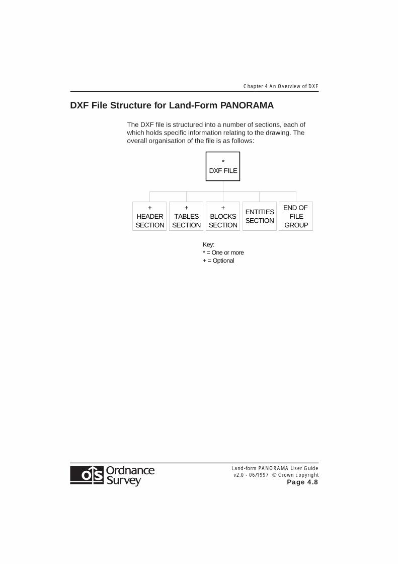
DXF File Structure for Land-Form PANORAMA
The DXF file is structured into a number of sections, each ofwhich holds specific information relating to the drawing. Theoverall organisation of the file is as follows:
+ HEADER SECTION
+ TABLES
SECTION
+ BLOCKS SECTION
ENTITIES SECTION
END OF FILE
GROUP
* DXF FILE
Key: * = One or more + = Optional

Appendix A The National Grid
LAnd-Form PANORAMA User Guidev2.0 - 06/1997 © Crown copyright
Page A.1
Appendix A The National Grid
Land-Form PANORAMA tiles are identified by quoting theNational Grid reference of the south-west corner of the areathey cover. The Ordnance Survey National Grid divides GreatBritain into squares 100 km by 100 km. Each of these squareshas a unique two-letter reference, e.g. TQ in the diagram below.
Each Land-FormPANORAMA 20 kmby 20 km tile isdescribed by adding atwo-digit reference tothe 100 km by 100 kmsquare reference, withthe Easting firstfollowed by theNorthing, e.g. TQ26.
©C
row
n c
op
yrig
ht

Appendix A The National Grid
LAnd-Form PANORAMA User Guidev2.0 - 06/1997 © Crown copyright
Page A.2

Land-Form
PA
NO
RA
MA
User G
uide
v2.0 - 06/1997 © C
rown cop
yright
Pa
ge
B.1
Ap
pend
ix B R
ecord D
efinitions for the Transfer of Land-Form
PA
NO
RA
MA
Contour D
ata in NTF
Appendix B Record Definitions for the Transfer ofLand-Form PANORAMA Contour Data in NTF
NTF Record ListThis list comprises the valid record types used in the NTF v2.0 level 1 Transfer Set Land-Form PANORAMA Contour Data.
Desc Description Record Name
00 Continuation Record - continues a logical record when the physical limit of 80 characters [CONTREC]for other record types is exceeded
01 Volume Header Record - defines the donor and data type [VOLHDREC]
02 Database Header Record - transfers data about the database [DBHREC]
05 Feature Classification Record - defines data classifications (feature codes) [FEATCLASS]
07 Section Header Record - coordinate and structure types, unit scale, factors, etc. [SECHREC]
15 Point Record - identifies the definition of node points [POINTREC]
21 Two-dimensional Geometry Record - defines the two-dimensional geometry for a link or node [GEOMETRY1]
23 Line Record - identifies the definition of a link [LINEREC]
40 Attribute Description Record - defines attribute descriptions and their fields [ATTDESC]
99 Volume Terminator Record - defines the end of the transfer set [VOLTERM]
Note: Desc = descriptor

Ap
pend
ix B R
ecord D
efinitions for the Transfer of Land-Form
PA
NO
RA
MA
Contour D
ata in NTF
Land-Form
PA
NO
RA
MA
User G
uide
v2.0 - 06/1997 © C
rown cop
yright
Pa
ge
B.2
Volume Header Record [VOLHDREC] 01Field Position Format Value Example DescriptionREC_DESC 01:02 A2 01DONOR 03:22 A20 ORDNANCE SURVEY<5S>RECIPIENT 23:42 A20 <20S> Not usedTRANDATE 43:50 D8 19940120 Date of transfer: yyyymmddSERIAL 51:54 I4 0000 Not usedVOLNUM 55:56 I2 01 Volume number 01 to 99NTFLEVEL 57:57 I1 1 NTF Level 1NTFVER 58:61 R4,2 0200 NTF version 2.00NTFOR 62:62 A1 V Variable length recordsEOR 63:63 A1 % % on unformatted media or
<S> Defaults to % for formatted mediaDIVIDER 64:64 A1 \ Divider used to terminate variable length text
fieldsCONT_MARK 65:65 I1 0 No continuation recordEOR 66:66 A1 % ASCII 37
Land-Form
PA
NO
RA
MA
User G
uide
v2.0 - 06/1997 © C
rown cop
yright
Pa
ge
B.3
Ap
pend
ix B R
ecord D
efinitions for the Transfer of Land-Form
PA
NO
RA
MA
Contour D
ata in NTF
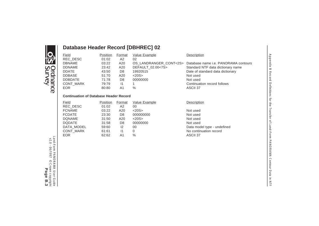
Database Header Record [DBHREC] 02Field Position Format Value Example DescriptionREC_DESC 01:02 A2 02DBNAME 03:22 A20 OS_LANDRANGER_CONT<2S> Database name i.e. PANORAMA contoursDDNAME 23:42 A20 DEFAULT_02.00<7S> Standard NTF data dictionary nameDDATE 43:50 D8 19920515 Date of standard data dictionaryDDBASE 51:70 A20 <20S> Not usedDDBDATE 71:78 D8 00000000 Not usedCONT_MARK 79:79 I1 1 Continuation record followsEOR 80:80 A1 % ASCII 37
Continuation of Database Header Record
Field Position Format Value Example DescriptionREC_DESC 01:02 A2 00FCNAME 03:22 A20 <20S> Not usedFCDATE 23:30 D8 000000000 Not usedDQNAME 31:50 A20 <20S> Not usedDQDATE 31:58 D8 00000000 Not usedDATA_MODEL 59:60 I2 00 Data model type - undefinedCONT_MARK 61:61 I1 0 No continuation recordEOR 62:62 A1 % ASCII 37
Ap
pend
ix B R
ecord D
efinitions for the Transfer of Land-Form
PA
NO
RA
MA
Contour D
ata in NTF
Land-Form
PA
NO
RA
MA
User G
uide
v2.0 - 06/1997 © C
rown cop
yright
Pa
ge
B.4
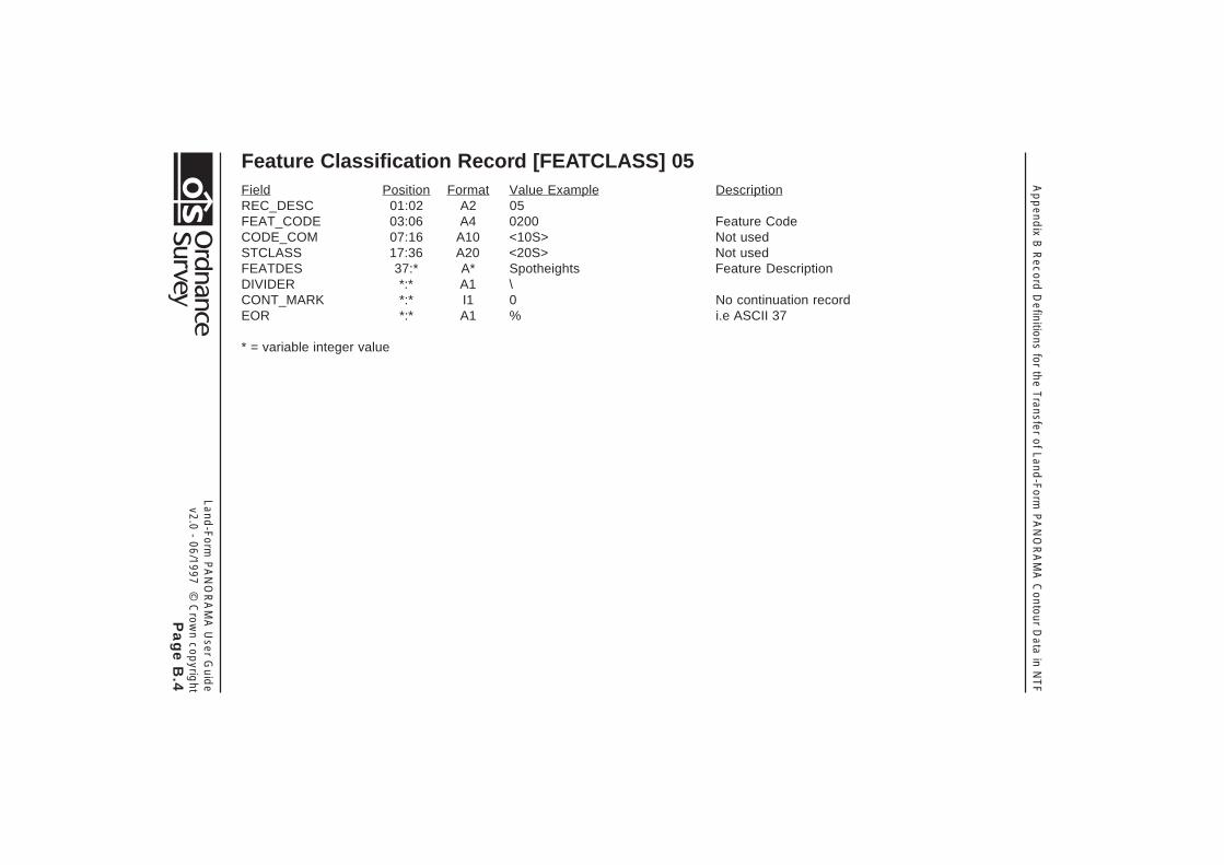
Feature Classification Record [FEATCLASS] 05Field Position Format Value Example DescriptionREC_DESC 01:02 A2 05FEAT_CODE 03:06 A4 0200 Feature CodeCODE_COM 07:16 A10 <10S> Not usedSTCLASS 17:36 A20 <20S> Not usedFEATDES 37:* A* Spotheights Feature DescriptionDIVIDER *:* A1 \CONT_MARK *:* I1 0 No continuation recordEOR *:* A1 % i.e ASCII 37
* = variable integer value
Land-Form
PA
NO
RA
MA
User G
uide
v2.0 - 06/1997 © C
rown cop
yright
Pa
ge
B.5
Ap
pend
ix B R
ecord D
efinitions for the Transfer of Land-Form
PA
NO
RA
MA
Contour D
ata in NTF
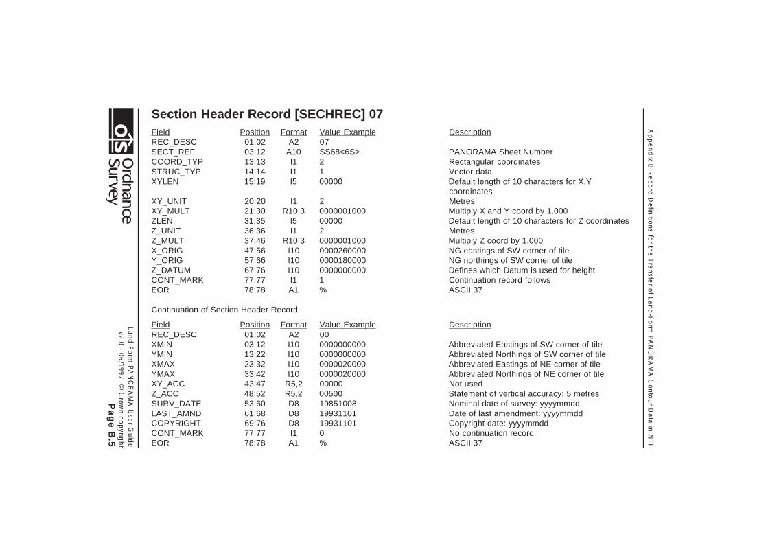
Section Header Record [SECHREC] 07Field Position Format Value Example DescriptionREC_DESC 01:02 A2 07SECT_REF 03:12 A10 SS68<6S> PANORAMA Sheet NumberCOORD_TYP 13:13 I1 2 Rectangular coordinatesSTRUC_TYP 14:14 I1 1 Vector dataXYLEN 15:19 I5 00000 Default length of 10 characters for X,Y
coordinatesXY_UNIT 20:20 I1 2 MetresXY_MULT 21:30 R10,3 0000001000 Multiply X and Y coord by 1.000ZLEN 31:35 I5 00000 Default length of 10 characters for Z coordinatesZ_UNIT 36:36 I1 2 MetresZ_MULT 37:46 R10,3 0000001000 Multiply Z coord by 1.000X_ORIG 47:56 I10 0000260000 NG eastings of SW corner of tileY_ORIG 57:66 I10 0000180000 NG northings of SW corner of tileZ_DATUM 67:76 I10 0000000000 Defines which Datum is used for heightCONT_MARK 77:77 I1 1 Continuation record followsEOR 78:78 A1 % ASCII 37
Continuation of Section Header Record
Field Position Format Value Example DescriptionREC_DESC 01:02 A2 00XMIN 03:12 I10 0000000000 Abbreviated Eastings of SW corner of tileYMIN 13:22 I10 0000000000 Abbreviated Northings of SW corner of tileXMAX 23:32 I10 0000020000 Abbreviated Eastings of NE corner of tileYMAX 33:42 I10 0000020000 Abbreviated Northings of NE corner of tileXY_ACC 43:47 R5,2 00000 Not usedZ_ACC 48:52 R5,2 00500 Statement of vertical accuracy: 5 metresSURV_DATE 53:60 D8 19851008 Nominal date of survey: yyyymmddLAST_AMND 61:68 D8 19931101 Date of last amendment: yyyymmddCOPYRIGHT 69:76 D8 19931101 Copyright date: yyyymmddCONT_MARK 77:77 I1 0 No continuation recordEOR 78:78 A1 % ASCII 37

Ap
pend
ix B R
ecord D
efinitions for the Transfer of Land-Form
PA
NO
RA
MA
Contour D
ata in NTF
Land-Form
PA
NO
RA
MA
User G
uide
v2.0 - 06/1997 © C
rown cop
yright
Pa
ge
B.6
Point Record [POINTREC] 15Field Position Format Value Example DescriptionREC_DESC 01:02 A2 15POINT_ID 03:08 I6 000001 Feature Srial NumberVAL_TYPE 09:10 A2 HT Attribute mnemonicVALUE 11:16 A6 000258 Value of HT (in metres)FEAT_CODE 17:20 A4 0200 Feature codeCONT_MARK 21:21 I1 0 No continuation recordEOR 22:22 A1 % ASCII 37
Two-Dimensional Geometry Record [GEOMETRY1] 21Field Position Format Value Example DescriptionREC_DESC 01:02 A2 21GEOM_ID 03:08 I6 000000 Not usedGTYPE 09:09 A1 2 Point feature: 1, Line feature: 2NUM_COORD 10:13 I4 0005 Number of coordinates, a counter for
{X_COORD}, {Y_COORD} and {Q_PLAN}X_COORD 14:* I10 X coordinate or eastingY_COORD *:* I10 Y coordinate or northingQPLAN *:* AI <S> Not usedCONT_MARK *.* I1 0 No continuation record or
1 Continuation record followsEOR *:* A1 % ASCII 37
The group of records {X_COORDS}, {Y_COORDS} and {QPLAN} may repeat to end of physical record and through one or moreContinuation Records {NUM_COORDS} times.

Land-Form
PA
NO
RA
MA
User G
uide
v2.0 - 06/1997 © C
rown cop
yright
Pa
ge
B.7
Ap
pend
ix B R
ecord D
efinitions for the Transfer of Land-Form
PA
NO
RA
MA
Contour D
ata in NTF
Line Record [LINEREC] 23Field Position Format Value Example DescriptionREC_DESC 01:02 A2 23LINE_ID 03:08 I6 000103 Feature Serial NumberVAL_TYPE 09:10 A2 HT Attribute mnemonicVALUE 11:16 A6 000040 Value of HT (in metres)FEAT_CODE 17:20 A4 0201 Feature codeCONT_MARK 21:21 I1 0 No continuation recordEOR 22.22 A1 % ASCII 37
Attribute Description Record [ATTDESC] 40Field Position Format Value Example DescriptionREC_DESC 01:02 A2 40VAL_TYPE 03:04 A2 HT Attribute mnemonic, e.g. heightFWIDTH 05:07 I3 006 Field width of Attribute ValueFINTER 08:12 A5 I6<3S> Interpretation of Field, e.g. I6ATT_NAME 13:* A* HEIGHT Name given to AttributeDIVIDER *:* A1 \FDESC *:* A* CONTOUR VALUE Textual description of AttributeDIVIDER *:* A1 \CONT_MARK *:* I1 0 No continuation recordEOR *:* A1 % ASCII 37
Ap
pend
ix B R
ecord D
efinitions for the Transfer of Land-Form
PA
NO
RA
MA
Contour D
ata in NTF
Land-Form
PA
NO
RA
MA
User G
uide
v2.0 - 06/1997 © C
rown cop
yright
Pa
ge
B.8
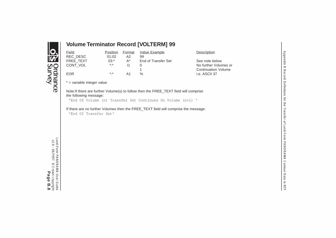
Volume Terminator Record [VOLTERM] 99Field Position Format Value Example DescriptionREC_DESC 01:02 A2 99FREE_TEXT 03:* A* End of Transfer Set See note belowCONT_VOL *:* I1 0 No further Volumes or
1 Continuation VolumeEOR *:* A1 % i.e. ASCII 37
* = variable integer value
Note:If there are further Volume(s) to follow then the FREE_TEXT field will comprisethe following message:
"End Of Volume (n) Transfer Set Continues On Volume (n+l) "
If there are no further Volumes then the FREE_TEXT field will comprise the message:"End Of Transfer Set"

Land-Form
PA
NO
RA
MA
User G
uide
v2.0 - 06/1997 © C
rown cop
yright
Pa
ge
C.1
Ap
pend
ix C R
ecord D
efinitions for the Transfer of Land-Form
PA
NO
RA
MA
DTM
Data in N
TFAppendix C Record Definitions for the Transfer of
Land-Form PANORAMA DTM Data in NTF
NTF Record ListThis list comprises the valid record types used in the NTF v2.0 level 5 Transfer Set for PANORAMA DTMs.
Desc Description Record Name
00 Continuation Record - continues a logical record when the physical limit of 80 characters [CONTREC]for other record types is exceeded
01 Volume Header Record - defines the donor and data type [VOLHDREC]
02 Database Header Record - transfers data about the database [DBHREC]
03 Data Description Record - transfers data dictionary field definitions [DATADESC]
04 Data Format Record - transfers data dictionary record definitions [DATAFMT]
07 Section Header Record - coordinate and structure types, unit scale, factors, etc [SECHREC]
50 Grid header Record - defines DTM grid [GRIDHREC]
51 Grid Data Record - defines DTM height values for grid [GRIDREC]
99 Volume Terminator Record - defines the end of the transfer set [VOLTERM]
Note: Desc = descriptor

Ap
pend
ix C R
ecord D
efinitions for the Transfer of Land-Form
PA
NO
RA
MA
DTM
Data in N
TF
Land-Form
PA
NO
RA
MA
User G
uide
v2.0 - 06/1997 © C
rown cop
yright
Pa
ge
C.2
Volume Header Record [VOLHDREC] 01Field Position Format Value Example DescriptionREC_DESC 01:02 A2 01DONOR 03:22 A20 ORDNANCE SURVEY<5S>RECIPIENT 23:42 A20 <20S> Not usedTRANDATE 43:50 D8 19940120 Date of transfer: yyyymmddSERIAL 51:54 I4 0000 Not usedVOLNUM 55:56 I2 01 Volume number (01 to 99) in transfer setNTFLEVEL 57:57 I1 5 NTF Level 5NTFVER 58:61 R4,2 0200 NTF Version 2.00NTFOR 62:62 A1 V Variable length recordsEOR 63:63 A1 % % on unformatted media
<S> Defaults to % on formatted mediaDIVIDER 64:64 A1 \CONT_MARK 65:65 I1 0 No Continuation recordEOR 66:66 A1 % ASCII 37

Land-Form
PA
NO
RA
MA
User G
uide
v2.0 - 06/1997 © C
rown cop
yright
Pa
ge
C.3
Ap
pend
ix C R
ecord D
efinitions for the Transfer of Land-Form
PA
NO
RA
MA
DTM
Data in N
TFDatabase Header Record [DBHREC] 02Field Position Format Value Example DescriptionREC_DESC 01:02 A2 02DBNAME 03:22 A20 OS_LANDRANGER_DTM<3S> Database name, i.e. PANORAMA DTMDDNAME 23:42 A20 DEFAULT_02.00<7S> Standard NTF data dictionary nameDDATE 43:50 D8 19920515 Date of Standard data dictionaryDDBASE 51:70 A20 <S> Not usedDDBDATE 71:78 D8 00000000 Not usedCONT_MARK 79:79 I1 1 Continuation record followsEOR 80:80 A1 % ASCII 37
Continuation of Database Header Record
Field Position Format Value Example DescriptionREC_DESC 01:02 A2 00FCNAME 03:22 A20 <20S> Not usedFCDATE 23:30 D8 00000000 Not usedDQNAME 31:50 A20 <20S> Not usedDQDATE 51:58 D8 00000000 Not usedDATA_MODEL 59:60 I2 00 Data model type - undefinedCONT_MARK 61:61 I1 0 No continuation recordEOR 62:62 A1 % ASCII 37

Ap
pend
ix C R
ecord D
efinitions for the Transfer of Land-Form
PA
NO
RA
MA
DTM
Data in N
TF
Land-Form
PA
NO
RA
MA
User G
uide
v2.0 - 06/1997 © C
rown cop
yright
Pa
ge
C.4
Data Description Record [DATADESC] 03Field Position Format Value Example DescriptionREC_DESC 01:02 A2 03FIELD_NAME 03:12 A10 GRID_ID Name of field being definedFWIDTH 13:15 I3 010 Width of field being definedFINTER 16:20 A5 I10<2S> Format description if fixed, A* if variableFDESC 21:* A* GRID IDENTITY Textual description of fieldDIVIDER *:* A1 \NO_DATA *:* A* <10S> Field value when no data available. {FWIDTH}
wideDIVIDER *:* A1 \RANGE_MIN *:* *:* <10S> Minimum value for data. {FWIDTH} wideDIVIDER *:* A1 \RANGE_MAX *:* A* <10S> Maximum value for daa. {FWIDTH} wideDIVIDER *:* A1 \UNITS *:* A2 <2S> Not usedCONT_MARK *:* I1 0 No continuation recordEOR *:* A1 % ASCII 37* = variable integer value

Land-Form
PA
NO
RA
MA
User G
uide
v2.0 - 06/1997 © C
rown cop
yright
Pa
ge
C.5
Ap
pend
ix C R
ecord D
efinitions for the Transfer of Land-Form
PA
NO
RA
MA
DTM
Data in N
TFData Format Record [DATAFMT] 04Field Position Format Value Example DescriptionREC_DESC 01:02 A2 04REC_TYPE 03:04 A2 50 {REC_DESC} of Record being definedREC_NAME 05:14 A10 GRIDHREC<2S> Name of record being definedNUM_FIELD 15:16 I2 29 Number of fields in the recordFIELD_NAME *:* A10 GRID_ID,3S> Corresponds to entry in [DATADESC] or
BS7567FUSE *:* A1 c or o Use of field (c=compulsory, o=optional)CONT_MARK *:* I1 1 or 0 Continuation record follows or No Continuation
recordEOR *:* A1 % ASCII 37
Notes: The group of fields {FIELD_NAME} and {FUSE} may repeat to end of physical record and through one or morecontinuation records {NUM_FIELD} times.
The use of brackets within this record around any {FIELD_NAME} and {FUSE} entries indicates that field or group offields may repeat one or more times.
Ap
pend
ix C R
ecord D
efinitions for the Transfer of Land-Form
PA
NO
RA
MA
DTM
Data in N
TF
Land-Form
PA
NO
RA
MA
User G
uide
v2.0 - 06/1997 © C
rown cop
yright
Pa
ge
C.6
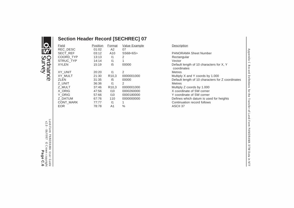
Section Header Record [SECHREC] 07Field Position Format Value Example DescriptionREC_DESC 01:02 A2 07SECT_REF 03:12 A10 SS68<6S> PANORAMA Sheet NumberCOORD_TYP 13:13 I1 2 RectangularSTRUC_TYP 14:14 I1 1 VectorXYLEN 15:19 I5 00000 Default length of 10 characters for X, Y
coordinatesXY_UNIT 20:20 I1 2 MetresXY_MULT 21:30 R10,3 0000001000 Multiply X and Y coords by 1.000ZLEN 31:35 I5 00000 Default length of 10 characters for Z coordinatesZ_UNIT 36:36 I1 2 MetresZ_MULT 37:46 R10,3 0000001000 Multiply Z coords by 1.000X_ORIG 47:56 I10 0000260000 X coordinate of SW cornerY_ORIG 57:66 I10 0000180000 Y coordinate of SW cornerZ_DATUM 67:76 110 0000000000 Defines which datum is used for heightsCONT_MARK 77:77 I1 1 Continuation record followsEOR 78:78 A1 % ASCII 37

Land-Form
PA
NO
RA
MA
User G
uide
v2.0 - 06/1997 © C
rown cop
yright
Pa
ge
C.7
Ap
pend
ix C R
ecord D
efinitions for the Transfer of Land-Form
PA
NO
RA
MA
DTM
Data in N
TFContinuation of Section Header RecordField Position Format Value Example DescriptionREC_DESC 01:02 A2 00XMIN 03:12 I10 0000000000 Abbreviated Eastings of SW corner of tileYMIN 13:22 I10 0000000000 Abbreviated Northings of SW corner of tileXMAX 23:32 I10 0000020000 Abbreviated Eastings of NE corner of tileYMAX 33:42 I10 0000020000 Abbreviated Northings of NE corner of tileXY_ACC 43:47 R5,2 00000 Not usedZ_ACC 48:52 R5,2 00500 Statement of vertical accuracy (5 metres)SURV_DATE 53:60 D8 19850901 Nominal date of survey: yyyymmddLAST_AMND 61:68 D8 19850901 Date of last amendment: yyyymmddCOPYRIGHT 69:76 D8 19850901 Copyright date: yyyymmddCONT_MARK 77:77 I1 0 No continuation recordEOR 78:78 A1 % ASCII 37
Note: The default length of 10 characters will in practice be overwritten by the redefinition of the {X_COORD}, {Y_COORD} and{Z_COORD} fields to a 6 character field in a [DATADESC] 03 record. Please note that the heights at the intersections of the gridare four character fields defined as {GRIDVAL} in a [DATADESC] 03 record.
Ap
pend
ix C R
ecord D
efinitions for the Transfer of Land-Form
PA
NO
RA
MA
DTM
Data in N
TF
Land-Form
PA
NO
RA
MA
User G
uide
v2.0 - 06/1997 © C
rown cop
yright
Pa
ge
C.8
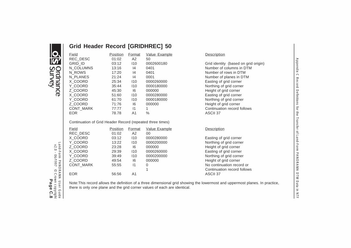
Grid Header Record [GRIDHREC] 50Field Position Format Value Example DescriptionREC_DESC 01:02 A2 50GRID_ID 03:12 I10 0002600180 Grid identity (based on grid origin)N_COLUMNS 13:16 I4 0401 Number of columns in DTMN_ROWS 17:20 I4 0401 Number of rows in DTMN_PLANES 21:24 I4 0001 Number of planes in DTMX_COORD 25:34 I10 0000260000 Easting of grid cornerY_COORD 35:44 I10 0000180000 Northing of grid cornerZ_COORD 45:30 I6 000000 Height of grid cornerX_COORD 51:60 I10 0000280000 Easting of grid cornerY_COORD 61:70 I10 0000180000 Northing of grid cornerZ_COORD 71:76 I6 000000 Height of grid cornerCONT_MARK 77:77 I1 1 Continuation record followsEOR 78.78 A1 % ASCII 37
Continuation of Grid Header Record (repeated three times)
Field Position Format Value Example DescriptionREC_DESC 01:02 A2 00X_COORD 03:12 I10 0000280000 Easting of grid cornerY_COORD 13:22 I10 0000200000 Northing of grid cornerZ_COORD 23:28 I6 000000 Height of grid cornerX_COORD 29:39 I10 0000260000 Easting of grid cornerY_COORD 39:49 I10 0000200000 Northing of grid cornerZ_COORD 49:54 I6 000000 Height of grid cornerCONT_MARK 55:55 I1 0 No continuation record or
1 Continuation record followsEOR 56:56 A1 ASCII 37
Note:This record allows the definition of a three dimensional grid showing the lowermost and uppermost planes. In practice,there is only one plane and the grid corner values of each are identical.
Land-Form
PA
NO
RA
MA
User G
uide
v2.0 - 06/1997 © C
rown cop
yright
Pa
ge
C.9
Ap
pend
ix C R
ecord D
efinitions for the Transfer of Land-Form
PA
NO
RA
MA
DTM
Data in N
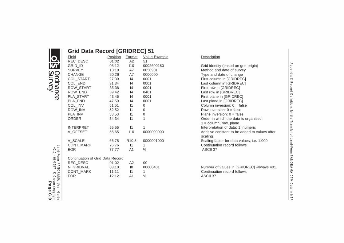
TFGrid Data Record [GRIDREC] 51Field Position Format Value Example DescriptionREC_DESC 01:02 A2 51GRID_ID 03:12 I10 0002600180 Grid identity (based on grid origin)SURVEY 13:19 A7 0850901 Method and date of surveyCHANGE 20:26 A7 0000000 Type and date of changeCOL_START 27:30 I4 0001 First column in [GRIDREC]COL_END 31:34 I4 0001 Last column in [GRIDREC]ROW_START 35:38 I4 0001 First row in [GRIDREC]ROW_END 39:42 I4 0401 Last row in [GRIDREC]PLA_START 43:46 I4 0001 First plane in [GRIDREC]PLA_END 47:50 I4 0001 Last plane in [GRIDREC]COL_INV 51:51 I1 0 Column inversion: 0 = falseROW_INV 52:52 I1 0 Row inversion: 0 = falsePLA_INV 53:53 I1 0 Plane inversion: 0 = falseORDER 54:34 I1 1 Order in which the data is organised:
1 = column, row, planeINTERPRET 55:55 I1 1 Interpretation of data: 1=numericV_OFFSET 56:65 I10 0000000000 Additive constant to be added to values after
scalingV_SCALE 66:75 R10,3 0000001000 Scaling factor for data values, i.e. 1.000CONT_MARK 76:76 I1 1 Continuation record followsEOR 77:77 A1 % ASCII 37
Continuation of Grid Data Record:REC_DESC 01:02 A2 00N_GRIDVAL 03:10 I8 00000401 Number of values in [GRIDREC] -always 401CONT_MARK 11:11 I1 1 Continuation record followsEOR 12:12 A1 % ASCII 37
Ap
pend
ix C R
ecord D
efinitions for the Transfer of Land-Form
PA
NO
RA
MA
DTM
Data in N
TF
Land-Form
PA
NO
RA
MA
User G
uide
v2.0 - 06/1997 © C
rown cop
yright
Pa
ge
C.1
0
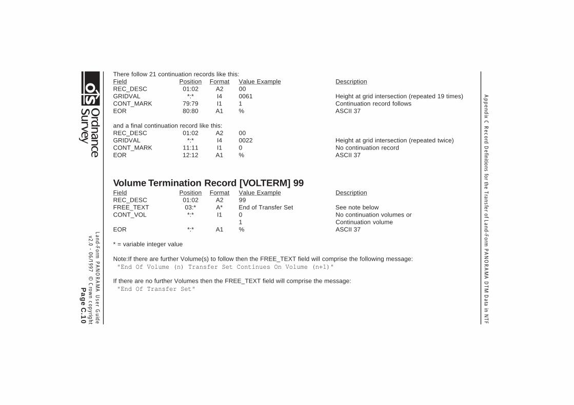
There follow 21 continuation records like this:Field Position Format Value Example DescriptionREC_DESC 01:02 A2 00GRIDVAL *:* I4 0061 Height at grid intersection (repeated 19 times)CONT_MARK 79:79 I1 1 Continuation record followsEOR 80:80 A1 % ASCII 37
and a final continuation record like this:REC_DESC 01:02 A2 00GRIDVAL *:* I4 0022 Height at grid intersection (repeated twice)CONT_MARK 11:11 I1 0 No continuation recordEOR 12:12 A1 % ASCII 37
Volume Termination Record [VOLTERM] 99Field Position Format Value Example DescriptionREC_DESC 01:02 A2 99FREE_TEXT 03:* A* End of Transfer Set See note belowCONT_VOL *:* I1 0 No continuation volumes or
1 Continuation volumeEOR *:* A1 % ASCII 37
* = variable integer value
Note:If there are further Volume(s) to follow then the FREE_TEXT field will comprise the following message:"End Of Volume (n) Transfer Set Continues On Volume (n+1)"
If there are no further Volumes then the FREE_TEXT field will comprise the message:"End Of Transfer Set"

Appendix D Record Definitions for the Transfer of Land-Form PANORAMA Data in DXF
Land-Form PANORAMA User Guidev2.0 - 06/1997 © Crown copyright
Page D.1
Appendix D Record Definitions for the Transferof Land-Form PANORAMA Data inDXF
The following pages contain examples of DXF records withexplanatory notes alongside.
Header Section
A DXF file will commence with a Header Section which willcontain general information about the drawing. Each of thegroups consists of a variable name and an associated value orvalues.
* HEADER VARIABLE GROUP SEQUENCE
SECTION START
o HEADER SECTION
Key * one or more o optional
ENDSEC GROUP
HEADER GROUP SECTION HEADER
Thus: 0SECTION 2HEADER 9$ACADVER AutoCAD drawing database version number 1AC1009 This indicates Release 11 or 12 9$EXTMIN X and Y drawing extents, lower left corner 10nnnnnnn.nn Minimum Eastings, (National Grid coordinates)

Appendix D Record Definitions for the Transfer of Land-Form PANORAMA Data in DXF
Land-Form PANORAMA User Guidev2.0 - 06/1997 © Crown copyright
Page D.2
20nnnnnnn.nn Minimum Northings, (National Grid Coordinates) 9$EXTMAX X and Y drawing extents, upper right corner 10nnnnnnn.nn Maximum Eastings, (National Grid Coordinates) 20nnnnnnn.nn Maximum Northings, (National Grid
Coordinates) 9$LIMMIN X and Y drawing limits, lower left corner 10nnnnnn.n X drawing limit, lower left corner, (in the
AutoCAD World Coordinate System) 20nnnnnn.n Y drawing limit, lower left corner, (in WCS) 9$LIMMAX X and Y drawing limits, upper right corner 10nnnnnn.n X drawing limit, upper right corner, (in WCS) 20nnnnnn.n Y drawing limit, upper right corner, (in WCS) 9$LTSCALE Global linetype scale 40 1.0 9$ATTMODE Attribute visibility 70 1 This sets attributes to ‘on’ when the tile is open 9$FILLMODE Fill mode ‘on’ if non-zero 70 1 9$TEXTSIZE Default text height 40 1.0 9$TEXTSTYLE Current text style name 7STANDARD 9
Appendix D Record Definitions for the Transfer of Land-Form PANORAMA Data in DXF
Land-Form PANORAMA User Guidev2.0 - 06/1997 © Crown copyright
Page D.3
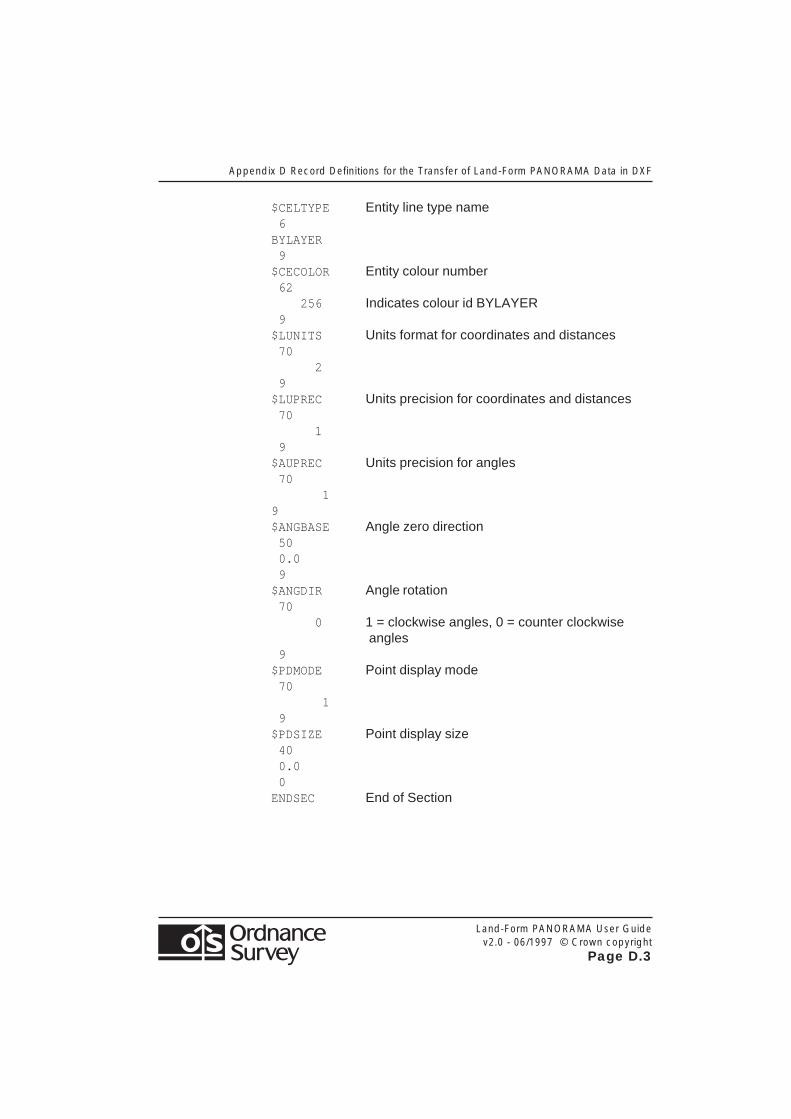
$CELTYPE Entity line type name 6BYLAYER 9$CECOLOR Entity colour number 62 256 Indicates colour id BYLAYER 9$LUNITS Units format for coordinates and distances 70 2 9$LUPREC Units precision for coordinates and distances 70 1 9$AUPREC Units precision for angles 70 19$ANGBASE Angle zero direction 50 0.0 9$ANGDIR Angle rotation 70 0 1 = clockwise angles, 0 = counter clockwise
angles 9$PDMODE Point display mode 70 1 9$PDSIZE Point display size 40 0.0 0ENDSEC End of Section
Appendix D Record Definitions for the Transfer of Land-Form PANORAMA Data in DXF
Land-Form PANORAMA User Guidev2.0 - 06/1997 © Crown copyright
Page D.4
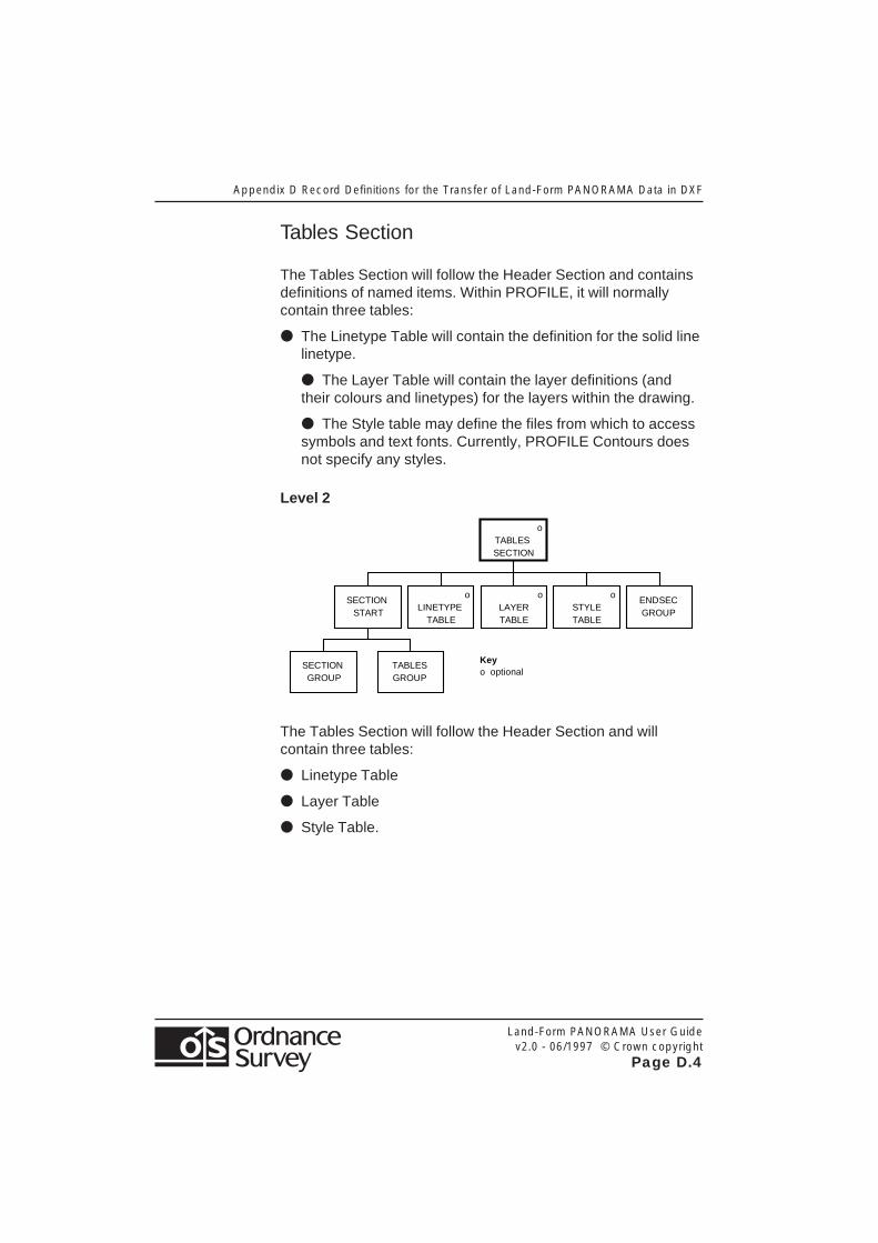
Tables Section
The Tables Section will follow the Header Section and containsdefinitions of named items. Within PROFILE, it will normallycontain three tables:
● The Linetype Table will contain the definition for the solid linelinetype.
● The Layer Table will contain the layer definitions (andtheir colours and linetypes) for the layers within the drawing.
● The Style table may define the files from which to accesssymbols and text fonts. Currently, PROFILE Contours doesnot specify any styles.
Level 2
o LINETYPE
TABLE
SECTION START
o TABLES SECTION
Key o optional
ENDSEC GROUP
TABLES GROUP
SECTION GROUP
o STYLE TABLE
o LAYER TABLE
The Tables Section will follow the Header Section and willcontain three tables:
● Linetype Table
● Layer Table
● Style Table.
Appendix D Record Definitions for the Transfer of Land-Form PANORAMA Data in DXF
Land-Form PANORAMA User Guidev2.0 - 06/1997 © Crown copyright
Page D.5
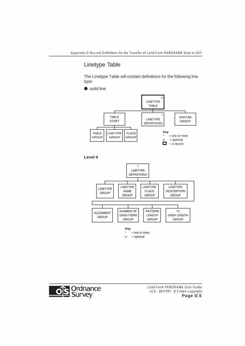
Linetype Table
The Linetype Table will contain definitions for the following linetype:
● solid line
Key * = one or more o = optional = a record
o LINETYPE
TABLE
LINETYPE GROUP
TABLE GROUP
FLAGS GROUP
* LINETYPE
DEFINITIONS
TABLE START
ENDTAB GROUP
Level 4
Key * = one or more o = optional
LINETYPE DESCRIPTION
GROUP
LINETYPE FLAGS GROUP
LINETYPE NAME
GROUP
LINETYPE GROUP
* LINETYPE
DEFINITIONS
ALIGNMENT GROUP
NUMBER OF DASH ITEMS
GROUP
PATTERN LENGTH GROUP
*o DASH LENGTH
GROUP
Appendix D Record Definitions for the Transfer of Land-Form PANORAMA Data in DXF
Land-Form PANORAMA User Guidev2.0 - 06/1997 © Crown copyright
Page D.6
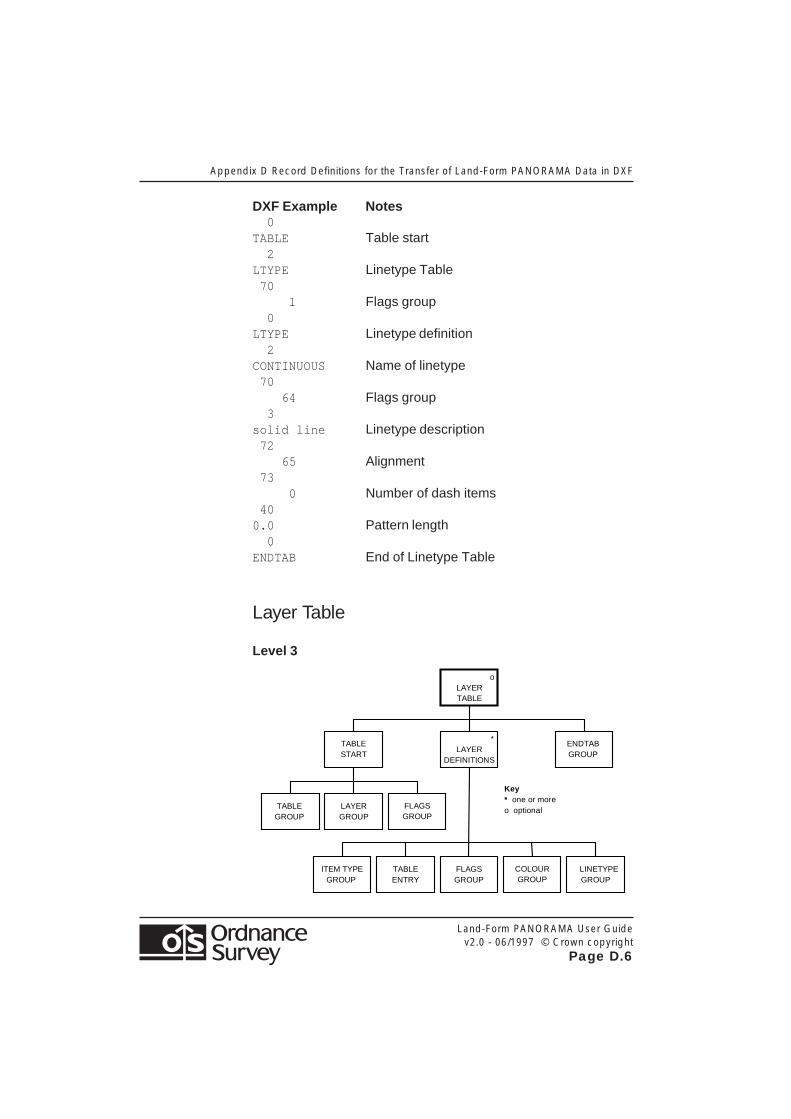
DXF Example Notes 0TABLE Table start 2LTYPE Linetype Table 70 1 Flags group 0LTYPE Linetype definition 2CONTINUOUS Name of linetype 70 64 Flags group 3solid line Linetype description 72 65 Alignment 73 0 Number of dash items 400.0 Pattern length 0ENDTAB End of Linetype Table
Layer Table
Level 3
LINETYPE GROUP
o LAYER TABLE
Key * one or more o optional
ITEM TYPE GROUP
TABLE GROUP
FLAGS GROUP
TABLE ENTRY
* LAYER
DEFINITIONS
LAYER GROUP
FLAGS GROUP
TABLE START
ENDTAB GROUP
COLOUR GROUP
Appendix D Record Definitions for the Transfer of Land-Form PANORAMA Data in DXF
Land-Form PANORAMA User Guidev2.0 - 06/1997 © Crown copyright
Page D.7
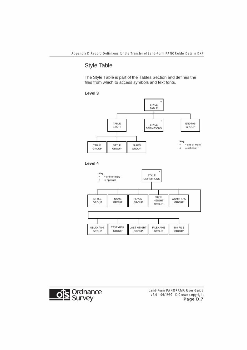
Style Table
The Style Table is part of the Tables Section and defines thefiles from which to access symbols and text fonts.
Level 3
Key * = one or more o = optional
o STYLE TABLE
STYLE GROUP
TABLE GROUP
FLAGS GROUP
* STYLE
DEFINITIONS
TABLE START
ENDTAB GROUP
Level 4
Key * = one or more o = optional
FIXED HEIGHT GROUP
FLAGS GROUP
NAME GROUP
STYLE GROUP
* STYLE
DEFINITIONS
QBLIQ ANG GROUP
LAST HEIGHT GROUP
FILENAME GROUP
WIDTH FAC GROUP
TEXT GEN GROUP
BIG FILE GROUP
Appendix D Record Definitions for the Transfer of Land-Form PANORAMA Data in DXF
Land-Form PANORAMA User Guidev2.0 - 06/1997 © Crown copyright
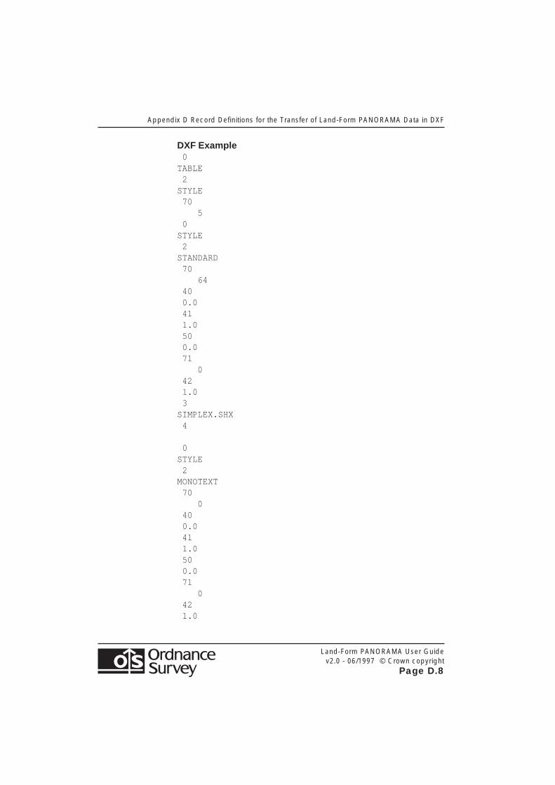
Page D.8
DXF Example 0TABLE 2STYLE 70 5 0STYLE 2STANDARD 70 64 40 0.0 41 1.0 50 0.0 71 0 42 1.0 3SIMPLEX.SHX 4
0STYLE 2MONOTEXT 70 0 40 0.0 41 1.0 50 0.0 71 0 42 1.0

Appendix D Record Definitions for the Transfer of Land-Form PANORAMA Data in DXF
Land-Form PANORAMA User Guidev2.0 - 06/1997 © Crown copyright
Page D.9
3MONOTXT.SHX 4
0STYLE 2MONOTXT 70 0 40 0.0 41 1.0 50 0.0 71 0 42 1.0 3MONOTXT.SHX 4
0ENDTAB

Appendix D Record Definitions for the Transfer of Land-Form PANORAMA Data in DXF
Land-Form PANORAMA User Guidev2.0 - 06/1997 © Crown copyright
Page D.10
Blocks Section
The Blocks Section defines the symbols (or blocks) which mayappear in the drawing. These can be made up from any numberof entities such as polylines.
Level 2
SECTION START
o BLOCKS SECTION
Key * one or more o optional
ENDSEC GROUP
BLOCKS GROUP
SECTION GROUP
* BLOCK
Level 3
Key * one or more o optional
* BLOCK
BLOCK GROUP
BLOCK TYPE FLAG
BLOCK NAME
LAYER GROUP
X GROUP
Z GROUP
Y GROUP
* ENTITIES
ENDBLK GROUP
Appendix D Record Definitions for the Transfer of Land-Form PANORAMA Data in DXF
Land-Form PANORAMA User Guidev2.0 - 06/1997 © Crown copyright
Page D.11
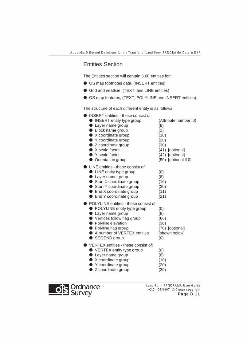
Entities Section
The Entities section will contain DXF entities for:
● OS map footnotes data, (INSERT entities)
● Grid and neatline, (TEXT and LINE entities)
● OS map features, (TEXT, POLYLINE and INSERT entities).
The structure of each different entity is as follows:
● INSERT entities - these consist of:● INSERT entity type group (Attribute number: 0)● Layer name group (8)● Block name group (2)● X coordinate group (10)● Y coordinate group (20)● Z coordinate group (30)● X scale factor (41) [optional]● Y scale factor (42) [optional]● Orientation group (50) [optional if 0]
● LINE entities - these consist of:● LINE entity type group (0)● Layer name group (8)● Start X coordinate group (10)● Start Y coordinate group (20)● End X coordinate group (11)● End Y coordinate group (21)
● POLYLINE entities - these consist of:● POLYLINE entity type group (0)● Layer name group (8)● Vertices follow flag group (66)● Polyline elevation (30)● Polyline flag group (70) [optional]● A number of VERTEX entities [shown below]● SEQEND group (0)
● VERTEX entities - these consist of:● VERTEX entity type group (0)● Layer name group (8)● X coordinate group (10)● Y coordinate group (20)● Z coordinate group (30)
Appendix D Record Definitions for the Transfer of Land-Form PANORAMA Data in DXF
Land-Form PANORAMA User Guidev2.0 - 06/1997 © Crown copyright
Page D.12
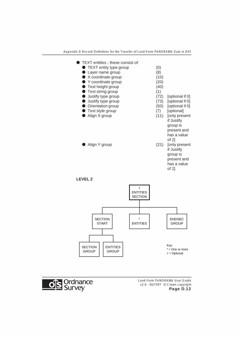
● TEXT entities - these consist of:● TEXT entity type group (0)● Layer name group (8)● X coordinate group (10)● Y coordinate group (20)● Text height group (40)● Text string group (1)● Justify type group (72) [optional if 0]● Justify type group (73) [optional if 0]● Orientation group (50) [optional if 0]● Text style group (7) [optional]● Align X group (11) [only present
if Justifygroup ispresent andhas a valueof 2]
● Align Y group (21) [only presentif Justifygroup ispresent andhas a valueof 2]
LEVEL 2
+ ENTITIES SECTION
* ENTITIES
SECTION START
ENDSEC GROUP
SECTION GROUP
ENTITIES GROUP
Key: * = One or more + = Optional

Appendix D Record Definitions for the Transfer of Land-Form PANORAMA Data in DXF
Land-Form PANORAMA User Guidev2.0 - 06/1997 © Crown copyright
Page D.13
Level 3
* LINE
ENTITY
LINE GROUP
LAYER NAME
GROUP
START X GROUP
START Y GROUP
+ START Z GROUP
END X GROUP
END Y GROUP
+ END Z
GROUP
Key: * = one or more + = optional
Level 3
* INSERT ENTITY
INSERT GROUP
LAYER GROUP
BLOCK NAME
GROUP
X GROUP
Y GROUP
+ Z
GROUP
+ X SCALE FACTOR GROUP
+ Y SCALE FACTOR GROUP
+ Z SCALE FACTOR GROUP
ANGLE GROUP
Key: * = one or more + = optional

Appendix D Record Definitions for the Transfer of Land-Form PANORAMA Data in DXF
Land-Form PANORAMA User Guidev2.0 - 06/1997 © Crown copyright
Page D.14
Level 3
* TEXT
ENTITY
TEXT GROUP
LAYER GROUP
X GROUP
Y GROUP
Z GROUP
TEXT HEIGHT GROUP
STRING GROUP
+ ANGLE GROUP
TEXT STYLE GROUP
+ JUSTIFY
TYPE GROUP
+ ALIGN
X GROUP
+ ALIGN
Y GROUP
Key: * = one or more + = optional
Level 3
POLYLINE GROUP
LAYER GROUP
VERTICES FOLLOW
FLAG GROUP
* VERTICES
SEQ END GROUP
X GROUP
Y GROUP
Z GROUP
+ POLYLINE
FLAG GROUP
* POLYLINE
ENTITY
Key: * = one or more + = optional
Appendix D Record Definitions for the Transfer of Land-Form PANORAMA Data in DXF
Land-Form PANORAMA User Guidev2.0 - 06/1997 © Crown copyright
Page D.15
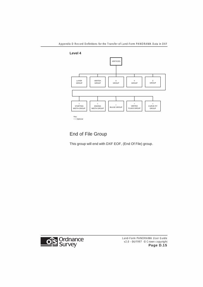
Level 4
VERTICES
LAYER GROUP
VERTEX GROUP
X GROUP
Y GROUP
Z GROUP
+ STARTING
WIDTH GROUP
+ ENDING
WIDTH GROUP
+ BULGE GROUP
+ VERTEX
FLAGS GROUP
+ CURVE FIT
GROUP
Key: + = Optional
End of File Group
This group will end with DXF EOF, (End Of File) group.

Appendix D Record Definitions for the Transfer of Land-Form PANORAMA Data in DXF
Land-Form PANORAMA User Guidev2.0 - 06/1997 © Crown copyright
Page D.16

Appendix E Terms and Conditions
Land-Form PANORAMA User Guidev2.0 - 06/1997 © Crown copyright
Page E.1
Appendix E Terms and Conditions
The following give a brief guide to the terms and conditions ofsupply and use of Land-Form PANORAMA. A full description isdetailed in the signed customer contract held by yourorganization.
Use of Land-Form PANORAMA
Land-Form PANORAMA is supplied under annual paymentarrangements. An initial supply fee is charged for the first year- a lower annual fee is charged for each subsequent year of use.
The fee includes use on up to 50 visual display terminals and upto 5000 hard copies, including internal-use copyright fees.
Copyright of Land-Form PANORAMA is retained by OrdnanceSurvey for 50 years from the end of the year the data was fixed.
Delivery of Land-Form PANORAMA
Customers are advised to copy the supplied data to a back-upmedium.
Written notification of any deficiency in the data or damage tothe goods must be given to Ordnance Survey within 28 days ofreceipt of Land-Form PANORAMA.
Invoice
Payment in full, of the amount shown on the invoice, is due 30days after the invoice date. The only exception is whereOrdnance Survey have agreed extended terms with a customer.

Appendix E Terms and Conditions
Land-Form PANORAMA User Guidev2.0 - 06/1997 © Crown copyright
Page E.2
Copyright
All Ordnance Survey Digital Map Data are Crown copyright. Fulldetails of the conditions under which Ordnance Survey DigitalMap Data may be processed/manipulated or copied by acustomer – whether or not for use on visual terminals or formaking hard copies – are contained in Ordnance Survey leaflet:Copyright 3 - Digital Map Data. These are available fromCopyright, please see below. Users should check the terms andconditions with Ordnance Survey before using the data. It is alsothe responsibility of the holder of the Digital Map Data to ensurethat any output contains the required copyrightacknowledgement.
No part of this document may be reproduced or transmitted inany form or by any means, electronic or mechanical, for anypurpose, without the express written permission of OrdnanceSurvey.
© Crown copyright
CopyrightOrdnance SurveyRomsey RoadSOUTHAMPTONSO16 4GU
Telephone 01703 792684Fax 01703 792535

Appendix F Product Performance Report Form
Land-Form PANORAMA User Guidev2.0 - 06/1997 © Crown copyright
Page F.1
Appendix F Product Performance Report Form
Please photocopy and send completed to:
Ordnance SurveyLand-Form Products ManagerRomsey RoadSOUTHAMPTONSO16 4GU
Type of Data (delete as appropriate):
PANORAMA Contours/DTMs
Problem description/suggestion for:
....................................................................................................
....................................................................................................
....................................................................................................
....................................................................................................
....................................................................................................
....................................................................................................
....................................................................................................
....................................................................................................
....................................................................................................
Quotation/Order Ref: ...........................................................
Your Name: ...........................................................
Company: ...........................................................
Address: ...........................................................
...........................................................
...........................................................
...........................................................
...........................................................
Tel: ....................................... Fax: .......................................

Appendix F Product Performance Report Form
Land-Form PANORAMA User Guidev2.0 - 06/1997 © Crown copyright
Page F.2