Embed Size (px)
Citation preview
lANDSInterdisziplinäre ArbeitsgruppeNaturwissenschaft, Technik und SicherheitspolitikInterdisciplinary Research Group in Science, Technology and Security Policy
ArbeitsberichtWorking Paper
IANUS-2/1990
Uwe ReichettWARHEAODEVELOPMENTAND
NUCLEARTESTING
IANUS, elo Institut fiixKernphysik, Technische Hochschule Darmstadt,Schloßgartenstr. 9, D-6100 Darmstadt, West Germany
Tel.: 06151-163016, -162480
IANUSInterdisziplinäre ArbeitsgruppeNaturwissenschaft, Technik und SicherheitspolitikInterdiaciplinary Research Group in Science. Technology and Security Policy
Arbeitsbericht
Working" Paper
IANUS-2/1990
Uwe ReichertWARHEAD.·DEVELOPMENT ··AND
NUCLEAR TESTING
IANUS, c/o Institut für Kernphysik, Technische Hochschule Darmstadt,Schloßgartenstr. 9,D-6100 Darmstadt, West Germany
Tel.: 06151-163016, -162480
Warhead Development and Nuclear Testing
Uwe Reichert*
17 May 1990
Note
This working paper is a draftversion of Chapter 3 of the study "Nuclear Testingand aComprehensive Test. Ban - Background and Issues". This study was funded by a grant of theVolkswagen Foundation. The author requests readers to advise him ofanyerrors containedin this draftand of new information.
"'lANDS, c/o Institut für Kernphysik, TH Darmstadt, Schlossgartenstr. 9, D-6100 Darmstadt.Current address:Spektrum der Wissenschaft, Mönchhofstrasse 15, D-6900 Heidelberg
1
Contents
1 The D.S. Nuclear Weapons Development and Production Complex1.1 Overview .1.2 The NuclearWeapons Laboratories .1.3 The Material Production Facilities1.4 The Warhead Production Facilities .
2 D .S. Nuclear Warheads -Design and Development Program2.1 Military Characteristics of Warheads2.2 The Life Cycle of Warheads .
3 N uclear Testing3.1 Nuclear Test Sites
3.1.1 United States3.1.2 Soviet Union3.1.3 United Kingdom3.1.4 France.3.1.5 China .3.1.6 India .
3.2 Types and Purposes of Nuclear Tests.3.3 Conducting an underground nuclear test .3.4 Yield Determination .
3.4.1 Radiochemical Method .3.4.2 Methods Using Nuclear And Thermal Radiation Measurements .3.4.3 Hydrodynamical Methods3.4.4 Seismic Methods . . .
2
3368
10
121213
161616252829313131353940404145
1 The U.S. Nuclear Weapons Development and ProductionComplex
1.1 Overview
Since 1977, all nuclear-warhead activities of the United States are overseen by the Departmentof Energy (DOE). The predecessor agencies of the DOE were the ManhattanEngineer District(MED, 1942-46), the Atomic Energy Commission (AEC, 1947-74), and the Energy Research andDevelopment Administration (ERDA, 1975-77). The DOE's responsibility for research, development, testing, production, retirement, and assessment of the reliability of nuclear weapons sternsfrom the Atomic Energy Act of 1954, and has been continued under the DOE Organization Act.
Two formal documents provide guidelines for these nuclear weapons activities. The NuclearWeapons Stockpile Memorandum, an annual document developed jointly by the Departments ofDefense and Energy, that must be approved by the President, establishes the year-end quantities for each warhead type in the nuclear weapons stockpile and authorizes the production andretirement of warheads necessary to achieve and· maintain those quantities.1 This document "isthe mechanism from which (the DOEJ draws [itsJ authority for the specifics of [itsJ program" .2
The second document, the Underground Nuclear Test Program, which also receives Presidentialapproval, authorizes the specific nuclear tests to be conducted each year.3
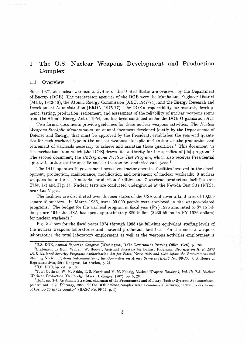
The DOE operates 19 government-owned contractor-operated facilities involved in the development, production, maintenance, modification and retirement of nuclear warheads: 3 nuclearweapons laboratories, 9 material production facilities and 7 warhead production facilities (seeTabs. 1-3 and Fig. 1). Nuclear tests are conducted underground at the Nevada Test Site (NTS),near Las Vegas.
The facilities are distributed over thirteen states of the USA and cover aland area of 10,000square kilometers. In March 1985, some 90,000 people were employed in the weapon-relatedprograms.4 The budget for the warhead program in fiscal year (FY) 1986 amounted to $7.15 billion; since 1940 the USA has spent approximately $89 billion ($230 billion in FY 1986 dollars)for nuclear warheads.5
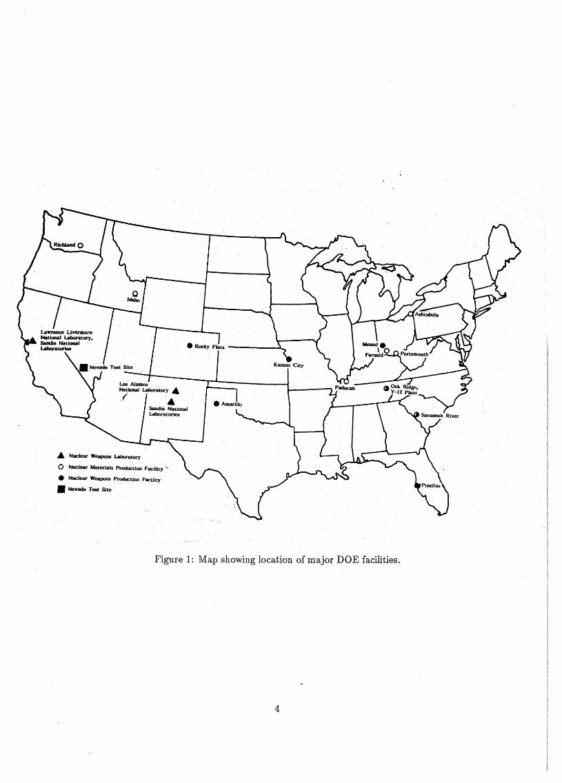
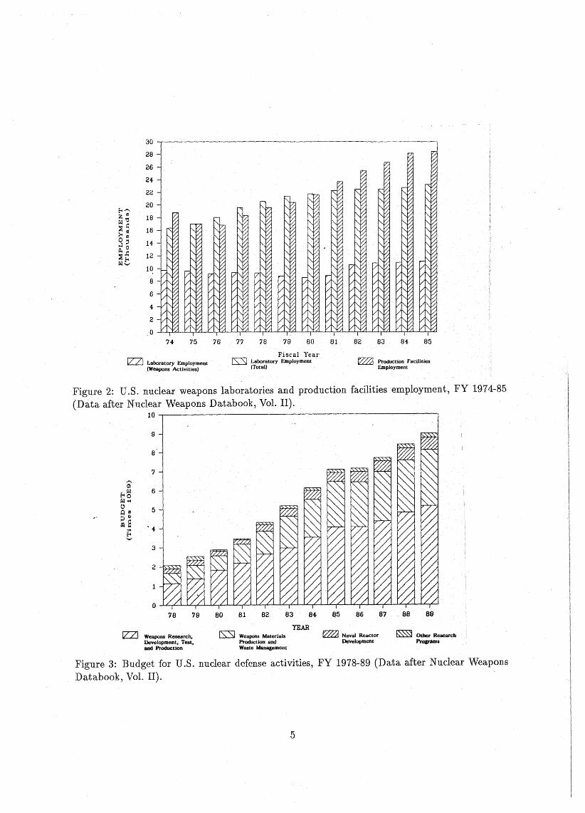
Fig. 2 shows for the fiscal years 1974 through 1985 the fuIl-time equivalent staffing levels ofthe nuclear weapons laboratories and material production facilities. For the nuclear weaponslaboratories the totallaboratory employment aswell as theweapons activitiesemployment is
lU.S. DOE, Annual Report to Congress (Washington, D.C.: GovernmentPrinting Office, 1986), p. 180.2Statement by Hon. William W. Hoover, Assistant Secretary for Defense Programs, Hearings on H. R. 1873
DOE National Security Programs Authorization Act for Fiscal Years 1986 and 1987 before the Procurement andMilitary Nuclear Systems Subcommittee of the Committee on Armed Services (HASe No. 99-13), D.S. House ofRepresentatives, 99th Congress, 1st Session, p. 27.
3U.S. DOE, op. cit., p. 180.4T.B. Cochran, W. M. Arkin, R. S. Norris and M. M. Hoenig, Nuclear Weapons Databook, Vol.lI: U.S. Nuclear
Warhead Production (Cambridge, Mass.: Ballinger, 1987), pp. 5, 28.5Ibid., pp. 2-4; As SamuelStratton, chairman of the Procurement and Military Nuclear Systems Subcommittee,
pointed out on 20 February, 1985: "H the DOE defense complex were a commercial industry, it would rank as oneof the top 20 in the country" (HASC No. 99-13, p. 1).
3
A Nuclear Weapons Laboratory
o Nuclear Materials Production Facility'
• Nuclear Weapons Production Facility
• Nevada Test Site
Figure 1: Map showing Ioeation of major DOE facilities.
4
30 -,----------------------------
28
26
24
22
20
18
16
14
12
10
8
6
4
2
O--l;-Y-'U-J;...;,LI:.L-L.IY-'~....J.,_=L..a.......L...l.,..ILL.L....y:.a-L..l.~L..L..J...,_'lLL.LL,.uJi.....L.l.,.XLL.LL,.:rLl.-L.L,.UJ
74 75 76 77 78 79 80 81 82 83 84 85
l2:Zl Laboratory Employment(Weapons Activitiesl
Fiscal YearlS:SJ Laboratory Employment
(Total)f222d Production Faciüties
Employment
Figure 2: U.S. nuclear weapons laboratories and production facilities employment, FY 1974-85(Data after NuclearWeapons Databook, Vol.· II).
10 -r-----------------------------,
9
8
7
'"Cl>
t-~ 6r.:l.-l~ 5Cl flP 4l
trl 8 '4-8'-'
3
2
78 79 80 81 82 83 84 85 86 87 88 89
Weapons Research,Development, Test,arid Productlon
l:s:::sJ Weapons MaterialsProduction andWaste Management
YEARf2221 Naval Reactor
Devetopment~ Otber Research
Pr08fiUDS
Figure 3: Budget for U.S. nuclear defense activities, FY 1978-89 (Data after Nuclear WeaponsDatabook, Vol. II),
5
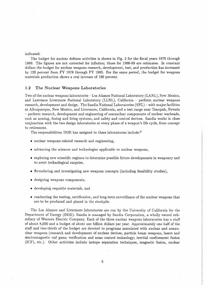
indicated.The budget for nucleardefense activities is shown in Fig. 3 for the fiscal years 1978 through
1989. The figures are not corrected for inflation; those for 1986-89 are estimates. In constantdollars the budget for nuclear weapons research, development, test, and production has increasedby 120 percent from FY 1978 through FY 1985. For the same period, the budget for weaponsmaterials production shows areal increase of 190 percent.
1.2 The Nuclear Weapons Laboratories
Two ofthe nuclear weapons laboratories - Los Alamos National Laboratory (LANL), New Mexico,and Lawrence Livermore National Laboratory (LLNL), California - perform nuc1ear weaponsresearch, development and design. The Sandia National Laboratories (SNL) - with majorfacilitiesat Albuquerque, New Mexico, and Livermore, California, and a test range neat Tonopah, Nevada- perform research, development and engineering of nonnuclear components of nuclear warheads,such as arming, fusing and firing systems, and safety and control devices. Sandia works in eloseconjunction with the two design laboratories at every phase of a weapon's life cycle, from conceptto retirement.
The responsibilities DOE has assigned to these laboratories include:6
• nuclear weapons-related research and engineering,
• advancing the sciences and technologies applicable to nuelear weapons,
• exploring new scientific regimes to determinepossible future developments in weaponry andto avert technological surprise,
• fbrmulating and investigating new weapons concepts (ineluding feasibility studies),
• designing weapons components,
• developing requi8i~e materiais, and
• conducting the testing, certification, and long-term surveillance of the nuelear weapons thatare to be produced and placed in the stockpile.
The Los Alamos and Livermore laboratories are run by the University of California for theDepartment of Energy (DOE). Sandia ismanaged by Sandia Corporation, a wholly owned subsidiary of Western Electric Company. Each of the three nuclear weapons laboratories has a staffof about 8,000 and a budget of about one billion dollars per year. Approximately one half of thestaff and two-thirds of the budget are devoted to programs associated with nuclear and nonnuclear weapons (research and development ofnuclear devices, particle beam weapons, lasers andelectromagnetic raH guns; verification and arms control technology; inertial confinement fusion(ICF), etc.). Other activities include isotope separation techniques, magnetic fusion, nuelear
6
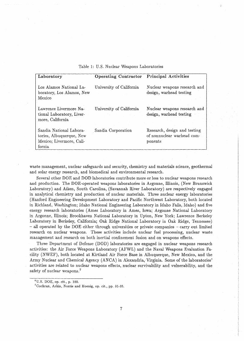
Laboratory
Table 1: U.S. Nuc1ear Weapons Laboratories
Operating Contractor Principal Activities
Los Alamos National Laboratory, Los Alamos, NewMexico
Lawrence Livermore National Laboratory,Livermore, California
Sandia National Laboratories, Albuquerque, NewMexicoj Livermore, California
University of California Nuc1ear weapons research anddesign, warhead testing
University of California Nuclear weapons research anddesign, warhead testing
Sandia Corporation Research, design and testingof nonnuc1ear warhead components
waste management, nuc1ear safeguards and security, chemistry and materials science, geothermaland solar energy research, and biomedical and environmental research.
Several other DOE and DOD laboratories contribute more or less to nuc1ear weapons researchand production. The DOE-operated weapons laboratories in Argonne, lllinois, (New BrunswiekLaboratory) and Aiken, South Carolina, (Savannah .River Laboratory) are respectively engagedin analytical chemistry and production of nuc1ear materials. Three nuc1ear energy Iaboratories(Hanford Engineering Development Laboratory and Pacific Northwest Laboratory, both locatedin Richland, Washington; Idaho National Engineering Laboratory in Idaho Falls, ldaho) and fiveenergy research laboratories (Ames Laboratory in Arnes, lowa; Argonne National Laboratoryin Argonne, lllinois; Brookhaven National Laboratory in Upton, New York; Lawrence BerkeleyLaboratory in Berkeley, California; Oak Ridge National Laboratory in Oak Ridge, Tennessee)- all operated by the DOE either through universities or private companies - carry out limitedresearch on nuc1ear weapons. These activities include nuclear fuel processing, nuc1ear wastemanagement and research on both inertial confinement fusion and on weapons effects.
Three Department of Defense (DOD) laboratories are engaged in nuc1ear weapons researchactivities: the Air Force Weapons Laboratory (AFWL) and the Naval Weapons Evaluation Facility (NWEF), both located at Kirtland Air Force Base in Albuquerque, New Mexico, and theArmy Nuc1ear and Chemical Agency (ANCA) in Alexandria,· Virginia. Some of the laboratories 'activities are related to nuc1ear weapons effects, nuclear survivability and vulnerability, and thesafety of nuc1ear weapons.7
6U.S. DOE, op. cit., p. 180.7Cochran, Arkin, Norris and Hoenig, op. cit., pp. 31-35.
7
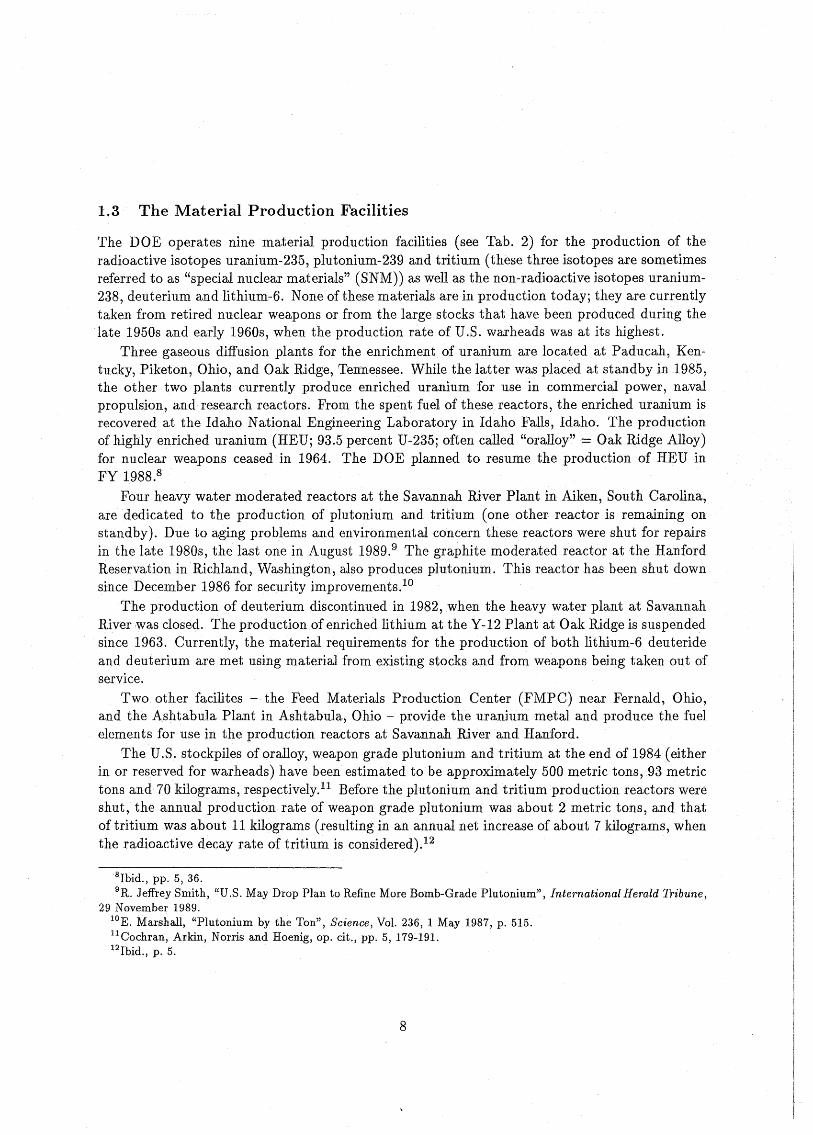
1.3 The Material Production Facilities
The DOE operates nine material production facilities (see Tab. 2) for the production of theradioactive isotopes uranium-235, plutonium-239 and tritium (these three isotopes are sometimesreferred to as "special nuclear materials" (SNM)) as well as the non-radioactive isotopes uranium238, deuterium and lithium-6.None of these materials are in production today; they are currentlytaken from retired nuclear weapons or from the large stocks thathave been produced during thelate 1950s and early 1960s, when the production rate of U.S. warheads Was at its highest.
Three gaseous diffusion plants for the enrichment of uranium are located at Paducah, Kentucky, Piketon, Ohio, and Oak Ridge, Ten'1lessee. While the latter was placed at standby in 1985,the other two plants currently produce enriched uranium for use in commercial power, navalpropulsion, and research reactors. From the spent fuel of these reactors, the enriched uranium isrecovered at the Idaho National Engineering Laboratory in Idaho Falls, Idaho. The productionof highly enriched uranium (HEUj 93.5 percent U-235j often called "oralloy" = Oak Ridge Alloy)for nuclear weapons ceased in 1964. The DOE planned to resume the production of HEU inFY 1988.8
Four heavy water moderated reactors at the Savannah River Plant in Aiken, South Carolina,arededicated to the production of plutonium and tritium (one other reactor is remaining onstandby). Due to aging problems and environmental concern these reactors were shut for repairsin the late 1980s, the last one in August 1989,9 The graphite moderated reactor at the HanfordReservation inRichland,Washington, also produces plutonium. This reactor has been shut downsince December 1986 for security improvements. lO
The production of deuterium discontinued in 1982, when the heavy water plant at SavannahRiver,was closed. The production of enriched lithium at the Y-12 Plant at Oak Ridgeis suspendedsince 1963. Currently, the material requirements for the production of both lithium-6 deuterideand deuterium are met using material from existing stocks and from weapons being taken out ofservice.
Two other facilites - the Feed Materials Production Center (FMPC) near Fernald, Ohio,and the Ashtabula Plant in Ashtabula, Ohio - provide the uranium metal and produce the fuelelements for use in the production reactors at Savannah River and Hanford.
The U.S. stockpiles of oralloy, weapon grade plutonium and tritium at the end of 1984 (eitherin or reserved for warheads) have been estimated to be approximately 500 metric tons, 93 metrictons and 70 kilograms, respectively,l1 Before the plutonium and tritium production reactors wereshut, the annual production rate of weapon grade plutonium was about 2 metric tons, and thatof tritium was about 11 kilograms (resulting in an annual net increase of about 7 kilograms, whenthe radioactive decay rate of tritium is considered).12
8Ibid., pp. 5, 36.9R. Jeffrey Smith, "U.S. May Drop Plan to Refine More Bomb-Grade Plutonium", International Herald Tribune,
29 November 1989.lOE. Marshall, "Plutonium by the Ton", Science, Vol. 236, 1 May 1987, p. 515.llCochran, Arkin, Norris and Hoenig, op. cit., pp. 5, 179-191.12Ibid., p. 5.
8
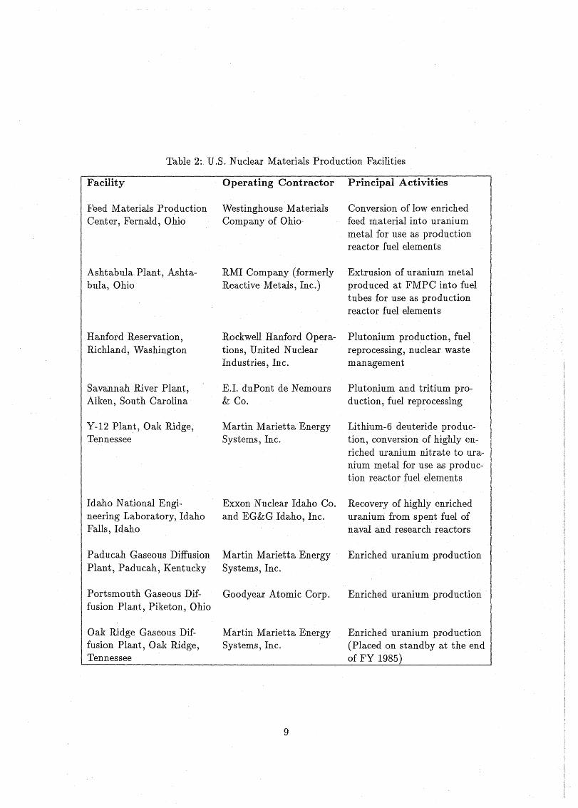
Table 2: U.S. Nuclear Materials Production Facilities
Facility
Feed Materials ProduetionCenter, Fernald, Ohio
Ashtabula Plant, Ashtabula, Ohio
Hanford Reservation,Riehland, Washington
Savannah River Plant,Aiken, South Carolina
Y-12 Plant, Oak Ridge,Tennessee
Idaho National Engineering Laboratory, IdahoFalls, Idaho
Padueah Gaseous DiffusionPlant, Padueah,Kentueky
Portsmouth Gaseous Diffusion Plant, Piketon, Ohio
Oak Ridge Gaseous Diffusion Plant, Oak Ridge,Tennessee
Operating Contractor
Westinghouse MaterialsCompany of Ohio
RMI Company (formerlyReaetive Metals, Ine.)
Roekwell Hanford Operations, United NuclearIndustries, Ine.
E.I. duPont de Nemours& Co.
Martin Marietta EnergySystems, Ine.
Exxon Nuclear Idaho Co.and EG&G Idaho, Ine.
Martin Marietta EnergySystems, Ine.
Goodyear Atomic Corp.
Martin Marietta EnergySystems, Ine.
9
Principal Activities
Conversion of low enriehedfeed material into uraniummetal for use as produetionreaetor fuelelements
Extrusion of uranium· metalprodueed at FMPC into fueltubes for use as produetionreaetor fuel elements
Plutonium produetion, fuelreproeessing, nuclear wastemanagement
Plutonium and tritium production, fuel reproeessing
Lithium-6 deuteride produetion, eonversion of highly enriched uranium nitrate to uranium metal for use as produetion reaetor fuel elements
Recovery of highly enricheduranium from spent fuel ofnaval and research reaetors
Enriehed uranium produetion
Enriehed uranium· produetion
Enriched uranium produetion(Plaeed on standby at the endof FY 1985)
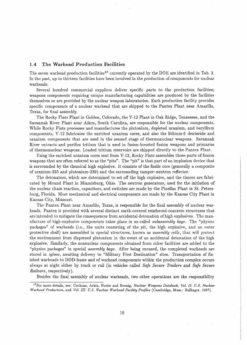
1.4 The Warhead Production Facilities
The seven warhead production facilities13 currently operated by the DOE are identified in Tab. 3.In the past, up to thirteen facilities have been involved in the production of components for nuclearwarheads.
Several hundred commercial suppliers deliver specific parts to the production facilities;weapons components requiring unique manufacturing capabilities are produced by the facilitiesthemselves or are provided by the nuclear weapon laboratories. Each production facility providesspecific components of a nuclear warhead that are shipped to the Pantex Plant near Amarillo,Texas, for final assembly.
The Rocky Flats Plant in Golden, Colorado, the Y-12 Plant in Oak Ridge, Tennessee, and theSavannah River Plant near Aiken, South Carolina, are responsible· for the nuclear components.While Rocky Flats processes and manufactures the plutonium, depleted uranium, and berylliumcomponents, Y-12 fabricates the enriched uranium ceres, and also the lithium'"6 deuteride anduranium components that are used in the second stage of thermonuclear weapons. SavannahRiver extracts and purifies tritium that is used in fusion-boosted fission weapons and primariesof thermonuclear weapons. Loaded tritium reservoirs are shipped directly to the Pantex Plant.
Using the enricheduranium cores sent from Y-12, Rocky Flats assembles those parts offissionweapons that are often referred to as the "pits". The "pit" is that part of an implosion device thatis surrounded by the chemical high explosive. It consists of the fissile core (generally a compositeof uranium-235 and plutonium-239) and the surrounding tamper-neutron reflector.
The detonators, which are determined to set off the high explosive, and the timersare fabricated by Mound Plant in Miamisburg, Ohio. The neutron generators, used for the initiation ofthe nuclear chain reaction, capacitors, and switches are made by the Pinellas Plant in St. Petersburg, Florida. Most mechanical and electrical components are made by the Kansas City Plant inKansas City, Missouri.
The Pantex Plant near Amarillo, Texas, is responsible for the final assembly of nuclear warheads. Pantex is provided with several distinct earth-covered reinforced-concrete structures thatare intended to mitigate the consequences from accidental detonation ofhigh explosives. The manufacture of high-explosive components takes pIace in so-called subassembly bays. The "physicspackages" of warheads (Le., the units consisting of the pit, the high explosive, and an outerprotective shell) are assembled in special structures, known as assembly cells, that wiU protectthe environment from dispersed plutonium in the event of an accidental detonation of the highexplosive. Similarly, the nonnuclear components obtained from other facilities are added to the"physics packages" in special assembly bays. After being encased, the completed warheads arestored in igloos, awaiting delivery to "Military First Destination" sites. Transportation of finished warheads to DOD-bases and of warhead components within the production complex occursalways at night eitherby truck or raH (in vehiclescalled Safe Secure Trailers and Safe SecureRailcars, respectively).
Besides the final assembly of nuclear warheads, two other operations are the responsibility
13For more details, see: Cochran, Arkin, Norris and Hoenig, Nuclear Weapons Databook, Vol. 11: U.S. NuclearWarhead Production, and Vol. II1: U.S. Nuclear Warhead Facility Profiles (Cambridge, Mass.: Ballinger, 1987).
10
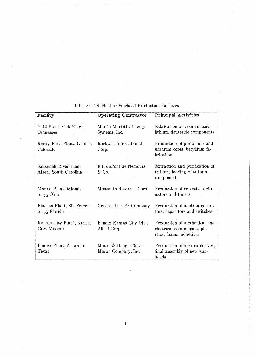
Table 3: U.S. Nuclear Warhead Production Facilities
Facility
Y-12 Plant, Oak Ridge,Tennessee
Rocky Flats Plant, Golden,Colorado
Savannah River Plant,Aiken, South Carolina
Mound Plant, Miamisburg,Ohio
Pinellas Plant, St. Petersburg, Florida
Kansas City Plant, KansasCity, Missouri
Pantex Plant, Amarillo,Texas
Operating Contractor
Martin Marietta EnergySystems, Inc.
Rockwell InternationalCorp.
E.L duPont de Nemours& Co.
Monsanto Research Corp.
General Electric Company
Bendix Kansas City Div.,Allied Corp.
Mason& Hanger-SilasMason Company, Inc.
11
Principal Activities
Fabrication of uranium andlithium deuteride components
Production of plutonium anduranium cores, beryllium fabrication
Extraction andpurification oftritium, loading oftritiumcomponents
Production of explosive detonators and timers
Production of neutron generators, capacitors and switches
Production of mecha..Tlical andelectrical components, plastics, foams, adhesives
Production of high explosives,final assembly of new warheads
of the Pantex Plant, an of them going on simultaneously, and each requiring almost equal time,space, and labor. The first is the maintenance, modification and reliability testing of stockpiledwarheads. The second operation is the complete disassembly of retired warheads withdrawn fromthe military stockpile.
2 U.S. Nuclear Warheads - Design and Development Program
2.1 Military Characteristics of Warheads
The fundamental research on the physics and technology of nuclear weapons done by the scientistsand engineers in the design laboratories in Los Alamos and Livermorevery often generate ideas fornew nuclear weapon concepts. If such a new concept looks promising, the laboratories offer theirideas to the Department of Defense (DOD). Although not all of these new concepts are actuallybrought into reality, the early research and development activity of the nuclear weapon design laboratories i8 the major source ofmore sophisticated as weIl as completely new nuclear weapon systems. Examples are fusion-boosted fission warheads, reduced-blastjenhanced-radiation weaponsand the nuclear-explosive powered X-ray laser, which is currently under investigation.
Another source of ideas for new nuclear weapons is a direct request by the military. Wheneverthe Department of Defense believes that there is a need for a new mission that might be accomplished by a new delivery system, the requirements for the delivery system are specified, andthe DOE-operated weapon design laboratories are asked to state how the requirements for thewarhead could be met. Those warhead requirements generaily affect the yield, size, and weight ofthe warhead, as weil as the position of its center of gravity and its ability to withstand shock andacceleration. Sometimes the requirements are met by modifying warheads from existing systems,hut in order to achieve maximum military effectiveness, more often than not, a new warheadisdesigned. The policy todesign a new warhead rather than to take an existing one issomewhatfacilitated by the fact, that the development and production of a warhead accounts for only 10to 15 percent of the total cost of the delivery system.14
The requirements for the nuclear warhead are defined by a DOD-prepared set of militarycharacteristics (MCs). As an example, the militarycharacteristics for the warhead for the MXmissile are:15
• Nuclear safety (e.g., no nuclear yield in an accident and positive measures toprevent inadvertent arming and firing).
• Size and weight of DOE-designed components to ensure compatibility with the specifiedreentry vehicle.
• Plutonium dispersal safety in case of an accident.
• Operational reliability.
14 Energy and Technology Review, Lawrence Livermore National Laboratory, September 1986, p. 2.15Ibid., p. 8.
12
• Yield.
• Conservative use of nuclear materials (e.g., enriched uranium, plutonium, tritium) to minimize cost.
• Minimum maintenance.
• .Operational simplidty.
According to a Livermore publication16 , "the DOD requires that, in the event that compliancewith these MCs leads to a design conflict, priorities shall be observed in the order listed above,giving consideration to tradeoffs that allow high-priority MCs to beattained while minimizingthe degradationof the competing, lower-priority MCs. Thefinal quantitative values for the MCsare often arrived at through an iterative processbetween the DOE and the DOD. The designlaboratories determine what js technically possible, and the DOn and the DOE then come tomutual agreement as to the appropriate tradeoffs to minimize the overall cost of the weaponsystem while maximizing the system's capabilities".
According to the same sourte, the DOE and DOD "have always been concerned about warheadendurance and replicability, but tradeoffs to achieve other weapon features have previously beenparamount" . Only in 1982, the Department of Defense added a paragraph concerning warheadendurance and replicability to the military characteristics in which these two features aredescribedto be desirable goals consistent with meeting the othermilitary characteristics. For the MXwarhead,this paragraph states:
"It is desired that the warheads have an inherent endurance obtained as a result of design considerations that address: a maximum warhead lifetime, maximizing the abilityto replicate the warhead at a future date, and maximizing the ability to incorporatethis warhead in other weapon delivery systems. Therefore, the design, development,and production of the warhead must be weIl documented and involve processes at afuture date."17
2.2 The Life Cycle of Warheads
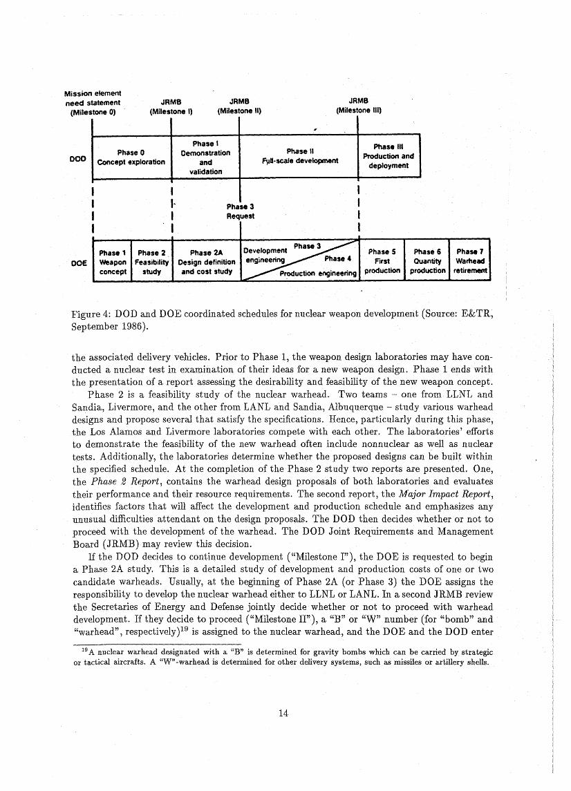
The complete warhead development cycle is divided into seven (or eight) distinct phases18 (Fig. 4).In Phase 1, the weapon concept study, the nOE and DOD jointly establish astudy group that ischaired by an officer from the responsible military service (Arrny, Air Force, Navy). Representatives from the weapon design laboratoriesdirectly support thestudy group, which considers thegeneralweapon-system architecture required to fulfill a spedfied military role. During this phase,which takes about one year, the values for the warhead parameters, such as yield, size, weightand spedfic safety and security features are defined along with the weapon system's mission and
16Ibid., p. 8.17Ibid., p. 8.18Ibid., pp. 19-25.
13
Mission elementneed statement
(Milestone 0)JRMB
(Milestone I)JRMB
(Mitestone 11)JRMB
(MiJestone 111)
000
.,
Phase I Phase UIPhase 0 Demonstration Phase 11
Production andConcept exploration and f1a1l-scale development
deploymentvalidation
I I IPhase 3Request
aOEPhase 1 Phase 2weapon Feasibilityconcept study
Phase 2ADesign definitionand cost study
Phase 3Oevelopment Phase 5engineering Phase 4 First
p~uction engineering production
Phase 6 Phase 1Quantity Wamead
production retirement
Figure 4: DOD and DOE coordinated schedules for nuc1ear weapon development (Source: E&TR,September 1986).
the associated delivery vehic1es. Prior to Phase 1, the weapon design laboratories may have conducted a nuclear test in examination of their ideas for a new weapon design. Phase 1 ends withthe presentation of areport assessing the desirability and feasibility of the new weapon concept.
Phase 2 is a feasibility study of the nuc1ear warhead. Two teams - one fromLLNL andSandia, Livermore, and the other from LANL and Sandia, Albuquerque - study various warheaddesigns andpropose several that satisfy the specifications. Hence, particularly during this phase,the Los Alamos and Liverrnore laboratories compete with each other. The laboratories' effortsto demonstrate the feasibility of the new warhead often include nonnuclear as weil as nucleartests. Additionaily, the laboratories determine whether the proposed designs can be built withinthe specified schedule. At the completion of the Phase 2 study two reports are presented. One,the Phase 2 Report, contains the warhead design proposals of both laboratories and evaluatestheir performance and their resource requirements. The second report, the Major Impact Report,identifies factors that will affect the development and production schedule and emphasizes anyunusual difficulties attendant on the design proposals. The DOD then decides whetheror not toproceed with the development of thewarhead. The DOD Joint Requirements and ManagementBoard (JRMB)· may review this decision.
If the DOD decides to continue development ("Milestone I"), the DOE is requested to hegina Phase 2A study. This is a detailed study of development and production costs of one or twocandidate warheads. Usually, at the heginning of Phase 2A (or Phase 3) the DOE assigns theresponsihility to develop the nuc1ear warhead either to LLNL or LANL. In a second JRMB reviewthe Secretaries of Energy and Defense jointly decide whether or not to proceed with warheaddevelopment. If they decide to proceed ("Mile8tone II"), a "B" or "W" number (for "bomb" and"warhead", respectively)19 i8 assigned to the nuc1ear warhead, and the DOE and the DOD enter
I9A nuclear warhead designated with a "B" is determined for gravity bombs which ean be earried by strategieor tactical aircrafts. A "W"-warhead is determined for other delivery systems, such as missiles or artillery shells.
14
into a contract, called the Military Characteristics Document, that specifies the delivery systemand yield, size, weight, reliability, stockpile lifetime, and safety and security characteristics of thewarhead. A second document describes the logistical and operational concepts for the warheadand spedfies the normal and abnormal environments that the warhead must withstand (e.g.,temperature, acceleration, vibration, shock, incident radiation).
The full-scale development engineering program begins with Phase 3. During this phase,numerous engineering tests and a few underground nuelear tests are carried out. These tests are"intended to demonstrate that the warhead will meet performance and safety requirements andspecifications for safeguarding the environment" .20 As a result of these tests, the warhead designmay be slightly altered.
In Phase 4, the DOE production plants begin preproduction engineering activities in accordance with the information transmitted by the design laboratory. During this phase, the designlaboratory continues to conduct engineering tests and a nuelear test of the warhead in its fullyweaponized configuration may take place (final proof test). The testing program during Phases 3and 4 is "designed to prove that a weapon can
• function compatibly with its delivery system,
• survive its specified operational environments,
• remain safely in the stockpile formany years without significant deterioration,
• be used during battle by military personnei,
• behave predictably and safely in extreme and abnormal environments."21
In Phase 5, the first actualstockpile unit is produced. If final checks are positive, the weapondesign laboratory certifies that the warhead functions properly. On the average, it takes about 8to 10 years from the beginning of Phase 1 to the end of Phase 5. Typically, 5 to 10 nuelear testsare required to develop theprototype of a new warhead.
Phase 6 begins when the first warheads are delivered to the Department of Defense andextendsthroughout the entire stockpile life of the warheads that is typically 20 to 30 years. During thistime, the DOE carries out a careful stockpile surveillance program. Warheads are routinelyselected at random from the stockpile and returned to the production plants at a rate of aboutone or two units per warhead type and year. After disassembly of a warhead, its componentsare sent to the facilities where they were originally assembled. For a careful inspection of thewarhead components someparts have to be machined apart, because they are brazed, welded orglued together. Hence, a warhead that was subject to such an inspection, cannot be rebuilt ortested in an underground nuelear test in its original configuration.
The stockpile surveillance program ineludes a variety of nondestructive checks of the warhead components, such as optical inspection, mechanical tests, and tests of the electrical system.Sometimes the fissile materials are replaced by inert material and the high explosive is detonated
20 Energy and Technology Review, ap. cit., p. 24.21Ibid., p. 25.
15
to see whether the implosion device works as desired. If the test program reveals any deterioration of some component (e.g.) corrosion, decomposition of plastic materials, increased friction ofmechanical components), additional warheads may be inspected to provide a basis for deeision,whether the defect isa one-unit anomaly or a problem that might affect all stockpiled warheadsof this type.
After a stockpile life of typically 15 to 25 years, the warheads are retired in Phase 7. Thewarheads are returned from stockpile to the production plants and disassembled. The nuclearmaterials, such as enriched uranium, plutonium and tritium, are recyc1ed, and eventually used innew warheadsj the remainder is discarded.
3 N uclear Testing
3.1 Nuclear Test/ Sites
Since the invention of nuclear weapons, six countries are known to have conducted test explosionsof nuclear devices: the United States of America, the Sovie±'Union, the UnitedKingdom, Prance,the People's Republic of China, and India. Although Israel reportedly possesses nuclear weapons,it is not known to have carried out any nuclear test explosion.
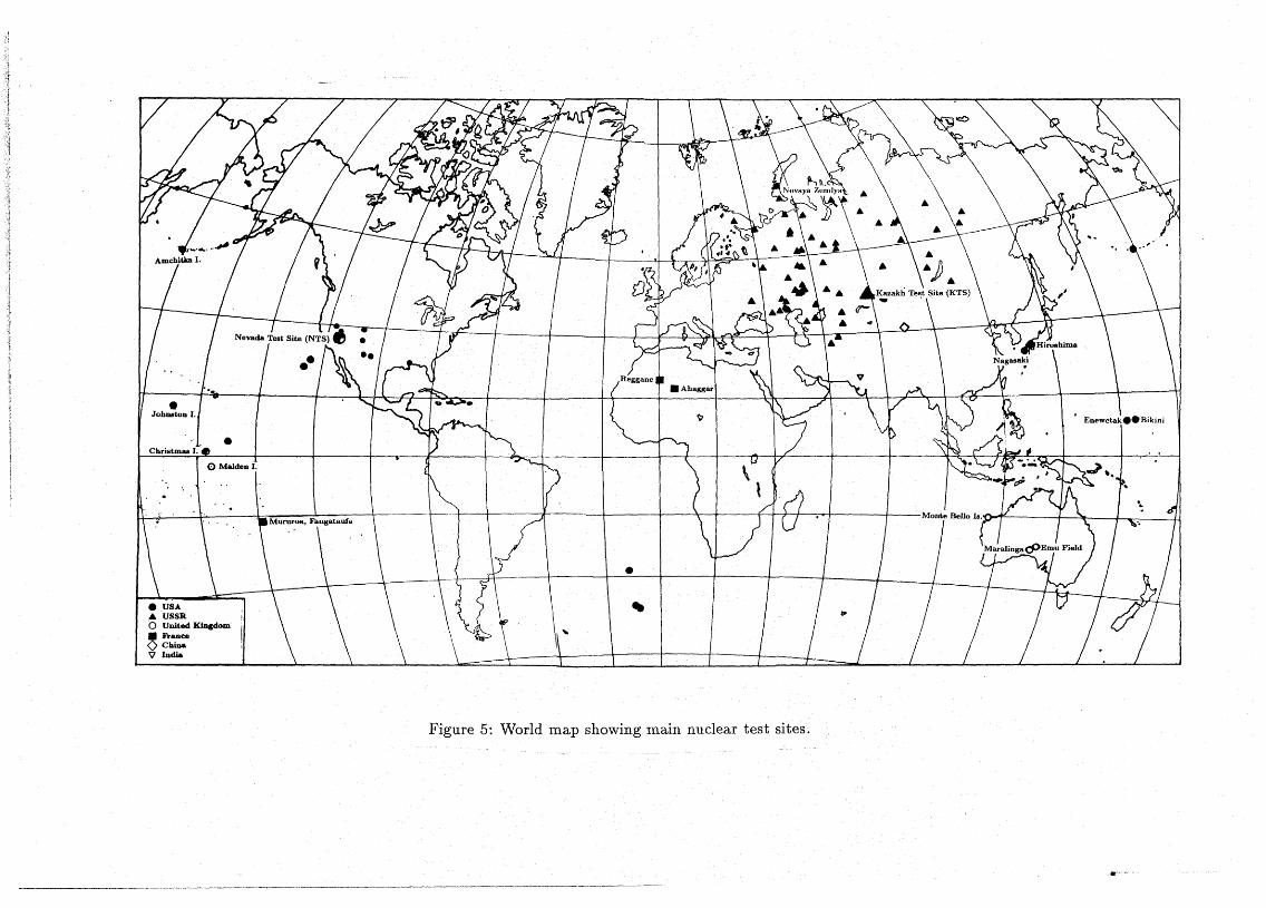
Nuclear explosions have occurred almost all over theworld: in all continents (except Antarctica) as weIl as in the Paeific and in the South Atlantic (see Fig. 5. Only the Soviet Union, China,and India conClucted all their nuclear tests within their state boundaries. The United Kingdomand France, on the other hand, never carried out a nuclearexplosion on their Q~n territory.
3.1.1 United States
Theworld's first nuclear device was detonated by the United States on 16July 1945. A portionofthe Alamogordo Bombing Range in the-Jornada deI Muerto (Journey ofDeath), west of Carrizozo,New Mexico, was chosen as the site for this test after evaluating eight possible areas in the westernUnited States.22 The testdevice, code-named Trinity, was mounted on a tower 30.5 meters abovethe desert floor. Upon firing, it far surpassed the by then biggest man-made explosion, releasingan energy equivalent to the detonation of 21,000 tons of TNT.
The next two nuclear devices buHt by the United States were dropped on the Japanese eitiesof Hiroshima and Nagasaki in August 1945, causing ahout 300,000 casualties. These bombs are- and hopefully will remain - the only nuclear weapons ever used in combat.
Testing in the Pacific At the end of 1945, the USA began a search for a nuclear test site wherethe planned experiments to test nuclear weapon effects and new designs could be conducted.
22The other seven loeations that had been eonsidered are: the Tularosa Basin in New Mexico; a desett area nearRiee, California; San Nieholas Island off Southern California; the lava region south of Grants, New Mexieo; an areasouthwest of Cuba, New Mexico; sand bars off the eoast of South Texas; and the San Luis Valley region near theGreatSand Dunes National Monument in Colorado (Los Alamos; The Beginning 01 an Em, LASL-79-78 Reprint,Los Alamos National Laboratory, May 1984, p. 32).
16
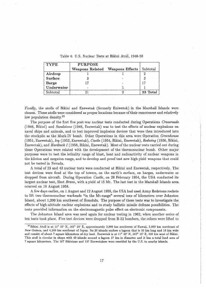
Table 4: U.S. Nuclear Tests at Bikini Atoll, 1946-58
TYPE PURPOSEWeapons Related Weapons Effects Subtotal
Airdrop 1 1 2Surface 3 - 3Barge 17 - 17Underwater - 1 1Subtotal 21 2 23 Total
Finally, the atolls of Bikini and Enewetak(formerly Eniwetok) in the MarshaU Islands werechosen. These atolls were consider.ed as proper locations·because oftheirremoteness and relativelylow population density.23
The purpose of the first five post-war nuclear tests conducted during Operations Grossroads(1946, Bikini) and Sandstone (1948, Enewetak) was to test the effects of nuclear explosions onnaval ships and animals, and to test improved implosion devices that werethen introduced intothe stockpile as the Mark-IV bomb. Other Operations in this area were Operation Greenhouse(1951, Enewetak), Ivy (1952, Enewetak), Castle (1954, Bikini, Enewetak), Redwing (1956, Bikini,Enewetak), and Hardtack I (1958, Bikini, Enewetak). Most ofthe nuc1ear tests carried out duringthese Operations were related with the development of the thermonuclear bomb. Other majorpurposes were to test the lethality range of blast, heat and radioactivity of nuc1ear weapons inthe kiloton and megaton range, and to develop and proof test new high-yield weapons that couldnot be tested in Nevada.
A total of 23 and 43 nuclear tests were conducted at Bikini and Enewetak, respectively. Thetest deviees were fired at the top of towers, on the earth's surface, on barges, underwater ordropped from aircraft. During Operation Castle, on 28 February 1954, the USA conducted Hslargest nuclear test, Shot Bravo, with a yield of 15 Mt. Thelast test in the Marshall Islands areaocurred on 18 August 1958.
A few days earlier, on 1 August and 12 August 1958, the USA had used Army Redstone rocketsto lift two thermonuclear warheads "in the Mt-range"several tens of kilometers over JohnstonIsland, about 1,200 km southwest of Honolulu. The purpose of these tests was to investigate theeffects of high-altitude nuc1ear explosions and to study ballistic missile defense possibilities. Thetests provided information on the electromagnetic pulse effect on electronic components.
The Johnston Island area was used again for nuclear testing in 1962, when another series often tests took place. Five test devices weredropped from B-52 bombers, the others were lifted to
23Bikini Atoll is at 110 35' N, 165 0 23' E, approximately 3,900 km southwest of Hawaü, 3,000 km northeast ofNew Guinea, and 4,200 km southeast of Japan. Its20 islands enclose a lagoon that is 35 km long and 18 km wideand consist of about 7 square kilometers of dry land. Enewetak is at 11 0 30' N, 1620 15' E, 330 km west of Bikini.This atoll is circular in shape with 40 islands around a lagoon 37 km in diameter and it has a total land area of7 square kilometers. The 167 Bikinians and 137 Enewetakese were resettled by the D.S. to nearby islands.
17
•Christmaa J.
<:> MaIden J.
•.&o United KiDgdom• hanceo ChiDa'V India
Figure 5: World map showing main nuclear test sites;
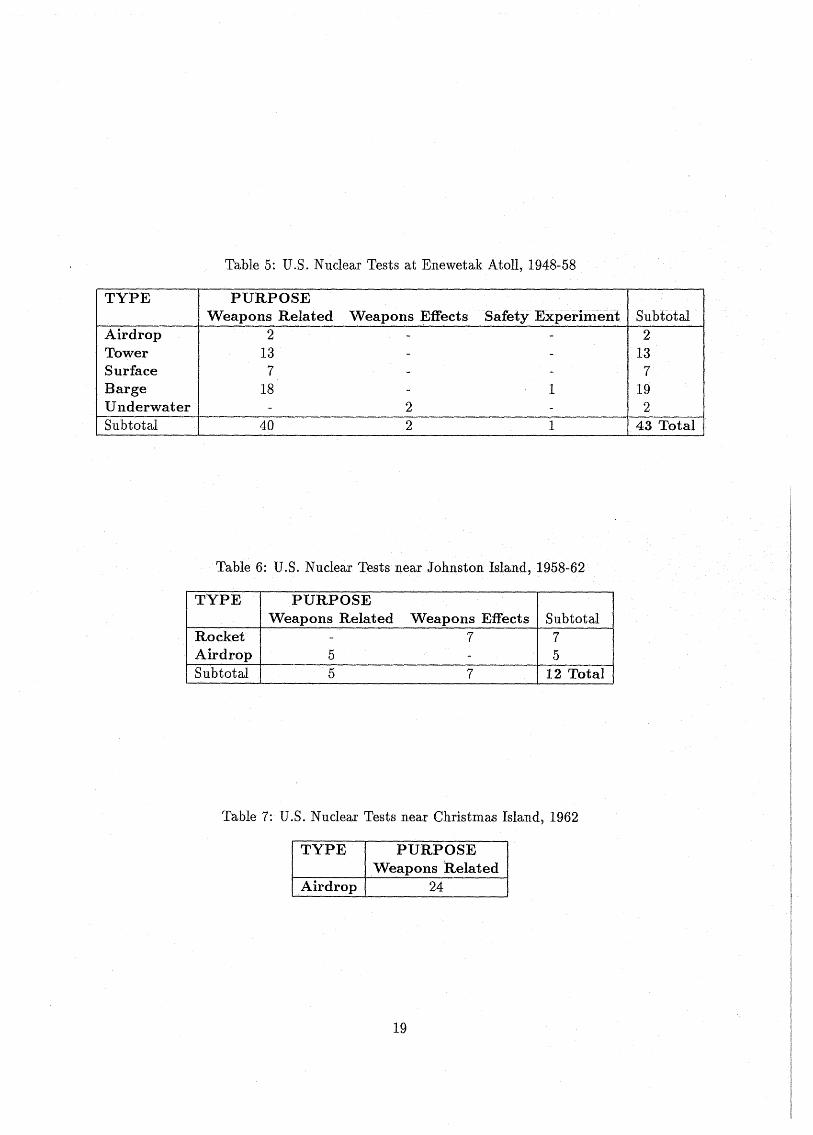
Table 5: U.S. Nuc1ear Tests at Enewetak Atoll, 1948-58
TYPE
AirrlropTowerSurfaceBargeUnderwaterSubtotal
PURPOSEWeapons Related
2137
18
40
Weapons Effects
22
Safety Experiment Subtütal2
137
1 192
1 43 Total
Table 6: U.S. Nuclear Tests near Johnston Island, 1958-62
TYPE PURPOSEWeapons Related Weapons Effects Subtotal
Rocket - 7 7Airrlrop 5 - 5Subtotal 5 7 12 Total
Table 7: U.S. Nuclear Tests near Christmas Island, 1962
TYPE PURPOSEWeapons Related
Airdrop 24
19
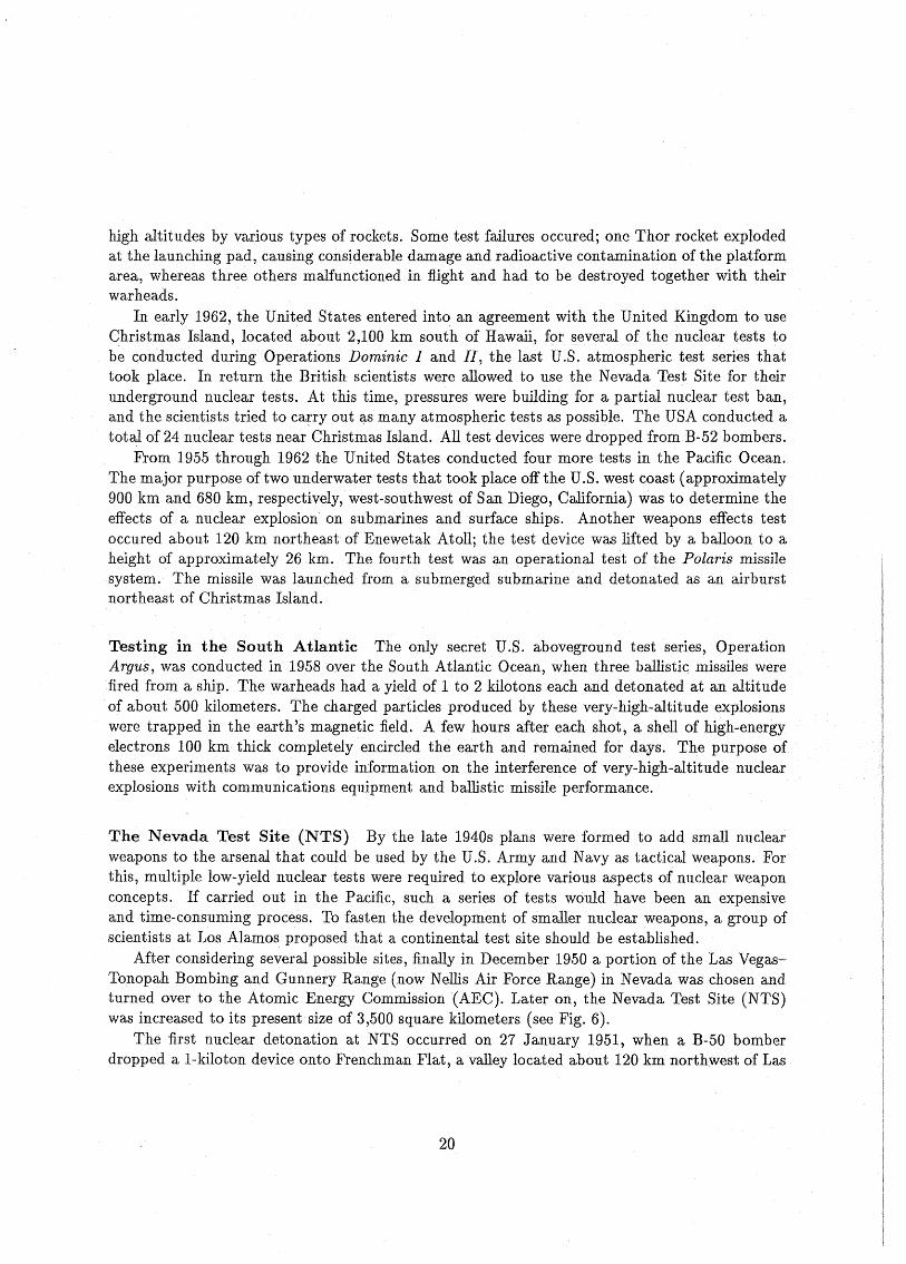
high altitudes by various types of rockets. Some test failures occured; one Thor rocket explodedat the launching pad, causing considerable damage and radioactive contamination of the platformarea, whereas three others malfunctioned in fiight and had to be destroyed together with theirwarheads.
In early 1962, the United States entered into an agreement with the United Kingdom to useChristmas Island, located about 2,100 km south of Hawaii, for several of the nuclear tests tobe conducted during Operations Dominic land 11, the last U.S. atmospheric test series thattook place. In return the British scientists were allowed to usethe Nevada Test Site for theirunderground nuclear tests. At this time, pressures were building for a partial nuclear test ban,and the scientists tried to carry out ~s many atmospheric tests as possible. The USA conducted atotal of 24 nuclear tests near Christmas Island. All test devices were dropped fromB-52 bombers.
From 1955 through 1962 the United States conducted four more tests in the Pacific Ocean.The major purpose of two underwater tests that took place off the U.S. west coast (approximately900 km and 680 km, respectively, west-southwest of San Diego, California) was to determine theeffects of a nuclear explosion on submarines and surface ships. Another weapons effects testoccured about 120 km northeast of Enewetak Atoll; the test device was lifted by a balloon to aheight of approximately 26 km. The fourth test was an operational test of the Polaris missilesystem. The missile was launched from a submerged submarine and detonated as an airburstnortheast of Christmas Island.
Testing in the South Atlantic The only secret U.S. aboveground test series, OperationArgus, was conducted in 1958 over the South Atlantic ücean, when three bailistic missiles werefired from a ship. The warheads had a yield of 1 to 2 kilotons each and detonated at an altitude
·of about 500 kilometers. The charged particles produced by these very-high-altitude explosionswere trapped in the earth's magnetic field. A few honrs after each shot, a shell of high-energyelectrons 100 km thick completely encircled the earth and remained for days. The purposeofthese experiments was to provide information on the interference of very-high-altitude nuclearexplosions with communications equipment and ballistic missile performance.
The Nevada Test Site (NTS) By the late 1940s plans were formed to add small nuclearweapons to the arsenal that could be used by the U.S. Army and Navy as tactical weapons. Forthis, multiple low-yield nuclear tests were required to explore various aspects of nuclear weaponconcepts. If carried out in the Pacific, such aseries of tests would have been an expensiveand time-consuming process. To fasten thedevelopment of smaller nuclear weapons, a group ofscientists at Los Alamos proposed that a continental test site should be established.
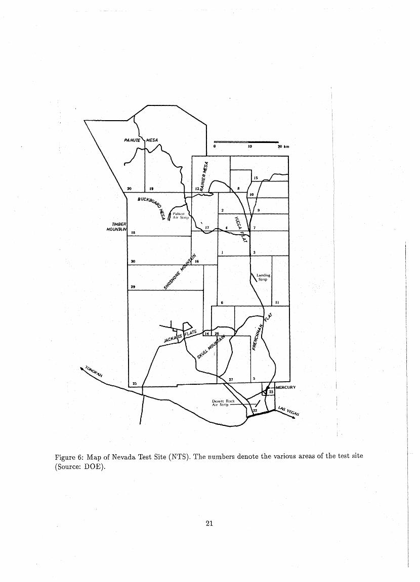
After considering several possible sites, finally in December 1950 a portion of theLas VegasTonopah Bombing and Gunnery Range (now Neilis Air Force Range) in Nevada was chosen andturned over to the Atomic Energy Commission (AEC). Later on, the NevadaTest Site (NTS)was increased to its present size of 3,500 square kilometers (see Fig. 6).
The first nuclear detonation at NTS occurred on 27 January 1951, when aB-50 bomberdropped a 1-kiloton device onto Frenchman Flat,a valley located about 120 km northwest of Las
20
TII~8ER
MOUNTAIN18
30
o 10
3
20 km
Figure 6: Map of Nevada Test Site (NTS). The numbers denote the various areas of the test site(Source: DOE).
21
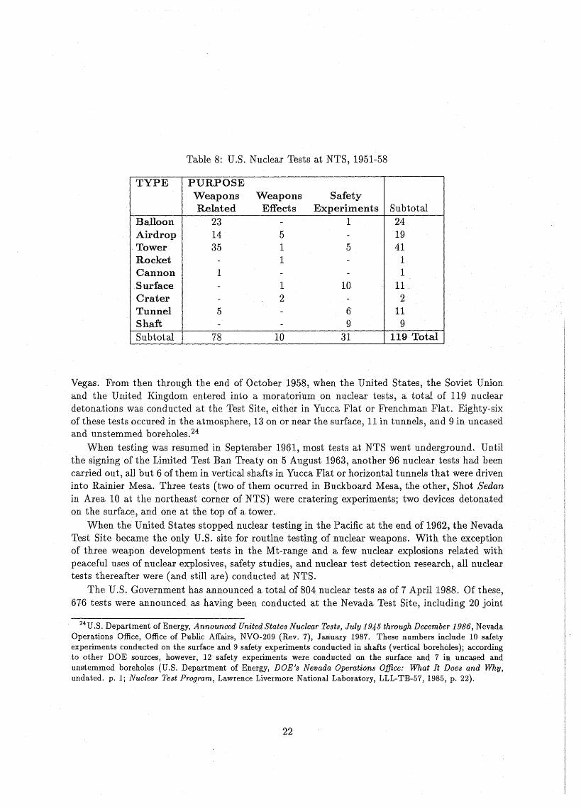
Table 8: U.S. Nuclear Tests at NTS, 1951-58
TYPE PURPOSEWeapons Weapons SafetyRelated Effects Experiments Subtotal
Balloon 23 - 1 24Airdrop 14 5 - 19Tower 35 1 5 41Rocket - 1 - 1Cannon 1 - - 1Surface - 1 10 11Crater - 2 - 2Tunnel 5 - 6 11Shaft - - 9 9Subtotal 78 10 31 119 Total
Vegas. From then through the end of October 1958, when the United States,the Soviet Unionand the United Kingdom entered into a moratorium on nucleartests, a total of 119 nucleardetonations was conducted at the Test Site, either in Yucca Flat or Frenchman Flat. Eighty-sixof these tests occured in the atmosphere, 13 on or near the surface, 11 in tunnels, and 9 in uncasea.and unstemmed boreholes. 24
When testing was resumed in September 1961, most tests at NTS went underground. Untilthe signing of the Limited Test Ban Treaty on 5 August 1963, another 96 nuclear tests had beencarried out, an but 6 ofthem in vertical shafts in Yucca Flat or horizontal tunnels that were driveninto RainierMesa. Three tests (two of them ocurred in Buckboard Mesa, the other, Shot Sedanin Area 10 at the northeast corner of NTS) were cratering experiments; two devices detonatedon the surface, and one at the top of a tower.
When the United States stopped nuclear testing in the Pacific at the end of 1962, the NevadaTest Site became the only U.S. site for routine testing of nuclear weapons. With theexceptionof three weapon development tests in the Mt-range and a few nuclear explosions related withpeaceful uses of nuclear explosives, safety studies, and nuclear test detection research, all nucleartests thereafter were (and still are) conducted atNTS.
The U.S. Government has announced a total of 804 nuclear tests as of 7 April 1988. Ofthese,676 tests were announced as having been conducted at the Nevada Test Site, including 20 joint
24U.S. Department of Energy, Announced United States Nuclear Tests, July 1945 through December 1986, NevadaOperations Office, Office of Public Affairs, NVO-209 (Rev. 7), January 1987. These numbers include 10 safetyexperiments conducted on the surface and 9 safety experiments conducted in shafts (vertical boreholes)j accordingto other DOE sourees, however, 12 safety experiments were conducted on the surface and 7 in uncased andunstemmed boreholes(U.S. Department of Energy, DOE's Nevada Operations Office: What It Does and Why,undated. p.l; Nuclear Test Program, Lawrence Livermore National Laboratory, LLL-TB-57, 1985, p. 22).
22
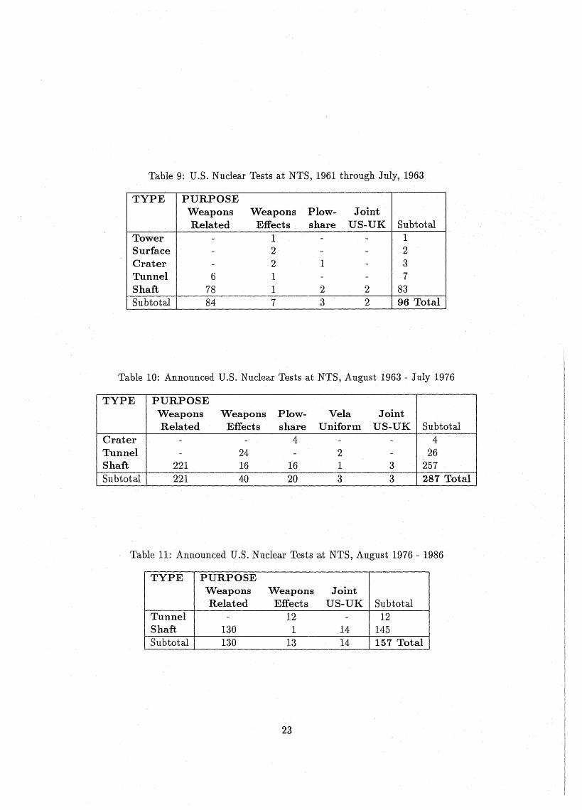
Table 9: U.S. Nuclear Tests at NTS, 1961 through July, 1963
TYPE PURPOSEWeapons Weapons Plow- JointRelated Effects share US-UK Subtotal
Tower - 1 - - 1Surface - 2 - - 2Crater - 2 1 - 3Tunnel 6 1 - - 7Shaft 78 1 2 2 83Subtotal 84 7 3 2 96 Total
Table 10: Announced U.S. Nuclear Tests at NTS, August 1963 - July 1976
TYPE PURPOSEWeapons Weapons Plow- Vela JointRelated Effects share Uniform US-UK Subtotal
Crater - - 4 - - 4Tunnel - 24 - 2 - 26Shaft 221 16 16 1 3 257Subtotal 221 40 20 3 3 287 Tota.l
Table 11: Announced U.S. Nuclear Tests at NTS, August 1976 - 1986
TYPE PURPOSEWeapons Weapons JointRelated Effects US-UK Subtotal
Tunnel - 12 - 12Shaft 130 1 14 145Subtotal 130 13 14 157 Total
23
U.S.-United Kingdom tests. The vast majority of these tests were related with the developmentof new nuclear weapon designs. The other tests were conducted to determine the effects of nuclearexplosions, tG> enhance the safety of nuclear weapons, to examine the useof nuclear explosivesforpeaceful purposes (Project Plowshare, canceled 1973), and to determine the seismic detectioncapability (Project Vela Uniform, canceled 1971).
Most weapons related tests now take place in vertical shafts in Yucca Flat or in PahuteMesa. The latter area is used for the higher-yield nuclear tests. Frenchman Flat is now usedfor experimental projects. The weapons effects tests that are carried outby the Defense NuclearAgency (DNA) take place in horizontal tunnels beneath Rainier Mesa.
The Nevada Test Site is administered by the Nevada Operations Office,25 located at LasVegas. This Office was created and resumed responsibility for operations and programs at theNevada Test Siteon 6 March 1962, when nuclear weapons testing became a year-round effort.The NTS previously had been operated for a few monthseach year by the Test Division ofthe Albuquerque Operations Office.26 The work of a few hundred scientists of LANL's TestOperations Office, LLNL's Nuclear Testing Office, and various divisions of both laboratories issupplemented by more than 8,000 contractor employees of the Nevada Operations Office workingat the NTS. The principal contractors are the Reynolds Electrical Engineering Company (REECo)for drilling and neId construction, EG&G Energy Measurements for technical support, Holmesand Narver (H&N) for construction architecture and engineering, and Fenix and Scisson (F&S)for drilling architecture and engineering.27
Other nuclear test locations in continental USA and Alaska As a result of the unabilityto testnew high-yield warheads outside the V.S. territory, the yields ofthe nuclear tests conductedat NTS increased in the early 1960s. On 13 September 1963, the 249-kiloton explosion Bilby inYucca Flat became the first underground test that was feIt in Las Vegas, causing considerablepublicconcern. In order to reduce ground shaking in Las Vegas, high-yield devices that followedBilby were then exploded beneath Pahute Mesa in the northwest corner of the Nevada Test Site.As plans were formed to test a new 1-Mt device, a somewhat more remote proving area near HotCreekValley, north of Warm Springs, was selected, called the Central Nevada Supplemental TestArea (CNSTA). This explosion, Shot Faultless on 19 January 1968, produced a fresh fault rupture
25The Nevada Operations Office is responsible for: management of all nuclear testing and associated aetivities atNTS, preparation of safety and effeets studies for each nuclear test before it iscondueted, management of researchprograms on the environmental effeets of manmade radiation, operation of the E-MAD facility at NTS that isbeing used in a research and demonstrationprogram for the handling and storage of highly radioaetive spentunreprocessed reaetor fuel, coordination of the Nuclear Emergency Search Team (NEST) that is responsible forlocating lost or stolen nuclear materials and handling technical problems associated with extortion threats involvingradiation dispersal or improvised nuclear devices (U.S. Department of Energy, DOE's Nevada Operations Office:What It Does and Why, undated. p. 4).
26U.S. Department of Energy, DOE's Nevada Operations Office: What It Does and Why, undated, p. 1.27B. Campbell, B. Diven, J. McDonald, B. Ogle and T. Scolman, "Field Testing - The Physical Proof of Design
Principles", Los Alamos Science, Vol. 4, No. 7 (Winter/Spring 1983), p. 164.
24
some 1,200 meters long in the desert floor in upper Hot Creek Valley.28 Five underground nucleartests with yields exceeding 1 Mt followed: Boxcar (4 April 1968), Benham (19 December 1968)and Handley (26 March 1970) were detonated beneath Pahute Mesa, whereas Milrow (2 October1969) and Cannikin (6 November 1971) were exploded on Amchitka, an island towards the westernend of the Aleutians, about 1,000 km from the Soviet coast. Cannikin was the proof test of theW71 warhead for the Spartan anti-ballistic missile (now retired); it is the largest undergroundnuclear test ever conducted by the United States (announced yield "less than 5 Mt").
Four out of the 27 nuclear tests conductedduring Project Plowshare occured outside theNevada Test Site. The first was Gnome,a 3-kiloton device that detonated in a saltbed nearCarlsbad, New Mexico, on 10 December 1961. The other three were prototype experiments to testthe effectiveness of nuclear explosions for large-scale gas stimulation. These tests were conductedin cooperation withthe private industry and the U.S. Department of Interior. While ShotsGasbuggy on 10 December 1967, near Farmington, New Mexico, and Rulison on 10 September1969, in Garfield County, Colorado, made use of single devices of 29 kilotons and 40 kilotons,respectively, three33-kiloton devices were simultaneously detonated in the Rio Blanco-experimenton 17 May 1973, near the town of Rifle in Rio Blanco County, Colorado.
As part of Project Vela Uniform, four nuclear underground detonations that were intended asseismicdetection experiments were carried out near Fallon, Nevada, near Hattiesburg, Mississippi,and on Amchitka Island. The 5.3-kiloton Salmon device was fired on 22 Gctober 1964, in theTatum Salt Dome nearHattiesburg. The cavity created by this explosion Was used two yearslater to decouple the 380-ton Sterling device.
Five plutonium-dispersal experiments with "zero" nuclear yield were conducted on the NellisAir Force Base Bombing Range in Nevada, adjacent to NTS. These experiments took place in1957 and 1963.
3.1.2 Soviet Union
Various locations have been reported for the first Soviet.nuclear weapon test on 29 August 1949:near Semipalatinsk at or near what is now known as the Kazakh Test Site (KTS), the UstyurtPlateau between the Caspian and Aral seas, and the northeast shore of the Caspian Sea.
The Soviet Union now maintains two nuclear weapon test sites, one southwest of Semipalatinskin eastern Kazakhstan (the KTS) and the other on Novaya Zemlya in the Arctic Ocean. Anumberof nuclear explosions were conducted outside these areas.
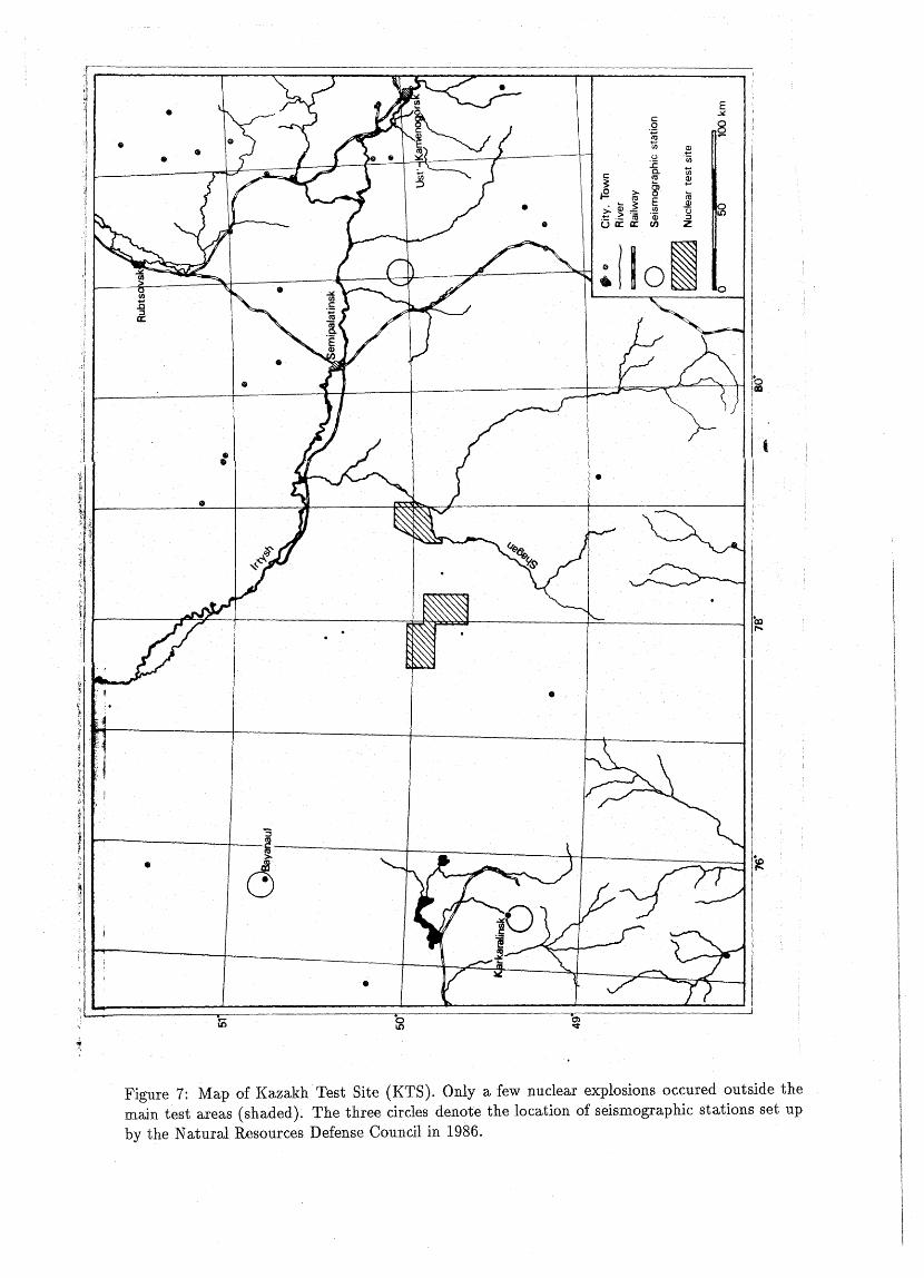
Testing at the Kazakh Test Site Most Soviet nuclear tests have been conducted at theKazakh Test Site (KTS)· in eastern Kazakhstan in an area of approximately 5,000 square kilometers. The eastern- and westernmost boundaries of this area are 100 and 200 kilometers, respectively, west-southwest of the city ofSemipalatinsk. A eloser look, however, reveals that KTSsplits in three distinct testing areas - Degelen Mountain, Shagan River, and Konyastan (see
28B. A. Bolt, Nuclear Explosions and Earthquakes - The Parted Veil (San Francisco: W. H. Freeman andCompany, 1976), p. 203.
25
Figure 7).29Atmospheric testing was done at KTS before 1963, but the exact locations of these tests are
not known. After the signing of the Partial Test Ban Treaty, underground tests were routinelyconducted at Degelen Mountain - probably in horizontal tunnels.
The first nuclear test in the Shagan River area took place on 15 January 1965; it was announcedby the Soviet Union as a peaceful nuclear explosion. The underground detonation of a 125-kilotondevice formed a crater with a diameter of approximately 400 meters; the crater lip was used toblock the Shagan River; the crater itself is now part of this artificial lake. Since the beginning ofthe 1970s, the Shagan River area is routinely used for underground testing in vertical shafts.
Tests conductedat Degelen Mountain and Konyastan are of low yield. Those tests exceeding20 or 30 kilotons are usually carried out at Shagan River or at Novaya Zemlya.
Testing on Novaya Zemlya The island of Novaya Zemlya in the Arctic Ocean is traditionallyused for the highest-yield nuclear explosions. Before 1963, more than80 nuclear explosions in themegaton-range took place in the air over Novaya Zemlya, including the largest weapon test everconducted, with a yield of 58 megatons. This island was then the main Soviet test site.
After 1963, the Soviet Union conducted underground nuc1ear tests with high yield at a sitejllst south of the Matochkin Shar Strait that divides Novaya Zemlya in two parts. Four tests tookplace at a second test site at the southwest end of Novaya Zemlya between 1973 and 1975.
The unfavourable climatic conditions do not allow the use of this site all the year round. Ofthe 33 underground nuclear tests that have been conducted at Novaya Zemlya through September1988, all but two occurred between August and October.
Testing in Western· Kazakhstan The Soviet Union detonated several nuclear devices inan area to the north of the Caspian Sea in western Kazakhstan that 1s known to contain thickunderground salt deposits and large salt domes.3D The salt deposits overlay a huge gas-condensatefield.31 Most tests occured on three distinct sites: one site is tO the north of Astrakhan, near themouth of the Volga river; the second is about 150 kilometers farther to the north, near Azgir, andthe third is the giant gas field near Orenburg.32 All tests conducted in these areas are believedto have served for peaceful purposes.
The first nuclear explosion conducted in the Orenburg gas-condensate field occurred on25 June 1970 near Tyul'gan. Two 15-kiloton explosions tookplace near Orenburg in 1971 and1973, respectively; one of these explosions reportedly produced a cavity with a volume of 50,000 m3
29The 720-meter-high Degelen Mountain is situated at 49 0 46' N and 78 0 02' E. The Shagan River area is atapproximately 50 0 N and 78 0 50' E; its southern and southeastern border is formed by the Shagan rlver and itsdammed waters. Konyastan is at about 49 0 55' N and 770 45' E.
30Lynn R. Sykes, Jack F. Evernden, and Ines Cifuentes, "Seismic Methods for Verifying Nuclear Test Bans",Physics, Techrwlogy, and the Nuclear Arms Race, American Institute of Physics Conference Proceedings No. 104,1983, pp. 85-133; here p. 114.
31 Iris Borg, "Nuclear Explosives - the Peaceful Side", New Scientist, 8 March 1984, pp. 10-13.32The Astrakhan area is at about 46 0 45' N and 48 0 15' E, whereas the Azgir area is at 470 50' N and 470 10' E;
the tests in the Orenburg gas field have been conducted in an area ranging from 51 0 20' N to 53 0 40' N, and from520 05' E to 55 0 40' E.
26
•
c"Q~(J)
~() "e;;1:
c Cl. tll'O
~~ 8'~ >- L.-
ctI El'O
• i ~ ~ ~(J) (.)> "15 "Q3 ::l• U ii a:: CI) z
•
•
•
•
:;
r------.,..4..--~--~--~Tl.-_=_--~~-------J. ~ ~
.11---~~---r-----vr--z:::::-~....------,--~"":':"':====~
~HI
,1
.1 I01 0
IIII • I
-q I/I • !i,
!i
iI'I ,I •,/ •
•
Figure 7: Map of Kazakh Test Site (KTS). Only a few nuclear explosions occured outside themain test areas (shaded). The three drcles denote the Ioeation of seismographie stations set upby the Natural Resources Defense Couneil in 1986.
at a depth of 1,140 meters.33 In 1972, two more explosions have been eondueted between Uralskand Buzuluk in an area that is rieh in oil shale. Two others oeeurred near Sterlitamak in 1972and 1973. Aseries of three explosions, in five-minute-intervals, took plaeenear Aksay on 10 July1983; a seeond series of three explosions at the same loeation followed on 21 July 1984.
Sinee 1980, a total of 13 nuclear explosions oeeured north of Astrakhan. It has been assumedthat these explosions were used toproduee large reservoirs in underground salt deposits to storegas eondensate before proeessing at nearby plants.34
3.1.3 United Kingdom
After the United Kingdom in 1947 had taken the decision to develop nuclear weapons, a sitehad to be determined for testing them. Britain initially sought to resume war-timeeollaborationwith the United States on nuclear matters by requesting the use of Enewetak atoll as a provingground. This would have enabled the British to use the equipment and infrastruetureof thisalready developed test site. The US, however, reacted distantly on this request and put off ananswer until September 1951. They then offered a joint test program at the Nevada Test Site, butnot without restrictions eoneerning the earrying out of the tests. Considering these restrictionsas unaeeeptable, Britain finally decided. in Deeemher 1951 to go her own way and to test hernuclear weapons in Australia.35
Prior to this decision, Britain had surveyed several sites around the world in order to findan appropriate Ioeation for her first nuclear test that should simulate a nuclear attaek on aharbour. A test site at the northeast coast of Seotland near Wiek was seriously eonsidered, butnot realized beeause of unfavourable weather eonditions.36 Another site, Groote Eylandt in theGulf oi Carpentaria in northern Australia, was also rejeeted for 'climatie reasons.37 A possiblesite in Canada, near Churehill, Manitoba, was ruled out, beeause the water was too shallow topermit ship operation near the shore.38 Finally, the ehoice fell on the Monte Bello Islands offAustralia's northwest coast, where the weather would allow a nuclear test in Oetober.39 In early1951, the British government formally requested perrnission from Australia to earry out a nucleartest in this area; the request was granted.40
Testing in A ustralia The first British nuclear deviee was detonated on board HMS Plymin the Monte Bello Islands on 3 Oetober 1952. Between 1953 and 1957 eleven more Britishatmospherie tests were earried out in Australla. Two of them took plaee in the Monte Bello
331. Borg, op. cit.; if this cavity is spherical, then its radius is approximately 23 meters.341. Borg, op. cit.35 Joan Smith, Glouds of Deceit: The Deadly Legacy of BritainJs Bomb Tests (Faber and Faber: London 1985),
pp. 32, 33; Department of Resources and Energy: A History of British Atomic Tests in Australia, prepared byJ. 1. Symonds (Australian Government Publishing Service:. Canberra1985), pp. 5-10.
36 "Regen rettete Schottland", Frankfurter Rundschau, 20 March 1985.37Department of Resources andEnergy, op. cit., p. 1l.38 Joan Smith, op. cit., p. 32.39Department of Resources and Energy, op. cit., pp. 7, 14.4°Ibid., pp. 6-8.
28
Islands, seven at Maralinga, and two at Emu Field. Maralinga and Emu Field were at that timealmost completely unexplored locations in a desert area of South Australia.41
In addition to the "major trials", Le. full-scale nuclear weapons tests, so-called "minor trials" (later renamed "Maralinga Experimental Programme") were also condueted. These wereessentially developmental experiments designed to examine the performance of various weaponcomponents, to studynew ideas, and to investigate how to increase the yield-to-weight ratio ofa weapon; furthermore, a few "safety tests" were carried out, which simulated the dispersal ofplutonium due to an accident with a nuclear weapon during transport and storage.42
One such test series involved initiator devices, code-named"Kittens" by the British, that wereto trigger. the chain reaction in the fissile material. Five such Kittens trials took place at EmuField in September and October 1953.43 Further Kittens trials were carried out at Maralingafrom 1955 through 1961.44
Two other test serieswere performed in order to study the compression and movement ofmaterials in an assembly under shock from detonated high explosive.45 Another test series wasdesigned to investigate how the nuclear materials reacted when an operational weapon is engulfedin fire. 46
Testing in the Pacific After Britain had gained enough experience in designing pure fissionand fusion-boosted fission devices, a program to test thermonuclear weapons was worked out.Since the yield of these weapons were tobe in the megaton range, testing took place in thePacific Ocean instead of in Australia. Three thermonuclear devices detonated near Malden Islandin 1957; other tests were carried out near Christmas Island in 1957 and 1958.
Testing in Nevada When pressures to cease nuclear testing in the atmosphere arose, GreatBritain entered into an agreement with the United States to use the Nevada Test Site for underground testing (see Section 3.1.1). The first joint U.S./U.K.-test took place at NTS on 1 March1962. Since then, all British nuclear tests are condueted underground at NTS.
3.1.4 France
France's decision to develop nuclear weapons dates back to the early 1950's. However, it was notuntil 1958 that the French governm~nt, led by General Charles de Gaulle, issued an official orderto manufacture and test the bomb.47
41The Maralinga Range is about 50 kilometers north of the Transcontinental Railway, between Watson andOoldea. Emu Field is 180 kilometers north-northwest of Maralinga.
42Department of Resoufces and Energy, op. cit., pp. 478, 479.43Ibid., pp. 157-162, 207.44Ibid., p. 479.45Ibid., p. 479.46Ibid., p. 479.47SIPRI Yearbook 1984 (Taylor & Francis: London, 1985), p. 52; Ulrich Delius, Tahiti - Fmnz"osisch-Polynesieri:
S"udseeparadies unter dem Atompilz (Gesellschaft f"ur bedrohte V"olker: G"ottingen, 1982), p. 40.
29
Testing in Algeria Like Britain, France has never conducted a nuc1ear test on its mainland.It started nuc1ear testing in the Sahara Desert in Algeria, which at that time belonged to France.The first French nuclear device was detonated on the top of a tower on 13 February 1960. Gf 17nuclear explosions known to have been conducted in Algeria until 1966, four took place in theatmosphere near Reggane, whereas 13 were carried out underground near Bordj-in-Eker in theAhaggar Mountains.
Testing in the Pacific When France gave independence to Algeria in 1962, it reserved theright to conduct nuclear tests in the Ahaggar Mountains for five more years. Although a numberof African states protested against the French testing activity in Algeria, it was the need fora suitable site to test the higher yield thermonuclear weapons rather than areaction to theinternational protests that led France to withdraw its testing facilities fromAlgeria and to turnto French Polynesia in the Pacific Ocean. There, at the southeast end ofthe Tuamotu Archipelago,France had set up its Pacific Nuclear Test Center (Centre d'Experimentation du Pacifique;CEP).
The main test site was built on the Mururoa atoll, a formerly uninhabited coral reef resting on-basaltic rock. Its islets enclose a lagoon that is 26 km lang and about 10 km wide. All technicalfacilities, including command posts and an airport, as weIl as housing areas are located at theeast end of the atoll. A subsidiary test site was buHt on Fangataufa, a small atollapproximately40 km southeast of Mururoa. A technical base for the assembly of nuc1ear devices i8 located atHao, an atoll about 500 km northwest of Mururoa.48
Concurrent with the beginning of nuclear testing in the South Pacific, France resumed testingin the atmosphere. The first test at Mururoa was carried out on 2 July 1966. From then throughthe end of 1974, a total of 41 nuclear devices havebeen detonated in the atmosphere; most of themwere mounted in containers lifted by balloons. Intensifying protests from several governments,environment protection organizations, and the general public forced France in 1972 to searchfor a suitable site for underground te8ting. Test drillings at Eiao, an island in the Marquesasisland group in north French Polynesia, and at Fangataufa revealed that the volcanic rocks areinadequate forunderground testing. Nevertheless, the first two underground tests were conductedat Fangataufa in 1975. Billce 1976, underground tests are carried out at Mururoa. Shafts aredrilled into the basaltic rock by drill rigs either on the smalliand surface or on ships inside thelagoon. Approximately 100 nuclear tests were conducted in this way.
In recent years, several accidents releasing radioactivity have been reported. The atoll isbelieved to be severely damaged and doubts are raised about its suitability for further nucleartesting. Obviously, France is considering to use Fangataufa again for underground testing.49
Prime Minister Michel Rocard announced on 27 August 1989 that France would reduce its annualrate of testing from eight to six in 1990.50
48Ulrich Delius, op. cit., p. 45.49 A classified report (probably prepared because of continued protests of Australia and New Zealand against
French testing in the Pacific) evaluating the geologieal· conditions in France suggests that there are areas thereappropriate for underground nuclear testing. Particularly mentioned are two sparsely populated locations nearQueret and Mageride in the Massif Central (SIPRI Yearbook 1985 (Taylor & Francis: London, 1985), p. 77.)
50 "Rocard Confirms Cuts In Pacific Nuclear Tests", International Herold Tribune, 28 August 1989.
30
3.1.5 China
All Chinese nuelear tests were and still are carried out in the Lop Nur area in southern Xinjiang.A survey for a suitable test site had begun in the summer of 1958.51 The Lop Nur NuelearWeapons Test Base was then formally established on 16 Oetober 1959.52 Aceording to pressreports,53 the test site has a size of more than 100,000 squar~ kilometers. Hs boundaries areformed by the mountain range ofthe Altun Shan in the south, the Tarim river-bedin the west,the foothillsof the Tian Shan and theTurpan dip inthe north, and the Gobi desert in the east.
China eondueted its first nuelear test on 16 Oetober 1964. A total oftwenty-two tests oeeurredin the atmosphere (China is not party to the 1963 Partial Test Ban Treaty). Most of these tests,if not all, took plaee in the desert basin between the j\.ltun Shan and Kuruktag ranges, just tothe east of the Lop Nur salt lake. Sinee 1980, an tests iLre eonducted underground in an area justnorth of the Kuruktag mountain range. However, facilities for tests in the atmosphere are stillmaintained at the test site.54
3.1.6 India
India detonated only one nuelear device; the explosion took place on 18 May 1974 near Pokaranin the Rajastan desert.55 Although it was labeled a "peaceful nuelear explosion", the test wasclearly a teehnieal and political demonstration that India has the capability to build nuelearweapons.
3.2 Types and Purposes of Nuclear Tests
In thepast, nuelear explosions have oeeured in spaee, in the atmosphere, on the earth's surfaee,underwater, and underground. Nuelear devices have been lifted with roekets, suspended fromballoons, dropped from airplanes, fired from a cannon, mounted atop towers, placed on or eloseto the earth's surface, burried underground, and plaeed on or suspended from barges. From thebeginning, nuelear tests have been condueted for two main purposes: to develop new weapondesigns and to determine the effects of nuclear explosions. A relatively minor portion (less than10 percent of an known U.S. nuclear tests) have been conducted for other purposes. Table 12lists the known U.S. nuclear tests by purpose."Known" means that the nuclear tests have beeneither announced by the United Statesor detected with seismic means and reported by variousseientific institutions.56
51 lohn Wilson Lewis and Xue Litai, China Builds the Bomb (Stanford University Press: Stanford, 1988), p. 175.52Ibid., p. 17753Karl Grobe, "Atomwaffentests unweit der Route Marco Polos" I Frankfurter Rundschau, 1 November 1984.54SIPRI Yearbook 1985, (Taylor & Francis: London, 1985), p. 79.55R. Chidambaram, S. K. Sikka, and S. C. Gupta: "Phenomenology of the Pokaran PNE experiment", Pramana,
Vol. 24, pp. 245-258 (1985).56 All nuclear tests before 5 August 1963, and from 14 June 1979 through 2 April 1982, were announced by the
U.S. DOE. Forty-three unannounced nuclear tests have been detected with seismic means (35 from 1965 through1979 and 8 {rom 1983 through 1984) (T. B. Cochran, R. S. Norris, W. M. Arkin and M. M. Hoenig, "UnannouncedU.S. Nuclear Weapons Tests, 1980-1984", Nuclear Weapons Databook - Working Papers, NWD 86-1, Washington,
31
The various test categories are defined by the U.S. DOE as following: 57
Weapons Related: A nuclear detonation conducted for the purpose of testing a nuclear deviceintended for a specific type of weapon system.
Weapons Effects: A nuclear test to evaluate the civil or military effects of a nuclear detonationon various targets, such as military hardware.
Safety Experiment : Experiment designed to 'Confirm a nuclear explosion will not occur in caseof an accidental detonation of the explosive associated with the device.
Plowshare: Application of nuclear explosives to develop peaceful uses forvatomic energy.
Vela Uniform: Department of Defense (DOD)program designed to improve the capabilitytodetect, identify, and locate underground nuclear explosions.
Storage-Transportation: Detonations of combinations of high explosives and nuclear materialsdesigned to study distribution of nuclear materials during accidents in several transportationand storage con:fi.gurations.
Joint U.S ....U.K.: A nuclear test conducted jointly by the United States and the United Kingdom under a cooperative agreement in effect between the two countries since 4 August1958.
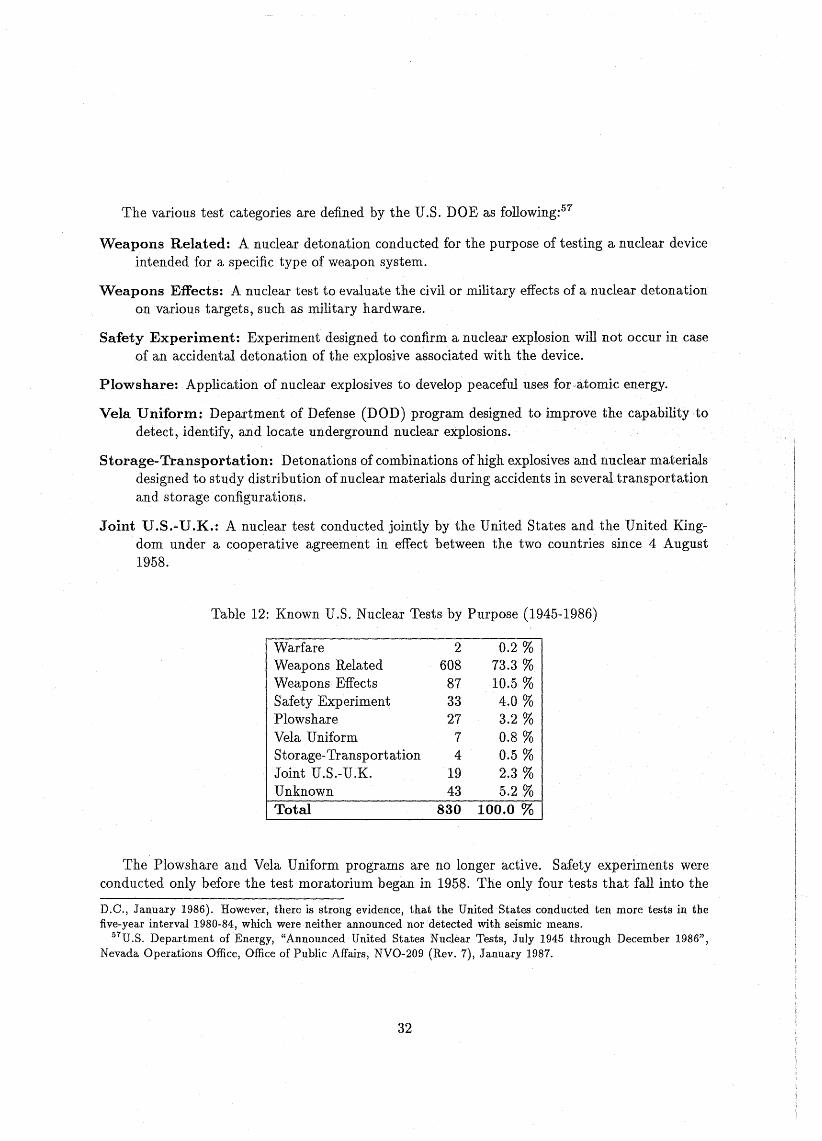
Table 12: Known U.S. NuclearTests by Purpose (1945-1986)
WarfareWeapons RelatedWeapons EffectsSafety ExperimentPlowshareVela UniformStorage-TransportationJoint U.S.-U.K.UnknownTotal
2608873327
74
1943
830
0.2 %73.3 %10.5 %4.0 %3.2 %0.8 %0.5 %2.3 %5.2 %
100.0 %
The Plowshare and Vela Uniform programs are no longer active. Safety experiments wereconducted only before the test moratorium began in 1958. The only four tests that fall into the
D.C., January 1986). However, there is strong evidence, that the United States conducted ten more tests in thefive-year interval 1980-84, which wereneither announced nor detected with seismic means.
57U .S. Department of Energy, "Announced United States Nuclear Tests, July 1945 through December 1986",Nevada Operations Office, Office of Public Affairs, NVO-209 (Rev. 7), January 1987.
32
category "Storage-Transportation" were conducted in 1963. Since the signing of the ThresholdTest Ban Treaty on 3 July 1974, more than 90 percent of ail U.S. nuclear tests were weaponsrelated.58
The term "weapons related" needs further elucidation. In most cases, the purpose of a nucleartest categorized as weapons related is to experimentaily verify certain design changes that havebeen made during the developmental process of a new warhead or bomb type. The test can alsobe intended to improve the knowledge of the basic physics of nuclear explosives or to explore newnuclear weapons concepts (such as "third-generation" nuclear weapons). The final proof tests ofnew weapons designs as weil as the confidence tests that are conducted to ensure the reliabilityof stockpiled nuclear weapons are alsodesignated as weapons related. Almost without exception,the actual purpose ofa nuclear test isnot publicly known.
Since 1963, when nuclear testing went underground due to the limitations set by the PartialTest Ban Treaty (PTBT), an weapons related tests are conducted in vertical shafts. The nucleardevice being tested is lowered to the bottom of a hole that was driiled to an appropriate depth,depending on the yield of the device (see the foilowing section). Each test requires a complexarrangement of diagnostic instruments to examine whether the device performs as desired. Properperformance is not alone determined,_by the yield of the nuclear explosive. Detailed measurementsinclude the recording of the neutron generation time via the emitted gamma rays, neutron fluencesin several energy ranges, and the absolute intensity, time, and energy distribution of weapongenerated x-rays. ApproXimately 15 announced weapons related nuclear tests take place at theNTS each yearjabout 10 percent of these are joint U.S.-U.K. tests.
At a rate of about two tests per year, the United States carry out weapons effects tests thatare determined to examine the effects of nuclear weapons on military hardware, communicationsystems, satellite materials, and so on. The DOD's Defense Nuclear Agency (DNA) is responsiblefor these tests.
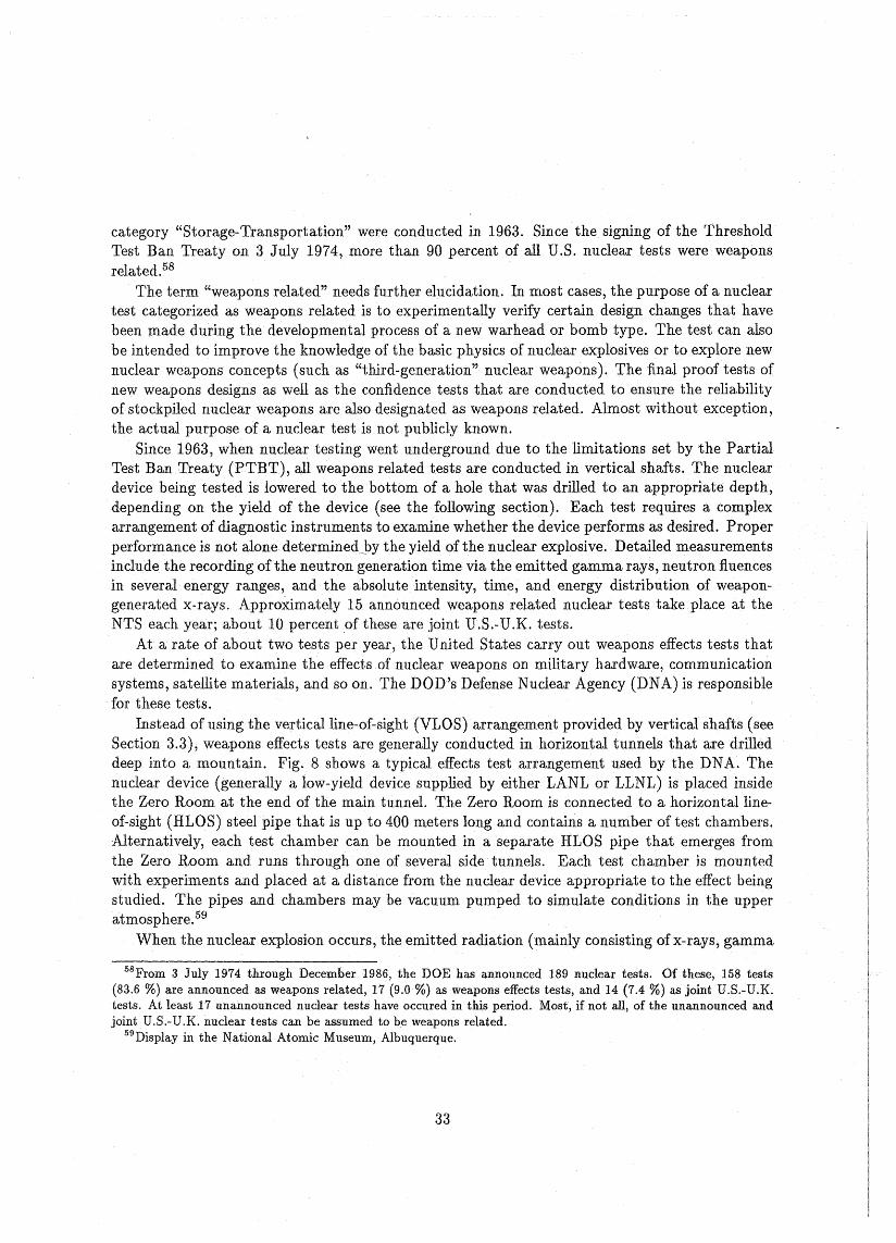
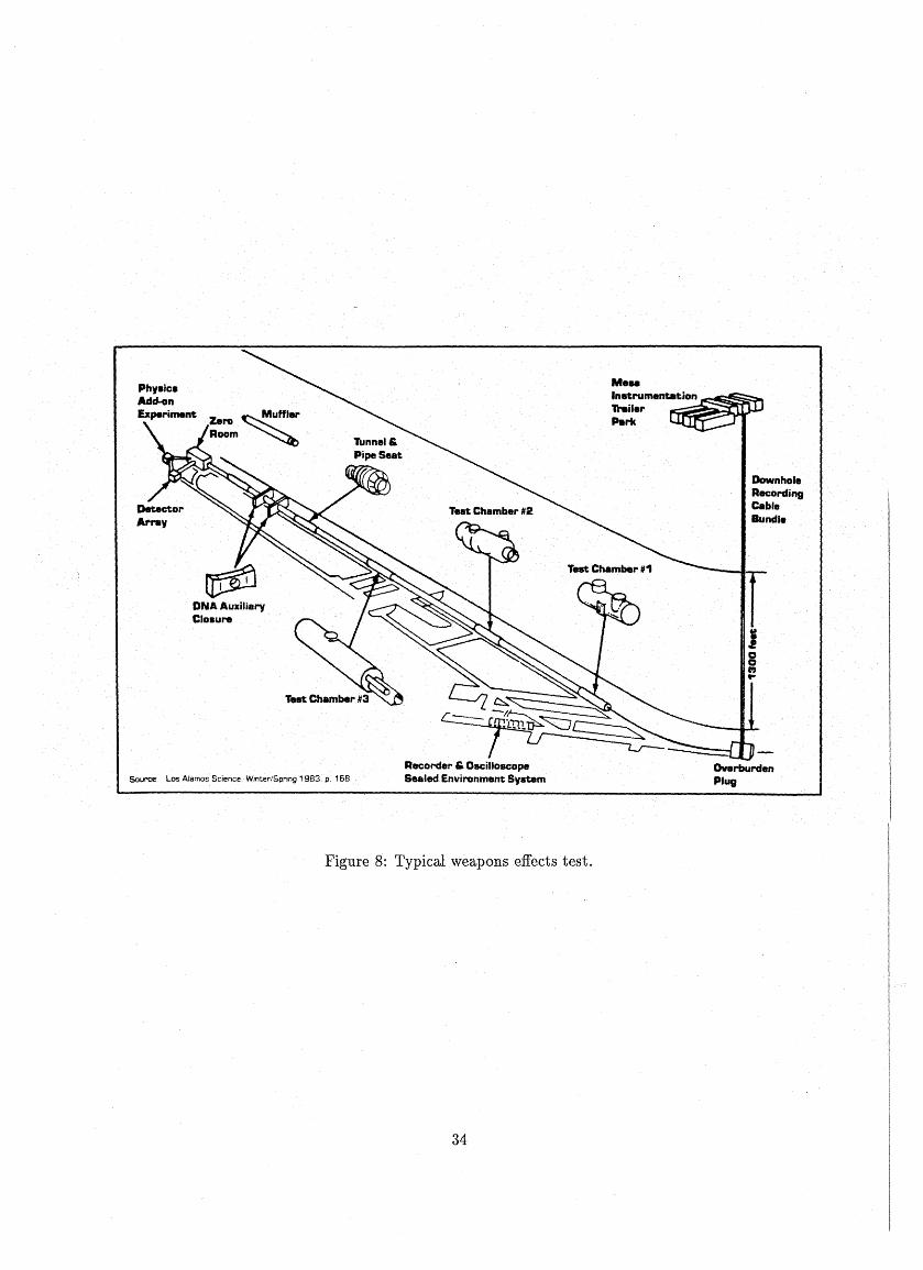
Instead of using the verticalline-of-sight (VLOS) arrangement provided by vertical shafts (seeSection 3.3), weapons effects tests are generaily conducted in horizontal tunnels that are drilleddeep into a mountain. Fig. 8 shows a typical effects test arrangement used by the DNA. Thenuclear device (generally a low-yield device supplied by either LANL or LLNL) is placed insidethe Zero Room at the end of the main tunnel. The Zero Room is connected to a horizontallineof-sight (HLOS) steel pipe that is up to 400 meters long and contains a number of test chambers.Alternatively, each test chamber can be mounted in aseparate HLOS pipe that emerges fromthe Zero Room and runs through one of several side tunnels. Each test chamber is mountedwith experiments and placed at a distance from the nuclear device appropriate to the effect beingstudied. The pipes and chambers may be vacuum pumped to simulate conditions in the upperatmosphere.59
When the nuclear explosion occurs, the emitted radiation (mainly consisting ofx-rays, gamma
58From 3 July 1974 through December 1986, the DOE has announced 189 nuclear tests. Of these, 158 tests(83.6 %) are announced as weapons related, 17 (9.0 %) as weapons effects tests, and 14 (7.4 %) as joint U.S.-U.K.tests. At least 17 unannounced nuclear tests have occured in this period. Most, if not all, of the unannounced andjoint U.S.-U.K. nuclear tests can be assumed to be weapons related.
59Display in the National Atomic Museum, Albuquerque.
33
Phy.ic8Add-onExperiment
DNA Auxilieryelo.ure
Source: Los AJamos Science. Wlnter/Spnng 1983. p. 168
Recorder" OsciJIoscopeSealed Environment System
Me..Instrumentation ~~~;::;iI-lTreilerPttrk
DownholeAecordingCableBundJ.
TJooI'J..
Figure 8: Typical weapons effects test.
34
rays and neutrons) flows down .the HLOS pipe to the test chambers where the experiments areirradiated. Explosion-driven mechanisms elose two or three steel doors positioned in the pipewithin about 30 milliseconds after the nuelear explosion, sealing off the pipe after the explosiongenerated radiation has reached the experiments and before they can be damaged ordestroyedby blast effects or radioactive debris. The entire complex of Zero Room, doors, test chambers,et .cetera, is sealed from the main tunnel by other elosure mechanisms that operate prior todetonation to prevent the release of radioactive materia1.6o
Signals from the experiments are sent by cables to aboveground recording stations. Followingthe test, the military equipment is retrieved from the test chambers and the effects of the nuclearexplosion are evaluated. Among the equipment the United States has exposedto nuclear effects inrecent years are materials and components of the MX and Midgetman systems, reentry vehicles,and entire missiles and communication satellites. One of the most complex effects tests, HuronLanding, on 23 September 1982, used 3,000 data channels to assess 400 separate experiments.61
The cost of a nuclear underground test depends on the type of the test and cOlnplexity ofthe diagnostic instrumentation. A typical weapons related test costs between $6 million and$20 million. Due to the more extensive tunneling and more complex diagnostics needed for aweapons effects test the cost ranges between $40 million and $70 million per effects test.62
3.3 Conductingan underground nuclear test
An underground nuclear test which is conducted in a vertical shaft involves five major phases:63
• Preparation of the test hole.
• Assembly of canisters containing diagnostic instrumentation and the nuclear device.
• Fielding of the test.
• Detonation of the nuclear explosive.
• Retrieval of test results.
The preparation of the test hole begins with selection of a test location. Depending uponthe yield of the nuelear device as weil as upon the type of test and local geological medium,parameters such as the required depth of the shot point, separation from sites of other tests, anddistance from surface structures are fixed.
Large-diameter drill bits are used to drill the test holes. During the years, the diameters ofthe emplacement holes have increased from 0.6 meters to a typical value of 2.5 meters; some testholes have a diameter of up to 3.6 meters. The depth of the hole depends on the yield of the
6°Ibid.61T. B. Cochran, W. M. Arkin, R. S. Norris, and M. M. Hoenig, Nuclear Weapons Databook, Vol. II: U.S. Nuclear
Warhead Production (Cambridge, Mass.: Ballinger, 1987), p. 47.62Ibid., p. 46; N. Joeck and H. F. York, Countdown on the Comprehensive Test Ban, Universityof California,
Institute on Global Conflict and Cooperation, and Ploughshares Fund, Inc., 1986, p. 1.63 Nuclear Test Program, Lawrence Livermore National Laboratory, LLL-TB-57, 1985, p. 6.
35
nuclear deviee and is somewhere between 180 and 700 meters.64 The time needed to drill such ahole is typieally 2 to 5 weeks.
Detailed geologie site investigations are made after the test hole has been drilled to ensurethe containment of the nuclear explosion and its radioactive by-products. Sampies from the coreor from the test hole's wall are taken and analyzed in the laboratory.65
After the Baneberry event of 18 December 1970, in whieh the containment measures failed anda large prompt venting occured that proc1uced off-site radioactivity, the United States initiated amore formal containment program. The DOE's Containment Evaluation Panel (CEP) proceduresare now more rigorous. The required conditions for a test site are:66
• Material properties (e.g.,bulk density, grain density, water content, saturation, porosity,permeability, electrical conductivity, and sonie velocity) similar to those of previously successful test sites.
• A low carbonate content to reduce the generation of noncondensable gases, which can flowaway from the cavity.67
• Generally horizontal stratigraphic bedding, with an absence of major faults nearby.
• A suitable distance from the nearest Paleozoie rocks, which can have high carbonate contentsand can influence cavity growth and shock behavior.
After thenuclear weapon laboratories' containment specialists have approved the containmentcharacteristics of the emplacement hole, it can be used for a nuclear test. A number of holes atthe Nevada Test ,Siteconstitute a sort of an inventory that is to be used when needed.68 When anuclear test is scheduled, the site is prepared for the event by grading the area around the holeand erecting an assembly tower near the emplacement hole.
Each nuclear test requires a variety of diagnostic instruments, such as x-ray spectrometers andgamma ray and neutrondetectors, whieh measure the performance of the test deviee. The variouscomponents of these instruments are designed and fabrieated atthe nuclear weapon laboratories.The instruments are then assembled and placed into an instrumentation canister that is hung inan installation tower at the Las Vegas staging area. The more complex instrumentation canistersare approximately 15 meters long and weigh about 200 tons. After alignment of the instruments,
64Before the signing of the Threshold Test Ban Treaty, even deeper holes (up to 1,800 meters) were used for thehighest-yield test deviees.
65 Researchers are now developing instruments which ean be lowered downhole to measure the geologieal properties, eliminating the needfor retrieving samples from underground (30 Years 01 Technical ExceUence, LawrenceLivermore National Laboratory, 1982, p. 29).
66Nuclear TestProgram, Lawrence Livermore National Laboratory, LLL-TB-57, 1985, p. 7.67If a nuclear explosive were to be detonated in rock with high carbonate content, the heat produced by the
explosion would generate a large quantity of earbon dioxide (C02 ). The resulting gas pressure then could give riseto the possibility of seepage of radioactive materials from the shot cavity.
68Hearings on H.R. 2603 Department of Energy Authorization Legislation (National Security Programs) forFiscal Year 1980 before the Proeurement and Military Nuclear Systems Subcommittee of the Committee on ArmedServices, House of Representatives, 96th Congress, First Session (HASC No. 96-6).
36
the canister is brought by truck to the NTS. The assembly tower near the emplacement holeprovides protection against wind and weather while final installations and alignments are com"'"pleted. Up to 200 coaxial cables69 that are equipped with gas blocks to prevent radioactive gasfrom flowing through the cables connect the diagnostics equipment with recording instrumentshoused in trailers placed in a safe distance from the test site.
After the device canister containing the nuclear device and the associated fhing componentsi8 attached to the instrumentation canister, the assembly tower is removed and huge cranes lowerthe test assembly to the bottom of the emplacement hole. The lowering procedure takes about 8to 10 days with present methods; a new downhole system will reduce this timeto about 2 days.70The emplacement hole is then backfilled with a combination of sand, gravel, and concrete to avoidthe escape of radioaetivy to the atmosphere once the nuclear device i8 detonated. Impermeableepoxy plugs inserted into the hole provide additional protection.71 The backfilling or "stemming"operation currently takes about 2 weeks, because the material poured into thehole has to settlebefore more material can be added.
The arming and firing equipment is housed in the "Red Shack" near the test site. The testdevice i8 detonated by sending a specific sequence of signals from the Control Point to the RedShack.72 Within a few microseconds following the arrival of thefiring signal, the nuclear explosionwill have destroyed and vaporized the diagnostic instruments and cables near the shot point, butby that time the detectors and sensors will have sent their output signals through the cablesto the recording instruments in the trailers or by microwaves to the Control Point ("promptdiagnostics") .
The rock surrounding the expanding incandescentgas cloud, that was once the test device,is immediately vaporized. The shock wave resulting from the explosion compresses and crushesthe rock around the gas cloud completely, cau8ing it to behave like a liquid· ("hydrodynamicalphase"). The velocity with which the shock wave propagates depends on the yield of the explosionand initially exceeds the sound velocity in the rocks. As the 8hock wave propagates further , itsstrength decreases, because its energy is distributed over an increasing area, and its velocitydecreases so that beyond the "strang shock" region, in which the rocks are compressed and
69The number of cables depends on the type and number of instruments installed in the instrument canister.Eachcoaxial cable provides asingle data channel. While these cables have been used since Trinity, they are nowpartially replaced by fiber optics cables that provide eight data channels each. Fiber optics cables have a much higherbandwidth and are much lighter and smalIer than coaxial cables. Furthermore, since they are nonmetallic, theypreclude the interference of spurious signals generated by the nuclear explosion with the recording instruments.Data transfer occurs in the form of light signals that are generated by the diagnostic equipment downhole andconverted into eleetrical pulses by a. photomultiplier at the aboveground recording station.
70 30 Years 0/ Technical ExceUence, Lawrence Livermore National Laboratory, 1982, p. 29.71 As is noted in the Nuclear Weapons Databook, the containment precautions have been successfulless than two
thirds of the time. Of the 630 announced tests at NTS through December 1984, radioactivity was detected on sitein 93 (15 percent) and off site in 136 (22 percent) (T. B. Cochran, W. M. Arlrin, R. S. Norris, and M. M. Hoenig,Nuclear Weapons Databook, Vol.lI: U.S. Nuclear Warhead Production (Cambridge, Mass.: Ballinger, 1987), p. 45;see also: Department of Energy, "Announced United States Nuclear Tests, July 1945 through December 1982",Nevada Operations Office, Office ofPublic Affairs, NVO-209 (Rev. 3), January 1983).
72B. Campbell, R Diven, J. McDonald, B. Ogle, and T. Scolman, "Field Testing - The Physical Proof of DesignPrinciples", Los Alamos Science, Vol. 4, No. 7 (Winter/Spring 1983), p. 164.
37
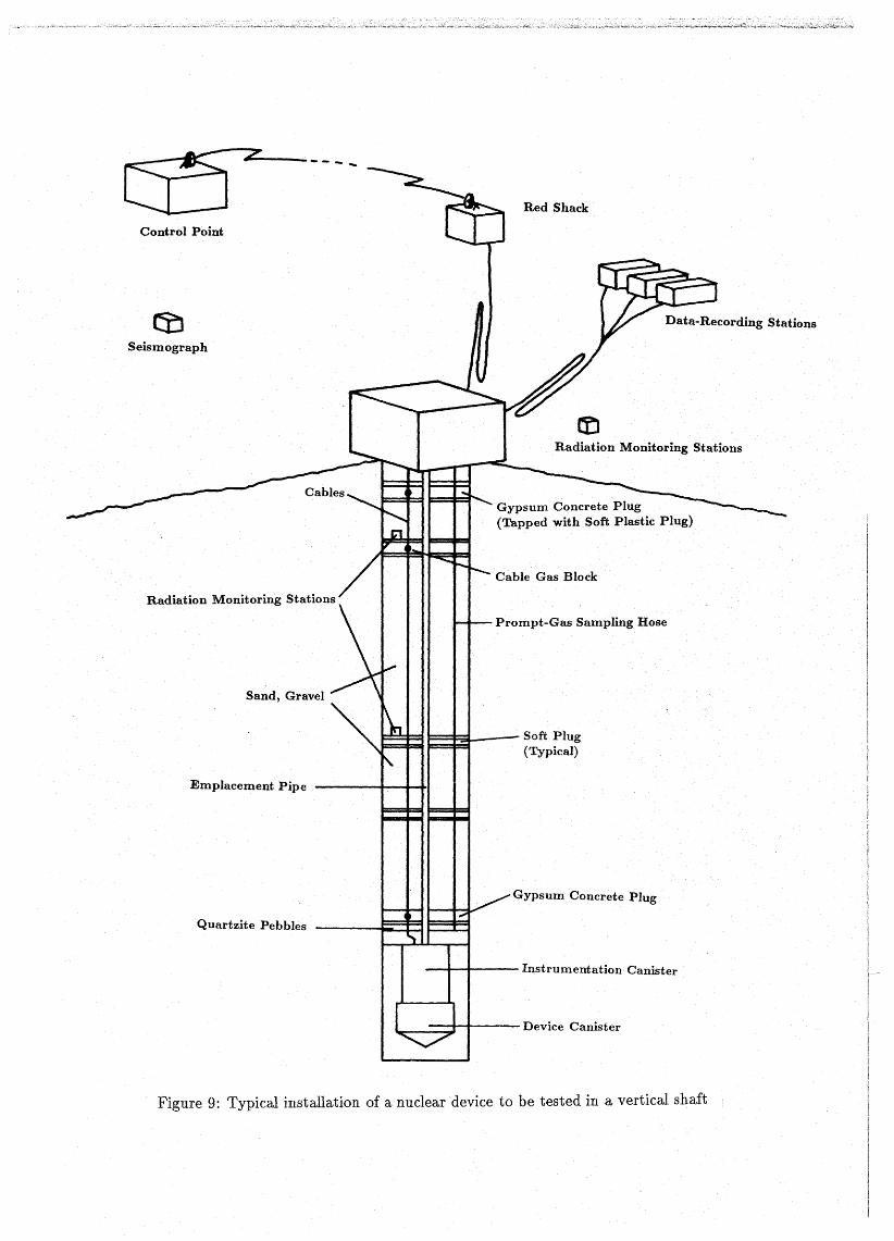
Control Point
z~- ........
Red Shack
Seismograph
Radiation Monitoring Stations
Sand, Gravel
Emplacement Pipe
Gypsum Concrete Plug(Tapped with Soft Plastic Plug)
Cable Gas Block
Prompt-Gas Sampling Hose
Soft Plug(Typical)
Quartzite Pebbles
Gypsum Concrete Plug
- ......--t--- Instrumentation Canister
lr.--==:;r-t---- Device Canister
Figure 9: Typical installation of a nuclear device to be tested in a vertical shaft
caused to behave like a fluid, the rocks are fractured 01' plastically deformed until, finally, theyare deformed elastically, giving rise to thegeneration of seismic waves which spread out in alldirections from the shot point.
When the shock wave reaches the ground surface above the shot point ("Ground Zero"), theground arches upwards (unless the device is a very-low yield one that was buried very deeply).Depending on the yield of the nuclear explosive relative to its emplacement depth the surfacematerial either is blown away ("dirty shot"), leaving a large crater at thetest site,or falls backto approximately the same level as before.
Inside th~ cavity, that has been formed by the expanding gas cloud and that has grown toa size of up to a few tens of meters as boiling rock vaporized from its surface, molten rockdrops down which after eooUng forms asolid puddleof radioactive glassy material. As heat i8eondueted away, the temperature and pressure of the gas inside the eavity deerease until theshattered roek immediately above the eavity begins to fall into the cavity. The void that hasbeen created progressively works its way up. As a result, a eylindrical chimney filled with rubbleis formed. If the surfaee material is too weak to hold its own weight, it falls down into the voidproducing a large subsidenee erater on the ground surfaee. The eollapse time depends on theyield of the nuclear explosive, its depth of. burial, a~d the physical properties of the overlyingmaterial. The surfaee eollapse generally oecurs within a few minutes or hours of the undergroundnucIear explosion. In a few eases where low-yield deviees were buried very deeply, no subsidencecraters were formed 01' the eollapse times have been several months.
Besides the recovery offilm and eomputer-data files from the recording stations in the trailers,the retrieval of test results generallybegins with the acquisition of radioactive sampies from theshot eavity. Gas sampies ean be taken even before the eavity collapses by pumping the gas tothe surface through a heavily armored hose. Slant drilling is used to reeover hoth gaseous andsolid sampies from the explosion area after the cavity haseoilapsed. These postshot drillingoperations that once took more than amonth are now done in less than a week. The samples arereturned to th~ nuclear weapons laboratories for radiochemieal analysis. Together with detailedknowledge ofall the chemical elements in and around the nuclear device prior to its detonation,this analysis· provides informations about the elemental and isotopicspecies produced during thenuclear explosion and henee about the yield of the nuclear explosive and theburn-up of thenuclear fuel.
3.4 Yield Determination
The amount of energy released in a nucIear explosion is called the yield of the nuclear explosive.Yields are usually expressed in terms of kilotons (kt). This energy is equivalent to the energyreleased by the detonation of 1,000 tons of the ehemical explosive Trinitrotoluene (TNT). Onethousand kilotons are also referred to as 1 MT (megaton).
The yield of a nuclear device can be predicted by experieneed scientists if the amount offissile and fusion material as weil as the design characteristics are known. Generally, however, theactual yield as measured after the device has been detonated, differs from the predicted value.Depending upon both the design changes that have been made eompared to previously tested
39
designs and the quality of theoretical models, the uncertainty in yield can be as large as a factorof about two. A number of cases is known where the actual yield of the test device has beeneither over- or underestimated.73
Several methods can be applied to determine the actual yield of a nuclear explosion. Thefoilowing paragraphs give abrief outline of these methods.
3.4.1 Radiochemical Method
The most precise method to determine the yield of an underground nuclear explosion is anaccurate chemical analysis of the radioactive products of the explosion. Gaseous and solid sampieshave to be recovered from the shot area and analyzed in the laboratory as soon as possible.74
The precision of this method is reported to be approximately ±10%.75 To achieve this precision,an accurate knowledge of the weapon design as weil as of the chemical elements to be found inthe immediate environment of the device (device and instrumentation canisters, stemming androck materials, etc.) prior to Hs detonation is required. To distinguish the yield calculated bythis method from other energy measures, it is cal1ed the radiochemical yield (Yc ) of the nuclearexplosive. Usually, the officially announced yield of a nuclear test (if there is any) is based on ~.
The radiochemical method is applicable only if the investigator has access to the shot cavityand if he knows the details mentioned above. Hence, this method is not usable for the yielddetermination of underground nuclear tests occuring in foreign countries.
In addition to the yield, the radiochemical method also provides information about the performance of the nuclear device that has been tested, e.g., the burn-up ratios of th~ fissile materialand fusion fuel.
3.4.2 Methods Using Nucleaz- And Thermal Radiation Measurements
Methods· have been developed to obtain the yield of a nuclear device from accurate measurementsof the neutron spectrum by careful observations of the emerging gamma rays. A pinhole cameramounted in the instrumentation canister can be used to take two-dimensional pictures of theactual shape and size of the reacting fissile material of a fission deviceor of the burning fuel ina thermonuclear device. A fraction of gamma rays and neutrons emerging from the explodingdevice is transmitted through the device material, such as remnants of the high explosive andouter casing, and reach a detector after passing through a tiny pinhole in an otherwise thick pieceof shielding. The thermal radiation is. eliminated by a thin metal screen between the device andthe detector. It i8 even p08sible by use of variou8 schemes to produce gamma rays or neutron
73The fact that the aetual yield differs from the predicted yield does not necessarily mean that the test devicedoes not fulfill its requirements, because the performance of the device is often determined by faetors other thanyield.
74See Seetion 3.3 for a description of sample-aquisition techniques.75 A value of ±10% is thus the best accuracy with which the yield of a nuclear weapon can be stated. A warhead
which is designated as, e.g., a 150-kt warhead, can thus release an amount of energy in the range of 135 kt to165 kt.
40
pietures of selected energies or to get several frames of motion of the reacting region separatedby a few billionths ofa second.76
Although nuclear testing in the atmosphere is not done any longer , it should be noted that theyield of an air burst can be estimated by measuring the time between the two thermal radiationmaxima whieh are characteristie for a nuclear explosion.
3.4.3 Hydrodynamical Methods
Another way to estimate the yield of a nuclear explosion is to measure the rate of energy transferinto the medium surrounding the nuclear deviee. For as long as atmospherie testing was done,observation of the expansion velocity of the fireball as photographed by super-high-speed moviecameras gave reliable yield determinations. In underground explosions, wherea fireball cannotbe observed, the variation in peak pressure in the shock wave or its propagation through therocks fairly elose to the shot point can be measured and used as an indieator for the amount ofenergy released. The measurements can be made using calibrated pressure gauges, which must berugged enough towithstand the violent shock wave, or sensors, whieh measure the shock arrivaltimes as a function of distance. To obtain reliable yield estimates, the properties of the geologiemedium in which the explosion occurs must be known.
Shock· arrival times can be measured with discretely spaced sensors, such as electrieal contactors or ferroelectric and piezoelectric crystals, or by usinga coaxial cable as a continuous sensingline. Two partieular techniques applicable for continuously measuring the shock propagation havebecome known as SLIFER77 and CORRTEX78.
Both SLIFER and CORRTEX make us~ of a coaxial cable that is embedded i~ the rocks ahovethe nuclear device to be tested in such a direction that the shock front will move monotonieallyalong the cable from maximum length to minimum length. The cable i8 usually emplaced in thedeviee emplacement hole so that it is radially aligned with the center of explosion. However, theuse of a "satellite" hole (about 30 cm in diameter) that is drilled parallel to the deviee emplacementhole is also possible as long as the distance of the cable from the shot point is known. When thenuelear deviee detonates, the cable is crushed and shortened by the shock wave emanating fromthe shot point. If thecable is physieally weak compared to the shock amplitude and if it can beregarded as a small perturbation in the surrounding medium, the cable is shorted at the shockfront, and the rate by which the cable length changes is a measure of the velocity of the shockwave which is, in turn, a measure of the yield of the nuc1ear explosion.
The SLIFER and CORRTEX systemsdiffer in the way the change of cable length is determined. The SLIFER system79 uses the coaxial cable as the inductive element of an oscillator.Fig. 10 is a schematie representation of the resonant circuit used by SLIFER. Li and Ci is theinternal inductance and interna! capacitance of the oscillator, respectivelYi Lz is the inductance
76B. Campbell, B. Diven, J. McDonald, B. Ogle, and T. Scolman, "Field Testing - The Physical Proof of DesignPrinciples", Los Alamos Science, Vol. 4, No. 7 (Winter/Spring 1983), p. 164.
77SLIFER = Shorted Location Indicator by Frequency of Eleetrical Resonance.78 CORRTEX = COntinuous. Reflectometry for Radius versus Time EXperiment.79For more details see: M. Heusinkveld and F. Holzer, "Method of Continuous Shock Front Position Measure
ment", The Review of Scientific Instruments, Vol. 35, No. 9, 1964, p. 1105.
41
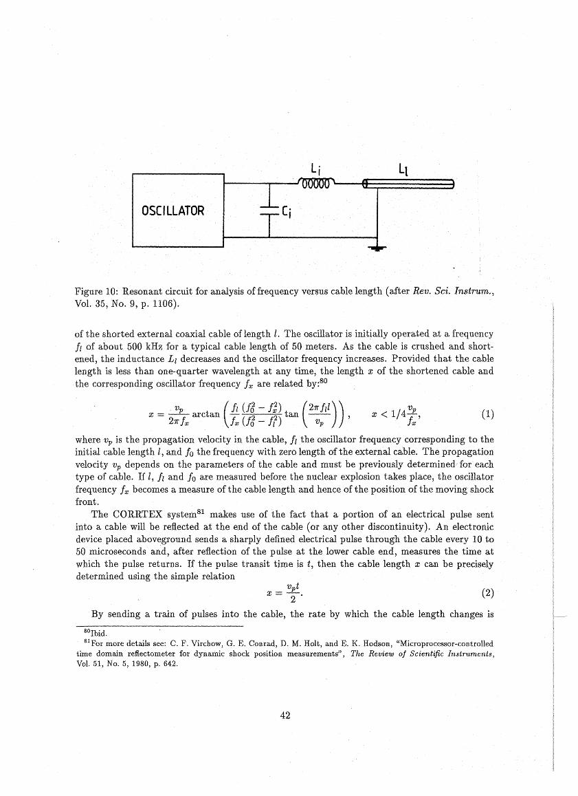
Li
OSCILLATOR
Figure 10: Resonant circuit for analysis of frequency versus cable length (after Rev. Sei. Instrum.,Vol. 35, No. 9, p. 1106).
of the shortedexternal coaxial cable of length l. The oscillator is init~ally operated at a frequencyfl of about 500 kHz for a typical cable length of 50 meters. As the cable is crushed and shortened, the inductance LI decreases and the oscillator frequency increases. Provided that the cablelength is less than one-quarter wavelength at any time, the length x of the shortened cable andthe corresponding oscillator frequency 1x are related by:80
, vp (11 (f3 - 1;) (211" fl l ))x =21r1x arctan. 1x (13 - Ir) tan -;;;- . , (1)
wherevp i8 the propagation velocity in the cable, 11 the oscillator frequency corresponding to theinitialcable length I, and 10 the frequency with zero length of the external cable. The propagationvelocity vp depends on the parameters of the cable and must be previously determined/ for eachtype of cable. If I, fl and 10 aremeasured before the nuclear explosion takes place, the oscinatorfrequency 1x becomes a measure of the cable length and hence of the position of the moving shockfront.
The CORRTEX system81 makes use of the fact that a portion of an electrical pulse sentinto a cable will be reflected at the end of the cable (or any other discontinuity). An electrol1icdevice placed abovegroundsends a sharply defined electrical pulse through the cable every 10 to50 microseconds and, after reflection of the pulse at the lower cable end, measures the time atwhich the pulse returns. If the pulse transit time is t, then the cable length x can be preciselydetermined using the simple relation
(2)
By sending a train of pulses into the cable, the rate by which the cable length changes is
80Ibid.81For more details see: C. F. Virchow, G. E. Conrad, D. M. Holt, and E. K. Hodson, "Microprocessor-controlled
time domain reflectometer for dynamic shock position measurements", The Review 0/ Scientific Instruments,Vol. 51, No. 5, 1980, p. 642.
42
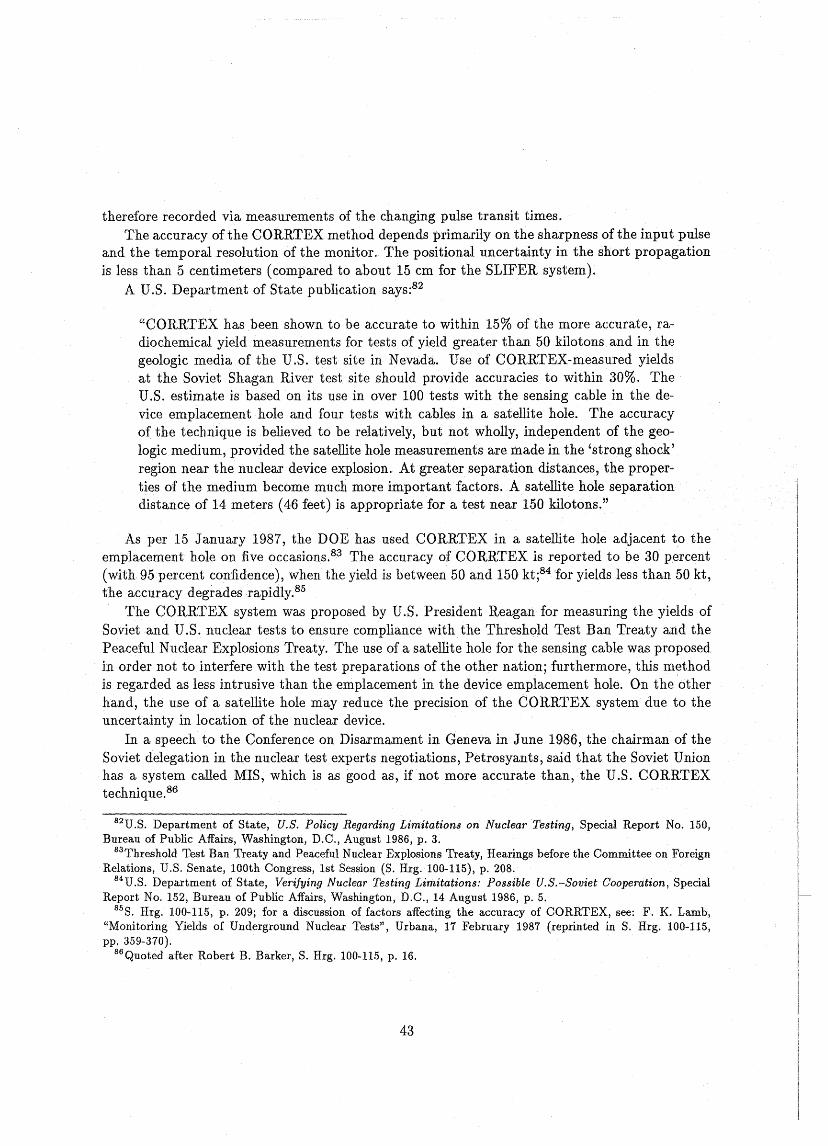
therefore recorded via measurements of the changing pulse transit times.The accuracy of the CORRTEX method depends primarily on the sharpness of the input pulse
and the temporal resolution of the monitor. The positional uncertainty in the short propagationis less than 5 centimeters (compared to about 15 cm for the SLIFER system).
A U.S. Department of State publication says:82
"CORRTEX has been shown to be accurate to within 15% of the more accurate, ra~
diochemical yield measurements for tests of yield greater than 50 kilotons and in thegeologie media of the U.S. test site in Nevada. Use of CORRTEX~measured yieldsat the Soviet Shagan River test site should provide accuracies to within 30%. TheU.S. estimate is based on its use in over 100 tests with the sensing cable in the de~
viee emplacement hole and four tests with cables in a satellite hole. The accuracyof the technique is believed to be relatively, but not wholly, independent of the geologie medium, provided the satellite hole measurements are made in the 'strong shock'region near the nuclear device explosion. At greater separation distances, theproperties of the medium become much more important factors. A satellite hole separationdistance of 14 meters (46 feet) is appropriate for a test near 150 kilotons."
As per 15 January 1987, the DOE has used CORRTEX in a satellite hole adjacent to theemplacement hole on five occasions.83 The accuracy of CORRTEX is reported to be 30 percent(with 95 percent confidence), when the yield is between 50 and 150 kt;84 'for yields less than 50 kt,the accuracy degrades rapidly.85
The CORRTEX system was proposed by U.S. President Reagan for measuring the yields ofSovietand U.S. nuclear tests to ensure compliance withthe Threshold Test Ban Treaty and thePeaceful Nuclear Explosions Treaty. The use of a satellite hole for the sensing cable was proposedin· order not to interfere with the test preparations of the other nation; furthermore, this methodis regarded as less intrusive than the emplacement in the device emplacement hole. On the otherhand, the use of a satellite hole may reduce the precision of the CORRTEX system due to theuncertainty in location of the nuclear deviee.
In a speech to the Conference on Disarmament in Geneva in June 1986, the chairman of theSoviet delegation in the nuclear test experts negotiations, Petrosyants, said that the Soviet Unionhas a system called MIS, which is as good as, if not more accurate than, the U.S. CORRTEXtechnique.86
82U.S. Department of State, U.S. Policy Regarding Limitations on Nuclear Testing, Special Report No. 150,Bureau of Public Affairs, Washington, D.C., August 1986, p. 3.
83Threshold Test Ban Treaty and Peaceful Nuclear Explosions Treaty, Hearings before the Committee on ForeignRelations, U.S. Senate, 100th Congress, 1st Session (S. Hrg. 100-115), p. 208.
84U .S. Department of State, Verifying Nuclear Testing Limitations: Possible U.S.-Soviet Cooperation, SpecialReport No. 152, Bureau of Public Affairs, Washington, D.C., 14 August 1986, p. 5.
85S. Hrg. 100-115, p. 209; for a discussion of factors affecting the accuracy of CORRTEX, see: F. K. Lamb,"Monitoring Yields of Underground Nuclear Tests", Urbana, 17 February 1987 (reprinted in S. Hrg. 100-115,pp. 359-370).
86Quoted after Robert B. Barker, S. Hrg. 100-115, p. 16.
43
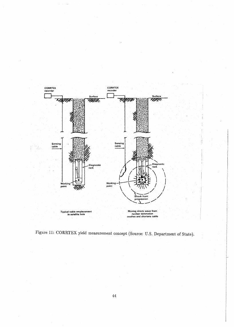
CORRTEXrecorder
CORRTEXrecorder
Sensingcable
Sensingcable-
Workingpoint
Typical cable emplacementin satellite hole
Workingpoint
\\1
\ /1\\ / /" )~,..:/ /"" progression /'
'-~--
Moving shock wave tromnuclear detonation
crushes and shortens cable
Figure 11: CORRTEX yield rneasurernent concept (Source: D.S. Departrnent of State).
44
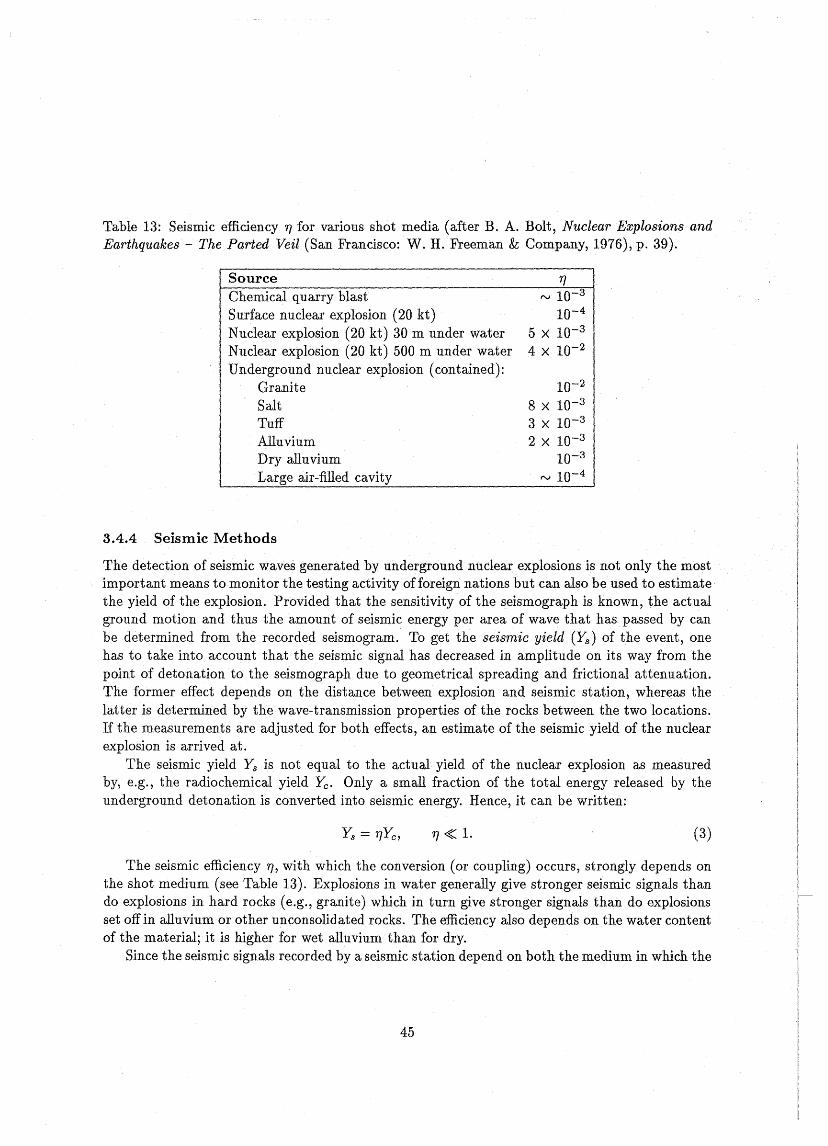
Table 13: Seismic efficiency 'rJ for various shot media (after B. A. BoIt, Nuclear Explosions andEarthquakes - The Parted Veil (San Francisco: W. H. Freeman & Company, 1976), p. 39).
SourceChemical quarry blastSurface nuc1ear explosion (20 kt)Nuclear explosion (20 kt) 30 m under waterNuclear explosion (20 kt) 500 m under waterUnderground nuclear explosion (contained):
GraniteSaltTuffAlluviumDry alluviumLarge air-filled cavity
3.4.4 SeismicMethods
rv 10-3
10-4
5 X 10⁻³
4 X 10⁻²
10-2
8 X 10⁻³
3 X 10⁻³
2 X 10⁻³
10-3
rv 10-4
The detection of seismic waves generated by underground nuclear explosions is not only the mostimportant means to monitor the testing activity offoreign nations but canalso be used to estimatethe yield of the explosion. Provided that the sensitivity of the seismograph is known, the actualground motion and thus the amount of seismic energy per area of wave that has passed by canbe determined from the recorded seismogram. To get the seismic yield (Ys ) of the event, onehas to take intoaccount that the seismic signal has decreased in amplitude on its way frorrl thepoint of detonation to the seismograph due to geometrical spreading and frictional attenuation.The former effect depends on the distance between explosion and seismic station, whereas thelatter is determined bythe wave-transmission properties of the rocks between the two locations.If the measurements are adjusted for both effects, an estimate of the seismic yield of the nuclearexplosion is arrived at.
The seismic yield Ys is not equal to the actual yield of the nuclear explosion as measuredby, e.g., the radiochemical yield Yc • Only a small fraction of the total energy released by theunderground detonation is converted into seismic energy. Hence, it can be written:
'rJ <t: 1. (3)
The seismic efficiency 'rJ, with which the conversion (or coupling) occurs, strongly depends onthe shot medium (see Table 13). Explosions in water generally give stronger seismic signals thando explosions in hard rocks (e.g., granite) which in turn give stronger signals than do explosionsset off in alluvium or other unconsolidated rocks. The efficiency also depends on the water contentof the material; it is higher for wet alluvium than for dry.
Since the seismic signals recorded by a seismic station depend on both the medium in which the
45
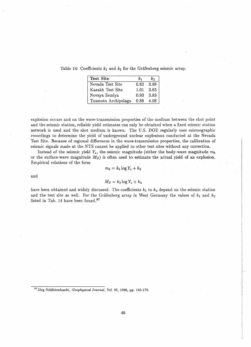
Table 14: Coefficients k1 and k2 for the Gräfenberg seismic array.
Test Site k1 k2
Nevada Test Site 0.82 3.98Kazakh Test Site 1.01 3.85Novaya Zemlya 0.93 3.83Tuamotu Archipelago 0.89 4.08
explosion occurs and on the wave-transmission properties of the medium between the shot pointand the seismic station, reliable yield estimates can only be obtained when a fixed seismic stationnetwork is used and the shot medium is known. The U.S. DOE regularly uses seismographicrecordings to determine the yield of underground nuclear explosions conducted at the NevadaTest Site. Because of regional differences in the wave-transmission properties, the callbration ofseismic signals made atthe NTS cannot be applie<;l to other test sites without any correction.
Instead of the seismic yield Ys , the seismic magnitude (either thebody-wave magnitude mb
or the surface-wave magnitude Ms) is often used to estimate the actual yield of an explosion.Empirical relations of the form
andMs = k3 logYc +k4
have been obtained and widely discussed. The coefficients k1 to k4 depend on the seismic stationand the test site as weil. For the Gräfenberg array in West Germany the values of k1 and k2
listed in Tab. 14 have been found.87
87 Jörg Schlittenhardt, Geophysical Journal, Vol. 95, 1988, pp. 163-179.
46
List of lANDS Working-Papers!Liste der lANDS-Arbeitspapiere - 1989:
IANUS-1/1989:Kanke1eit, Egbert, "Bericht zur. Waffentauglichkeit 'Von Reaktorplut0nium" , Darmsta.dt, 1986
IANUS-2/1989: .Scheffran, JÜtgen, "Sicherheit und Stabilitä.t - Versuch einer interdisziplinärenBegrüfserklärung", Darmstadt, April 1989
IANUS-3/1989: IANUS-Working-Papers/IANUS-Arbeitspapiere, Abstracts in English
IANUS-4/1989:· R~chert, Uwe, IANUS-BibliothekThesaurus, Darmstadt, Oktober 1989
IANUS-.5/1989: Reichert, Uwe, "Kernwaffen der dritten Generation", Darmstadt,Aprll1989" .
IANUS-6AI1989: Schaper, Annette, "Can Arms ControlAlready Start atthe Early Sta.geofResearch .and Deve1opment1-·An Investigation of the· Example of Inertial ConfinementFusion", Darmstadt, Oktober 1988
IANUS-613/1989:Schaper, Annette,"Kann Riistungslrontro1le schon in deJIl friihen.St.:;dium. von Forschung und Entwicklung einer neuenTechnologie einsetzen1 - Be1Spl
Trägheitseinschlußfusion" , Darmstadt, Oktober 1988
IANUS-7/1989: Schaper, Annette, "ICF-Experimente mit kernwa.f[enähnlichenMatena.lien", Darmstadt, März 1989
IANUS-8/1989: Schaper,Annette, "Die Rolle von Forschung und Entwicklung in;'erItüstungsdynamik", Darmstadt,Mai 1989 und "Die Begrenzung rüstungsrelevanter orschungund Entwicklung", Darmstadt, Juni 1989
IANUS-911989:.Ipsen, Dirk, "Der Militär-Industrie-Komplex (MIK)" ,in: "fuforma.tionsdienst Wissenschaft und Frieden", Nr.2, 7.Jg., Seite 31-34, Darmstadt, Mai .1989
IANUS-10/1989: Kalinowski, Martin B., "Verwendbarkeit. und Produktion ~onTritumfürKernwaffenprogramme" , Darmstadt, 1989
IANUS-l1/1989: Ka.1inowski, Martin B., "Nuclear Weapons Uses of Tritium and Multi-lateral Control Measures", Darmstadt 1989 .
"IANUS-12/1989: Nixdorff, Kathryn, "New Potentials in the Area. of Biological ~eapon~:Revised edition of an article. appearing in: C.Hüttig (Hrsg.), "Rüstungstechn.ik undterna.tionale Sich.erheitspolitik", Band 45 der Schriftreihe der TH Darmstadt, D armsta.dt,1989
IANUS-13/1989: Bender, Woligang, "Kompetenz der Betroffenen - Heuristik d~r :FUrcht·~ Institutionen der Meinungserarbeitung", Da.mstadt, Oktober 1989
1
1
1
1
1
1
1
1
1
1
1
1
1
1
1
1
1
1
1
List of IANUS Working-Papers/Liste der IANUS-Arbeitspapiere- 1990:
IANUS-1/1990: IANUS-Zwischenbericht "Zwei Jahre IANUS: Struktur, Ergebnisse undPerspektiven", Darmstadt, April 1990
IANUS-2/1990: Reichert,Uwe, "Warhead·Development and Nuclear Testing", Darmstadt, Mai 1990
IANUS-3/1990: IANUS-Arbeitsbericht, "Einf1ußfaktoren der Rüstungsdynamik" , Darmstadt, Mai 1990
IANUS-4/1990: IANUS-Arbeitsbericht, "Rüstungsrelevante Technologien- Material zursystematischen Beurteilung", Darmstadt, Mai 1990
IANUS-5/1990: Scheffran, Jürgen, "031 andNew Generations of NuclearWeapons -TheUncertain Connection", Darmstadt, Januar 1990
IANUS-6/1990:Hammer,Volker;Kremer, Marion; Lutz, Günther,·· "Risiko-orientierteSystementwicklung" , Darmstadt, Juni 1990
IANUS-7/1990: Nixdorff, Kathryn und Stumm, Isolde, "Ambivale:nceof Basic MaterialUsing TechniquesofGenetic Engineering for the Development ofVaccines", April 1990·
IANUS-8/1990: Bender, Wolfgang und Stumm, Isolde, "Was treibt die Rüstungsdynamikvoran?-Ein Einstieg in dieses Thema im Hinblick auf biologische Waffen", April 1990
IANUS-9/1990: Stumm, Isolde, "Möglichkeiten und Grenzen, die die Gentechnologie imHinblick auf.militärische Anwendung von Biowaffen bietet", April 1990
IANUS-10/1990: Kalinowski, Martin, "Technical Problems with SafeguardingTritium",Juli 1990
IANUS-11/1990: IANUS-Arbeitsbericht "Erfahrungen mit drei interdisziplinärenSeminaren" , 34 Seiten
Kalinowski, Martin, "Seminar "Verantwortung der Wissenschaft - Verantwortung derTechnik" im WS 1988/1989 - Eine Auswertung mit Empfehlungen", Juni 1990
Bargmann, Holger; Benner, Ulrike; Hense, Bernd; Hille, Peter;Kalinowski, Martin, "Probleme der fachübergreifenden Lehre - Technikfolgenabschätzung und Technikgestaltungin einem interdisziplinären Seminar an derTH Darmstadt" ,Mai 1990
Engelmann, Wilfried; Kalinowski, Martin; Kremer, Marion und Scheffran, Jürgen, "Konfliktdynamik und Konfliktmodelle in der Sicherheitspolitik - Auswertung der interdisziplinären Seminars im WS 1989/1990", Juli 1990
2