Embed Size (px)
Citation preview
Nanoscale
PAPER
Cite this: Nanoscale, 2019, 11, 4803
Received 3rd December 2018,Accepted 12th February 2019
DOI: 10.1039/c8nr09747j
rsc.li/nanoscale
Large area metal micro-/nano-groove arrays withboth structural color and anisotropic wettingfabricated by one-step focused laser interferencelithography†
Hao Wu,a Yunlong Jiao, a Chenchu Zhang,b Chao Chen,a Liang Yang,a Jiawen Li,*a
Jincheng Ni,a Yachao Zhang,a Chuanzong Li,c Yiyuan Zhang,a Shaojun Jiang,a
Suwan Zhu,a Yanlei Hu,a Dong Wu *a and Jiaru Chua
Artificial bioinspired surfaces are attracting increasing attention because of their fascinating characteristics,
such as the structural color of a butterfly wing and the anisotropic wetting of a rice leaf. However, realiz-
ation of the multicolor biomimetic metal surfaces with controlled anisotropy by using a simple, in-
expensive and efficient method remains a challenge. Herein, we propose a focused laser interference
lithography processing method, which has sufficient energy density and high processing efficiency to
directly fabricate the groove structures on the metal surface. The surface is multicolor due to the diffrac-
tion grating effect of the regular groove structures, and exhibits anisotropic wetting due to its single-
direction morphology. The influence of the observation angle on the diversity of colors and the aniso-
tropic wetting under different heights and periods of grooves have been quantitatively investigated. A
variety of patterns (e.g., leaf, crab, windmill, letter and so on) can be processed on various metals (e.g.,
stainless steel, Ti, Ni, Cu, Fe, Zn and so on) by this focused laser interference lithography because of its
excellent flexibility and wide range of suitable materials. This multi-functional metal surface has broad
applications in identification code, decorative beautification, anti-counterfeiting, information storage,
bionic application design and so on.
1. Introduction
Bioinspired surfaces have continuously attracted enormousinterest due to their unusual physical and chemical properties,which can be utilized for biological media,1 drag reduction,2
microfluidic devices,3 decorative beautification,4 solar cells,5
and so on. Among the above, two typical properties of bio-inspired surfaces are structural color and anisotropic wetting.The structural color is inspired by insect wings or bird feath-ers, and the anisotropic wetting is inspired by rice leaf,trionum flower, duck feather, or shark skin.6–12 These twofascinating functions are all derived from the surface micro/
nanostructures of biological species. In order to mimic bio-logical species, a variety of micro/nano-processing methodsare used to fabricate micro/nanostructures to realize bio-inspired surfaces. For example, Wang et al. used a femtosecondlaser to print nanovoids on metal films, which can reproducedifferent pure colors based on plasmonic coloration.13 Xiaoet al. reported a bioinspired structural color film fabricated byself-assembly of synthetic melanin nanoparticles to reproducecolors of bird feathers.14 Vorobyev et al. used femtosecondlaser surface structuring techniques to induce periodic surfacestructures on metals (LIPSS), which are colorful due to thegrating effect.15 By multiple exposure of two beam laser inter-ference with angle variation and period modulation, Abid et al.realized three levels of biomimetic hierarchical structures withstructural color and superhydrophobicity on a polymer.16 Yonget al. realized an anisotropic wetting surface by using a line-by-line femtosecond laser scanning to process microgroove arrayson polydimethylsiloxane (PDMS).17 Cheng et al. preparedarrays of micropillars on the shape memory polymer viareplica-molding method to mimic the structures on the riceleaf.18 Liu et al. adopted femtosecond laser single-pointscanning to realize large grooves (∼50 µm) with anisotropic
†Electronic supplementary information (ESI) available. See DOI: 10.1039/c8nr09747j
aCAS Key Laboratory of Mechanical Behavior and Design of Materials, Department of
Precision Machinery and Precision Instrumentation, University of Science and
Technology of China, Hefei 230026, China. E-mail: [email protected],
[email protected] of Industry and Equipment Technology, Hefei University of Technology,
Hefei 230009, ChinacSchool of Instrument Science and Opto-Electronics Engineering, Hefei University of
Technology, Hefei 230009, China
This journal is © The Royal Society of Chemistry 2019 Nanoscale, 2019, 11, 4803–4810 | 4803
Publ
ishe
d on
14
Febr
uary
201
9. D
ownl
oade
d by
Uni
vers
ity o
f Sc
ienc
e an
d T
echn
olog
y of
Chi
na o
n 4/
15/2
019
5:39
:15
AM
.
View Article OnlineView Journal | View Issue
wetting on a copper surface.19 However, these fabrication pro-cesses are complex multistep or one-step with low efficiency(single point scanning) processes. Some of the fabricatedmicrostructures are irregular due to their self-induced for-mation mechanism.15 Therefore, it still remains a significantchallenge to simultaneously realize multifunctional surfaceswith structural color and anisotropic wetting on hardmaterials, such as metal which has broader application ratherthan a polymer, with the use of a simple, inexpensive andefficient method. Laser interference lithography (LIL) has beenused for decades and constantly improved as one of the mostpowerful yet relatively inexpensive methods for creating large-area patterns that range from sub-micron to micronscales.16,20,21 By adjusting the amount of laser interferencebeams, light intensity, phase of the laser, incident angle,polarization, etc., 1D, 2D, and even 3D periodic structures canbe obtained. Nevertheless, the processing materials of the LILin the existing reports are almost all based on soft materialssuch as polymers.
Herein, we proposed a focused laser interference lithogra-phy processing method, which has sufficient energy density todirectly fabricate the groove structures on various metal
surfaces. This multifunctional bioinspired surface has bothdazzling structural colors and anisotropic wetting function.We quantitatively investigated the influence of the observationangle on the diversity of structural colors on the center of theprocessed metal surface when an incident white light anglewas fixed. We also systemically investigated anisotropicwetting behavior on groove structures with different periodsand heights. It was found that the anisotropic wetting isstrongly dependent on the height and weakly dependent onthe period when the period was about the magnitude ofseveral micrometers. Based on the investigated fabricationparameters, we can realize multicolor biomimetic metal sur-faces with controlled anisotropy.
2. Results and discussion2.1. Construction of focused laser interference lithographysystem and analysis of groove formation mechanism
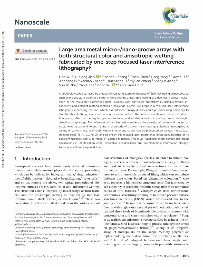
Fig. 1a illustrates the experimental setup for different grooveson the mirror polished 316L stainless steel surface by focusedtwo-beam laser interference lithography. After laser beam
Fig. 1 Experimental setup and the formation mechanism of controllable grooves on the stainless steel surface. (a) Schematic of focused two-beaminterference fabrication using nanosecond laser. (b) Simulation diagram of light intensity distribution (20 × 20 µm2). (c) SEM image of grooves on thestainless steel surface. (d) AFM image of grooves on the stainless steel surface (20 × 20 µm2). (e) Mechanism of laser shock wave and debris depo-sition process, which causes the formation of grooves.
Paper Nanoscale
4804 | Nanoscale, 2019, 11, 4803–4810 This journal is © The Royal Society of Chemistry 2019
Publ
ishe
d on
14
Febr
uary
201
9. D
ownl
oade
d by
Uni
vers
ity o
f Sc
ienc
e an
d T
echn
olog
y of
Chi
na o
n 4/
15/2
019
5:39
:15
AM
. View Article Online

expansion, the output laser spot was shaped into a 1 × 1 cm2
square by square aperture. Then, the laser was split into twobeams which had the same energy. In order to get enoughenergy density to process the stainless steel surface, twobeams were converged into the 1 × 1 mm2 squares by twoconvex lenses. By tightly adjusting the optical path length, thebeams were overlapped on the sample both temporally andspatially to form a periodic light intensity pattern by the inter-ference. As the light intensity distribution simulation (Fig. 1b)shows, the periodic light intensity pattern is composed ofstripes with the light intensity changing continuously from 0I0 to 4 I0 (I0 is defined as the light intensity of each beam). Thestripes period, ds = λ/(2sin θ), is determined by the incidentangle θ and the laser wavelength λ. Given θ = 7.04°, the theore-tical stripe period ds is 1.45 µm. Judging from the top viewSEM image (Fig. 1c), the period dg of the grooves on the pro-cessed sample is about 1.46 ± 0.01 µm, which is consistentwith the theoretical stripes period ds. Due to the strict uni-formity of the light intensity distribution caused by the inter-ference, the grooves generated in the single exposure regionare more uniform and continuous than that by LIPSS.15,23 Asshown in the AFM image (Fig. 1d), the height of the grooves issub-200 nm and the cross section has a sinusoidal shape.Fig. 1e schematically shows the formation process of thegrooves on the stainless steel surface. During laser irradiation,the laser-induced plasma was expanded to produce the shockwave, high temperature and high pressure at the interface.22
The stainless steel surface was melted, and the higher the lightintensity the deeper the melting occurred. Under the syner-getic effect of shock wave and debris deposition, the grooveswith sinusoidal cross sections were formed.
2.2. Regulation of groove characteristics
The characteristics (e.g., period, height) of the grooves on thestainless steel surface can be regulated by changing the proces-sing parameters. Four kinds of period 0.62 µm, 0.92 µm,1.16 µm and 1.45 µm were obtained under θ = 16.67°, 11.10°,8.83° and 7.04°, respectively, which is consistent with thetheoretical calculations. The height of the grooves, as one ofthe most important parameters of grooves, was studied indetail. Fig. 2d shows the relationship between groove heightand laser fluence with the 100 laser shots and the grooveperiod of 1.45 µm. The laser fluence was 0.215 J cm−2,0.335 J cm−2 and 0.404 J cm−2 to form the groove heights of29.96 nm (Fig. 2a), 74.64 nm (Fig. 2b) and 128.20 nm (Fig. 2c),respectively. The larger the laser fluence the higher the grooveis. Laser fluence that is too small will lead to irregular grooves(Fig. 2a). If the laser fluence increases, the thickness of themolten metal will be greater and more debris will be depositedso that the groove height increases. Fig. 2 h shows the relation-ship between groove height and number of laser shots withthe laser fluence of 0.404 J cm−2, and the groove period of1.45 µm. The groove heights 41.26 nm (Fig. 2e), 80.20 nm(Fig. 2f) and 193.39 nm (Fig. 2g) were obtained under the 30,70 and 130 laser shots, respectively. It is obvious that the effectof smaller number of laser shots on the irregular groove mor-
phology (Fig. 2e) is similar that of the insufficient laserfluence. Too large laser fluence (>0.45 J cm−2) or number oflaser shots (>140) will lead to poor groove morphology, whilethe groove height will stay constant (∼200 nm). Hence, byadjusting the incident angle θ, the laser fluence and thenumber of laser shots, controllable grooves with differentperiods and heights can be fabricated on the stainless steelsurface.
Although the sample with micro/nano grooves wasobtained, the area of single processing was only 1 × 1 mm2,which seems small for some particular applications. A two-dimensional translation precision stage was used to move thesample to splice the single processing area into multiple largepatterns. Larger surface areas (e.g., 6.5 × 7 cm2) can beobtained through the combination of the control of theshutter and the movement of the two-dimensional XY trans-lation stage. Due to the high fabrication efficiency of this inter-ference method, a fully filled 2 × 2 cm2 square can be realizedin 400 seconds, which is much faster than the single pointfemtosecond laser scanning methods (such as LIPSS, 1000seconds).23 However, the pattern edges are usually jagged asthe minimum exposed area is 1 mm2. To get smooth edges, amask matching the pattern can be used. In this way, large-areapatterns (∼50 cm2) with high quality were processed.
2.3. Influence of observation angle on the diversity ofstructural colors
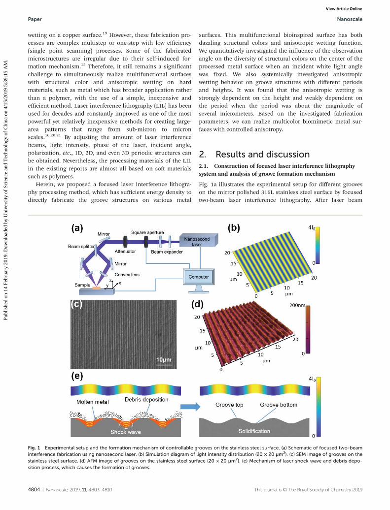
The grooves have similar optical properties to diffractiongratings due to their periodic structures. When white lightirradiates the grooves, the incident light is divided into spectrawith different wavelengths. The spectra are reflected differentlydue to the diffraction angle, which is dependent on the wave-length. This is why different structural colors can be observedat different observation angles when the sample is irradiatedby white light. Fig. 3a shows schematic of measuring theoptical properties of micro/nano grooves on the stainless steelsurface. The sample was vertically irradiated by white lightfrom a LED lamp. A digital optical camera that could move inthe plane vertical to the groove direction was used to capturethe reflected light at different angles. The angle between thedigital optical camera and the Z-axis is defined as the obser-vation angle α. In order to facilitate the study of the relationshipbetween structural color and observation angle α, groove struc-tural model is simplified and grooves are regarded as rectangu-lar reflection grating. Based on the model, a diffractionequation is deduced from the theoretical analysis to reveal therelationship between structural color and observation angle α:24
nλw ¼ dðsin αþ sin β sin γÞ; ð1Þwhere the integer n is the order of diffraction. λw is the wave-length of white light ranging from 400 nm to 700 nm, whichalmost covers visible color spectrum. d is the period of thegrooves (1450 nm). β is the angle between the white light andthe Z-axis. γ is the angle between the groove direction and theX-axis. In the experimental setup, both angle β and angle γ are
Nanoscale Paper
This journal is © The Royal Society of Chemistry 2019 Nanoscale, 2019, 11, 4803–4810 | 4805
Publ
ishe
d on
14
Febr
uary
201
9. D
ownl
oade
d by
Uni
vers
ity o
f Sc
ienc
e an
d T
echn
olog
y of
Chi
na o
n 4/
15/2
019
5:39
:15
AM
. View Article Online
designed to be 0 to reduce the difficulty of measurement andcalculation. Through calculation, when the angle α changesfrom 0 to 90°, only the first-order diffraction, second-orderdiffraction and partial third-order diffraction of the gratingcan be selected. To simplify the analysis, we ignored partialthird-order diffraction. Fig. 3b shows the curves of theoreticalcalculation of the wavelength of observed light at different α
angles and the corresponding color, when n = 1, 2, respect-ively. The experimental results agree well with the theoreticalcalculation curves. Fig. 3c–i and j–p show seven representativecolors of visible light and corresponding α angles, when n = 1,2, respectively. Due to the large size of the sample (6.5 ×
7 cm2), when the position of the optical camera is fixed, theobservation angles of the edge region and the central region ofthe sample are different, and this leads to a variety of struc-tural colors that can be seen at a certain α angle. Therefore,the central region of the sample is chosen as the object forstudying the structural color in the experiment. For example,in Fig. 3f when the observation angle α is 45.0°, the structuralcolor at the center of the sample is green. According to thecurves in Fig. 3b, the wavelength of light detected by theoptical camera should be 512.7 nm, which means the color isgreen at this observation angle. The actual observed structuralcolor is consistent with the theoretical calculation. Further,
Fig. 2 The relationship between groove height and laser fluence or number of laser shots. (a–c) AFM images and height curves of grooves whenlaser fluence is 0.215 J cm−2, 0.335 J cm−2, 0.404 J cm−2, respectively. (d) The curve of the relationship between groove height and laser fluence.(e–g) AFM images and height curves of grooves when number of laser shots is 30, 70, 130, respectively. (h) The curve of the relationship betweengroove height and number of laser shots.
Paper Nanoscale
4806 | Nanoscale, 2019, 11, 4803–4810 This journal is © The Royal Society of Chemistry 2019
Publ
ishe
d on
14
Febr
uary
201
9. D
ownl
oade
d by
Uni
vers
ity o
f Sc
ienc
e an
d T
echn
olog
y of
Chi
na o
n 4/
15/2
019
5:39
:15
AM
. View Article Online

comparing Fig. 3c–i with Fig. 3j–p, it can be clearly observedthat the structural color in Fig. 3j–p is brighter, which iscaused by the higher diffraction efficiency of the first-orderthan that of the second-order diffraction. In addition, itshould be noted that the existence of the observation anglecauses the rectangular sample to look trapezoidal in Fig. 3c–p.Fig. 3q shows other patterns (e.g., leaf, crab, windmill and soon) that can be processed by this focused laser interferencelithography system due to its excellent flexibility.
2.4. Anisotropic wetting under different heights and periodsof grooves
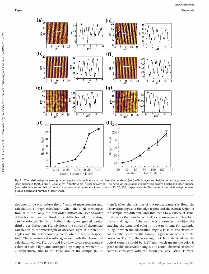
Another macroscopic function of this metal surface caused bythe microscopic grooves is the controlled anisotropic wetting.As seen in the sketch in Fig. 4a, the water droplet tends to flowparallel to the groove direction because it must overcome amuch higher energy barrier to flow vertical to rather than par-allel to the groove direction. Hence, when a series of differentsize droplets were dropped on the sample, they were all ovaland elongated in parallel with the direction of the groove(Fig. 4b). θ1 and θ2 were defined as the contact angles verticaland parallel to the groove direction, respectively. Δθ = θ1 − θ2
was defined to characterize the degree of wetting anisotropy.By adjusting the laser fluence and number of laser shots, theheight of the grooves was set to ∼200 nm, and four periods0.62 µm, 0.92 µm, 1.16 µm and 1.45 µm was obtained under θ= 16.67°, 11.10°, 8.83° and 7.04°, respectively. The Δθ angles ofthese four periods are all around 6°, which means no obviousdifference in anisotropic wetting behaviors. The reason may bethat the changes in the groove period are horizontal, and thehorizontal variations of the grooves do not obviously changethe energy barrier when it is less than 2 µm, which is consist-ent with the results reported by Mortia et al.25 By setting theincident angle θ to 7.04°, the period of the grooves was corre-spondingly determined to be 1.45 µm, and different grooveheights from 40 nm to 200 nm were obtained under differentnumber of laser shots. As shown in Fig. 4c, when the grooveheight increases, the angle θ1 increases from 83.0 ± 1.0° to86.9 ± 2.0°, while the angle θ2 remains ∼80°. This causes theangle Δθ to change from 3.1° to 6.1°, which means the aniso-tropic wetting increases as the groove height increases.Evidently, by changing the groove height, the degree of the an-isotropy of the metal surface can be precisely controlled. Inaddition, according to XPS analysis, the number of surface
Fig. 3 Experimental setup for measuring the optical properties. (a) Schematic of the way to characterize different structural colors of the stainlesssteel surface in different observation angles. (b) The theoretical curves and experimental points of the relationship between sample center color andobservation angle α when diffraction order n is 1, 2, respectively. (c–p) Multi-colors observed on the sample center displayed with different α angles.(q) Multi-patterns displayed with structural colors, such as leaf, crab, windmill and so on. Scale bars are 1 cm in (c–p), 5 mm in (q).
Nanoscale Paper
This journal is © The Royal Society of Chemistry 2019 Nanoscale, 2019, 11, 4803–4810 | 4807
Publ
ishe
d on
14
Febr
uary
201
9. D
ownl
oade
d by
Uni
vers
ity o
f Sc
ienc
e an
d T
echn
olog
y of
Chi
na o
n 4/
15/2
019
5:39
:15
AM
. View Article Online
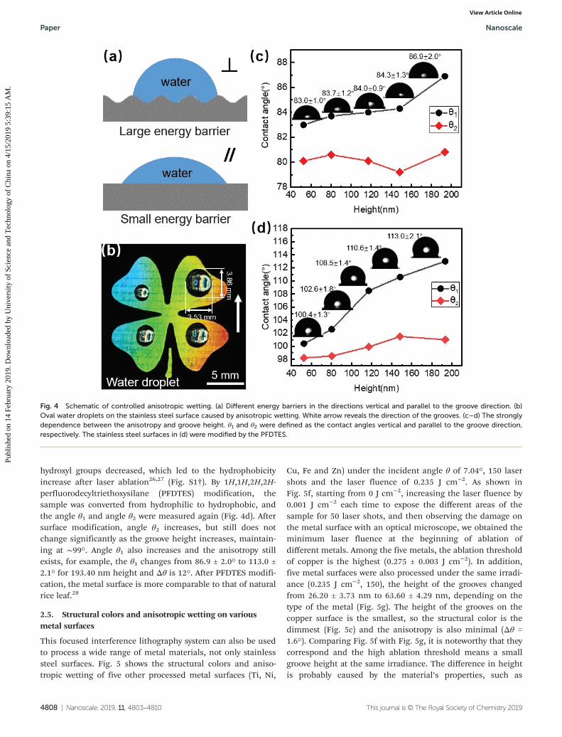
hydroxyl groups decreased, which led to the hydrophobicityincrease after laser ablation26,27 (Fig. S1†). By 1H,1H,2H,2H-perfluorodecyltriethoxysilane (PFDTES) modification, thesample was converted from hydrophilic to hydrophobic, andthe angle θ1 and angle θ2 were measured again (Fig. 4d). Aftersurface modification, angle θ2 increases, but still does notchange significantly as the groove height increases, maintain-ing at ∼99°. Angle θ1 also increases and the anisotropy stillexists, for example, the θ1 changes from 86.9 ± 2.0° to 113.0 ±2.1° for 193.40 nm height and Δθ is 12°. After PFDTES modifi-cation, the metal surface is more comparable to that of naturalrice leaf.28
2.5. Structural colors and anisotropic wetting on variousmetal surfaces
This focused interference lithography system can also be usedto process a wide range of metal materials, not only stainlesssteel surfaces. Fig. 5 shows the structural colors and aniso-tropic wetting of five other processed metal surfaces (Ti, Ni,
Cu, Fe and Zn) under the incident angle θ of 7.04°, 150 lasershots and the laser fluence of 0.235 J cm−2. As shown inFig. 5f, starting from 0 J cm−2, increasing the laser fluence by0.001 J cm−2 each time to expose the different areas of thesample for 50 laser shots, and then observing the damage onthe metal surface with an optical microscope, we obtained theminimum laser fluence at the beginning of ablation ofdifferent metals. Among the five metals, the ablation thresholdof copper is the highest (0.275 ± 0.003 J cm−2). In addition,five metal surfaces were also processed under the same irradi-ance (0.235 J cm−2, 150), the height of the grooves changedfrom 26.20 ± 3.73 nm to 63.60 ± 4.29 nm, depending on thetype of the metal (Fig. 5g). The height of the grooves on thecopper surface is the smallest, so the structural color is thedimmest (Fig. 5c) and the anisotropy is also minimal (Δθ =1.6°). Comparing Fig. 5f with Fig. 5g, it is noteworthy that theycorrespond and the high ablation threshold means a smallgroove height at the same irradiance. The difference in heightis probably caused by the material’s properties, such as
Fig. 4 Schematic of controlled anisotropic wetting. (a) Different energy barriers in the directions vertical and parallel to the groove direction. (b)Oval water droplets on the stainless steel surface caused by anisotropic wetting. White arrow reveals the direction of the grooves. (c–d) The stronglydependence between the anisotropy and groove height. θ1 and θ2 were defined as the contact angles vertical and parallel to the groove direction,respectively. The stainless steel surfaces in (d) were modified by the PFDTES.
Paper Nanoscale
4808 | Nanoscale, 2019, 11, 4803–4810 This journal is © The Royal Society of Chemistry 2019
Publ
ishe
d on
14
Febr
uary
201
9. D
ownl
oade
d by
Uni
vers
ity o
f Sc
ienc
e an
d T
echn
olog
y of
Chi
na o
n 4/
15/2
019
5:39
:15
AM
. View Article Online
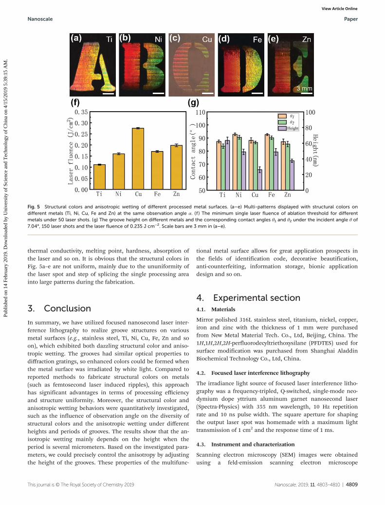
thermal conductivity, melting point, hardness, absorption ofthe laser and so on. It is obvious that the structural colors inFig. 5a–e are not uniform, mainly due to the ununiformity ofthe laser spot and step of splicing the single processing areainto large patterns during the fabrication.
3. Conclusion
In summary, we have utilized focused nanosecond laser inter-ference lithography to realize groove structures on variousmetal surfaces (e.g., stainless steel, Ti, Ni, Cu, Fe, Zn and soon), which exhibited both dazzling structural color and aniso-tropic wetting. The grooves had similar optical properties todiffraction gratings, so enhanced colors could be formed whenthe metal surface was irradiated by white light. Compared toreported methods to fabricate structural colors on metals(such as femtosecond laser induced ripples), this approachhas significant advantages in terms of processing efficiencyand structure uniformity. Moreover, the structural color andanisotropic wetting behaviors were quantitatively investigated,such as the influence of observation angle on the diversity ofstructural colors and the anisotropic wetting under differentheights and periods of grooves. The results show that the an-isotropic wetting mainly depends on the height when theperiod is several micrometers. Based on the investigated para-meters, we could precisely control the anisotropy by adjustingthe height of the grooves. These properties of the multifunc-
tional metal surface allows for great application prospects inthe fields of identification code, decorative beautification,anti-counterfeiting, information storage, bionic applicationdesign and so on.
4. Experimental section4.1. Materials
Mirror polished 316L stainless steel, titanium, nickel, copper,iron and zinc with the thickness of 1 mm were purchasedfrom New Metal Material Tech. Co., Ltd, Beijing, China. The1H,1H,2H,2H-perfluorodecyltriethoxysilane (PFDTES) used forsurface modification was purchased from Shanghai AladdinBiochemical Technology Co., Ltd, China.
4.2. Focused laser interference lithography
The irradiance light source of focused laser interference litho-graphy was a frequency-tripled, Q-switched, single-mode neo-dymium dope yttrium aluminum garnet nanosecond laser(Spectra-Physics) with 355 nm wavelength, 10 Hz repetitionrate and 10 ns pulse width. The square aperture for shapingthe output laser spot was homemade with a maximum lighttransmission of 1 cm2 and the response time of 1 ms.
4.3. Instrument and characterization
Scanning electron microscopy (SEM) images were obtainedusing a feld-emission scanning electron microscope
Fig. 5 Structural colors and anisotropic wetting of different processed metal surfaces. (a–e) Multi-patterns displayed with structural colors ondifferent metals (Ti, Ni, Cu, Fe and Zn) at the same observation angle α. (f ) The minimum single laser fluence of ablation threshold for differentmetals under 50 laser shots. (g) The groove height on different metals and the corresponding contact angles θ1 and θ2 under the incident angle θ of7.04°, 150 laser shots and the laser fluence of 0.235 J cm−2. Scale bars are 3 mm in (a–e).
Nanoscale Paper
This journal is © The Royal Society of Chemistry 2019 Nanoscale, 2019, 11, 4803–4810 | 4809
Publ
ishe
d on
14
Febr
uary
201
9. D
ownl
oade
d by
Uni
vers
ity o
f Sc
ienc
e an
d T
echn
olog
y of
Chi
na o
n 4/
15/2
019
5:39
:15
AM
. View Article Online
(JSM-6700F, JEOL, Tokyo, Japan). Atomic Force Microscope(AFM) worked in contact mode to measure the heights ofgrooves (MFP-3D-Origin, Oxford Instruments plc, Abingdon,UK). The contact angles of 5 µL water were measured by aContact Angle System CA100C (Shanghai Innuo precisioninstruments Co., Ltd, China). By measuring five drops atdifferent locations on the same surface at ambient tempera-ture, the average contact angles were obtained.
4.4. Quantitative measurement of structural color
The sample was irradiated vertically by white light from a cus-tomized LED lamp with the wavelength ranging from 400 nmto 700 nm. We built a rotating bracket so the digital opticalcamera (MV-SUA31GC-T, MindVision, Shenzhen, China) couldmove in the plane vertical to the groove direction and capturethe reflected light at different angles. In order to avoid disturb-ance from stray light from the surrounding environment, theexperiment was carried out in the dark.
4.5. Surface modification
After focused laser interference lithography, the sample wasimmersed in a 0.667% ethanol solution of PFDTES at ambienttemperature for 24 hours. The modified sample was sub-sequently dried on a hot plate at the temperature of 60 °C for25 minutes.
Author contributions
D. W. and J. W. L. participated in the design of this study, andthey both performed the statistical analysis. H. W. andY. L. J. conducted the experiments and prepared themanuscript. C. C. and S. W. Z. analyzed the XPS data in ESI.†C. C. Z., L. Y. and J. C. N. carried out literature search, C. Z. L.,Y. Y. Z. and S. J. J. carried out manuscript editing, Y. C. Z.,Y. L. H. and J. R. C. performed manuscript review.
Conflicts of interest
There are no conflicts to declare.
Acknowledgements
This work was supported by the National Key R&D Program ofChina (2017YFB1104303, 2018YFB1105400), the NationalNatural Science Foundation of China (No. 51805508,51675503, 51875544, 61805230, 51805509, 11801126),the Fundamental Research Funds for the Central Universities(WK2090090012, WK2480000002, WK2090090021,2192017bhzx0003), the China Postdoctoral Science Foundation(No. 2018M642534), and Youth Innovation PromotionAssociation CAS (2017495). We acknowledge the ExperimentalCenter of Engineering and Material Sciences, USTC.
References
1 D. Wu, J. N. Wang, S. Z. Wu, Q. D. Chen, S. Zhao, H. Zhang,H. B. Sun and L. Jiang, Adv. Funct. Mater., 2011, 21, 2927.
2 B. Bhushan and Y. C. J. Jung, Prog. Mater. Sci., 2011, 56, 1.3 J. W. Zhou, A. V. Ellis and N. H. Voelcker, Electrophoresis,
2010, 31, 2.4 D. Wu, Q. D. Chen, H. Xia, J. Jiao, B. B. Xu, X. F. Lin, Y. Xu
and H. B. Sun, Soft Matter, 2010, 6, 263.5 W. L. Min, B. Jiang and P. Jiang, Adv. Mater., 2008, 20, 3914.6 S. Kinoshita, S. Yoshioka and J. Miyazaki, Rep. Prog. Phys.,
2008, 71, 076401.7 G. Tayeb, B. Gralak and S. Enoch, Opt. Photonics News,
2003, 14, 38.8 Y. Zheng, X. Gao and L. Jiang, Soft Matter, 2007, 3, 178.9 H. M. Whitney, M. Kolle, P. Andrew, L. Chittka, U. Steiner
and B. J. Glover, Science, 2009, 323, 130.10 Y. Liu, X. Chen and J. H. Xin, Bioinspiration Biomimetics,
2008, 3, 046007.11 L. Feng, S. Li, Y. Li, H. Li, L. Zhang, J. Zhai, Y. Song, B. Liu,
L. Jiang and D. Zhu, Adv. Mater., 2002, 14, 1857.12 P. Ball, Nature, 1999, 400, 507.13 X. Wang, A. Kuchmizhak, D. Storozhenko, S. Makarov and
S. Juodkazis, ACS Appl. Mater. Interfaces, 2018, 10, 1422–1427.14 M. Xiao, Y. Li, M. C. Allen, D. D. Deheyn, X. Yue, J. Zhao,
N. C. Gianneschi, M. D. Shawkey and A. Dhinojwala, ACSNano, 2015, 9, 5454.
15 A. Y. Vorobyev and C. Guo, Appl. Phys. Lett., 2008, 92,041914.
16 M. I. Abid, L. Wang, Q.-D. Chen, X.-W. Wang, S. Juodkazisand H.-B. Sun, Laser Photonics Rev., 2017, 11, 1600187.
17 J. Yong, Q. Yang, F. Chen, D. Zhang, U. Farooq, G. Du andX. Hou, J. Mater. Chem. A, 2014, 2, 5499.
18 Z. Cheng, D. Zhang, T. Lv, H. Lai, E. Zhang, H. Kang,Y. Wang, P. Liu, Y. Liu, Y. Du and L. Jiang, Adv. Funct.Mater., 2018, 28, 1705002.
19 Y. Liu, S. Li, S. Niu, X. Cao, Z. Han and L. Ren, Appl. Surf.Sci., 2016, 379, 230.
20 A. Rodriguez, M. Echeverría, M. Ellman, N. Perez,Y. K. Verevkin, C. S. Peng, T. Berthou, Z. Wang, I. Ayerdi,J. Savall and S. M. Olaizola,Microelectron. Eng., 2009, 86, 937.
21 T. Kondo, S. Matsuo, S. Juodkazis and H. Misawa, Appl.Phys. Lett., 2001, 79, 725–727.
22 C. S. Montross, T. Wei, G. Clark and Y.-W. Mai,Int. J. Fatigue, 2002, 10, 1021–1036.
23 G. Li, J. Li, Y. Hu, C. Zhang, X. Li, J. Chu and W. Huang,Appl. Surf. Sci., 2014, 316, 451–455.
24 H. Lochbihler, Opt. Express, 2009, 17, 12189.25 M. Morita, T. Koga, H. Otsuka and A. Takahara, Langmuir,
2005, 21, 911.26 E. Velayi and R. Norouzbeigi, Appl. Surf. Sci., 2018, 441,
156–164.27 J. Long, M. Zhong, H. Zhang and P. Fan, J. Colloid Interface
Sci., 2015, 441, 1–9.28 S. G. Lee, H. S. Lim, D. Y. Lee, D. Kwak and K. Cho, Adv.
Funct. Mater., 2013, 23, 547–553.
Paper Nanoscale
4810 | Nanoscale, 2019, 11, 4803–4810 This journal is © The Royal Society of Chemistry 2019
Publ
ishe
d on
14
Febr
uary
201
9. D
ownl
oade
d by
Uni
vers
ity o
f Sc
ienc
e an
d T
echn
olog
y of
Chi
na o
n 4/
15/2
019
5:39
:15
AM
. View Article Online