Embed Size (px)
Citation preview
LARGE FLOATING DRY DOCKS
IN
THE UNITED STATES
Presented at:
DM CONSULTING
DRY DOCK CONFERENCE 2014
New Orleans, Louisiana
December 2014
Presented By:
Robert Heger
HEGER DRY DOCK, Inc.
531 Concord Street
Holliston, Massachusetts

Heger Dry Dock, Inc. LARGE FLOATING DOCKS IN THE UNITED STATES Page 0 December 2014
LARGE FLOATING DRY DOCKS
IN THE UNITED STATES Introduction Most of the larger shipyards in the United States employ floating dry docks to dry dock ships for repair or to launch newly constructed vessels. The dry docks come in all shapes and sizes and many have been designed specifically to serve certain types or classes of vessels or operate in a particular facility. Floating docks have a number of advantages: They can be built at the yard of the lowest bidder and towed to the site where it will be
used. This keeps initial construction costs lower by increasing competition among potential builders of the dock.
They can be re-sold on the world market and towed to a new location. This keeps resale value higher and makes it easier to get bank financing.
Vessels can be transferred to and from shore relatively easily.
The dock can be operated on a list or trim to a match a vessel with a list or trim at the time of docking or undocking. This feature can reduce block reactions and reduce or eliminate vessel stability problems when landing the vessel on the blocks.
The dock can be easily moved for dredging the sinking berth when required.
The dock can be moored such that it does not take up valuable waterfront real estate. Minimal landside civil works are required which can make permitting easier.
Vessels longer than the dock can be dry docked by overhanging the bow and or stern.
The dock can be moved away from land to deeper water for docking and undocking
operations. This can reduce or eliminate dredging and bulkheading requirements
A floating dock can be lengthened relatively easily. This paper provides brief descriptions of some of the larger floating dry docks located in the United States and highlights these advantages.
Heger Dry Dock, Inc. LARGE FLOATING DOCKS IN THE UNITED STATES Page 2 December 2014
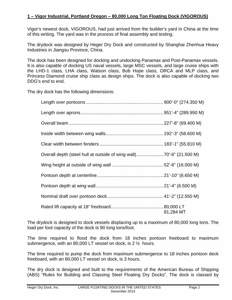
1 – Vigor Industrial, Portland Oregon – 80,000 Long Ton Floating Dock (VIGOROUS)
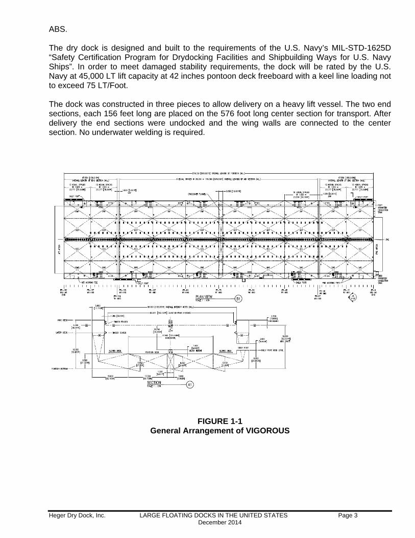
Vigor’s newest dock, VIGOROUS, had just arrived from the builder’s yard in China at the time of this writing. The yard was in the process of final assembly and testing. The drydock was designed by Heger Dry Dock and constructed by Shanghai Zhenhua Heavy Industries in Jiangsu Province, China. The dock has been designed for docking and undocking Panamax and Post-Panamax vessels. It is also capable of docking US naval vessels, large MSC vessels, and large cruise ships with the LHD-1 class, LHA class, Watson class, Bob Hope class, ORCA and MLP class, and Princess Diamond cruise ship class as design ships. The dock is also capable of docking two DDG’s end to end. The dry dock has the following dimensions:
Length over pontoons ............................................................. 900’-0” (274.350 M) Length over aprons ................................................................. 951’-4” (289.950 M) Overall beam .......................................................................... 227’-8” (69.400 M) Inside width between wing walls ............................................. 192’-3” (58.600 M)
Clear width between fenders .................................................. 183’-1” (55.810 M) Overall depth (steel hull at outside of wing wall) ..................... 70’-6” (21.500 M) Wing height at outside of wing wall ........................................ 52’-6” (16.000 M) Pontoon depth at centerline .................................................... 21’-10” (6.650 M) Pontoon depth at wing wall ..................................................... 21’-4” (6.500 M) Nominal draft over pontoon deck ............................................ 41’-2” (12.550 M) Rated lift capacity at 18” freeboard ......................................... 80,000 LT 81,284 MT
The drydock is designed to dock vessels displacing up to a maximum of 80,000 long tons. The load per foot capacity of the dock is 90 long tons/foot. The time required to flood the dock from 18 inches pontoon freeboard to maximum submergence, with an 80,000 LT vessel on dock, is 2 ½ hours. The time required to pump the dock from maximum submergence to 18 inches pontoon deck freeboard, with an 80,000 LT vessel on dock, is 3 hours. The dry dock is designed and built to the requirements of the American Bureau of Shipping (ABS) “Rules for Building and Classing Steel Floating Dry Docks”. The dock is classed by
Heger Dry Dock, Inc. LARGE FLOATING DOCKS IN THE UNITED STATES Page 3 December 2014
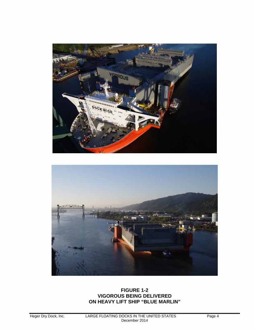
ABS. The dry dock is designed and built to the requirements of the U.S. Navy’s MIL-STD-1625D “Safety Certification Program for Drydocking Facilities and Shipbuilding Ways for U.S. Navy Ships”. In order to meet damaged stability requirements, the dock will be rated by the U.S. Navy at 45,000 LT lift capacity at 42 inches pontoon deck freeboard with a keel line loading not to exceed 75 LT/Foot. The dock was constructed in three pieces to allow delivery on a heavy lift vessel. The two end sections, each 156 feet long are placed on the 576 foot long center section for transport. After delivery the end sections were undocked and the wing walls are connected to the center section. No underwater welding is required.
FIGURE 1-1 General Arrangement of VIGOROUS
Heger Dry Dock, Inc. LARGE FLOATING DOCKS IN THE UNITED STATES Page 4 December 2014
FIGURE 1-2 VIGOROUS BEING DELIVERED
ON HEAVY LIFT SHIP “BLUE MARLIN”
Heger Dry Dock, Inc. LARGE FLOATING DOCKS IN THE UNITED STATES Page 5 December 2014
2 – BAE San Francisco – Dock No. 2
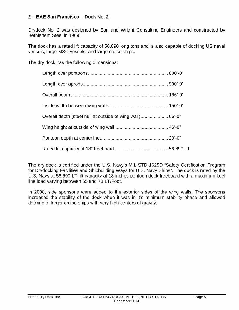
Drydock No. 2 was designed by Earl and Wright Consulting Engineers and constructed by Bethlehem Steel in 1969. The dock has a rated lift capacity of 56,690 long tons and is also capable of docking US naval vessels, large MSC vessels, and large cruise ships. The dry dock has the following dimensions:
Length over pontoons ............................................................. 800’-0” Length over aprons ................................................................. 900’-0” Overall beam .......................................................................... 186’-0” Inside width between wing walls ............................................. 150’-0”
Overall depth (steel hull at outside of wing wall) ..................... 66’-0” Wing height at outside of wing wall ........................................ 46’-0” Pontoon depth at centerline .................................................... 20’-0” Rated lift capacity at 18” freeboard ......................................... 56,690 LT
The dry dock is certified under the U.S. Navy’s MIL-STD-1625D “Safety Certification Program for Drydocking Facilities and Shipbuilding Ways for U.S. Navy Ships”. The dock is rated by the U.S. Navy at 56,690 LT lift capacity at 18 inches pontoon deck freeboard with a maximum keel line load varying between 65 and 73 LT/Foot. In 2008, side sponsons were added to the exterior sides of the wing walls. The sponsons increased the stability of the dock when it was in it’s minimum stability phase and allowed docking of larger cruise ships with very high centers of gravity.
Heger Dry Dock, Inc. LARGE FLOATING DOCKS IN THE UNITED STATES Page 6 December 2014
FIGURE 2-1 CRUISE SHIPS IN DD NO. 2
Heger Dry Dock, Inc. LARGE FLOATING DOCKS IN THE UNITED STATES Page 7 December 2014
3 – BAE San Diego – Dock No. 3 “Pride of San Diego”
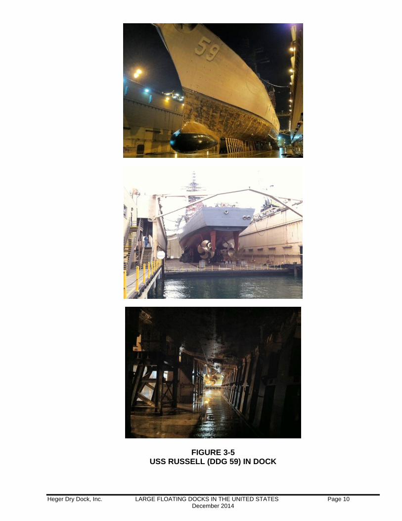
The “Pride of San Diego” was designed and constructed by Kawasaki Heavy Industries in 1984. The dock has a rated commercial lift capacity of 22,000 long tons and is capable of docking US naval cruisers, destroyers, the LCS class vessels, US Coast Guard vessels and medium size cruise ships. The dry dock has the following dimensions:
Length over pontoons ............................................................. 528’-3” Length over aprons ................................................................. 567’-7” Overall beam .......................................................................... 145’-0” Inside width between wing walls ............................................. 108’-11” Clear width between fenders .................................................. 106’-0”
Overall depth (steel hull at outside of wing wall) ..................... 74’-6” Wing height at outside of wing wall ........................................ 50’-6” Pontoon depth at centerline .................................................... 24’-5” Depth of water over keel blocks at max submergence ........... 39’-5” Rated lift capacity at 18” freeboard ......................................... 22,000 LT
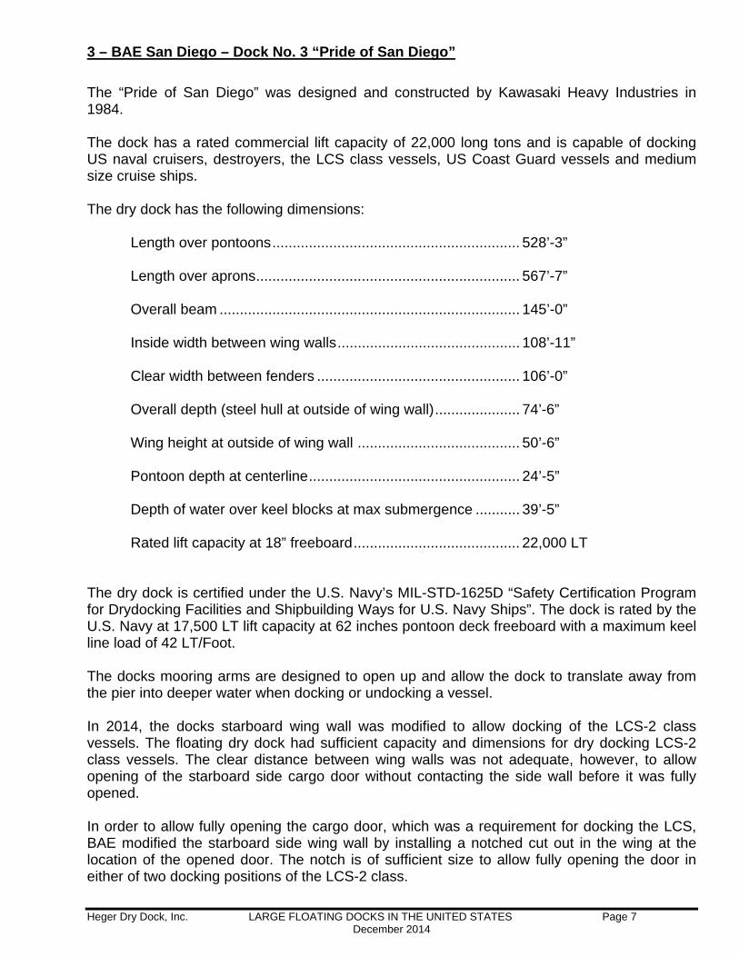
The dry dock is certified under the U.S. Navy’s MIL-STD-1625D “Safety Certification Program for Drydocking Facilities and Shipbuilding Ways for U.S. Navy Ships”. The dock is rated by the U.S. Navy at 17,500 LT lift capacity at 62 inches pontoon deck freeboard with a maximum keel line load of 42 LT/Foot. The docks mooring arms are designed to open up and allow the dock to translate away from the pier into deeper water when docking or undocking a vessel. In 2014, the docks starboard wing wall was modified to allow docking of the LCS-2 class vessels. The floating dry dock had sufficient capacity and dimensions for dry docking LCS-2 class vessels. The clear distance between wing walls was not adequate, however, to allow opening of the starboard side cargo door without contacting the side wall before it was fully opened. In order to allow fully opening the cargo door, which was a requirement for docking the LCS, BAE modified the starboard side wing wall by installing a notched cut out in the wing at the location of the opened door. The notch is of sufficient size to allow fully opening the door in either of two docking positions of the LCS-2 class.
Heger Dry Dock, Inc. LARGE FLOATING DOCKS IN THE UNITED STATES Page 8 December 2014
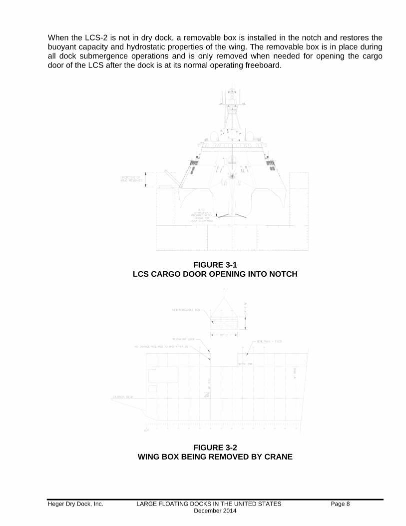
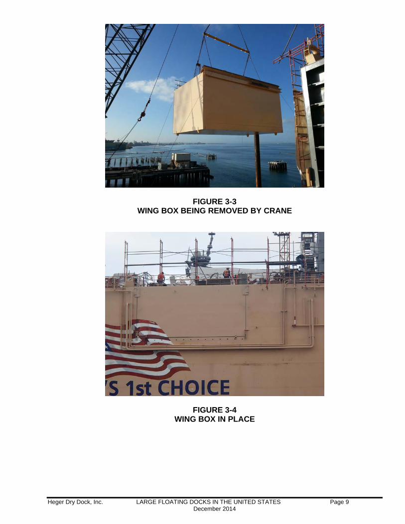
When the LCS-2 is not in dry dock, a removable box is installed in the notch and restores the buoyant capacity and hydrostatic properties of the wing. The removable box is in place during all dock submergence operations and is only removed when needed for opening the cargo door of the LCS after the dock is at its normal operating freeboard.
FIGURE 3-1
LCS CARGO DOOR OPENING INTO NOTCH
FIGURE 3-2 WING BOX BEING REMOVED BY CRANE
Heger Dry Dock, Inc. LARGE FLOATING DOCKS IN THE UNITED STATES Page 9 December 2014
FIGURE 3-3 WING BOX BEING REMOVED BY CRANE
FIGURE 3-4 WING BOX IN PLACE
Heger Dry Dock, Inc. LARGE FLOATING DOCKS IN THE UNITED STATES Page 10 December 2014
FIGURE 3-5 USS RUSSELL (DDG 59) IN DOCK
Heger Dry Dock, Inc. LARGE FLOATING DOCKS IN THE UNITED STATES Page 11 December 2014
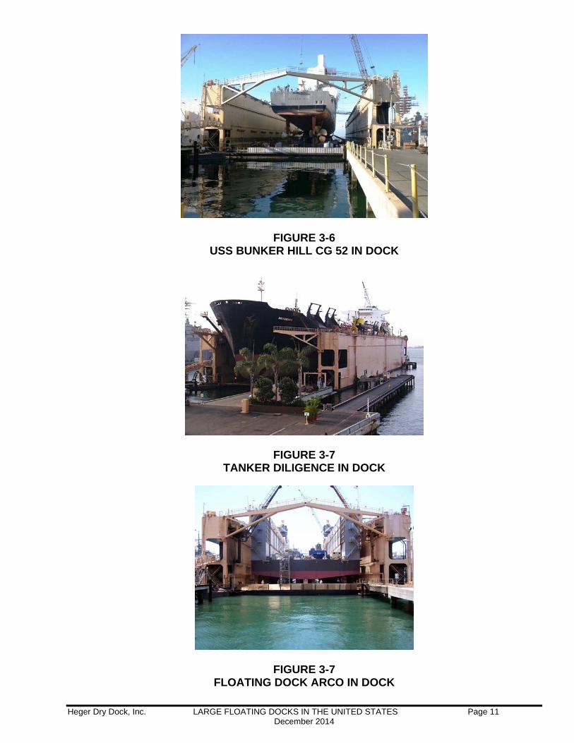
FIGURE 3-6 USS BUNKER HILL CG 52 IN DOCK
FIGURE 3-7 TANKER DILIGENCE IN DOCK
FIGURE 3-7 FLOATING DOCK ARCO IN DOCK
Heger Dry Dock, Inc. LARGE FLOATING DOCKS IN THE UNITED STATES Page 12 December 2014
4 – Keppel AMFELS, Brownsville, Texas – Floating Dock “Solomon P. Ortiz”
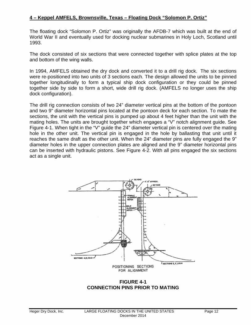
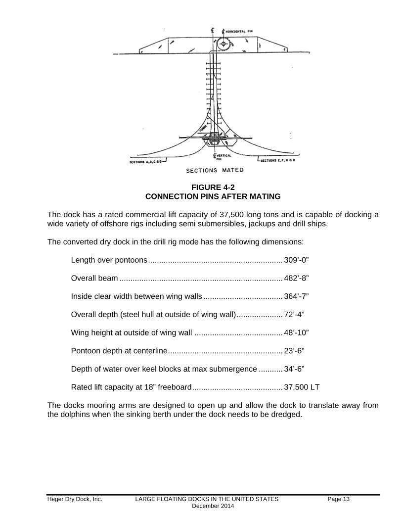
The floating dock “Solomon P. Ortiz” was originally the AFDB-7 which was built at the end of World War II and eventually used for docking nuclear submarines in Holy Loch, Scotland until 1993. The dock consisted of six sections that were connected together with splice plates at the top and bottom of the wing walls. In 1994, AMFELS obtained the dry dock and converted it to a drill rig dock. The six sections were re-positioned into two units of 3 sections each. The design allowed the units to be pinned together longitudinally to form a typical ship dock configuration or they could be pinned together side by side to form a short, wide drill rig dock. (AMFELS no longer uses the ship dock configuration). The drill rig connection consists of two 24” diameter vertical pins at the bottom of the pontoon and two 9” diameter horizontal pins located at the pontoon deck for each section. To mate the sections, the unit with the vertical pins is pumped up about 4 feet higher than the unit with the mating holes. The units are brought together which engages a “V” notch alignment guide. See Figure 4-1. When tight in the “V” guide the 24” diameter vertical pin is centered over the mating hole in the other unit. The vertical pin is engaged in the hole by ballasting that unit until it reaches the same draft as the other unit. When the 24” diameter pins are fully engaged the 9” diameter holes in the upper connection plates are aligned and the 9” diameter horizontal pins can be inserted with hydraulic pistons. See Figure 4-2. With all pins engaged the six sections act as a single unit.
FIGURE 4-1 CONNECTION PINS PRIOR TO MATING
Heger Dry Dock, Inc. LARGE FLOATING DOCKS IN THE UNITED STATES Page 13 December 2014
FIGURE 4-2 CONNECTION PINS AFTER MATING
The dock has a rated commercial lift capacity of 37,500 long tons and is capable of docking a wide variety of offshore rigs including semi submersibles, jackups and drill ships. The converted dry dock in the drill rig mode has the following dimensions:
Length over pontoons ............................................................. 309’-0” Overall beam .......................................................................... 482’-8” Inside clear width between wing walls .................................... 364’-7”
Overall depth (steel hull at outside of wing wall) ..................... 72’-4” Wing height at outside of wing wall ........................................ 48’-10” Pontoon depth at centerline .................................................... 23’-6” Depth of water over keel blocks at max submergence ........... 34’-6” Rated lift capacity at 18” freeboard ......................................... 37,500 LT
The docks mooring arms are designed to open up and allow the dock to translate away from the dolphins when the sinking berth under the dock needs to be dredged.
Heger Dry Dock, Inc. LARGE FLOATING DOCKS IN THE UNITED STATES Page 14 December 2014
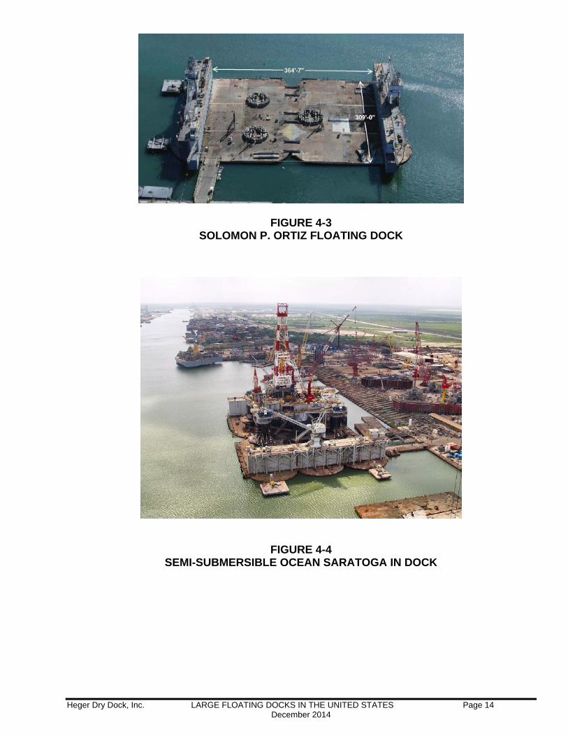
FIGURE 4-3 SOLOMON P. ORTIZ FLOATING DOCK
FIGURE 4-4
SEMI-SUBMERSIBLE OCEAN SARATOGA IN DOCK
Heger Dry Dock, Inc. LARGE FLOATING DOCKS IN THE UNITED STATES Page 15 December 2014
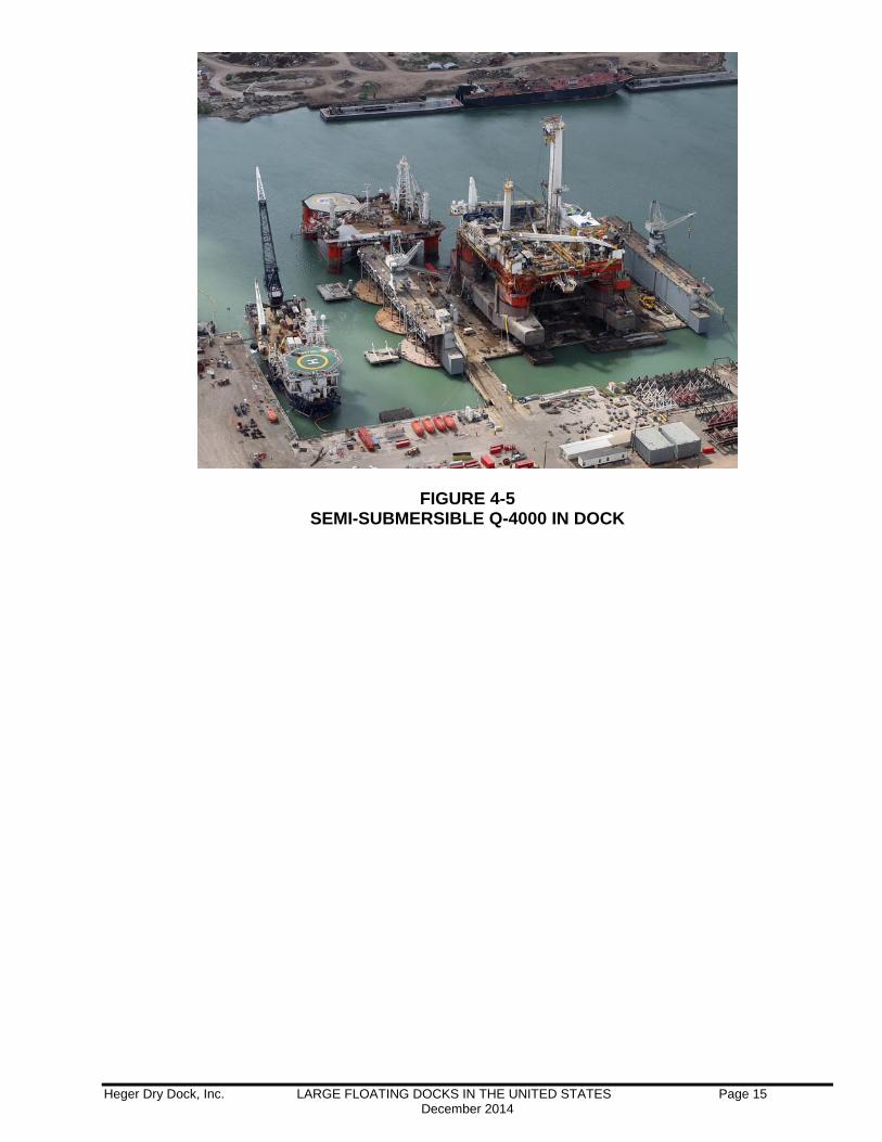
FIGURE 4-5 SEMI-SUBMERSIBLE Q-4000 IN DOCK
Heger Dry Dock, Inc. LARGE FLOATING DOCKS IN THE UNITED STATES Page 16 December 2014
5 – BAE Southeast, Mobile, Alabama – Floating Dock “ALABAMA”
The “ALABAMA” was designed and constructed by Kawasaki Heavy Industries in 1982. It was originally delivered to Todd Shipyard Corporation’s Galveston, Texas yard. In 1991 the dock was relocated to Atlantic Marine’s Yard on Pinto Island in Mobile, Alabama. Later Atlantic Marine was acquired by BAE, Southeast Shipyards. The dock has a rated commercial lift capacity of 46,400 long tons and is capable of docking commercial ships, MSC vessels, drill ships and cruise ships. The dry dock has the following dimensions:
Length over pontoons ............................................................. 787’-4” Length over aprons ................................................................. 853’-0” Overall beam .......................................................................... 200’-0” Inside width between wing walls ............................................. 173’-10” Clear width between fenders .................................................. 164’-0”
Overall depth (steel hull at outside of wing wall) ..................... 68’-10” Wing height at outside of wing wall ........................................ 51’-4” Pontoon depth at centerline .................................................... 18’-4” Depth of water over keel blocks at max submergence ........... 32’-0” Rated lift capacity at 18” freeboard ......................................... 46,400 LT
The dry dock is commercially certified by Heger Dry Dock for 46,400 LT lift capacity at 18 inches pontoon deck freeboard with a maximum keel line load of 63.5 LT/Foot.
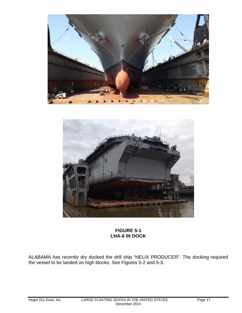
Although not certified by the US Navy, BAE recently obtained a one-time certification to dry dock the USS AMERICA (LHA 6). See Figure 5-1
Heger Dry Dock, Inc. LARGE FLOATING DOCKS IN THE UNITED STATES Page 17 December 2014
FIGURE 5-1
LHA-6 IN DOCK
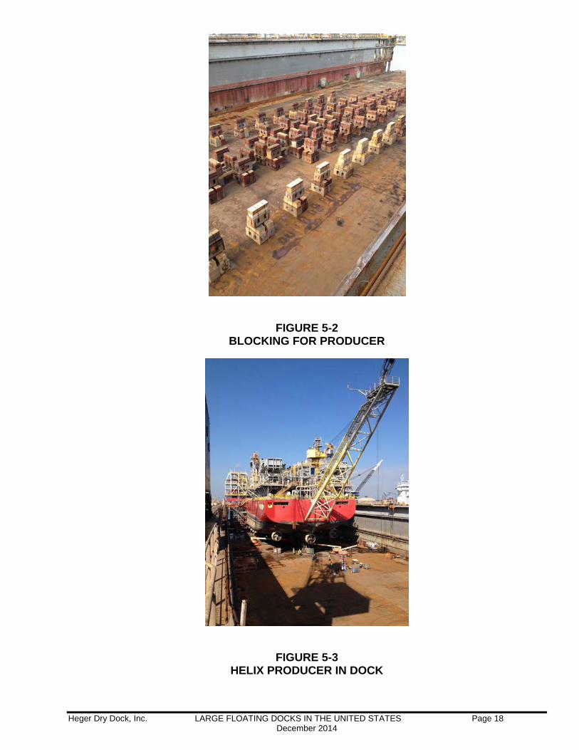
ALABAMA has recently dry docked the drill ship “HELIX PRODUCER”. The docking required the vessel to be landed on high blocks. See Figures 5-2 and 5-3.
Heger Dry Dock, Inc. LARGE FLOATING DOCKS IN THE UNITED STATES Page 18 December 2014
FIGURE 5-2
BLOCKING FOR PRODUCER
FIGURE 5-3
HELIX PRODUCER IN DOCK
Heger Dry Dock, Inc. LARGE FLOATING DOCKS IN THE UNITED STATES Page 19 December 2014
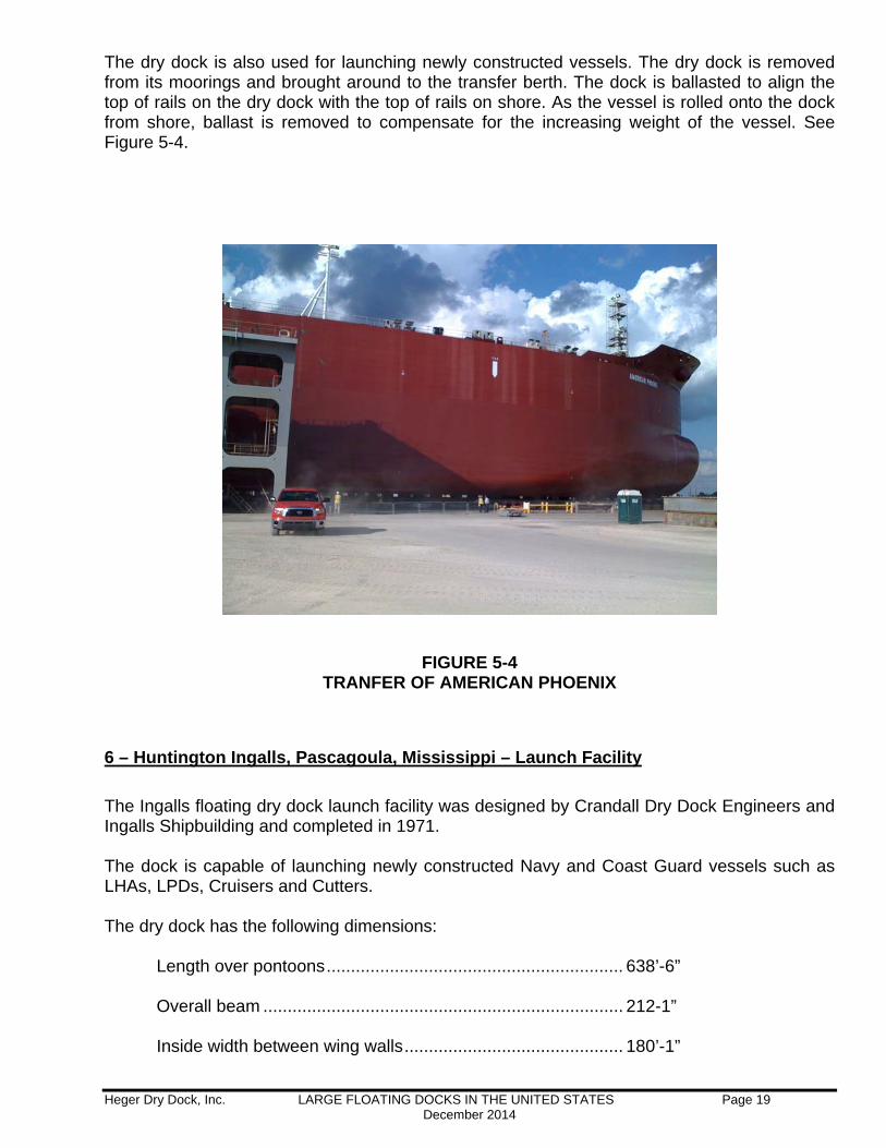
The dry dock is also used for launching newly constructed vessels. The dry dock is removed from its moorings and brought around to the transfer berth. The dock is ballasted to align the top of rails on the dry dock with the top of rails on shore. As the vessel is rolled onto the dock from shore, ballast is removed to compensate for the increasing weight of the vessel. See Figure 5-4.
FIGURE 5-4
TRANFER OF AMERICAN PHOENIX
6 – Huntington Ingalls, Pascagoula, Mississippi – Launch Facility
The Ingalls floating dry dock launch facility was designed by Crandall Dry Dock Engineers and Ingalls Shipbuilding and completed in 1971. The dock is capable of launching newly constructed Navy and Coast Guard vessels such as LHAs, LPDs, Cruisers and Cutters. The dry dock has the following dimensions:
Length over pontoons ............................................................. 638’-6” Overall beam .......................................................................... 212-1” Inside width between wing walls ............................................. 180’-1”
Heger Dry Dock, Inc. LARGE FLOATING DOCKS IN THE UNITED STATES Page 20 December 2014
Clear width between fenders .................................................. 177’-3”
Overall depth (steel hull at outside of wing wall) ..................... 69’-9” Wing height at outside of wing wall ........................................ 46’-0” Pontoon depth at centerline .................................................... 24’-3” Depth of water over keel blocks at max submergence ........... 35’-0” Rated lift capacity ................................................................... 57,000 LT Rated Transfer Capacity ......................................................... 35,000 LT
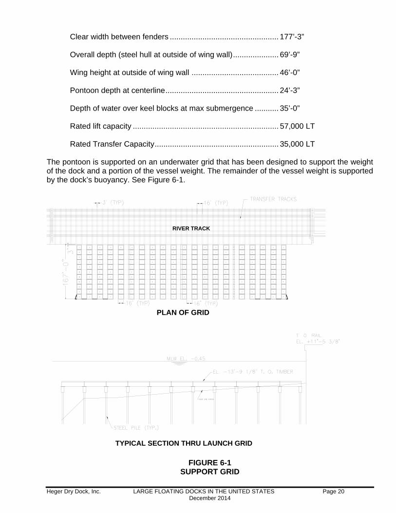
The pontoon is supported on an underwater grid that has been designed to support the weight of the dock and a portion of the vessel weight. The remainder of the vessel weight is supported by the dock’s buoyancy. See Figure 6-1.
PLAN OF GRID
RIVER TRACK
TYPICAL SECTION THRU LAUNCH GRID
FIGURE 6-1 SUPPORT GRID

Heger Dry Dock, Inc. LARGE FLOATING DOCKS IN THE UNITED STATES Page 21 December 2014
Ships are moved onto the dock transversely from shore. In order to prepare for transfer, the starboard side wing wall must be removed. The starboard wing wall is constructed of 80 foot long boxes that can be unpinned and lifted off by crane. Figure 6-2 shows a wing box being lifted by shore side cranes.
FIGURE 6-2 WING REMOVAL
Buoyancy is used to offset a portion of the vessel weight during transfer. Ballast is added or removed as needed to partially compensate for the vessel weight coming on to the dock
FIGURE 6-3
BALLAST SEQUENCE
Heger Dry Dock, Inc. LARGE FLOATING DOCKS IN THE UNITED STATES Page 22 December 2014
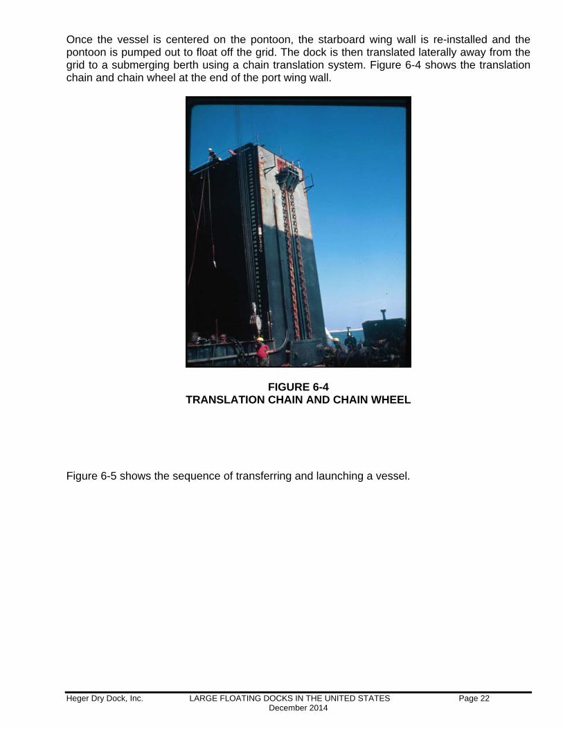
Once the vessel is centered on the pontoon, the starboard wing wall is re-installed and the pontoon is pumped out to float off the grid. The dock is then translated laterally away from the grid to a submerging berth using a chain translation system. Figure 6-4 shows the translation chain and chain wheel at the end of the port wing wall.
FIGURE 6-4 TRANSLATION CHAIN AND CHAIN WHEEL
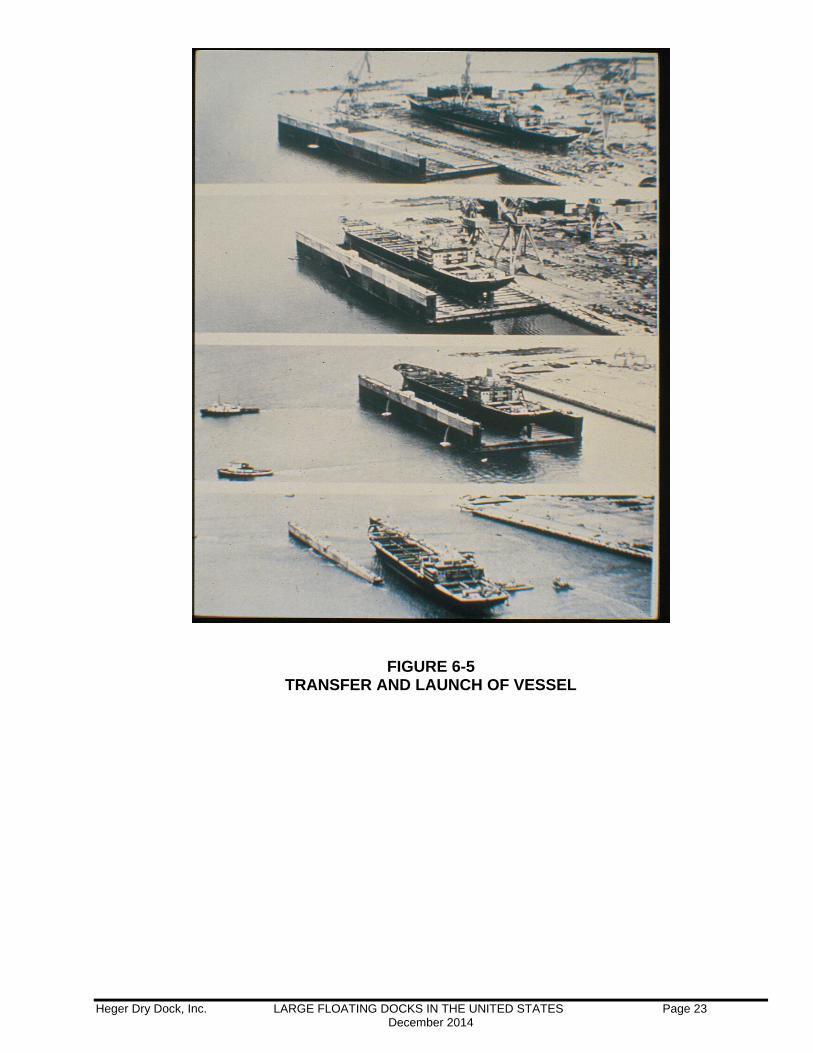
Figure 6-5 shows the sequence of transferring and launching a vessel.
Heger Dry Dock, Inc. LARGE FLOATING DOCKS IN THE UNITED STATES Page 23 December 2014
FIGURE 6-5
TRANSFER AND LAUNCH OF VESSEL
Heger Dry Dock, Inc. LARGE FLOATING DOCKS IN THE UNITED STATES Page 24 December 2014
7 – BAE, Norfolk, Virginia – Floating Dock “TITAN”
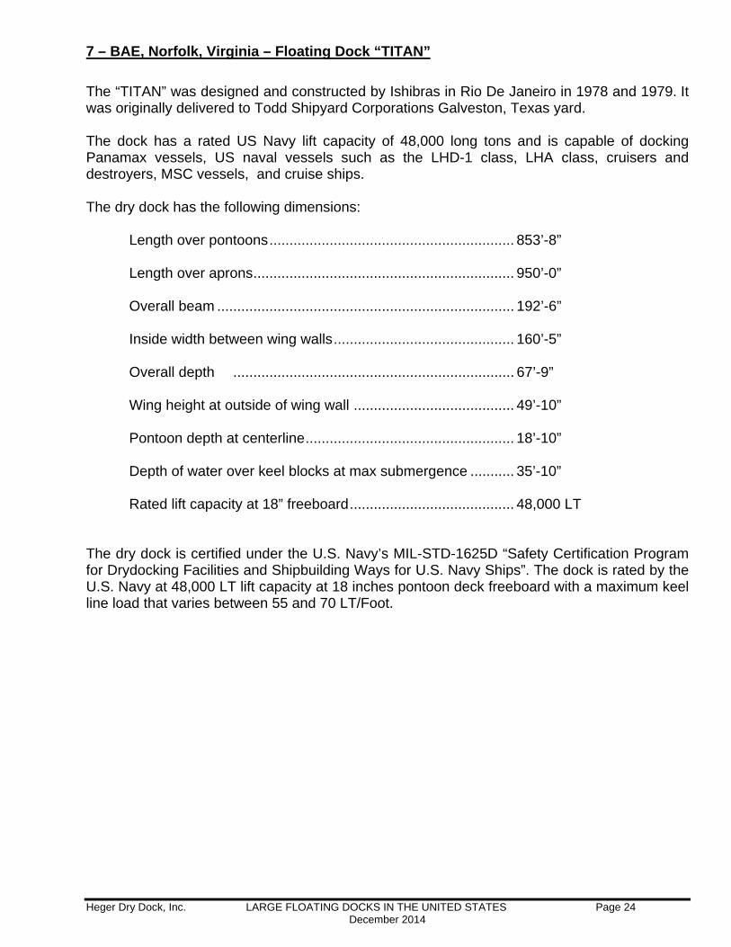
The “TITAN” was designed and constructed by Ishibras in Rio De Janeiro in 1978 and 1979. It was originally delivered to Todd Shipyard Corporations Galveston, Texas yard. The dock has a rated US Navy lift capacity of 48,000 long tons and is capable of docking Panamax vessels, US naval vessels such as the LHD-1 class, LHA class, cruisers and destroyers, MSC vessels, and cruise ships. The dry dock has the following dimensions:
Length over pontoons ............................................................. 853’-8” Length over aprons ................................................................. 950’-0” Overall beam .......................................................................... 192’-6” Inside width between wing walls ............................................. 160’-5”
Overall depth ...................................................................... 67’-9” Wing height at outside of wing wall ........................................ 49’-10” Pontoon depth at centerline .................................................... 18’-10” Depth of water over keel blocks at max submergence ........... 35’-10” Rated lift capacity at 18” freeboard ......................................... 48,000 LT
The dry dock is certified under the U.S. Navy’s MIL-STD-1625D “Safety Certification Program for Drydocking Facilities and Shipbuilding Ways for U.S. Navy Ships”. The dock is rated by the U.S. Navy at 48,000 LT lift capacity at 18 inches pontoon deck freeboard with a maximum keel line load that varies between 55 and 70 LT/Foot.

Heger Dry Dock, Inc. LARGE FLOATING DOCKS IN THE UNITED STATES Page 25 December 2014
FIGURE 7-1 CRUISE SHIP ON TITAN
FIGURE 7-2
MSC SHIP ON TITAN
Heger Dry Dock, Inc. LARGE FLOATING DOCKS IN THE UNITED STATES Page 26 December 2014
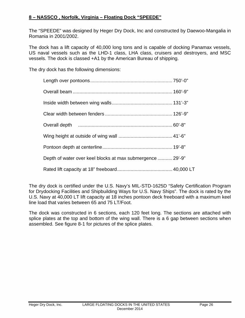
8 – NASSCO , Norfolk, Virginia – Floating Dock “SPEEDE”
The “SPEEDE” was designed by Heger Dry Dock, Inc and constructed by Daewoo-Mangalia in Romania in 2001/2002. The dock has a lift capacity of 40,000 long tons and is capable of docking Panamax vessels, US naval vessels such as the LHD-1 class, LHA class, cruisers and destroyers, and MSC vessels. The dock is classed +A1 by the American Bureau of shipping. The dry dock has the following dimensions:
Length over pontoons ............................................................. 750’-0” Overall beam .......................................................................... 160’-9” Inside width between wing walls ............................................. 131’-3” Clear width between fenders .................................................. 126’-9”
Overall depth ...................................................................... 60’-8” Wing height at outside of wing wall ........................................ 41’-6” Pontoon depth at centerline .................................................... 19’-8” Depth of water over keel blocks at max submergence ........... 29’-9” Rated lift capacity at 18” freeboard ......................................... 40,000 LT
The dry dock is certified under the U.S. Navy’s MIL-STD-1625D “Safety Certification Program for Drydocking Facilities and Shipbuilding Ways for U.S. Navy Ships”. The dock is rated by the U.S. Navy at 40,000 LT lift capacity at 18 inches pontoon deck freeboard with a maximum keel line load that varies between 65 and 75 LT/Foot.
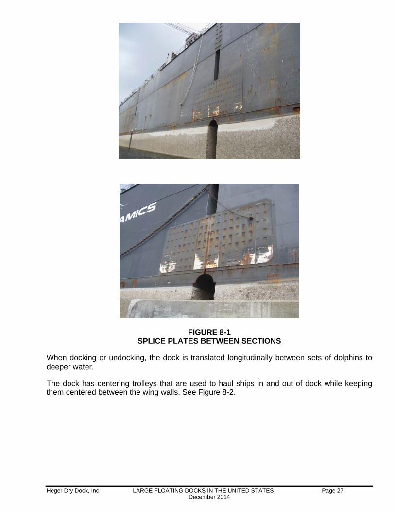
The dock was constructed in 6 sections, each 120 feet long. The sections are attached with splice plates at the top and bottom of the wing wall. There is a 6 gap between sections when assembled. See figure 8-1 for pictures of the splice plates.
Heger Dry Dock, Inc. LARGE FLOATING DOCKS IN THE UNITED STATES Page 27 December 2014
FIGURE 8-1 SPLICE PLATES BETWEEN SECTIONS
When docking or undocking, the dock is translated longitudinally between sets of dolphins to deeper water.
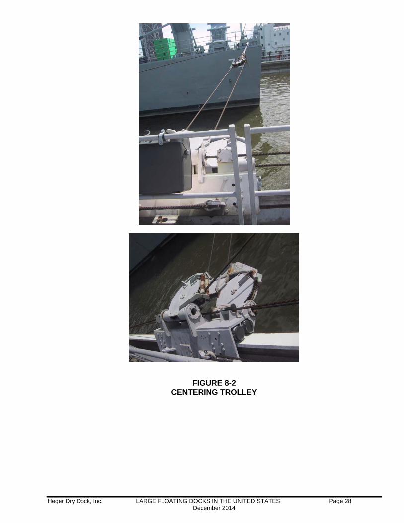
The dock has centering trolleys that are used to haul ships in and out of dock while keeping them centered between the wing walls. See Figure 8-2.
Heger Dry Dock, Inc. LARGE FLOATING DOCKS IN THE UNITED STATES Page 28 December 2014
FIGURE 8-2
CENTERING TROLLEY
Heger Dry Dock, Inc. LARGE FLOATING DOCKS IN THE UNITED STATES Page 29 December 2014
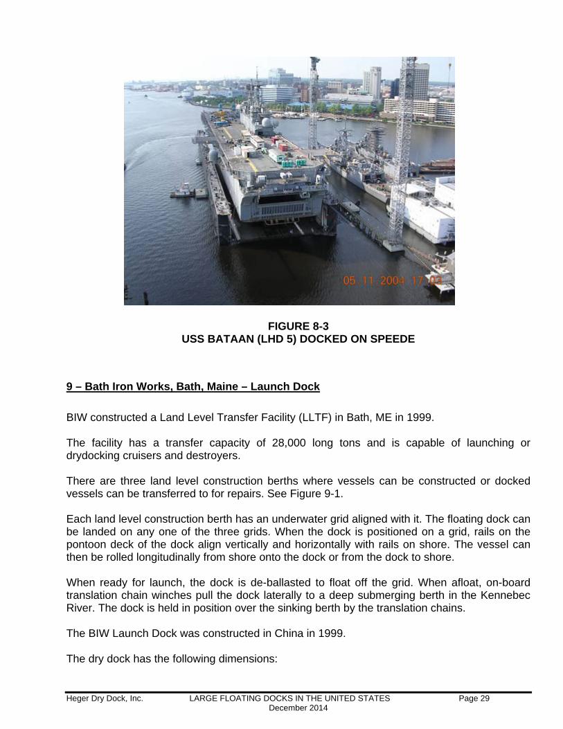
FIGURE 8-3 USS BATAAN (LHD 5) DOCKED ON SPEEDE
9 – Bath Iron Works, Bath, Maine – Launch Dock
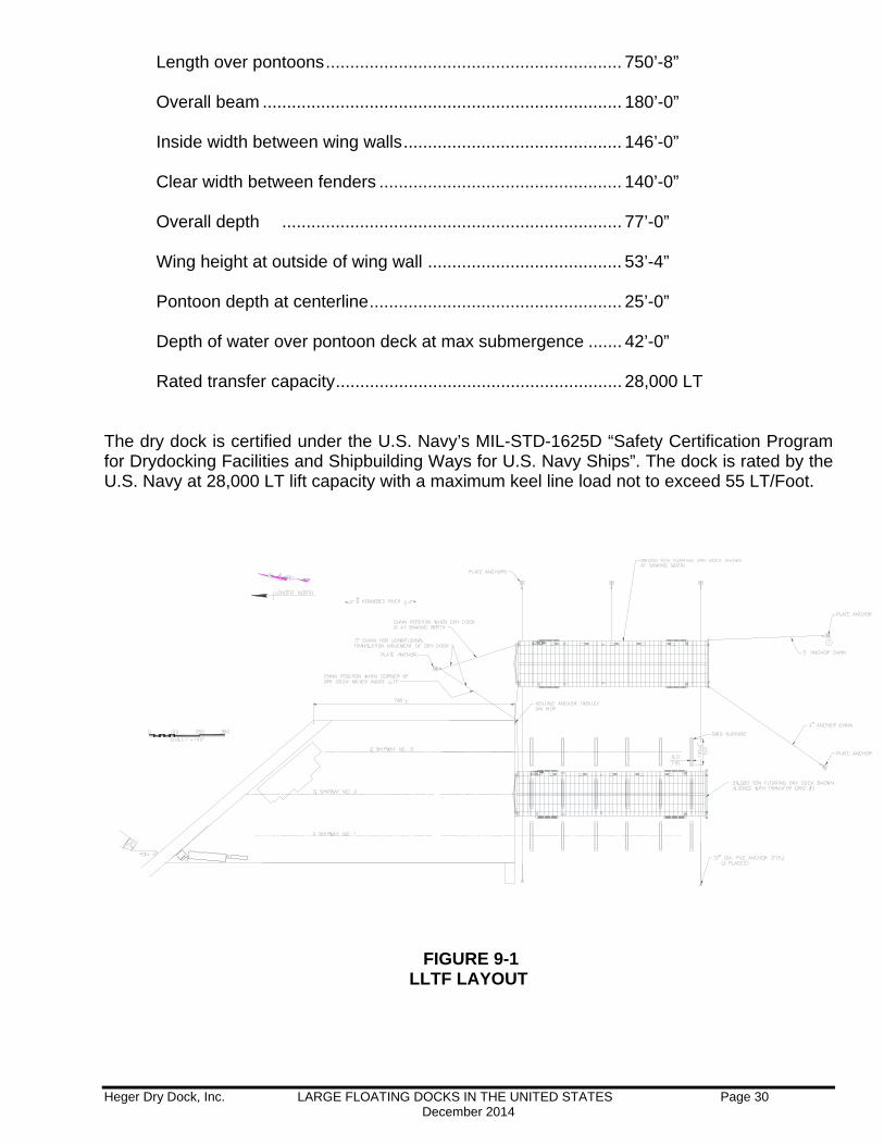
BIW constructed a Land Level Transfer Facility (LLTF) in Bath, ME in 1999. The facility has a transfer capacity of 28,000 long tons and is capable of launching or drydocking cruisers and destroyers. There are three land level construction berths where vessels can be constructed or docked vessels can be transferred to for repairs. See Figure 9-1. Each land level construction berth has an underwater grid aligned with it. The floating dock can be landed on any one of the three grids. When the dock is positioned on a grid, rails on the pontoon deck of the dock align vertically and horizontally with rails on shore. The vessel can then be rolled longitudinally from shore onto the dock or from the dock to shore. When ready for launch, the dock is de-ballasted to float off the grid. When afloat, on-board translation chain winches pull the dock laterally to a deep submerging berth in the Kennebec River. The dock is held in position over the sinking berth by the translation chains. The BIW Launch Dock was constructed in China in 1999. The dry dock has the following dimensions:
Heger Dry Dock, Inc. LARGE FLOATING DOCKS IN THE UNITED STATES Page 30 December 2014
Length over pontoons ............................................................. 750’-8” Overall beam .......................................................................... 180’-0” Inside width between wing walls ............................................. 146’-0” Clear width between fenders .................................................. 140’-0”
Overall depth ...................................................................... 77’-0” Wing height at outside of wing wall ........................................ 53’-4” Pontoon depth at centerline .................................................... 25’-0” Depth of water over pontoon deck at max submergence ....... 42’-0” Rated transfer capacity ........................................................... 28,000 LT
The dry dock is certified under the U.S. Navy’s MIL-STD-1625D “Safety Certification Program for Drydocking Facilities and Shipbuilding Ways for U.S. Navy Ships”. The dock is rated by the U.S. Navy at 28,000 LT lift capacity with a maximum keel line load not to exceed 55 LT/Foot.
FIGURE 9-1 LLTF LAYOUT
Heger Dry Dock, Inc. LARGE FLOATING DOCKS IN THE UNITED STATES Page 31 December 2014
The underwater grid has been designed to support the weight of the dock and the full weight of the vessel. Once on the grid, ballast tank flood valves are left open such that the tanks free flood and drain as the tide fluctuates. In this way no active ballasting needs to occur until ready to move the dock off the grid.
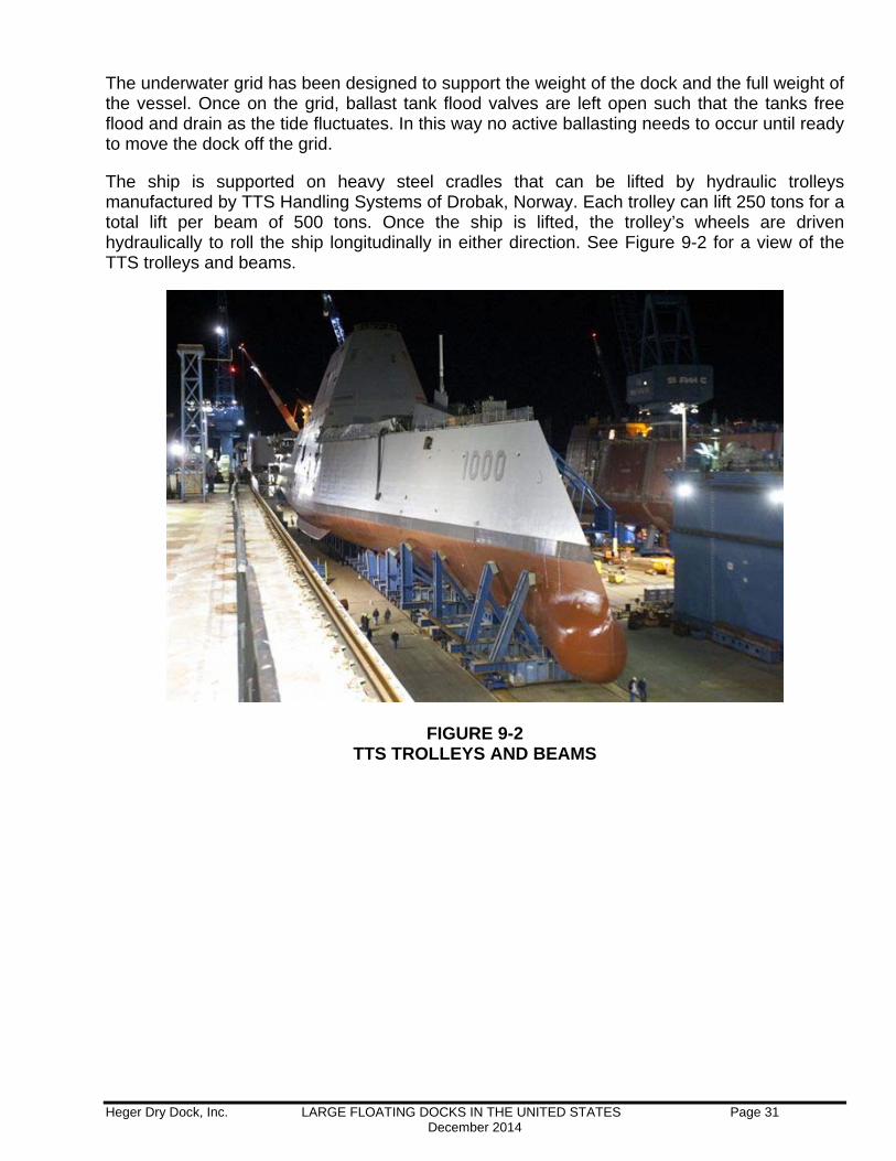
The ship is supported on heavy steel cradles that can be lifted by hydraulic trolleys manufactured by TTS Handling Systems of Drobak, Norway. Each trolley can lift 250 tons for a total lift per beam of 500 tons. Once the ship is lifted, the trolley’s wheels are driven hydraulically to roll the ship longitudinally in either direction. See Figure 9-2 for a view of the TTS trolleys and beams.
FIGURE 9-2 TTS TROLLEYS AND BEAMS
Heger Dry Dock, Inc. LARGE FLOATING DOCKS IN THE UNITED STATES Page 32 December 2014
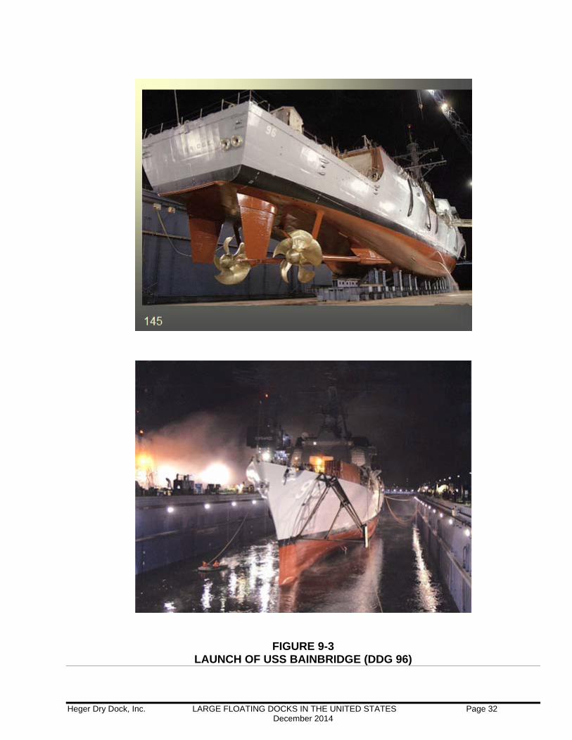
FIGURE 9-3 LAUNCH OF USS BAINBRIDGE (DDG 96)
Heger Dry Dock, Inc. LARGE FLOATING DOCKS IN THE UNITED STATES Page 33 December 2014
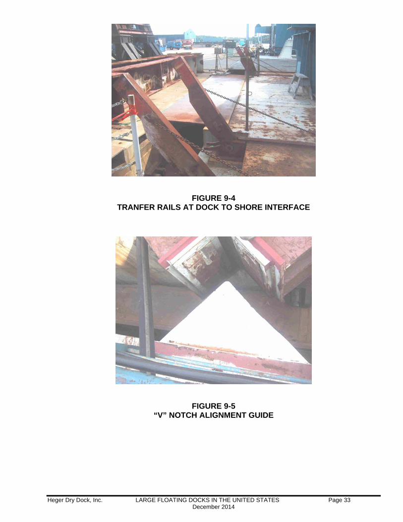
FIGURE 9-4
TRANFER RAILS AT DOCK TO SHORE INTERFACE
FIGURE 9-5
“V” NOTCH ALIGNMENT GUIDE
Heger Dry Dock, Inc. LARGE FLOATING DOCKS IN THE UNITED STATES Page 34 December 2014
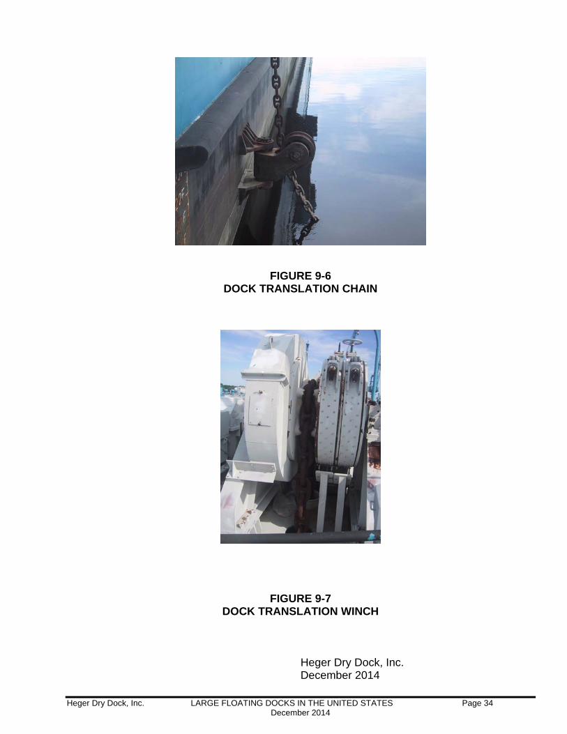
FIGURE 9-6
DOCK TRANSLATION CHAIN
FIGURE 9-7
DOCK TRANSLATION WINCH Heger Dry Dock, Inc. December 2014
![5 – BINÄRE ENTSCHEIDUNGS- DIAGRAMME (BDDS) · BDD-Varianten (I) 08.06.2009 23 FDDs: [Kebschull, Schubert, Rosenstiel; 1992] Functional Decision Diagrams (Positive) Davio-Expansion](https://img.pdfslide.net/doc/110x75/5f073c927e708231d41bfd31/5-a-binre-entscheidungs-diagramme-bdds-bdd-varianten-i-08062009-23-fdds.jpg)