Embed Size (px)
Citation preview

Universitat de Lleida Escola Politècnica Superior Grau d’Enginyeria Mecànica
Projecte Final de Grau
LARGE-SCALE UNDERGROUND THERMAL ENERGY STORAGE
-Using industrial waste heat to supply district heating-
Autor: Jordi Jové Manonelles Directora: Dra. Luisa F. Cabeza
Juliol 2014

Large-scale Underground Thermal Energy Storage:
Using industrial waste heat to supply District Heating
Jordi Jové Manonelles
- 1 -

Large-scale Underground Thermal Energy Storage:
Using industrial waste heat to supply District Heating
Jordi Jové Manonelles
- 2 -
ACKNOWLEDGMENTS
I would like to thank Professor Bo Nordell from Luleå University of Technology for his help and his
support throughout the project. I would also like to acknowledge Kjell Skogsberg from Snowpower,
who gave me the opportunity to work on this project and also has been a great support and help
during the project with data and advices.

Large-scale Underground Thermal Energy Storage:
Using industrial waste heat to supply District Heating
Jordi Jové Manonelles
- 3 -
0 Table of contents
0 TABLE OF CONTENTS ............................................................................................................................ - 3 -
List of Notations ......................................................................................................................................... - 6 -
List of Tables ............................................................................................................................................... - 7 -
List of figures .............................................................................................................................................. - 9 -
1 INTRODUCTION.................................................................................................................................. - 11 -
1.1 ABSTRACT ............................................................................................................................................- 11 -
1.2 OBJECTIVE ............................................................................................................................................- 11 -
2 BACKGROUND ................................................................................................................................... - 12 -
2.1 ENERGY CONSUMPTION ..........................................................................................................................- 12 -
2.2 ENERGY COST ........................................................................................................................................- 13 -
2.3 WASTE ENERGY .....................................................................................................................................- 13 -
2.4 ENERGY STORAGE (ES) ...........................................................................................................................- 14 -
3 THERMAL ENERGY STORAGE (TES) ..................................................................................................... - 16 -
3.1.1 Barriers to TES ............................................................................................................................. - 17 -
3.2 UNDERGROUND THERMAL ENERGY STORAGE (UTES) ..................................................................................- 17 -
3.2.1 Application of UTES ..................................................................................................................... - 17 -
3.3 ROCK CAVERN THERMAL ENERGY STORAGE (CTES) .....................................................................................- 18 -
3.4 AQUIFER THERMAL ENERGY STORAGE (ATES) ............................................................................................- 19 -
3.5 BOREHOLE THERMAL ENERGY STORAGE (BTES) ..........................................................................................- 20 -
3.5.1 Applications ................................................................................................................................. - 21 -
4 BTES. SYSTEM DESCRIPTION .............................................................................................................. - 23 -
4.1 GROUND THERMAL PROPERTIES ................................................................................................................- 23 -
4.1.1 Thermal conductivity ................................................................................................................... - 23 -
4.1.2 Volumetric heat capacity ............................................................................................................. - 23 -
4.1.3 Geothermal Gradient .................................................................................................................. - 23 -
4.2 HEAT CARRIER FLUID ..............................................................................................................................- 24 -
4.3 FILLING MATERIAL ..................................................................................................................................- 24 -
4.4 BOREHOLE THERMAL RESISTANCE ..............................................................................................................- 25 -
4.5 OPEN AND CLOSED SYSTEM ......................................................................................................................- 26 -
4.5.1 Open systems .............................................................................................................................. - 26 -
4.5.2 Closed systems ............................................................................................................................ - 27 -
4.6 STORAGE SHAPE ....................................................................................................................................- 28 -
4.6.1 Borehole depth ............................................................................................................................ - 28 -
4.6.2 Borehole Spacing ......................................................................................................................... - 29 -
4.6.3 Storage volume ........................................................................................................................... - 30 -
4.7 PIPES ..................................................................................................................................................- 31 -
4.8 FLOW RATES .........................................................................................................................................- 32 -

Large-scale Underground Thermal Energy Storage:
Using industrial waste heat to supply District Heating
Jordi Jové Manonelles
- 4 -
4.9 THERMAL RESPONSE TEST (TRT) ..............................................................................................................- 32 -
4.10 STORAGE LIFETIME .................................................................................................................................- 33 -
5 ENERGY DEMAND IN KRONAN ........................................................................................................... - 34 -
5.1 KRONAN, LULEÅ....................................................................................................................................- 34 -
5.2 HEATING DEMAND .................................................................................................................................- 35 -
5.2.1 Assumptions concerning heating demand .................................................................................. - 37 -
5.3 ENERGY SYSTEM IN LULEÅ .......................................................................................................................- 38 -
5.4 DISTRICT HEATING PRICE ........................................................................................................................- 39 -
5.5 HEAT SOURCE .......................................................................................................................................- 40 -
5.5.1 Solar energy ................................................................................................................................. - 40 -
5.5.2 Other heat sources ...................................................................................................................... - 40 -
6 THE MODEL ........................................................................................................................................ - 41 -
6.1 DUCT GROUND HEAT STORAGE MODEL (DST) ...........................................................................................- 41 -
6.1.1 DST assumptions ......................................................................................................................... - 41 -
6.2 MODEL PARAMETERS .............................................................................................................................- 42 -
6.2.1 Rock properties ............................................................................................................................ - 42 -
6.2.2 Soil properties .............................................................................................................................. - 43 -
6.2.3 Soil layer ...................................................................................................................................... - 43 -
6.2.4 Spacing and depth ....................................................................................................................... - 44 -
6.2.5 Thermal Resistance ..................................................................................................................... - 44 -
6.2.6 Geothermal Gradient .................................................................................................................. - 45 -
6.2.7 Heat carrier fluid ......................................................................................................................... - 45 -
6.2.8 Insulation ..................................................................................................................................... - 46 -
6.2.9 Flow rate during heat injection ................................................................................................... - 46 -
6.2.10 Flow rate during heat extraction ............................................................................................ - 47 -
6.2.11 Temperatures .......................................................................................................................... - 47 -
7 COSTS ................................................................................................................................................ - 49 -
7.1 ANNUITY METHOD .................................................................................................................................- 49 -
7.2 ANNUAL STORAGE COST .........................................................................................................................- 50 -
7.3 HEAT LOSS COST ....................................................................................................................................- 50 -
7.4 DRILLING COST ......................................................................................................................................- 51 -
7.5 PIPING COST .........................................................................................................................................- 52 -
7.6 LAND MOVEMENTS AND INSULATION .........................................................................................................- 53 -
7.6.1 Land movements ......................................................................................................................... - 53 -
7.6.2 Thermal Insulation....................................................................................................................... - 53 -
7.7 INDOOR COSTS ......................................................................................................................................- 54 -
7.8 DESIGN AND ADMINISTRATION .................................................................................................................- 54 -
7.9 OPERATION AND MAINTENANCE ..............................................................................................................- 54 -
8 RESULTS ............................................................................................................................................. - 55 -
8.1 PROCEDURE AND STORAGE OPERATION. .....................................................................................................- 56 -

Large-scale Underground Thermal Energy Storage:
Using industrial waste heat to supply District Heating
Jordi Jové Manonelles
- 5 -
8.2 SPACING AND DEPTH ..............................................................................................................................- 57 -
8.3 STORAGE DESIGN AS A FUNCTION OF COST ..................................................................................................- 59 -
8.3.1 Low energy cost ........................................................................................................................... - 59 -
8.3.2 Medium Energy cost .................................................................................................................... - 60 -
8.3.3 High energy cost .......................................................................................................................... - 62 -
8.4 THERMAL INSULATION ............................................................................................................................- 64 -
8.5 SENSITIVITY ANALYSIS .............................................................................................................................- 66 -
8.5.1 Bedrock Thermal conductivity ..................................................................................................... - 66 -
8.5.2 Bedrock Volumetric Heat capacity .............................................................................................. - 67 -
8.6 POSSIBLE DISTRIBUTION. .........................................................................................................................- 68 -
9 CONCLUSIONS .................................................................................................................................... - 69 -
10 REFERENCES ....................................................................................................................................... - 71 -
11 APPENDICES ....................................................................................................................................... - 73 -
A. HEATING DEMAND CALCULATION ..................................................................................................... - 74 -
B. STORAGE MODELS: PARAMETERS AND COSTS ................................................................................... - 77 -
C. STORAGE MODEL 8 ............................................................................................................................ - 83 -
D. STORAGE MODEL 12 .......................................................................................................................... - 87 -
E. STORAGE MODEL 16 .......................................................................................................................... - 91 -
F. PRESSURE DROP AS A FUNCTION OF FLOW RATE .............................................................................. - 95 -

Large-scale Underground Thermal Energy Storage:
Using industrial waste heat to supply District Heating
Jordi Jové Manonelles
- 6 -
List of Notations
λ Thermal Conductivity (W/K,m) ATES Aquifer Thermal Energy Storage
� Kinematic Viscosity (m2/s) BHE Borehole Heat Exchanger
A Area (m2) BTES Borehole Thermal Energy Storage
c Volumetric Heat Capacity(kWh/m3,K) Cas Annual Storage Cost
D Diameter (m) CTES Cavern Thermal Energy Storage
E Energy (J or MWh) DH District Heating
f Friction factor dhw District Hot Water
g Gravity (m/s2) DN Diameter Nominal
h Pressure Loss € Euro
hd Minor loss ES Energy Storage
hL Major loss MSEK Millions of Swedish Kronor
k Pipe rugosity (mm) PE Polyethylene
K Local Pressure Loss Coefficient PF Performance Factor
L Length (m) PN Pressure Nominal
q Geothermal Heat Flux (W/m2) SEK Swedish Krona
Q Flow rate (m3/s) TES Thermal Energy Storage
Re Reynolds number UTES Underground Thermal Energy Storage T Temperature (ºC)
Tin Inlet temperature
Tout Outlet Temperature
Tmean Mean temperature in the storage volume
V Volume (m3)
v velocity (m/s)
z Depth (m)
Large-scale Underground Thermal Energy Storage:
Using industrial waste heat to supply District Heating
Jordi Jové Manonelles
- 7 -
List of Tables
Table 1. Economics and potential energy savings by ATES (Andersson O. , 2007). .......................... - 19 -
Table 2. Large Swedish BTES (Hellström G. , 2013). .......................................................................... - 22 -
Table 3. Thermal conductivity of borehole filling materials. ............................................................ - 25 -
Table 4. Comparison of number of boreholes drilled with hexagonal and quadratic pattern for two
different storage parameters (volume and depth). .................................................................. - 30 -
Table 5. Space heating and district hot water demand for a single house in Luleå. ......................... - 35 -
Table 6. Monthly values for heat demand to BTES entered in the program DST. ............................ - 37 -
Table 7. Injection temperature in storage charging period. ............................................................. - 38 -
Table 8. Geothermal heat flux in different locations in Sweden (Hellström & Sanner, Earth Energy
Designer 2.0, 2000).................................................................................................................... - 45 -
Table 9. Total investment costs summary ......................................................................................... - 49 -
Table 10. Drilling costs, including the borehole double U-pipes. ...................................................... - 51 -
Table 11. Pipe prices. ......................................................................................................................... - 52 -
Table 12. Land movements and insulation installation costs. .......................................................... - 53 -
Table 13. Different insulation materials with the respective price and thermal conductivity. ........ - 53 -
Table 14. Basic features of the BTES models studied........................................................................ - 55 -
Table 15. Results as a function of the borehole spacing. .................................................................. - 58 -
Table 16. Results in function of the borehole depth. ........................................................................ - 58 -
Table 17. Results of storage model 8. ............................................................................................... - 60 -
Table 18. Results of storage model 12, ............................................................................................. - 61 -
Table 19. Results of storage model 16. ............................................................................................. - 63 -
Table 20. Different insulations .......................................................................................................... - 65 -
Table 21. Results with different bedrock thermal conductivity. ....................................................... - 67 -
Table 22. Results with different bedrock volumetric heat capacity.................................................. - 67 -
Table 23. Heating demand for the first day of January. .................................................................... - 74 -
Table 24. Energy consumption for a single house in Luleå. .............................................................. - 75 -
Table 25. Daily percentage of district hot water consumption in Luleå. .......................................... - 75 -
Table 26. Energy demand for the 1500 houses and the energy supplied by the BTES. .................... - 76 -
Table 27. Parameters and costs of storage models 1 to 4. ............................................................... - 77 -
Table 28. Parameters and costs of storage models 5 to 8. ............................................................... - 78 -
Table 29. Parameters and costs of storage models 9 to 12. ............................................................. - 79 -
Table 30. Parameters and costs of storage models 13 to 16. ........................................................... - 80 -

Large-scale Underground Thermal Energy Storage:
Using industrial waste heat to supply District Heating
Jordi Jové Manonelles
- 8 -
Table 31. Parameters and costs of storage models 17 to 20. ........................................................... - 81 -
Table 32. Parameters and costs of storage models 21 to 24. ........................................................... - 82 -
Table 33. Storage model 8 parameters. ............................................................................................ - 83 -
Table 34. Storage model 8, results. ................................................................................................... - 83 -
Table 35. Storage model 12 parameters ........................................................................................... - 87 -
Table 36. Storage model 12, results. ................................................................................................. - 87 -
Table 37. Storage model 16 parameters ........................................................................................... - 91 -
Table 38. Storage model 16, results. ................................................................................................. - 91 -
Table 39. Local loss coefficient in PE pipes. ...................................................................................... - 96 -
Table 40. Pressure drop calculations for the optimum storage (model 12) with injection flow of
0.2m/s. ....................................................................................................................................... - 97 -

Large-scale Underground Thermal Energy Storage:
Using industrial waste heat to supply District Heating
Jordi Jové Manonelles
- 9 -
List of figures
Figure 1. Global Energy consumption by Our Finite World 2012. ..................................................... - 12 -
Figure 2. Nominal price developments for 3 fossil fuels in the European market. Price in US dollars
per Ton Oil Equivalents. ............................................................................................................ - 13 -
Figure 3. Rock Cavern Thermal Heat Energy Storage ........................................................................ - 18 -
Figure 4. Arlanda airport ATES installation ....................................................................................... - 20 -
Figure 5. BTES operation. Cooling during summer (left) and heating during winter (right).
(Underground Energy LLC, 2014) .............................................................................................. - 21 -
Figure 6. Temperature profile in the ground. ................................................................................... - 24 -
Figure 7. Borehole thermal resistance for different circulation systems. ......................................... - 25 -
Figure 8. BHE used in Emmaboda storage in an open circulation system. ....................................... - 26 -
Figure 9. Cleaning of the heat exchanger after one year of operation in Emmaboda BTES. ............ - 27 -
Figure 10. Different closed systems. ................................................................................................. - 27 -
Figure 11. Borehole spacing patterns: quadratic (left) and hexagonal (right) .................................. - 29 -
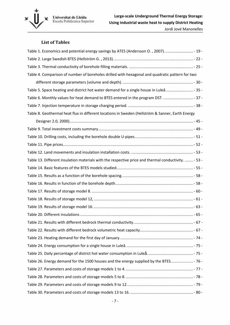
Figure 12. The borehole spacing depending on the pattern. ............................................................ - 30 -
Figure 13. Storage divided in 7 sections, it has a manifold for each section that comes together in two
main manifolds (Andersson & Leif, 2012). ................................................................................ - 32 -
Figure 14. Thermal Response Test set-up. ........................................................................................ - 33 -
Figure 15. Location of Luleå in the European map. ........................................................................... - 34 -
Figure 16. Total monthly heat demand and monthly mean air temperature. .................................. - 36 -
Figure 17. Duration curve for the annual heating demand of the 1500 houses. .............................. - 37 -
Figure 19a. Overview of energy system in Luleå. .............................................................................. - 38 -
Figure 19b. Energy flows in the Luleå energy system. ...................................................................... - 38 -
Figure 20. District heating price and prediction. ............................................................................... - 39 -
Figure 21. DST model cylindrical shape and hexagonal distribution................................................. - 41 -
Figure 22. Lithological map from Geological Survey of Sweden (SGU). ............................................ - 43 -
Figure 23. Borehole top view. ........................................................................................................... - 44 -
Figure 24. Ground temperature profile in Luleå. .............................................................................. - 45 -
Figure 25. Pressure drop and volume as a function of the injection flow rate. ................................ - 46 -
Figure 26. . Comparison between simulation temperature and real temperatures, values in monthly
average. ..................................................................................................................................... - 48 -
Figure 27. Transient and steady-state heat losses. ........................................................................... - 51 -
Figure 28. Energy injection, extraction and losses evolution during 10 years in storage model 7. .. - 56 -

Large-scale Underground Thermal Energy Storage:
Using industrial waste heat to supply District Heating
Jordi Jové Manonelles
- 10 -
Figure 29. Evolution of injection, extraction and mean storage temperatures during 10 years in
storage model 7. ........................................................................................................................ - 57 -
Figure 30. Annual Storage Cost for the different models with low energy price.............................. - 59 -
Figure 31.Annual Storage Cost for the different models with medium energy price. ...................... - 61 -
Figure 32. Annual Storage Cost for the different models with high energy price. ........................... - 62 -
Figure 33. Annual Storage Cost for the different models with expensive price. .............................. - 64 -
Figure 34. Annual Storage costs with different insulation layers. Data: Energy price 0,15 SEK/kWh;
λA=0,13 W/m,K, λB= 1,4 W/m,K and λC=0,036W/m,K; thickness: zA=0,4m, zB=1m, zC=0,5m .. - 65 -
Figure 35. Annual Storage costs with different insulation layers. Data: Energy price 0,35 SEK/kWh;
λA=0,13 W/m,K, λB= 1,4 W/m,K and λC=0,036W/m,K; thickness: zA=0,4m, zB=1m, zC=0,5m. . - 66 -
Figure 36. System distribution: pipes and boreholes. (optimum storage: model 12) ...................... - 68 -
Figure 37. Storage model 8, temperature graph with Inlet T (red line), Outlet T (blue line) and Mean
Storage T (green line) ................................................................................................................ - 86 -
Figure 38. Storage model 12, temperature graph with Inlet T (red line), Outlet T (blue line) and Mean
Storage T (green line) ................................................................................................................ - 90 -
Figure 39. Storage model 16, temperature graph with Inlet T (red line), Outlet T (blue line) and Mean
Storage T (green line) ................................................................................................................ - 94 -
Figure 40. Total and borehole pipe pressure drop ............................................................................ - 96 -

Large-scale Underground Thermal Energy Storage:
Using industrial waste heat to supply District Heating
Jordi Jové Manonelles
- 11 -
1 Introduction
1.1 Abstract
The city of Luleå is growing and the municipality is looking to build a new urban area for about 5 000
people in an old air military area called Kronan. The concept is to build a green residential area, but
no details have been decided yet.
Usually the space heating in the Swedish cities is supplied by a municipal district heating system.
Luleå takes advantage of the gases generated in the local coke and steel plants. Using these gases as
fuel in a co-generation plant, which is connected to Luleå’s district heating system, means that the
Luleå community has the cheapest district heating in Sweden (Luleå Kommun, 2014). The heat
produced by these gases can easily supply the heat demand when the temperature is above -10oC,
but when it is colder than -10oC additional energy is required and there are different plants to
provide it. This extra energy comes from electricity and oil. In total, heat from the waste gases covers
about 90 % of the district heating.
Moreover, the steel plant works the whole year while space heating demand depends on the
weather. When there is no demand, the heat generated in the plant is mostly dumped into the
Bothnian Bay, which means a significant waste of energy.
This project studies the possibility to store this waste heat in summer in order to supply space
heating to the new residential area. This storage procedure is possible using a borehole thermal
energy storage and the optimum parameters depend on the energy price.
The storage cost estimated is between 34 and 41 MSEK , with a payback of 7 to 9 years and it is able
to supply 14 GWh/year during the winter months fulfilling the heat demand for the new
neighborhood. The energy efficiency of the storage is above 75% from the fifth year of operation,
which means barely 18GWh of waste heat will be used to supply the district heating.
1.2 Objective
The aim of this project was to investigate seasonal storage of waste heat in a borehole thermal
energy storage (BTES) system to supply it to the new urban area in Kronan during the demand
period. The main objective is to provide the total heating demand for Kronan, including the domestic
hot water.
In order to estimate the heat demand for this new urban area of 1500 new dwellings (single-family
houses, a mean annual heat demand of 12 MWh/dwelling is assumed, which means that 18,000
MWh is annually needed to heat the new buildings. The annual waste heat from the steel plant is
250-500 GWh, but a large share of this waste is of low temperature, i.e. below 20oC (Skogsberg,
2014).

Large-scale Underground Thermal Energy Storage:
Using industrial waste heat to supply District Heating
Jordi Jové Manonelles
- 12 -
2 Background
2.1 Energy consumption
Nowadays one of the most urgent issues is the World energy consumption, better said
overconsumption. The human civilization is consuming approximately 1.5 times more resources than
Earth can sustain, (The Living Planet, 2012), leading to exhaustion of the resources. The fact is that
the problem is accelerating since, as demonstrated for energy in Figure 1, the consumption is still
increasing despite all previous global measures. The consumption of energy resources follows rather
well the overall consumption of resources since energy is required to utilize other natural resources.
Figure 1. Global Energy consumption by Our Finite World 2012.
In order to slow down the exhaustion of energy resources, and thereby increased energy costs, the
International Energy Agency (IEA) promotes renewable energies, more efficient use of energy, and
energy storage technology.
The IEA's Energy Conservation through Storage (ECES) programme has held international global
energy conferences since 1981. The first three conferences were held every second year (until 1985)
and since 1988 the conferences have been held every third year. The most recent was
Innostock´2012 (the 12th International Conference on Thermal Energy Storage) in Lleida, Spain. The
next conference, Greenstock´2015, will be held in Beijing, 19-21 May 2015.

Large-scale Underground Thermal Energy Storage:
Using industrial waste heat to supply District Heating
Jordi Jové Manonelles
- 13 -
2.2 Energy cost
The decreasing oil (fossil energy) resource, which is currently the most important source of energy,
means that the price of the energy is increasing (see Figure 2). This has resulted in greater interest in
renewable energy resources. Apart from being environmentally benign, they have low operation
costs.
Figure 2. Nominal price developments for 3 fossil fuels in the European market. Price in US dollars per Ton Oil Equivalents.
At the same time these fossil fuel resources such as oil, natural gas and coal are increasingly less
available.
2.3 Waste energy
Despite the increasing energy cost a substantial part of used energy is wasted, in all sectors of
society. Even though a large portion of wasted energy could be saved by simple and inexpensive
measures, much of the savings would require larger investments in the energy system.
Most of the wasted energy is heat because of for example poor insulation of buildings or bad or no
systems to control and regulate the heating, cooling and ventilation demand, where simple means
would make a big difference.
Recycling of heat and also using household waste as an energy resource is quite common in Europe.
When it comes to recycling of household waste, Sweden is very successful as just four percent goes
into landfills. The rest winds up either recycled or used as fuel in waste-to-energy power plants
(Public Radio International, 2014). Burning the garbage in the incinerators generates 20 percent of
Sweden’s district heating. Sweden has been so successful that it imports waste from neighboring
countries.

Large-scale Underground Thermal Energy Storage:
Using industrial waste heat to supply District Heating
Jordi Jové Manonelles
- 14 -
One way to further increase recycling of heat is to store it for use at a later time; it could mean
storage between day and night but also between the seasons. Here is where the field of Energy
Storage becomes significant.
2.4 Energy Storage (ES)
The importance of energy storage has been increasing in past years and will continue growing; the
main reason being that the many important renewable energy resources are intermitent, and
generated when weather dictates, rather than when energy demand dictates (Hammerschlag &
Schaber, 2007). The huge potential of energy sources substituting fossil fuels can only be exploited by
energy storage systems, utilizing renewables such as solar thermal, photovoltaic and wind energy.
Dincer and Rosen (2011) summarized the significant benefits from use of ES systems as follows:
� Reduced energy costs.
� Reduced energy consumption.
� Improved indoor air quality.
� Increased flexibility operation.
� Reduced initial and maintenance costs.
� Reduced equipment size.
� More efficient and effective use of equipment.
� Conservation of fossil fuels.
� Reduced pollutant emissions.
� Peak shaving & peak shifting.
There are a number of promising areas of research in ES technology. Given the potential benefit of ES
applications it is clear that a sustained development effort is necessary. Some current research and
development areas in the field are as follows (Dinser & Rosen, 2011):
� Advanced ES and conversion systems with phase transformations, chemical and
electrochemical reactions.
� Engineering integration of whole battery packs into vehicles.
� High-dielectric-constant polymers.
� High K composites for capacitors.

Large-scale Underground Thermal Energy Storage:
Using industrial waste heat to supply District Heating
Jordi Jové Manonelles
- 15 -
� Polymer electrode interfaces (low and high-frequency effects).
� Integrated polymer capacitors.

Large-scale Underground Thermal Energy Storage:
Using industrial waste heat to supply District Heating
Jordi Jové Manonelles
- 16 -
3 Thermal Energy Storage (TES)
Among the different energy storage methods, the one used in this project is Thermal Energy Storage
(TES).
Thermal energy may be stored by altering the sensible heat of a substance, by changing the phase of
a substance or through a combination of both. These technologies are useful for storing energy from
systems that provide heat as a native output (e.g., solar thermal, geothermal), or for applications
where the energy´s commodity value is heat (e.g., space heating, cooling, drying).
The TES systems are numerous and include designed containers, underground aquifers, soils, lakes,
bricks and ingots. But always the energy is stored by cooling, heating, melting, solidifying, or
vaporizing a material; and the thermal energy becomes available when the process is reversed.
The energy E required to heat a volume V of a substance with a volumetric heat capacity heat c from
a Temperature T1 to a temperature T2 is defined by the equation ( 1 ) (Cengel, 2002):
� = � ∙ � ∙ (� − ��) ( 1 )
When the system consists in elevating or lowering a material temperature it is called sensible heat
storage. Its functionality depends on the material thermal properties, mainly in specific heat.
However when the system consists in a material transition from solid to liquid or liquid to vapor it is
called latent heat storage. While sensible storage normally uses rocks, ground or water as storage
media, the latent heat storage uses phase change materials (PCMs) and the specific heat of fusion or
vaporization are main design parameters.
The selection of a TES system is subject to different factors such as period required, economic
viability, energy volume, operation conditions and so on.
In some situations the TES have a dual functionality, not only keeping the energy for later use, but
also being involved in other processes. One example is the following:
Plants and factories need cooling processes due to the fact that they are not perfectly
efficient and they produce heat during the manufacturing or energy transformation. Because water is
a perfect medium to dissipate heat and it is easily accessible many plants are located close to the sea
or rivers. But instead of throwing back this warm water, as they normally do, it can be stored for
other necessities, such as internal space heating or pre-heating in other processes. That would avoid
thermal pollution and improve the plants overall efficiency.
The ES systems can be divided in two different groups depending on the storage period: Short-term
and seasonal storages. In some climates there is a heat demand during winter and also a cooling
demand during summer; with the seasonal storage it is possible to match the annual demand. The
storage is charging heat from the warm summer and supplies it when it is required, while at the time

Large-scale Underground Thermal Energy Storage:
Using industrial waste heat to supply District Heating
Jordi Jové Manonelles
- 17 -
the storage is charging cool from the cold winter to supplies it in summer. A short-term storage
application on the other hand would be in single house solar systems with a tank, the objective of
which is to store the energy from the night to supply it the following morning.
3.1.1 Barriers to TES
Although all the advantages of TES technology are not always taken into account when considering it
as a real option, due to the following reasons mentioned by Dincer and Rosen (2011):
� Lack of proper information.
� Lack of commercial options.
� High initial cost.
� Infrastructure restrictions.
The high initial costs can be alleviated with funds as financing for TES investment is available from
the European community. But the biggest disadvantage for large storage is the infrastructure
constraints; depending on the location the media is not suitable for a TES system.
3.2 Underground Thermal Energy Storage (UTES)
The most common methods for large scale thermal energy storage (i.e. heat or cold storage) are
sensible storage in aquifers (ATES) and in the bedrock through borehole heat exchangers (BTES).
Another option is underground caverns (CTES), but this concept has so far rarely been applied
commercially (Andersson O. , 2007).
The site specific conditions, geology and groundwater etc., are determining factors in deciding which
UTES system could be implemented; each system needs different media and size, and for that reason
not all locations are suitable. However, if one cannot find a suitable aquifer for ATES, it is almost
always possible to use boreholes to create a BTES system. But, the underground conditions will
always determine the system efficiency and this is therefore the most important factor.
To have a proper thermal performance, any UTES system needs a certain size. If not, the stored
thermal energy will be lost in temperature quality due to thermal losses to the surroundings. The
thermal losses will reduce the UTES performance and it is therefore important to carefully determine
the ground conditions.
3.2.1 Application of UTES
Around the world there are contrastive types of climates and in each one are different potential
applications for UTES. The following are some of these possible applications:
� Space heating in residential, commercial and industrial buildings.

Large-scale Underground Thermal Energy Storage:
Using industrial waste heat to supply District Heating
Jordi Jové Manonelles
- 18 -
� Air conditioning in residential, commercial and industrial buildings.
� Process cooling in manufacturing industries, telecom applications, IT facilities and electric
generation with combustion technologies.
� Cooling for food preservation and quality maintenance.
� Cooling and heating for growing agricultural products in greenhouses.
� Cooling for fish farming in dams.
3.3 Rock Cavern Thermal Energy Storage (CTES)
In the Rock Cavern Thermal Energy Storage (CTES) the energy is stored as hot water in an
underground cavern. Potential structures for CTES include abandoned mines, tunnels and rock
caverns, and specially constructed caverns for thermal energy storage.
As seen in ¡Error! No se encuentra el origen de la referencia. the pipes for extraction and injection
reach different depths, because during the injection the hot water is released in the upper part of the
store while the colder water is extracted from the bottom, in this way the volume of water gets a
stratified profile. There are also systems, e.g. the Lyckebo storage (Uppsala, Sweden) with has a
“telescope” injection pipe, where the hot water is always injected at the same temperature as the
temperature of injected heat.
Like the other underground energy storages during the first years of heat injections there is
substantial energy loss to the surrounding rock. However, during the first few years of charging, the
cavern develops a relatively stable thermal halo around itself with decreasing temperature away
from the hot center (Sang Lee, 2013).
Figure 3. Rock Cavern Thermal Heat Energy Storage

Large-scale Underground Thermal Energy Storage:
Using industrial waste heat to supply District Heating
Jordi Jové Manonelles
- 19 -
The advantage of CTES is the high injection and extraction powers which are mainly a function of
pumping capacity and sizing of the heat exchangers, while the disadvantage is its high construction
costs.
There are just a few examples of CTES in the world and the first two were built in Sweden in the early
1980s. One of them is the Avesta CTES which was built in 1981 for short-term energy storage of heat
produced at an incineration plant with 15 000m3 volume and the Lyckebo CTES with a storage
volume of 115,000 m3, which is connected to the Uppsala district heating net (Nordell B. , 2012). The
CTES may also be used for storing snow as phase change material energy storage (PCMES).
3.4 Aquifer Thermal Energy Storage (ATES)
The Aquifer Thermal Energy Storage (ATES) is a direct water heat exchanger system for large scale
systems mainly for seasonal thermal energy storage both heating and cooling.
In the ATES systems thermal energy is stored in the ground water of an aquifer. The system consists
of two or multiple wells used to extract water from the aquifer which is heated or cooled before it is
re-injected. The wells are drilled separately in two groups in order to keep one part of the aquifer
warm and the other part cold.
ATES are not as easy to construct as BTES, and need more maintenance and pre-investigations to get
the authority approval, due to the protection of groundwater resources and environmental impact
(Sang Lee, 2013).
However, the investment in ATES systems is not significantly higher than a conventional system and
since the operational cost is much less due to energy savings, the ATES system is normally quickly
paid off. Depending on the type of system the payback will vary, as can be seen in
Table 1 where the values are obtained from Swedish applications with the performance factor (PF)
and the energy savings in respect to the conventional systems, these latter consist of fossil fuels or
electricity for heating or district cooling for air conditioning.
Table 1. Economics and potential energy savings by ATES (Andersson O. , 2007).
One example of ATES is at Stockholm Arlanda Airport (Figure 4), the largest airport in Sweden. This
installation started its operation in the summer of 2009.

Large-scale Underground Thermal Energy Storage:
Using industrial waste heat to supply District Heating
Jordi Jové Manonelles
- 20 -
In the winter this ATES is used for preheating of ventilation air and for snow melting off the ramps at
the gates. This way the water of the aquifer is cooled down during the winter. In the summer this
cold water is used for comfort cooling. The waste cold from heating is distributed back and stored at
the cold side of the aquifer. The cold storage temperature varies from +3 to +5°C under normal
conditions. Before this system was taken into operation heating was supplied by district heating.
The ATES plant at Stockholm Arlanda has lowered the energy consumption, with a reduced electricity
use for cooling production by 4 GWh/year and the district heating use by 15 GWh/year. The cost of
energy has thereby been annually reduced by at least 1 M€ for an investment of approximately 5 M€.
The system’s efficiency is very high since no heat pumps are used and its seasonal performance
factor of about 60 means that it is practically insensitive to future energy fluctuations.
3.5 Borehole Thermal Energy Storage (BTES)
The Borehole Thermal Energy Storage (BTES) consists of a network of vertical ground heat
exchangers drilled on the ground or also called borehole heat exchangers (BHE), which are closely
and uniformly spaced. Inside of the boreholes different duct types are used as heat exchangers to
heat or cool the ground source, this ground is the volume where the heat is stored and it is
composed of soils and rocks. A fluid pumped through the ducts, called heat carrier fluid, is the heat
transmission medium for both extraction and injection. During the energy injection the heat is
transferred from the heat carrier fluid to the borehole wall, in different ways depending on the
system, and from the borehole wall conducted to the surrounding rock, while the energy extraction
follows the opposite way when the store is at higher temperatures than the heat carrier fluid.
BTES systems are easier to construct and operate than ATES, need limited maintenance and have
long durability. Moreover, BTES systems usually require only simple procedures for authority
approvals. Another advantage with respect to ATES is that it is less dependent on site-specific
conditions, therefore BTES provides an alternative for areas where groundwater conditions are
insufficient. But while ATES needs just a few thermal wells, BTES needs a large quantity of boreholes
for large-scale thermal energy storage, see Figure 5.
Figure 4. Arlanda airport ATES installation

Large-scale Underground Thermal Energy Storage:
Using industrial waste heat to supply District Heating
Jordi Jové Manonelles
- 21 -
As has been said there are different systems for the heat transfer to the storage volume, mainly
closed and open system. The most common systems are the closed ones with U-pipes or double U-
pipes, which have the heat carrier fluid circulating through the pipes and another fluid or a mix of
fluids and solids as a borehole filling material.
Depending on the stored temperature the system is considered low temperature heat storage
(T<40oC) or high temperature heat storage (T>40oC). Usually with the last case the heat is used
directly for its purpose while in the first case a heat pump is used to reach higher temperatures and
fulfill its objective, e. g. space heating.
There has been an increasing interest for high temperature heat storage in recent years with the idea
to store waste heat and solar heat and recover stored heat without heat pumps. To achieve this aim,
storage volumes are getting larger and the heat is distributed at lower temperatures such as floor
heating or other lower temperature applications (Nordell B. , 2012).
3.5.1 Applications
BTES are the most commonly implemented UTES; it is feasible in a very small scale and also in large
scale, due to BTES system is suitable to different dimensions and objectives.
Nordell (2000) summarized the different applications of the BTES system.
� Small-scale systems:
- Single borehole for cooling.
- Single borehole for heating with heat pump.
- Single borehole for heating with heat pump and direct cooling.
� Large-scale systems:
- System of boreholes for heat extraction with heat pump.
Figure 5. BTES operation. Cooling during summer (left) and heating during winter (right). (Underground Energy LLC, 2014)

Large-scale Underground Thermal Energy Storage:
Using industrial waste heat to supply District Heating
Jordi Jové Manonelles
- 22 -
- System of boreholes for heat extraction with heat pump and recharging of extracted
energy.
- Seasonal loading of thermal energy for later extraction.
- Seasonal loading of thermal energy for the purpose of cooling or heating the ground.
A couple of million BTES systems have been constructed around the world. The Geothermal Heat
Pump Consortium (GHPC) estimates that 400.000 BTES systems will annually be built in the United
States within a few years. Most of them are borehole systems of one or a few boreholes (Sang Lee,
2013). However, the number of large-scale BTES is also increasing. Table 2 shows the largest built
BTES to be in Sweden.
Table 2. Large Swedish BTES (Hellström G. , 2013).
Project Location Boreholes Bore depth (m) Total (m)
Karlstad University Karlstad 204 240 48240
Brf. Ljuskärrsberget Stockholm Saltsjöbaden 156 230 35880
Kemicentrum (IKDC) Lund 153 230 35190
Lustgården Stockholm 144 230 33120
Vällingby Centrum Stockholm 133 200 26600
Brf. Igelbodaplatån Stockholm Saltsjöbaden 120 200 24000
Kv. Bergen Stockholm Husby 98 215 21070
ITT Xylem Emmaboda 140 150 21000
Kv. Galgvreten Enköping 86 220 18920
Copperhill Mountain Lodge Åre 92 200 18400
Centrala Gribbylund Täby 87 210 18270
Thulehem Lund 86 200 17200
IKEA Uppsala 100 168 16800
NIBE Markaryd 110 150 16500
Centralsjukhuset Karlstad 80 200 16000
Backavallen Katrineholm 91 172 15652
IKEA Karlstad 100 120 12000
Musikhögskolan Örebro 60 200 12000
Sjukhuset Kristinehamn 55 210 11550
Vattenfalls Huvudkontor Solna 53 200 10600
IKEA Helsingborg 67 150 10050
Stenungsbaden Yatch Club Stenungsund 50 200 10000
Näsby Parks Slott Stockholm 48 180 8640
Projekt Lulevärme Luleå 120 65 7800

Large-scale Underground Thermal Energy Storage:
Using industrial waste heat to supply District Heating
Jordi Jové Manonelles
- 23 -
4 BTES. System description
In order to design a BTES there are several factors that have direct influence. Some of these
parameters may be chosen to find the optimum effectiveness, but others are constraints related with
the storage location that is impossible to vary, for that reason it is very important to analyze and test
the area to find the best place to locate the storage.
4.1 Ground thermal properties
The thermal properties of the ground are of primary importance for the storage design. The capacity
to inject, extract and store is determined mainly by the thermal conductivity and the volumetric heat
capacity.
4.1.1 Thermal conductivity
Thermal conductivity is a measure of the ability of a material to conduct heat. The deeper the soil
layer is, the better the thermal conductivity will be for the storage because it will reduce the losses
from the top of the storage due to the ambient temperature, it works as an insulation layer.
Regarding the bedrock, although a higher thermal conductivity worsens the energy efficiency
because it increases the losses to the surroundings, it is better for the storage because it improves
the heat transfer from the heat carrier fluid to the storage volume, enhancing the storage capacity to
inject and extract, which means less surface is needed for the heat exchange.
4.1.2 Volumetric heat capacity
Volumetric heat capacity is a measure of the ability of a given volume of a substance to store internal
energy while undergoing a given temperature change. With a bedrock material with higher
volumetric heat capacity less volume will be needed to store the same amount of energy.
In contrast, volumetric heat capacity in the soil layer is not important as it does not significantly
affect the results.
4.1.3 Geothermal Gradient
The vertical temperature gradient or Geothermal Gradient is the rate of increasing temperature with
respect to increasing depth from a given reference point (equation ( 2 )). The underground
temperatures are increasing with depth according to the temperature gradient.

Large-scale Underground Thermal Energy Storage:
Using industrial waste heat to supply District Heating
Jordi Jové Manonelles
- 24 -
= � ∙ ����
( 2 )
Where: q is the geothermal heat flux (W/m2)
λ is the thermal conductivity (W/K,m).
��
�� is the temperature gradient (K/m).
In Sweden the geothermal gradient is generally
about 0,01 K/m, but there are locations with
gradients of 0,02-0,03 K/m in mountainous areas
with geologically young rocks (Nordell B. , 1994).
Figure 6 shows a typical ground temperature profile.
Seasonal temperature variations do not reach below
15 meters from the ground surface (Ericsson, 1985).
4.2 Heat carrier fluid
The heat carrier fluid is the fluid pumped through the pipes. Water is unique among materials in
having an abnormally high specific heat of 4,186 J/Kg K, and furthermore has a reasonable density.
Water is also cheap and safe.
Liquids other than water may need to be chosen if the delivery temperature must be higher than
100oC, or if the system temperatures can fall below 0oC (Hammerschlag & Schaber, 2007). When the
temperature could be close to or below zero degrees it is necessary to mix water with a percentage
of other liquid with a lower freezing point, such as methanol (-97.6°C) or ethanol (-114°C).
4.3 Filling material
The boreholes require some kind of backfilling material to fill the space between the pipe or pipes
and the borehole wall. In order to provide good thermal contact between the pipe and the
surrounding soil, the borehole is filled with a high thermal conductivity grouting material.
Moreover, it is possible to mix a liquid with different solids to produce a grouting material with
higher thermal conductivity, see Table 3. A good example is the Drake Landing BTES in Alberta
Figure 6. Temperature profile in the ground.

Large-scale Underground Thermal Energy Storage:
Using industrial waste heat to supply District Heating
Jordi Jové Manonelles
- 25 -
(Canada) where a high solids grout composed of 9% Blast Furnace Cement, 9% Portland cement, 32%
fine silica sand and 50% water is used as a filling material (Drake Landing Solar Comunity, 2014).
The mixtures must be pumpable to fill the boreholes during the installation. But in Sweden and
Norway it is common to leave the boreholes ungrouted, i.e., the boreholes are filled with
groundwater (Sang Lee, 2013).
Table 3. Thermal conductivity of borehole filling materials.
Material Thermal conductivity (W/m,K)
Water 0,56-0,6
Ice 2,2-2,3
Concrete 0,92-2,02
Sand (moist)
Sand (dry)
0,58-1,75
0,27-0,75
Silt (moist)
Silt (dry)
1-2,30
0,38-1
Clay (moist)
Clay (dry)
Bentonite 10 %, in water
Bentonite 20%, in water
Bentonite 40 %, in water
Air
0,9-2,22
0,4-0,9
0,65-0,77
0,64-0,66
0,53-0,82
0,03
4.4 Borehole thermal resistance
The thermal process between the heat carrier
fluid and the borehole wall is defined by the
borehole thermal resistance. This borehole
thermal resistance depends mainly on the
arrangement of the flow channels in boreholes
(see section 4.5) and defines the quality of the
circulation heat transfer. The lower the borehole
thermal resistance is, the greater the heat
transfers, i.e. better energy injection and
extraction.
The value of the borehole thermal resistance is
influenced by the thermal properties of the
different materials which take part in the heat
transfer from the heat carrier fluid to the Figure 7. Borehole thermal resistance for different
circulation systems.

Large-scale Underground Thermal Energy Storage:
Using industrial waste heat to supply District Heating
Jordi Jové Manonelles
- 26 -
borehole wall. The number of influencing factors depends of the circulation system (see Figure 7 and
Figure 10), but basically the following are relevant:
- Heat carrier fluid.
- Closed pipe material.
- Borehole filling material.
- Bedrock material.
4.5 Open and closed system
As mentioned above in section 3.5, there are different circulation installations, but only two basic
types. In an open system the heat carrier fluid is directly in contact with the borehole wall, whereas
in a closed system the heat carrier fluid is circulated in a closed pipe system through the boreholes.
4.5.1 Open systems
This system consists in a circular concentrically
placed pipe through which the water is injected or
extracted. It has one or multiple holes at the bottom
to let the water flow through it and circulate in the
annular part in direct contact with the borehole
wall, another pipe takes up or injects the water from
or in the annular volume. The flow direction is
reversed depending on the mode of operation,
charging or discharging the storage. One example of
open system is the Emmaboda (Sweden) storage
which has been working since 2010. Figure 8 shows
the BHE used in each of the 140 boreholes of the
storage.
The main advantage of this circulation system is the
low value of borehole thermal resistance, that it is
approximately 0,03 W/mK depending on the pipe and rock materials, which means a good heat
transfer between the fluid and the rock.
The disadvantage is the water circulating through the pipe is also in direct contact with the borehole
wall, that fact produces water chemistry problems and potential problems with clogging and
corrosion. Particles or dissolved materials from the rock and also corrosion of the steel pipes are the
Figure 8. BHE used in Emmaboda storage in an
open circulation system.

Large-scale Underground Thermal Energy Storage:
Using industrial waste heat to supply District Heating
Jordi Jové Manonelles
- 27 -
risks in an open system, because it changes the water properties increasing the content of oxygen
and CO2 and lowering the pH value, which increases the risk of corrosion of steel pipes.
Figure 9 shows the revealed precipitation of dirt, cuttings and iron hydroxide when the heat
exchanger was flushed after almost one year of operation in the open system of Emmaboda BTES.
Figure 9. Cleaning of the heat exchanger after one year of operation in Emmaboda BTES.
There is an “open” system which has been created to avoid these disadvantages, it uses a thin plastic
lining protection in the borehole walls that increases the borehole thermal resistance just a little. But
this system has so far only been utilized in tests and investigations, not in large-scale cases.
4.5.2 Closed systems
The closed system is the most common among BTES, consisting of one or multiple pipes placed into
the boreholes, which are backfilled with water or grouting material. The heat carrier fluid is pumped
through the pipes and the heat is transferred to the pipe wall and from this to the filling material and
finally to the borehole wall.
The most usual closed systems are the single U-pipes and double U-pipes, but there are others such
as the concentric or triple U-pipe, see Figure 10. These U-pipes are small channels located close to
the wall. Due to the narrow diameter the flow is laminar at high velocities, but to improve the heat
transfer the flow must be turbulent.
Figure 10. Different closed systems.

Large-scale Underground Thermal Energy Storage:
Using industrial waste heat to supply District Heating
Jordi Jové Manonelles
- 28 -
The advantage of this system is that the heat carrier fluid is never in direct contact with the rock,
therefore it keeps its properties constant and does not damage the process during its operation.
The borehole thermal resistance for the double U-pipe and single U-pipe is approximately 0,08 W/mK
and 0,11W/mK respectively, depending on the heat carrier, filling material, pipe and rock thermal
properties.
4.6 Storage Shape
The most appropriate shape for a BTES would be spherical because the losses would be minimum
avoiding corners. But this shape is not possible to implement and the closest is a cylindrical shape.
4.6.1 Borehole depth
Theoretically, the proper depth for the heat storage would be when the depth has the same value as
the sides, in a square surface. Thereby, the losses are minimized. But usually the depth is larger than
the sides to reduce the surface needed to store the same amount of energy, because of the surface
price and the expense of drilling the soil layer, the price is twice the rock drilling cost (see section
7.4), for these economic reasons is common drill less boreholes but deeper.
Since the extra cost for digging deeper than 200 meters is just about 5% per meter (see section 7.4),
it will be cheaper to dig the boreholes as deep as it is possible. That depends on the surface needed,
but if the number of boreholes is less it means a reduction in the total cost.
Based on previous experiences despite the model prices we have, a further cost increase is expected
when the digging and piping gets complicated because of the depth. For that reason boreholes
deeper than 250 meters are rarely drilled.
Moreover, one detail that must be considered is that it is convenient to leave a distance between the
borehole bottom and the U-pipes, due to falling sediments and thermal expansion. In a large-scale
BTES located in Anneberg (Sweden), where this was not considered, the pipes were broken after an
operation period and they had to be removed and fixed. A good example could be the storage in
Emmaboda where the security distance between borehole bottom and pipe is 4 meters.
Effective depth
The distance between the groundwater levels to the borehole bottom is called effective depth or
also called the active part of the borehole and it is the section in which heat transfer from the fluid to
the rock takes part.

Large-scale Underground Thermal Energy Storage:
Using industrial waste heat to supply District Heating
Jordi Jové Manonelles
- 29 -
4.6.2 Borehole Spacing
The spacing is the distance between the borehole centers and it directly influences the storage
design. When the boreholes are placed closer the storage has fewer losses and it is easy to increase
the mean temperature during the heat injection, but it also decreases faster during the heat
extraction.
The holes are drilled either in a quadratic or hexagonal pattern (see Figure 11). The hexagonal
pattern is better regarding energy losses and heat transmission, but usually the large storages use
the quadratic pattern, which involves drawing tracks on the surface that facilitate the work and the
machinery transit and also makes it simpler to drill and install the piping between boreholes.
Figure 11. Borehole spacing patterns: quadratic (left) and hexagonal (right)
In a certain volume if the same spacing is used for both patterns the number of boreholes will be
different due to the borehole cross sectional area, furthermore the equivalence between quadratic
and hexagonal pattern can easily be known using the same cross sectional area, see equations ( 3 )
and ( 4 ). One example is shown in Table 4, where two different storage parameters are calculated
with the same spacing to appreciate the difference in the number of boreholes drilled, as equations
( 3 ) and ( 4 ) prove the relation between the number of boreholes with the different drilling patterns:
No Boreholes quadratic pattern is 0,866 times the No of boreholes in hexagonal pattern.
���������� = ����� ! ( 3 )
�"#$�%&'�( = √3 ∙ ����� !2
, 0.866 ∙ ����� ! ( 4 )
Large-scale Underground Thermal Energy Storage:
Using industrial waste heat to supply District Heating
Jordi Jové Manonelles
- 30 -
Figure 12. The borehole spacing depending on the pattern.
In the hexagonal pattern the spacing equals one half of the apothem, while in the quadratic it equals
the side (see Figure 12).
Table 4. Comparison of number of boreholes drilled with hexagonal and quadratic pattern for two different storage
parameters (volume and depth).
Drilling
pattern
Volume
(m3)
Depth
(m)
Total Surface
(m2)
Spacing
(m)
Surface/
borehole (m2)
Number of
boreholes
Hexagonal 300 000 150 2 000 4,0 13,9 144
Quadratic 300 000 150 2 000 4,0 16,0 125
Hexagonal 800 000 200 4 000 4,5 17,5 228
Quadratic 800 000 200 4 000 4,5 20,3 198
Considering the commonly used quadratic pattern the usual spacing in large BTES is 4 meters.
However it is possible to find storages with 2.5 to 6 spacing meters, this depends on the storage
characteristics such as borehole depth and energy price. For example, when the energy cost is very
expensive, for example if it is provided by solar collectors, then a shorter distance between boreholes
is preferable to avoid further losses, whereas when the energy used is waste energy the spacing
could be higher than 4 meters because the energy loss is not the most significant cost.
4.6.3 Storage volume
In order to calculate the storage volume there are a couple of details that must be considered. Firstly
the depth used in the calculation is the effective one (see section 4.6.1). Secondly in the surface area
half of the borehole spacing must be added for each side in square surface, if the surface is circular
the borehole spacing must be added once to the BTES diameter.
Moreover the storage volume needed to storage a certain amount of energy can be estimated using
equation ( 5 ):

Large-scale Underground Thermal Energy Storage:
Using industrial waste heat to supply District Heating
Jordi Jové Manonelles
- 31 -
� = �∆� ∙ � ( 5 )
Where V: Storage volume (m3)
E: Energy to store (kWh)
c: Volumetric heat capacity of bedrock (kWh/m3,K)
T: Temperature difference of the volume (K)
However this equation does not consider the energy losses, which depend on storage shape and soil
parameters.
4.7 Pipes
The BTES consists in a pipe network and there are multiple possibilities to arrange it. The borehole
pipes can be connected in parallel, in serial or in a combination serial-parallel. The difference is
noticed in the pump, because when the boreholes are connected in parallel the pump just has to
provide the power to overcome the depth of one borehole, while if there are serial connections the
pump has to provide the power to overcome the depth of the number of boreholes connected in
serial.
Usually the borehole pipes are connected to two collectors, one for the injection and another for the
extraction/return. These collectors are finally connected to two main manifolds.
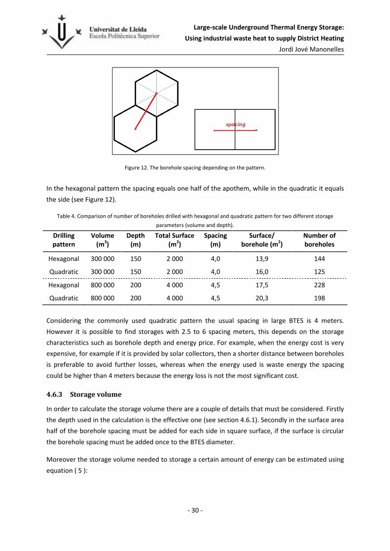
In some cases the storage is divided in sections with the aim to get a stratified volume, in those cases
where the injection load is not enough to heat up all the storage it is injected in the central section or
sections. Also, when the extraction temperature needed is higher than the mean storage volume
temperature it is only extracted from the center section or central sections. Figure 13 shows the 7
different sections of Emmaboda (Sweden) storage with 20 boreholes in each section.
Moreover, in the open systems it is necessary to install degas valves due to the increase of water
temperature.
Large-scale Underground Thermal Energy Storage:
Using industrial waste heat to supply District Heating
Jordi Jové Manonelles
- 32 -
Figure 13. Storage divided in 7 sections, it has a manifold for each section that comes together in two main manifolds
(Andersson & Leif, 2012).
4.8 Flow rates
Usually in the Swedish district heating system the supplied flow rate is kept constant while the
ambient temperature is above 0 degrees and only the temperature varies due to the demand, but
when the ambient temperature is below 0 degrees the flow rate is increased proportionally.
In the BTES normally two pumps with different power are installed in parallel to be able to pump
different extraction flow rates depending on the demand.
However, in this case either extraction and injection flow rates are kept constant because what
matters is to simulate the amounts of energy extracted per month.
There is only one factor to consider for the flow rate, it must be turbulent inside the borehole pipe
because with a laminar flow the thermal resistance between the heat carrier fluid and the borehole
walls is too high, which implies poor heat transfer.
4.9 Thermal Response Test (TRT)
One of the first and more important steps to design a BTES is the Thermal Response Test (TRT). The
TRT is an in-situ measurement method used to evaluate the heat transfer parameters to be used in
the BTES design. The thermal response is studied by measuring the change in circulating fluid
temperature over time, which is dependent on the heat transport underground, the heat injection or
extraction rate, fluid flow rate and influencing outside conditions (Gehlin, S., 2002).
The test equipment consists of two systems, one for heat injection and another for heat extraction.
For the heat injection, an adjustable electrical heater supplies the injection energy. For heat

Large-scale Underground Thermal Energy Storage:
Using industrial waste heat to supply District Heating
Jordi Jové Manonelles
- 33 -
extraction a fluid-to-air heat pump connected to a buffer supplies the circulation heat carrier with
cooling power, the heat pump uses the outside air to release the heat (Gustafsson, 2010).
When a large-scale BTES is going to be built
in a certain area a few boreholes in
different points should be drilled to make
the TRT test and decide where the best
location is for the storage depending on the
thermal properties results obtained by the
tests.
Moreover with the first test boreholes it is
possible to identify groundwater fractures
and see the boreholes deviation with a
deviation control device. This deviation will
be almost the same for all the BTES if the
storage is placed closer to that point due to
the bedrock structures. For the optimal
function of the BTES system it is of interest
to have as straight holes as possible, but
during the drilling process it is not possible
to keep it straight.
4.10 Storage Lifetime
A BTES system has no expiration date, but depending on the storage function its operation could
become less efficient. This happens when the storage is used for both heating and cooling, then if the
operation is not balanced and the storage gets warm or cold and loses energetic power.
On the other hand, if the storage function is just heating it does not lose efficiency during the years,
which means that the lifetime of the storage will not depend on technical factors, but rather
economic factors. These economic factors are the following:
� Possibility of considerably increased maintenance costs.
� Reduction in price of another energy source i.e. cheaper alternative.
� New funds for another energy source.
� The storage location is needed for other services with greater economic potential.
Figure 14. Thermal Response Test set-up.

Large-scale Underground Thermal Energy Storage:
Using industrial waste heat to supply District Heating
Jordi Jové Manonelles
- 34 -
5 Energy demand in Kronan
5.1 Kronan, Luleå.
Luleå is a city with 75000 inhabitants located in the north of Sweden, 70 km south of the Polar Arctic
Circle, see map in Figure 15. Due to its location the winter is longer and it reaches temperatures
below -30oC, which indicates the importance of reliable heating systems.
Figure 15. Location of Luleå in the European map.
From 2003 to 2012 Luleå population increased by 2668 inhabitants and by 2022 an increase of 3150
or more is predicted (Larsson, 2013). Thus, the municipality is planning to expand the Kronan district
with 1500 new houses, for about 5000 persons.
Kronan is an area in Luleå close to the city center and is a former military facility. This area belongs to
the municipality and is currently under development.
Commonly the space heating in the Swedish cities is supplied by a municipal district heating system.
Luleå takes advantage of the waste gases generated in the local coke and steel plants (SSAB). Using
this gas as fuel in a co-generation plant, which is connected to Luleå’s district heating system, means
that the Luleå municipality has the cheapest district heating in Sweden (Luleå Kommun, 2014).

Large-scale Underground Thermal Energy Storage:
Using industrial waste heat to supply District Heating
Jordi Jové Manonelles
- 35 -
5.2 Heating demand
In order to design the storage the most important parameter is the amount of stored energy or
rather the recovered energy, as seen previously in equation ( 1 ). This amount of energy is the annual
heat demand for those 1500 new houses.
The calculation of the annual heating demand is made on the basis of hours and is not included in
this project report but it is available for the library as an Excel file called “Kronan, heat demand.xls”.
Nevertheless an example for one day is included in Appendix A.
In Table 5 the calculations have been summarized, showing the space heating (E. heating) and the
district hot water demand (E. dhw) for an average single family house.
Table 5. Space heating and district hot water demand for a single house in Luleå.
Month T. air [
oC]
E. heating [kWh/month]
E. dhw [kWh/month]
E. total [kWh/month]
January -9,4 1 612 306 1 918 February -13,1 1 659 276 1 935
March -1,1 1 103 306 1 409 April 2,9 540 296 836 May 7,4 214 306 520 June 13,8 17 296 313 July 15,6 3 306 308
August 14,1 48 306 354 September 7,8 251 296 547
October 4,2 537 306 843 November -4,5 1 271 296 1 567 December -1,8 1 145 306 1 451
Total 3,0 8 400 3 600 12 000
For the space heating demand the value is simply multiplied by the number of houses, 1500, but for
the district hot water (dhw) another factor is taken into account. This factor is the use of a heat
pump to heat up the dhw, because the regulations require that the dhw temperature must be above
60oC (for a while) to avoid legionella, before it is supplied to the consumer. For that reason part of
this 3600 KWh/year is electricity and the storage does not have to supply this total energy, just the
difference.
The energy required to heat up the dhw is thus partly provided by the storage, while the rest is by
driving energy from the heat pump. This is given by equations ( 6 ) and ( 7 ), in which the heat pump
coefficient of performance (COP) is assumed to be 4.
�234�,�"6 = ��"6 ∙ 71 − 19:;< ( 6 )

Large-scale Underground Thermal Energy Storage:
Using industrial waste heat to supply District Heating
Jordi Jové Manonelles
- 36 -
�3=3>�?@>@�A,�"6 � ��"6 ∙1
9:; ( 7 )
The total heat demand shown in Figure 16 represents the average energy consumption. The figure
also shows how it is related to the mean air temperature. The only month that does not follow the
common temperature function is December, because the year when the data was obtained the
temperature of December was higher than November, which is not usual.
Figure 16. Total monthly heat demand and monthly mean air temperature.
Moreover, we know that all these new dwellings will not be available during the first year as the area
will be developed over a few years. This will cause a slope in heating demand over the years with
lower initial values that favor the storage process. The reason is that during the first years there is
more loss to the surrounding rock and less energy available for extraction. After the first five years of
operation the energy losses will be almost stable for each year, but clearly lower than the first years,
and the system will be able to supply more energy for the district heating.
-15,0
-10,0
-5,0
0,0
5,0
10,0
15,0
20,0
0
500
1 000
1 500
2 000
2 500
3 000[oC][MWh]
Total Monthly Heat Demand
Heatingdemand
Temperature

Large-scale Underground Thermal Energy Storage:
Using industrial waste heat to supply District Heating
Jordi Jové Manonelles
- 37 -
Figure 17. Duration curve for the annual heating demand of the 1500 houses.
A good method to analyze the heating demand is by an Energy duration graph as in Figure 17, which
shows how many hours are necessary to supply a certain amount of power. The required energy is
the area under this curve. It can be seen, logically, there is a peak of energy; the heating demand
above the 5000 kW only represents 265 hours in a year, 3.0% annual. If the BTES system is designed
to cover this peak, then the volume needed will be much larger and less exploitable. For this reason it
is not designed to fulfill this peak and in this short period it is preferable to use another energy
source to meet the demand.
5.2.1 Assumptions concerning heating demand
� The heating demand during the warm months (May to September) is assumed to be supplied
directly from the district heating network, i.e. the heat that charges the storage during those
months is used directly without passing through the storage. Then the energy that BTES has
to supply is summarized in Table 6.
Table 6. Monthly values for heat demand to BTES entered in the program DST.
Month Total Monthly Heat Demand [MWh]
January 2 762
February 2 799
March 1 999
April 1 143
May 0
June 0
July 0
August 0
September 0
October 1 150
0
1 000
2 000
3 000
4 000
5 000
6 000
7 000
8 000
1 1001 2001 3001 4001 5001 6001 7001 8001
Hea
tin
g d
eman
d (
kW)
Hours (h)
Energy Duration
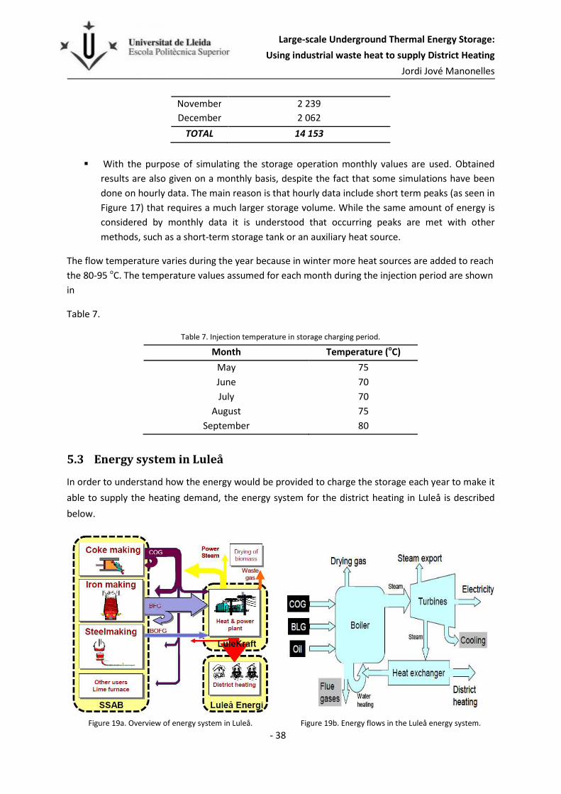
Large-scale Underground Thermal Energy Storage:
Using industrial waste heat to supply District Heating
Jordi Jové Manonelles
- 38 -
November 2 239
December 2 062
TOTAL 14 153
� With the purpose of simulating the storage operation monthly values are used. Obtained
results are also given on a monthly basis, despite the fact that some simulations have been
done on hourly data. The main reason is that hourly data include short term peaks (as seen in
Figure 17) that requires a much larger storage volume. While the same amount of energy is
considered by monthly data it is understood that occurring peaks are met with other
methods, such as a short-term storage tank or an auxiliary heat source.
The flow temperature varies during the year because in winter more heat sources are added to reach
the 80-95 oC. The temperature values assumed for each month during the injection period are shown
in
Table 7.
Table 7. Injection temperature in storage charging period.
Month Temperature (oC)
May 75
June 70
July 70
August 75
September 80
5.3 Energy system in Luleå
In order to understand how the energy would be provided to charge the storage each year to make it
able to supply the heating demand, the energy system for the district heating in Luleå is described
below.
Figure 19a. Overview of energy system in Luleå. Figure 19b. Energy flows in the Luleå energy system.

Large-scale Underground Thermal Energy Storage:
Using industrial waste heat to supply District Heating
Jordi Jové Manonelles
- 39 -
The Luleå energy system consists in three major parts: the SSAB steel plant, the LuleåKraft CHP
(Combined Heat and Power) plant and the district heating system (Luleå Energy), see Figure 19a.
The process gases generated at the steel plant such as coke oven gas (COG), blast furnace gas (BFG)
and basic oxygen furnace gas (BOFG) are partially used in the plant, and the rest is sent to the CHP
plant. There the energy gases are mixed and the result is called BLG (“blandgas” in Swedish i.e. mixed
gas), which is combusted together with supplement oil in a boiler producing steam that reaches
520ºC and is then send to a turbine. The turbine generates about 80 MW and it is divided in four
phases, the steam goes out at 300, 95, 80 and 30 ºC (Elfgren, Grip, Wang, & Karlsson, 2010), see
Figure 19b.
- The 300oC steam is process steam used in the SSAB steel plant.
- The 95oC and 80oC steam are used for district heating by two-step heat exchanger.
- The steam remaining (30oC) is condensed using water from the nearby bay.
All the temperatures are approximate but represent winter conditions.
5.4 District Heating Price
Since the heat injected into this BTES proceeds from the District Heating (DH) network, the DH price
influences both costs and incomes. The BTES incomes are the value of the extracted heat in the
winter, when the DH price is higher due to the law of supply and demand. The heat injection cost is
lower and depends on the deal with the energy company.
Moreover, the DH price varies over the years. Figure 20 shows the prices of the last ten years and the
predicted price evolution for the next fifteen, which are used below in the economic calculations.
30
35
40
45
50
55
60
65
2005 2008 2011 2014 2017 2020 2023 2026 2029
SEKcent
Year
District Heating Price
Energy price
Priceprediction
Figure 20. District heating price and prediction.

Large-scale Underground Thermal Energy Storage:
Using industrial waste heat to supply District Heating
Jordi Jové Manonelles
- 40 -
5.5 Heat source
An important issue that must be considered is the steel plant reliability. There is the possibility that
the steel plant shuts down due to a drop in the steel price or does not produce enough waste energy
to charge the BTES. For that reason other heat sources should be taken into account.
Depending on the source the energy price may vary a lot and the storage parameters must be
changed to find the economically optimum option.
5.5.1 Solar energy
One renewable alternative is to use solar energy although it is an expensive alternative. The cost of
the BTES system will increase at least 5 times if the cost of solar collectors is included. These solar
collectors could be installed directly to the roofs when the new dwellings are built.
In that way the neighborhood would be sustainable. Despite the idea that foreigners might have of
Luleå, there is enough solar energy to carry out the project with this renewable heat source, which
would give the project more repercussion.
However, the storage design is affected by the energy cost and expensive solar heat means that it
would be necessary to design the system In order to reduce the energy losses. There are different
ways to achieve it, by for example:
� Reducing the spacing between boreholes.
� Reducing the surface in contact with the surroundings by decreasing the depth.
� Improving the insulation, either kind of material or thickness.
5.5.2 Other heat sources
The other alternative is to find another large heat source or multiple sources able to supply the
energy needed. One possibility is the Facebook Data Center located in Luleå.
Luleå has the first Facebook data center in Europe and nowadays (2014) another Facebook building is
under construction in the same area. This building uses the chilly Nordic air to cool tens of thousands
of servers that store photos, videos, comments etc. Part of the excess heat produced is used to keep
their offices warm but a large amount of heat is wasted. Although no official numbers are disclosed,
the amount of energy would be enough to charge the BTES.
The BTES could replace the current cooling process by cooling down the data servers and storing this
energy underground for the heating demand.

Large-scale Underground Thermal Energy Storage:
Using industrial waste heat to supply District Heating
Jordi Jové Manonelles
- 41 -
6 The Model
6.1 Duct Ground Heat Storage Model (DST)
The Duct Ground Heat Storage Model (DST) is a simulation model created by Dr. Göran Hellström for
ground heat exchanger systems. The DST calculates the conductive heat transfer in the ground. The
thermal process analyses are divided in three parts: global problem, local problem and steady-flux
(Hellström G. , Duct Ground Heat Storage Model. Manual for computer code, 1989).
The global problem manages the large-scale heat flows in the store and the surrounding ground,
whereas the local problem handles the heat transfer between the heat carrier fluid and the store.
Both are solved with the use of the explicit finite difference method (FDM), whereas the steady-flux
part is given by an analytical solution. The total temperature point is a superposition of these three
parts.
The heat transfer from the fluid to the ground in the immediate vicinity of the duct (borehole) is
calculated with heat transfer resistance. A steady-state heat balance for the heat carrier fluid gives
the temperature variation along the flow path (Pahud & Hellström, 1996).
For computational accuracy and efficiency, the DST model is used in this project to analyze and
design the optimum storage for the specific circumstances of this case.
6.1.1 DST assumptions
The DST program follows some assumptions and others are made for this model.
� DST considers the storage volume has
the cylindrical shape with the axis of
symmetry in the vertical direction. The
numerical mesh is generated
automatically; it is adjusted to the
thermal properties in the ground, daily
changes in loading conditions and
duration of the simulated period
(Hellström G. , 1989). See Figure 21.
� In the model the boreholes are uniformly
placed within the storage volume in a
hexagonal pattern, where the spacing
between them is twice the apothem. See
Figure 21.
Figure 21. DST model cylindrical shape and hexagonal
distribution.

Large-scale Underground Thermal Energy Storage:
Using industrial waste heat to supply District Heating
Jordi Jové Manonelles
- 42 -
� Also, the DST program assumes that all the ducts in the store are coupled in parallel, which
is precisely what is necessary for the model. There are BTES with two or a few boreholes
coupled in series, but these tend to be shallow systems. The reason for this is the pressure
drop through the borehole pips. In the Kronan case the boreholes are rather deep so the
pressure drop that the pump must overcome is twice the depth (the flow goes downwards
and upwards). Otherwise, in serial connections, the pipe pressure drop is twice the borehole
depth multiplied by the number of boreholes coupled in series.
� The bedrock in Sweden is typically crystalline, isotropic and very deep, for this reason in the
project the storage location is assumed to be over the same bedrock type along the
boreholes depth. In order to meet this assumption it is entered in the code that there is just
one bedrock layer. Despite the fact that the software allows for different soil layers with
separate properties.
� The model does not consider the presence of fractures and groundwater. Firstly, the
software was designed in Sweden, where the rock generally has few fractures. This is
confirmed by a great number of underground studies for thermal response tests conducted
in recent years in Luleå (Thermal response test integrated to drilling).
Another reason is the groundwater does not affect the results if there are no stream flows,
because the connection between boreholes through the fractures avoids the pressure
difference.
� The temperature extraction has to be higher than 35oC. During the extracting period the
energy is supplied while the extraction temperature is enough to provide heat for floor
heating systems, the temperature assumed is 35 degrees, although on the coldest days the
temperature must be higher.
6.2 Model parameters
6.2.1 Rock properties
The bedrock of Sweden consists of crystalline rocks. As shown in Figure 22 in Kronan area the
predominant bedrock types are granite and diorite, but no detailed geological map exists.

Large-scale Underground Thermal Energy Storage:
Using industrial waste heat to supply District Heating
Jordi Jové Manonelles
- 43 -
Figure 22. Lithological map from Geological Survey of Sweden (SGU).
Moreover, a study from 4000 samples of different rock types completed in Sweden proves that the
majority of crystalline rocks in the country is granite-granodiorite and different types of gneiss. The
major part of these groups has a mean conductivity of 3,5 W/m,K, but the mean value of all samples
is 3,45 W/m,K (Sundberg, 1988).
For this reason the values used in the model are the properties of granite:
� Thermal conductivity : 3,45 W/m,K
� Volumetric heat capacity: 2,16E+6 J/m3,K
6.2.2 Soil properties
Since the place where Kronan is located is close to a bay the values used for the thermal properties
of the soil are from very moist soil (The Engineering ToolBox, 2014):
� Thermal conductivity : 1,4 W/m,K
� Volumetric heat capacity: 2,5E+6 J/m3,K
6.2.3 Soil layer
The area available for the storage is located in a valley, which was below sea level a few centuries
ago. The sediments and particles dragged by the currents ended in the valley. For that reason an
overburden of 10 meters is assumed in the simulations, a value higher than that found in the Luleå
Storage, 2-6 meters (Nordell B. , 1994), placed in other point of the city.

Large-scale Underground Thermal Energy Storage:
Using industrial waste heat to supply District Heating
Jordi Jové Manonelles
- 44 -
6.2.4 Spacing and depth
The borehole spacing and borehole depth are varied to find the optimum storage. The BTES shape
depends directly on these two parameters, which influence the surface and volume of the storage.
In that case the spacing is tested between the values of 3,75 and 5 meters. Usually in a large-scale
BTES the borehole spacing is 4 meters, but as it is mentioned in section 4.6.2 it mainly depends on
the energy price. Regarding the borehole depth four different distances are tested 175, 200, 225 and
250 meters.
6.2.5 Thermal Resistance
Considering an open system and double U-pipes (see Figure 23) for the BHE the thermal resistance
value used in the simulations is 0,08 W/mK. The conditions considered to obtain this value are the
following:
� Filling material: Water.
� Heat carrier fluid: Water.
� Pipes: plastic PE100 PN10 DN32mm.
� Borehole diameter: 115mm.
� Bedrock material: Granite.
Figure 23. Borehole top view.

Large-scale Underground Thermal Energy Storage:
Using industrial waste heat to supply District Heating
Jordi Jové Manonelles
- 45 -
6.2.6 Geothermal Gradient
As mentioned in rock properties (section 6.2.1) the thermal conductivity used for the model is 3,45
W/m,K and the geothermal heat flux in Luleå is 0,045 W/m2. In Table 8 the geothermal heat flux for
different areas in Sweden is shown.
Table 8. Geothermal heat flux in different locations in Sweden (Hellström
& Sanner, Earth Energy Designer 2.0, 2000)
Location Geothermal Heat Flux (W/m2)
Stockholm 0,055
Göteborg 0,06
Malmö 0,07
Jönköping 0,05
Falun 0,05
Sundsvall 0,04
Östersund 0,04
Umeå 0,04
Luleå 0,045
Kiruna 0,05
Then, by using equation ( 2 ) the geothermal gradient is
obtained:
In Figure 24 you can see the temperature change as a function of the depth, in that case the mean
temperature of the ground surface is 3oC, which is the starting point in the simulations.
6.2.7 Heat carrier fluid
The heat carrier fluid used in the model is water because it has the best thermal properties and a low
price. Since the present storage is for high temperatures it is not necessary to be afraid of freezing,
and water will not be mixed with other substances.
The properties used for the model are from water at 50oC (Hellström & Sanner, Earth Energy
Designer 2.0, 2000):
� Volumetric heat capacity: 4.181 J/m3,K
� Thermal conductivity: 0.637 W/m,K
���� =
0,045E/G3,45E/G ∙ H = 0,013H/G
0
20
40
60
80
100
120
140
160
180
200
0 1 2 3 4 5 6
Dep
th (
m)
Temperature evolution oC
Figure 24. Ground temperature profile in Luleå.

Large-scale Underground Thermal Energy Storage:
Using industrial waste heat to supply District Heating
Jordi Jové Manonelles
- 46 -
The properties for a water temperature of 45oC are selected due to the mean temperature over the
year for all the simulated models, where the temperatures are about 38°C the minimum and 66 °C
the maximum.
6.2.8 Insulation
The program allows three different options for thermal insulation of the storage. The first one is
without any insulation, the second one is for insulating the upper surface and a fraction of the side,
and the third one is for insulating the upper surface and extending horizontally outside the top.
In all the cases the third option is used, the one used in the large-scale BTES, and the protruding
extension covers just 4 meters.
The insulation layer has a thickness of 0.4 meters and it is made of foam glass (λ=0.13W/m,K), it was
chosen after different simulations and economic comparisons, see section 8.4.
6.2.9 Flow rate during heat injection
It is known that the flow coming from the steel plant would be at least at 70 degrees (see section
5.2.1), but it is necessary to set the flow rate to calculate the amount of energy injected.
With the objective of finding the proper injection flow rates some simulations were made together
with the pressure losses calculation. Figure 25 summarizes the results obtained graphically; the
procedure and calculations are included in Appendix F.
Figure 25. Pressure drop and volume as a function of the injection flow rate.
0
5
10
15
20
25
1 000 000
1 100 000
1 200 000
1 300 000
1 400 000
1 500 000
1 600 000
1 700 000
1 800 000
1 900 000
0 0,05 0,1 0,15 0,2 0,25 0,3 0,35 0,4
mm3 Injection flow rate (m3/s)
Volume(m3)
Pressuredrop (m)

Large-scale Underground Thermal Energy Storage:
Using industrial waste heat to supply District Heating
Jordi Jové Manonelles
- 47 -
The flow rate chosen is 0.2 m3/s, because it means a substantial reduction in the required volume
and the pressure drop is not too high, while a higher flow rate barely would reduce the required
volume. The calculation starts at 0.05 m3/s because below this quantity the flow in borehole pipes
would be laminar.
In order to decide the injection flow rate different models have been calculated, the graph
represents the results obtained with storage model number 12. The storage model parameters, the
flow rate for the different pipes and the pressure losses calculation are also included in Appendix F.
6.2.10 Flow rate during heat extraction
The extraction flow is managed by a district heating control system and it follows more or less the
heat demand. But for the simulations it is necessary to enter a constant value, whose only
requirement is to meet the demand.
The restriction for the minimum extraction flow is exactly the same as for injection, the flow has to
be turbulent. But in this case, using a lower flow rate less volume is required to store the same
amount of energy. That is due to the fact that the lower the flow rate is the colder it returns to the
BTES, and it has more time to warm up when it is circulating through the boreholes. This implies that
the difference between the minimum and the maximum temperatures will be higher, which means
greater heat transfer.
In this way, with different flow rates to inject and remove heat, it would be better to have two
different pumps in parallel, which is usually used in large-scale heat storages because it makes it
possible to manage three different powers depending on the specific need. The price of the pumps
with motor and all accessories included will be approximately 180 000 SEK (KSB, 2014).
6.2.11 Temperatures
In the simulation it is necessary to set the ambient temperature and the ground surface temperature
starting point. For the last parameter 3oC is used, because the simulation period starts in May and
the average temperature in April is very close to 3oC.
The software simulates a sinusoidal ambient temperature function, where the user enters the mean
value, the amplitude and the period. In Luleå the annual average temperature is 3oC, and it reaches
-30oC in winter and +26oC in summer, but the maximum and minimum monthly average
temperatures are +15,6oC and -13,1oC. With the aim of simulating similar conditions the mean value
selected is 3oC, the amplitude 15 and the cycle of the function is one year.

Large-scale Underground Thermal Energy Storage:
Using industrial waste heat to supply District Heating
Jordi Jové Manonelles
- 48 -
In Figure 26 the simulated sinusoidal temperature function can be seen, which compared with the
real temperatures is 2 degrees higher during the summer months, but quite precise for the winter
months.
-18
-15
-12
-9
-6
-3
0
3
6
9
12
15
18
Te
mp
era
ture
[oC
]
month
Air Temperature
T,simulation[oC]
T, 1961-1990
T, Meteonorm
Figure 26. . Comparison between simulation temperature and real temperatures, values in monthly average.

Large-scale Underground Thermal Energy Storage:
Using industrial waste heat to supply District Heating
Jordi Jové Manonelles
- 49 -
7 Costs
The decisive factor that sets one project ahead of others is the economic one. The annuity factor
method (see sections 7.1 and 7.2) is used to decide which of the different BTES models is optimal.
The calculation includes the different costs divided in groups, some of these groups are greatly
dependent on the storage parameters such as depth, volume and spacing, while others are common
for all the models. Moreover, some costs are estimated as a percentage of the construction costs.
In Table 9 there is a costs summary and equations ( 8 ) and ( 9 ) show the procedure to calculate it.
Table 9. Total investment costs summary
Drilling
Piping
� Construction Costs Land Movements
Total investment costs Insulation
Indoor material
� Design and administration
� Transient heat losses
9�&'I = 9���(( + 9K�K# + 9(�'� + 9�'I� + 9�'�&&� ( 8 )
9�&�@'L = 9�&'I + 9�#I�%' +MN���'I�#'� ( 9 )
The injection energy cost is not included (except the losses) because it is directly subtracted from the
incomes of the energy extraction.
Exchange rate
The economic calculations have been made in Swedish Krona, currently (2014) 1 SEK equals 0,11
Euro.
7.1 Annuity method
The annuity method is used in order to decide the optimal BTES model. This method is a reliable
means of comparing the economic viability of various investment options. The annuity factor (AF) is
calculated over the mortgage time (n years) at the given capital interest rate (i), see equation ( 10 ).
�O = �1 − 1
(1 + �)' ( 10 )

Large-scale Underground Thermal Energy Storage:
Using industrial waste heat to supply District Heating
Jordi Jové Manonelles
- 50 -
It is assumed an interest rate of 5% and a mortgage time of ten years, which means the total
investment cost of the storage, considering the interest rate, will be paid off in 10 years.
With the annuity factor the Annual Storage Cost is calculated, which is used to choose the optimum
storage.
7.2 Annual Storage Cost
The Annual Storage Cost represents the amount of money, considering the interest rate, to pay
equitably each year until the total investment cost is paid off, in this case in 10 years.
The Annual Storage Cost includes the corresponding part of the total investment cost (CTI) and the
operation (OA), maintenance (MA) and steady-state heat losses (HLAS) costs of the year, see equation (
11 ).
94P = �O ∙ 9�&�@'L + :4 +Q4 +MN4P ( 11 )
7.3 Heat Loss cost
The energy or heat loss is a significant factor depending on the energy price. Although it has to be
considered, it is as mentioned above not a constant value over the years. The heat loss is higher at
the beginning when the surroundings are warming up and after a few years becomes an almost
constant value.
Thereby a criterion to differentiate the costs in transient heat losses and steady-state heat losses is
assumed. The heat loss in the tenth year is considered as the steady-state and all the losses higher
than this value during the previous years are considered transient losses. In this way, the costs for
the transient heat losses are included as an investment cost, while the steady-state losses are
included in the annual costs.
In Figure 27 the heat loss profile of one of the storage models can be seen (concretely, storage model
12, see section 8.3). The red line shows the heat losses for each year, while the blue columns show
how the heat losses are considered from an economic point of view.

Large-scale Underground Thermal Energy Storage:
Using industrial waste heat to supply District Heating
Jordi Jové Manonelles
- 51 -
Figure 27. Transient and steady-state heat losses.
7.4 Drilling cost
The single most important cost in BTES construction is the cost of drilling. For that reason the drilling
costs are detailed below in function of the storage model parameters.
Table 10 shows the costs from a drilling company in Norrfjärden, a northern Swedish city located
close to Luleå. The prices include the borehole U-pipes and the backfilling. As the project concerns
large-scale BTES, the third column with prices for more than 26 boreholes will be used.
Table 10. Drilling costs, including the borehole double U-pipes.
No of bore holes 1 - 10 11 - 25 26 -n
Establishment within 50 km from Norrfjärden SEK 3 500 1 500 0
Distance to establishment in addition to 50 km SEK/10km 200 200 200
Distance between drill holes up to 15 meters SEK/borehole 0 0 0
Distance between boreholes over 15 meters SEK/borehole 1 500 1 500 1 000
Container/borehole SEK/borehole 3 200 2 800 2 500
Demolition of untouched land surface (soil drilling) SEK/m 440 440 440
Rock drilling 0-200 m (fr untouched land surface) SEK/m 230 225 220
Rock drilling 200-300 m SEK/m 235 230 230
Waiting time caused by the customer SEK/h 1 950 1 950 1 950
Since the distance between Luleå and Norrfjärden is 48 km and the distance between boreholes is
lower than 15 meters there would not be costs for material transfer. Moreover it is assumed there
will be no waste time caused by the costumer due to good planning.
0
2000
4000
6000
8000
10000
12000
14000
16000
1 2 3 4 5 6 7 8 9 10
MWh
Year
Heat Loss
Transient and steady-state LossesAnnual Heat Losses

Large-scale Underground Thermal Energy Storage:
Using industrial waste heat to supply District Heating
Jordi Jové Manonelles
- 52 -
The price to drill the soil layer is at least twice the price of drilling the rock and it highlights the
importance of choosing a place with a thinner soil layer. On one hand it is more expensive due to the
different header used to drill in the soil with a rotational movement while in the bedrock a fracturing
system is used; on the other hand the soil drilling includes the casing, which is a pipe that covers
around the borehole to avoid particles or land falls on it. For instance, in a large-scale BTES with 200
boreholes each meter of soil layer reduced represents 44000 SEK of savings respect drill in rock.
It is also remarkable, that the price of drilling deeper than 200 meters is just 5% higher, which means
for the same storage volume deeper boreholes are more advantageous than increasing the number
of boreholes.
7.5 Piping cost
The largest cost in a BTES after drilling is the piping. It includes the cost of the entire network; the
connecting pipes between boreholes, the collector pipes for injection and extraction and the culvert
which connects with the energy operation center. The prices obtained from the drilling company
include the borehole U-pipes, the price for the borehole U-pipe can be seen in Table 11, together
with the other pipe prices.
In order to calculate the piping cost for the different models the pipes lengths have been assumed
based on the number of boreholes, the spacing between them and a distance of 50 meters from the
storage to the heat exchanger. This latter distance is used as a culvert length and it is a fixed cost for
all the storage models.
The pipes diameter has been chosen depending on the flow rates (see section 6.2.9) and pressure
losses (see Appendix F).
Table 11. Pipe prices.
Pipe DN(mm) Price (SEK/m) Use
32,6 46
(up to 1000 m per roll) Borehole U-pipe
73,6 235
(up to 1000 m per roll)
Connection between
boreholes
96,8 112
(6 m pipes, welding cost of 500 SEK/weld) Manifold or collector
315,0 377
(6 m pipes, welding cost of 1000 SEK/weld) Culvert

Large-scale Underground Thermal Energy Storage:
Using industrial waste heat to supply District Heating
Jordi Jové Manonelles
- 53 -
7.6 Land movements and insulation
It has to be emphasized that there is no cost for the land acquirement because it already belongs to
the municipality of Luleå, though the cost to prepare the land to build the storage has to be
accounted.
7.6.1 Land movements
The storage surface is an optimization parameter; the costs for land movements and excavation
depend on it (Table 12). Therefore increasing the boreholes depth signifies less boreholes and
surface needed, i.e. lower costs of land movements and insulation.
Table 12. Land movements and insulation installation costs.
Operation Price
Excavate and remove earth/soil 70 SEK/m3
Land leveling 80 SEK/m2
Install insulation 67 SEK/m3
The prices are given by Bilfrakt Bothnia AB, company located in Luleå.
Moreover the excavation cost also depends on the insulation. The excavated depth will be
characterized by the insulation thickness designed.
7.6.2 Thermal Insulation
In order to reduce the heat losses the BTES system is covered by some thermal insulation. Usually
this insulation layer covers the entire storage surface and sometimes exceeds a few meters more.
The thickness of this layer and the kind of insulation material are the parameters which reveal the
thermal conductivity or the thermal resistance between the top of the storage and the ground
surface.
Logically by increasing the thickness of the layer or choosing an insulation material with lower
thermal conductivity the energy losses through the top of the storage will decrease.
Table 13. Different insulation materials with the respective price and thermal conductivity.
MATERIAL Thermal Conductivity (W/m,K) Price (kr/m3)
Soil 1,400 0
Foam glass 0,130 534
Recycled Foamed Glass 0,085 1 561
Polyfoam C 4 LJ 1250 0,036 1 725 The prices are provided by the companies Knaufinsulation, Ty-Mawr Lime Ltd.
Since the bedrock has a thermal conductivity of 3,45W/m,K, the soil also acts as an insulator. But by
looking at Table 13 it can be seen that the foam glass thermal conductivity is ten times lower than
the soil one, i.e. ten meters of soil equals one meter of foam glass.
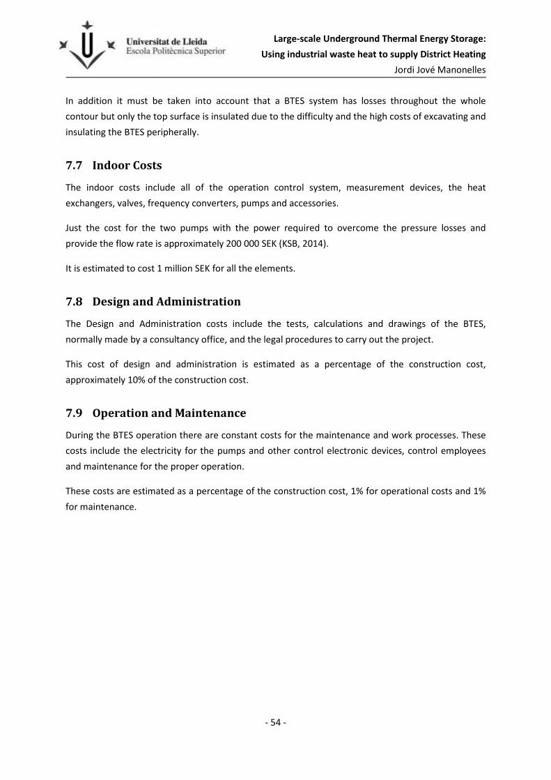
Large-scale Underground Thermal Energy Storage:
Using industrial waste heat to supply District Heating
Jordi Jové Manonelles
- 54 -
In addition it must be taken into account that a BTES system has losses throughout the whole
contour but only the top surface is insulated due to the difficulty and the high costs of excavating and
insulating the BTES peripherally.
7.7 Indoor Costs
The indoor costs include all of the operation control system, measurement devices, the heat
exchangers, valves, frequency converters, pumps and accessories.
Just the cost for the two pumps with the power required to overcome the pressure losses and
provide the flow rate is approximately 200 000 SEK (KSB, 2014).
It is estimated to cost 1 million SEK for all the elements.
7.8 Design and Administration
The Design and Administration costs include the tests, calculations and drawings of the BTES,
normally made by a consultancy office, and the legal procedures to carry out the project.
This cost of design and administration is estimated as a percentage of the construction cost,
approximately 10% of the construction cost.
7.9 Operation and Maintenance
During the BTES operation there are constant costs for the maintenance and work processes. These
costs include the electricity for the pumps and other control electronic devices, control employees
and maintenance for the proper operation.
These costs are estimated as a percentage of the construction cost, 1% for operational costs and 1%
for maintenance.

Large-scale Underground Thermal Energy Storage:
Using industrial waste heat to supply District Heating
Jordi Jové Manonelles
- 55 -
8 Results
In order to find the optimum features for the chosen model, different parameters and conditions
were set in multiple simulations with the program DST. Basically the boreholes spacing and depth are
the key of the storage shape, because varying these two parameters the number of boreholes,
storage surface and volume change as well.
The different BTES models used with the purpose to find the optimal solution for the Kronan heat
storage are shown in Table 14:
Table 14. Basic features of the BTES models studied.
Storage 1 Storage 2 Storage 3 Storage 4 Storage 5 Storage 6
Volume (m3) 1 366 000 1 372 000 1 379 000 1 386 000 1 246 000 1 251 000
Spacing (m) 5,00 5,00 5,00 5,00 4,75 4,75
Borehole depth (m) 175 200 225 250 175 200
Surface/borehole (m2) 25,00 25,00 25,00 25,00 22,56 22,56
Number of boreholes 312 274 245 222 316 277
Total surface (m2) 7806 6860 6129 5544 7120 6255
Storage 7 Storage 8 Storage 9 Storage 10 Storage 11 Storage 12
Volume (m3) 1 258 000 1 265 000 1 143 000 1 148 000 1 154 000 1 160 000
Spacing (m) 4,75 4,75 4,50 4,50 4,50 4,50
Borehole depth (m) 225 250 175 200 225 250
Surface/borehole (m2) 22,56 22,56 20,25 20,25 20,25 20,25
Number of boreholes 248 224 323 283 253 229
Total surface (m2) 5591 5060 6531 5740 5129 4640
Storage 13 Storage 14 Storage 15 Storage 16 Storage 17 Storage 18
Volume (m3) 1 048 000 1 052 000 1 058 000 1 063 000 963 000 967 000
Spacing (m) 4,25 4,25 4,25 4,25 4,00 4,00
Borehole depth (m) 175 200 225 250 175 200
Surface/bh(m2) 18,06 18,06 18,06 18,06 16,00 16,00
Num. of boreholes 332 291 260 235 344 302
Total surface (m2) 5989 5260 4702 4252 5503 4835
Storage 19 Storage 20 Storage 21 Storage 22 Storage 23 Storage 24
Volume (m3) 972 000 977 000 883 000 887 000 892 000 896 000
Spacing (m) 4,00 4,00 3,75 3,75 3,75 3,75
Borehole depth (m) 225 250 175 200 225 250
Surface/bh(m2) 16,00 16,00 14,06 14,06 14,06 14,06
Num. of boreholes 270 244 359 315 282 255
Total surface (m2) 4320 3908 5046 4435 3964 3584

Large-scale Underground Thermal Energy Storage:
Using industrial waste heat to supply District Heating
Jordi Jové Manonelles
- 56 -
8.1 Procedure and storage operation.
The procedure to compare the different models with the same criteria using DST is rather simple:
firstly the main characteristics are established and then the volume is increased until the BTES
extraction is able to fulfill the heating demand in the tenth year of operation. All the models have a
similar energetic profile (see Figure 28), the extraction since the third year is almost the maximum
needed for the whole neighborhood and then it increases slowly until it reaches the total demand.
The objective is to fulfill the total demand in the tenth year of operation because of the fact that all
the houses will not be occupied the first year, which means the heating demand will increase
gradually over the years until the neighborhood is totally filled. Although it should be highlighted that
all the simulated models are able to supply at least 95% of the total demand after the three first
years and after that the increase is slow until reaching the maximum in the tenth year.
As seen in Figure 28 this is the behavior of a BTES, despite the flow rate and the temperature for the
injection being constant the energy injection is very high at the beginning and then decreases slowly,
that is because the bedrock temperature in the storage volume and surroundings is colder in the first
years and increases easily. Simultaneously the energy losses decrease over the years, because at
startup the surrounding has to heat up, then when the temperature difference between the storage
volume and the surroundings decreases the losses are reduced proportionally.
0
5000
10000
15000
20000
25000
30000
35000
1 2 3 4 5 6 7 8 9 10
MWh
Year
BTES Energy behavior (storage7)
Injection
Extraction
Losses
Figure 28. Energy injection, extraction and losses evolution during 10 years in storage model 7.

Large-scale Underground Thermal Energy Storage:
Using industrial waste heat to supply District Heating
Jordi Jové Manonelles
- 57 -
Regarding the temperature behaviour, in Figure 29 can be seen how after three years of operation
the storage mean temperature (green line) reaches almost the same values, with a maximum of 60oC
at the end of summer and a minimum of 38oC at the end of winter. Meanwhile the temperature
injection, represented by a red line, has the values given by the user during the summer months (
Table 7). Then in the cold months, during extraction, the red line represents the value of the return
temperature coming back from the simulated district heating.
Finally, the blue line symbolizes the extraction temperature which in cold months (when it is
decreasing) represents the supplied temperature to the district heating. In this case the minimum
was established to not extract energy when it is below 35 degrees. For that reason in the first years
flat portions can be seen at the end of summer.
8.2 Spacing and depth
As mentioned earlier the two parameters that characterize the storage shape are the spacing
between boreholes and the borehole depth. Keeping the other parameters constant and varying
those two reveals how it affects the storage.
Table 15 shows how the borehole spacing influences the storage shape and its behaviour. Increasing
the separation between boreholes means that more volume is needed to store the same amount of
energy, but due to the larger volume fewer boreholes are needed. Also, increasing volume means a
bigger surface is in contact with the surroundings, which means larger heat losses. Steady-state heat
losses are shown in Table 15.
Figure 29. Evolution of injection, extraction and mean storage temperatures during 10 years in storage model 7.

Large-scale Underground Thermal Energy Storage:
Using industrial waste heat to supply District Heating
Jordi Jové Manonelles
- 58 -
The last column of the table represents the difference between the maximum and minimum storage
mean temperature during one year, the values are given from the tenth year when the storage is
highly stable. As equation ( 1 ) indicates to store the same amount of energy, when the storage
volume decreases the temperature difference must increase and that is shown in the table as well.
Therefore when a BTES system needs to supply higher temperatures it is easier with a smaller
storage, i.e. decreasing the borehole spacing.
Table 15. Results as a function of the borehole spacing.
Borehole
Spacing (m)
Average
Volume (m3)
Average No
boreholes
Average Losses
(MWh/annual)
Average Temp.
Difference (oC)
5 1 375 750 263 3 603 19,1
4,75 1 255 000 266 3 490 20,7
4,5 1 151 250 272 3 401 22,4
4,25 1 055 250 280 3 321 24,3
4 969 750 290 3 253 26,3
3,75 889 500 303 3 184 28,5
Table 16 shows how the borehole depth influences the results. As seen in the first column the depth
is not significant for the storage volume, with boreholes 75 meters deeper the storage barely
increases 2%, which indicates a bigger surface is needed when the depth is lowered. At the same
time when a larger surface is required the number of boreholes increases, e.g. if the borehole depth
is increased from 175m to 200m the number of boreholes required can be reduced by 40, but the
savings are also reduced with increased depth.
Regarding the steady-state heat losses, the deeper the storage the less it follows the ideal shape, the
cubic one. This explains why the heat storage loss is higher the deeper it is.
Meanwhile the temperature difference does not change in function of depth, as said before it
depends on the storage volume following equation ( 1 ), since the volume does not change at all the
temperature difference behaves constantly.
Table 16. Results in function of the borehole depth.
Borehole
depth (m)
Average
Volume (m3)
Average No
boreholes
Average Losses
(MWh/annual)
Average Temp.
Difference (oC)
175 1 108 167 331 3 205 23,6
200 1 112 833 291 3 308 23,6
225 1 118 833 260 3 430 23,5
250 1 124 500 235 3 558 23,5

Large-scale Underground Thermal Energy Storage:
Using industrial waste heat to supply District Heating
Jordi Jové Manonelles
- 59 -
8.3 Storage design as a function of cost
The parameters of the optimum storage depend on the injection energy price, as mentioned above
the higher the injection energy price, the lower the energy losses have to be in order for it to be
more profitable.
8.3.1 Low energy cost
The energy provided to charge the storage during the summer is waste heat coming from the steel
plant (see section 5.3). This waste heat is currently dumped into the bay, which means there is no
profit gained. For that reason there is the possibility to charge the storage with a very cheap energy.
The cost to provide the energy would be just for the electricity consumption of pumps, plus a few
benefits for the company.
In that situation a cost of 0,03 SEK/kWh is assumed and in Figure 30 the Annual Storage Cost is
represented for different storage models.
Figure 30. Annual Storage Cost for the different models with low energy price.
The graph shows that deeper boreholes mean cheaper storages. Furthermore, the costs are higher
when the borehole spacing is less due to more boreholes being needed, although if it is too wide it
gets expensive as well, because more surface and insulation is needed and there are more heat
losses.
So here, the optimum storage is number 8, and it should be noted that the spacing of 4,75 meters is
wider than what is usually used in large-scale BTES systems. In Table 17 the most outstanding results
are shown, including economical.
3 400 000
3 500 000
3 600 000
3 700 000
3 800 000
3 900 000
4 000 000
3,5 4 4,5 5
Annual Storage Cost
(SEK)
Borehole Spacing (m)
Energy price: 0,03 SEK/kWh
depth 175m
depth 200m
depth 225m
depth 250m

Large-scale Underground Thermal Energy Storage:
Using industrial waste heat to supply District Heating
Jordi Jové Manonelles
- 60 -
All the results of storage model 8 obtained with DST are shown in Appendix C.
Table 17. Results of storage model 8.
Year Injection
(MWh)
Extraction
(MWh)
Losses
(MWh) Efficiency Cas (SEK)
Cost kWh
(SEK/kWh)
Income
(SEK)
1 35616 5872 6978 16,5% 3 438 375 0,586 2 706 992
2 20990 12641 6440 60,2% 3 438 375 0,272 5 966 552
3 19548 13554 5439 69,3% 3 438 375 0,254 6 546 582
4 19077 13859 4871 72,6% 3 438 375 0,248 6 846 346
5 18785 13997 4508 74,5% 3 438 375 0,246 7 068 485
6 18559 14069 4254 75,8% 3 438 375 0,244 7 259 604
7 18372 14112 4060 76,8% 3 438 375 0,244 7 437 024
8 18215 14137 3905 77,6% 3 438 375 0,243 7 605 706
9 18082 14150 3779 78,3% 3 438 375 0,243 7 768 350
10 17965 14154 3672 78,8% 3 438 375 0,243 7 926 240
TOTAL 205 209 130 545 47 906 63,6% 34 383 749 0,263 67 131 881
As commented above in section 8.1 the energy injection at the beginning warms up the storage and
the surroundings and for that reason the heat losses are pretty high, but over the years the heat loss
decreases and the efficiency increases. As mentioned in section 4.10, the storage life cycle has no
specific limitation and the total efficiency shown in the last row will continue improving over the
years.
The kWh Cost represents the price of the energy extraction considering the Annual Storage Cost.
Since the storage cost, slightly higher than 34 MSEK, is paid off in ten years, afterwards the cost of
kWh will decrease to 0,07SEK because the costs for each year will be only for operation, maintenance
and heat loss (approximately 1MSEK/year). Hence the benefits (incomes - annual cost) will increase
to 7 MEK/year.
The last column represents the incomes earned by selling the energy extracted from the storage, in
the price of this energy the injection costs are subtracted and the energy price evolution is also
considered. Thus, to calculate the profits subtract the Annual Storage Cost from the income.
The payback of the BTES takes 6,72 years, which is very good considering the long term benefits.
8.3.2 Medium Energy cost
Another possibility is if the energy company wants to benefit from selling this waste heat, which
would be the most expected situation. In order to simulate this circumstances an energy injection
cost of 0,15 SEK/kWh is assumed.

Large-scale Underground Thermal Energy Storage:
Using industrial waste heat to supply District Heating
Jordi Jové Manonelles
- 61 -
As seen in Figure 31, the cost curves get closer when the price is increased. On one hand the overall
result is similar to the first, but approximately 600 000 SEK/year more expensive. On the other hand
the optimal storage is not the same, because in that case the model number 12 with shorter
borehole spacing, 4,5 meters, would be best. This proves when the energy price increases it becomes
more important to reduce the heat loss and one way to do it is by reducing the borehole spacing.
It should be noted that the difference between the optimal borehole spacing and ±0,5 meters is less
than 70000 SEK per year, which means barely 2%.
Figure 31.Annual Storage Cost for the different models with medium energy price.
All the results of storage model 12 obtained with DST are shown in Appendix D.
In the following table (Table 18) the most important results for the optimal storage (model 12) are
shown.
Table 18. Results of storage model 12,
Year Injection
(MWh)
Extraction
(MWh)
Losses
(MWh) Efficiency Cas (SEK)
Cost kWh
(SEK/kWh)
Incomes
(SEK)
1 34950 6966 7031 0,20 4 048 019 0,581 2 375 406
2 20589 12771 6317 0,62 4 048 019 0,317 4 495 392
3 19327 13580 5306 0,70 4 048 019 0,298 4 929 540
4 18905 13870 4748 0,73 4 048 019 0,292 5 187 380
5 18637 14010 4396 0,75 4 048 019 0,289 5 393 850
6 18431 14080 4147 0,76 4 048 019 0,288 5 575 680
3 900 000
4 000 000
4 100 000
4 200 000
4 300 000
4 400 000
4 500 000
3,5 4 4,5 5
Annual Storage Cost
(SEK)
Borehole Spacing (m)
Energy price: 0,15 SEK/kWh
depth 175m
depth 200m
depth 225m
depth 250m

Large-scale Underground Thermal Energy Storage:
Using industrial waste heat to supply District Heating
Jordi Jové Manonelles
- 62 -
7 18256 14118 3959 0,77 4 048 019 0,287 5 746 026
8 18106 14139 3809 0,78 4 048 019 0,286 5 910 102
9 17975 14149 3686 0,79 4 048 019 0,286 6 069 921
10 17861 14154 3582 0,79 4 048 019 0,286 6 227 760
TOTAL 203 037 131 837 46 981 0,65 40 480 194 0,307 51 911 057
As in the first case the energy efficiency improves over the years but after ten years it becomes
almost stable. There is 1 GWh less in total heat losses but the higher number of boreholes and the
increased energy price make the storage cost 40,5 MSEK.
After the tenth year the Annual Storage Cost including operation, maintenance and heat loss is 1
MSEK which means a price for each kilowatt of 0,069 SEK. Thus the profits after the storage
investment is paid off are 5,2MSEK per year.
The payback of this BTES takes 9,14 years, which is still good for this kind of project.
8.3.3 High energy cost
The last supposition is if the energy injection is provided by an expensive heat source, e.g. solar
collectors. In this situation the energy price represents the costs of buying and installing the
collectors and the pipe network. For this situation an injection energy cost of 0,35 SEK/kWh is
assumed, which means a cost of 45 MSEK for the solar collectors.
Figure 32. Annual Storage Cost for the different models with high energy price.
5 050 000
5 150 000
5 250 000
5 350 000
5 450 000
5 550 000
5 650 000
3,5 4 4,5 5
Annual Storage Cost
(SEK)
Borehole Spacing (m)
Energy price: 0,35 SEK/kWh
depth 175m
depth 200m
depth 225m
depth 250m

Large-scale Underground Thermal Energy Storage:
Using industrial waste heat to supply District Heating
Jordi Jové Manonelles
- 63 -
In this case the optimum storage is storage model 16 with a borehole spacing of 4,25 meters and the
same depth as the other situations, 250 meters.
Table 19. Results of storage model 16.
Year Injection
(MWh)
Extraction
(MWh)
Losses
(MWh) Efficiency Cas SEK
Cost kWh
(SEK/kWh)
Incomes
(SEK)
1 34325 7940 7122 0,23 5 052 914 0,636 1 119 540
2 20220 12892 6196 0,64 5 052 914 0,392 1 959 584
3 19139 13607 5183 0,71 5 052 914 0,371 2 217 941
4 18756 13881 4639 0,74 5 052 914 0,364 2 415 294
5 18507 14018 4296 0,76 5 052 914 0,360 2 593 330
6 18314 14090 4054 0,77 5 052 914 0,359 2 761 640
7 18151 14124 3870 0,78 5 052 914 0,358 2 923 668
8 18006 14140 3724 0,79 5 052 914 0,357 3 082 520
9 17878 14149 3604 0,79 5 052 914 0,357 3 240 121
10 17767 14154 3503 0,80 5 052 914 0,357 3 396 960
11 17767 14154 3503 0,80 1 069 714 0,076 8 506 554
12 17767 14154 3503 0,80 1 069 714 0,076 8 662 248
13 17767 14154 3503 0,80 1 069 714 0,076 8 817 942
14 17767 14154 3503 0,80 1 069 714 0,076 8 973 636
TOTAL 272 131 189 611 60 203 0,70 50 529 140 0,266 60 670 978
As seen in Table 19 the cost of extracted heat is not profitable until the tenth year because the sum
of the cost of extracted and injected heat is greater than the selling price in winter. Then, when the
Total Storage Investment Cost is paid off the incomes are much higher, because from the tenth year
the cost is just for the maintenance, operation and heat loss plus 100 000 SEK, a value assumed as a
maintenance and operation cost for the solar collectors installation, in total 1,1MSEK/year.
In that case the payback is 13 years and then the benefits are approximately 8 MSEK per year after
fourteen years. In addition the lifetime of the solar collectors should be considered because it is
shorter than that of the storage, which means in approximately 30 years, depending on the type of
collectors, they must be replaced by new ones which will involve another future investment.
Summarizing from the three different energy costs, while the injection energy price is not higher
than 0,45 SEK/kWh the models with 250 meters of boreholes depth are the best option. If it reaches
a very expensive price, as seen in Figure 33, then the optimum depth and spacing become shorter,
but curiously the 175 m of borehole depth is still the worse choice. In this case a depth of 200 m and
spacing of 4,25m are the optimal parameters.

Large-scale Underground Thermal Energy Storage:
Using industrial waste heat to supply District Heating
Jordi Jové Manonelles
- 64 -
Figure 33. Annual Storage Cost for the different models with expensive price.
As seen in the figures 25 to 28 the higher the energy price the closer the lines of the different models
annual cost, which reduces the importance of finding the optimal parameters.
In the previous four graphs there is the same difference between the maximum and the minimum
value in the vertical axis to better see the cost curves evolution.
8.4 Thermal Insulation
As is mentioned above the heat losses have a greater influence with increasing energy price. The
factor that can reduce the heat loss is the thermal insulation, but it should be investigated how
profitable and helpful it is. In order to evaluate whether the insulation is profitable two different
situations are tested.
These two cases are when the energy price is medium (0,15 SEK/kWh) and expensive (0,35
SEK/kWh). In both situations a borehole depth of 250 meters is used, because as seen before it is the
best choice.
Figure 16 shows the cases studied for the different storage models. It should be remembered that a
soil layer of 10 meters is above the bedrock and the following insulation layers would start at the
ground surface level.
The option A is the one used in the simulations above. It is a cheap material with a conductivity ten
times lower than the soil. The option B is without any specific insulation material, just leaving 1
meter of soil above the boreholes. Option C tests a very good insulation material which is quite
expensive. The layers A and C have a thickness of 0,4 and 0,5 respectively, and are not too wide to
6 000 000
6 100 000
6 200 000
6 300 000
6 400 000
6 500 000
6 600 000
3,5 4 4,5 5
Annual Storage Cost
(SEK)
Borehole Spacing (m)
Energy price: 0,6 SEK/kWh
depth 175m
depth 200m
depth 225m
depth 250m

Large-scale Underground Thermal Energy Storage:
Using industrial waste heat to supply District Heating
Jordi Jové Manonelles
- 65 -
avoid irrational costs with land movements and insulation, while option B (the soil) has a thicker
layer which means more land movement costs but no insulation costs.
Table 20. Different insulations
A B C
Material Foam glass No (soil) Polyfoam C 4 LJ 1250
Thermal Conductivity (W/m,K) 0,13 1,4 0,036
Insulation Layer (m) 0,4 1 0,5
Price (SEK/m3) 534 0 1725
Average Loss through the top (%) 4,3 17 2,4
Average Number of boreholes 235 241 234
As seen in the table the percentage of energy loss through the top is reduced considerably by using
an insulation material, as A and C columns. Also, due to the reduction of heat loss less volume is
needed to store the same amount of energy, which implies the number of boreholes decreases.
Despite the conductivity of material C is almost four times lower, the number of boreholes barely
changes.
Figure 34 shows the Annual Storage Costs if the price of the energy injection is 0,15 SEK/kWh, which
is the price expected approximately for the waste heat. On one hand it is clear that using the
expensive material (option C) is not worthwhile, it is surprisingly worse than let a soil layer of 1 meter
without insulation material, option B, the difference between them is 385 000 SEK/year. On the
other hand, the difference between using a cheaper insulation material and only the soil is not very
important, an average of 76 800 SEK/year.
Figure 34. Annual Storage costs with different insulation layers. Data: Energy price 0,15 SEK/kWh; λA=0,13 W/m,K, λB= 1,4
W/m,K and λC=0,036W/m,K; thickness: zA=0,4m, zB=1m, zC=0,5m
4 000 000
4 100 000
4 200 000
4 300 000
4 400 000
4 500 000
4 600 000
4 700 000
3,50 4,00 4,50 5,00
Annual Storage
Costs (SEK)
Spacing (m)
Different insulations, energy price 0,15 SEK/kWh
Insulation A
Insulation B
Insulation C
Large-scale Underground Thermal Energy Storage:
Using industrial waste heat to supply District Heating
Jordi Jové Manonelles
- 66 -
In the following graph (Figure 35) a higher price, 0,35 SEK/kWh, is considered. The results show a
greater separation between the curves A and B, which means the insulation is becoming more
important, proved also by the closer distance to the curve C. Nevertheless the expensive insulation
material is by far not profitable to use. The average money saved using option A respect B and C is
200 000 and 445 000 SEK/year.
Figure 35. Annual Storage costs with different insulation layers. Data: Energy price 0,35 SEK/kWh; λA=0,13 W/m,K, λB= 1,4
W/m,K and λC=0,036W/m,K; thickness: zA=0,4m, zB=1m, zC=0,5m.
In the last two charts the expectations are confirmed: logically, the cheaper the injection energy the
narrower the separation between curves A and B, because the cost of the heat loss becomes less
significant. Moreover it is not worth using a very good insulation material even if the injection energy
price is very high.
8.5 Sensitivity Analysis
With the purpose of analyzing how conditions different from those previously established would
affect the optimal BTES model a sensitivity analysis is made. However only the most transcendental
parameters are varied and tested, namely the bedrock thermal conductivity and volumetric heat
capacity.
In the hypothetical and expected case where the injection energy price is around 0,15 SEK/kWh the
optimal model for this situation is used as a reference, i.e. model 12 (see section 8.3.2).
8.5.1 Bedrock Thermal conductivity
Depending on the bedrock material the thermal properties are different. Table 21 shows how the
model varies if the thermal conductivity value is 10% higher or lower than expected.
5 000 000
5 100 000
5 200 000
5 300 000
5 400 000
5 500 000
5 600 000
5 700 000
5 800 000
3,50 4,00 4,50 5,00
Annual Storage
Costs (SEK)
Spacing (m)
Different insulations, energy price 0,35 SEK/kWh
Insulation A
Insulation B
Insulation C

Large-scale Underground Thermal Energy Storage:
Using industrial waste heat to supply District Heating
Jordi Jové Manonelles
- 67 -
Table 21. Results with different bedrock thermal conductivity.
+10% Storage 12 -10%
Thermal conductivity (W/m,K) 3,80 3,45 3,11
Volume (m3) 1 120 000 1 160 000 1 209 000
Number of boreholes 221 229 239
Energy efficiency (%) 78,40 79,25 80,10
Annual Steady Heat Loss (MWh) 3 768 3 582 3 401
Annual Storage Cost 3 977 115 4 048 019 4 143 671
With a higher thermal conductivity value there is a higher heat transfer rate, which means it is easier
to heat up a material. For this reason the volume needed is lower but at the same time causes
greater heat loss. Conversely, with a lower value the losses are smaller and there is a better
efficiency, but the fact that it needs a greater volume, i.e. more boreholes, causes its annual costs to
be higher. It is important to remember the annual storage cost is the money that is to be paid each
year for a decade, to pay off the storage.
8.5.2 Bedrock Volumetric Heat capacity
Also depending on the bedrock material the density and specific heat could be different, multiplying
both material properties the volumetric heat capacity is obtained. Table 22 shows how the results
are influenced if this thermal property is 10% higher or lower.
Table 22. Results with different bedrock volumetric heat capacity.
+10% Storage 12 -10%
Volumetric heat capacity (J/m3,K) 1,94E+06 2,16E+06 2,38E+06
Volume (m3) 1 127 000 1 160 000 1 201 000
Number of boreholes 223 229 237
Energy efficiency (%) 79,10 79,20 79,40
Annual Steady Heat Loss (MWh) 3 608 3 582 3 557
Annual Storage Cost 3 963 574 4 048 019 4 154 253
On one hand, as seen in table the volumetric heat capacity has less influence on the storage results,
but it has a bigger impact in the annual costs because of the combination of the results variation.
On the other hand, when the capacity to store energy in a certain volume is increased less volume is
needed and reduces the annual storage cost.
Despite having fewer losses with a lower volumetric heat capacity and thus being more efficient, the
fact that makes the storage more expensive is a bigger volume, which implies more boreholes and
more expensive construction costs.

Large-scale Underground Thermal Energy Storage:
Using industrial waste heat to supply District Heating
Jordi Jové Manonelles
- 68 -
8.6 Possible Distribution.
Figure 36 shows a possible distribution with an estimated distance of 50 meters to the machinery
hut. It is the optimum storage, the model number 12, with 229 boreholes distributed in 15 horizontal
rows. Also appears the culvert and manifold diameters.
Figure 36. System distribution: pipes and boreholes. (optimum storage: model 12)

Large-scale Underground Thermal Energy Storage:
Using industrial waste heat to supply District Heating
Jordi Jové Manonelles
- 69 -
9 Conclusions
The significance of the studies in the energy storage field is unquestionable due to the importance of
reducing the world energy consumption and fortifying renewable energy.
In a project of this size, handling a large amount of energy, is of utmost importance and for a
seasonal storage no better options are available than BTES. The main points are the system efficiency
and the payback between 7 and 9 years.
The efficiency (heat recovery) of the BTES is higher than 75% after the fifth year of operation
reaching 80% in the tenth year, which means a great ratio of use.
Economically, all the factors influence the storage shape, and all results depend on the injection
energy price. A good deal with the energy company would mean an important reduction in the total
cost. Most likely the probable cost for the energy will be the one termed “medium price” in the
project. Considering that price, 0,15 SEK/kWh, the Annual Cost of the Storage is 4 MSEK during ten
years, after which the storage is paid off and the annual cost is reduced to 1 MSEK for maintenance
and operation. The total cost of the storage is 40 MSEK.
In the case of the heat source being solar energy, the price of the solar collectors would replace the
cost of energy injection. However the injection for the first year must be done with waste heat
because in the first year the efficiency of the BTES is below 50% and it needs more than 30 GWh,
while the solar system should be planned to supply about 18GWh/year, the annual heat demand.
Although increasing the borehole depth over 150 meters means the storage shape is far from the
theoretical optimum shape to reduce the heat loss (cubic), it has been proved that in all cases a
depth of 250 meters is better from an economic point of view. Deeper distances should be studied
because there are no prices and results on large-scale systems up to now.
It should be noted that the drilling cost function is only valid for a certain limited depth, because the
drilling cost is not clear beyond 250 meters. Although the deeper the boreholes the fewer holes are
needed, which means it is profitable to continue drilling until the cost reaches the same value as
starting a new hole.
The borehole spacing is a most important parameter and it strongly influences the storage shape. It is
a little bit higher than expected for the low injection energy cost, being the optimum 4,75 meters.
But when the energy cost is higher the optimum borehole spacing gets reduced to 4,25 meters, that
is due to the cost of the heat loss. Therefore using a borehole spacing 0,5 meters wider or shorter
than the optimum is barely 50 000 SEK/year more expensive. This means that it is possible to play
with the parameters to affect other objectives with only slightly increasing the cost.
Large-scale Underground Thermal Energy Storage:
Using industrial waste heat to supply District Heating
Jordi Jové Manonelles
- 70 -
The importance of the thermal insulation depends on the energy price, but it is not profitable to
spend a large amount of money in insulation because the biggest percentage of heat loss is through
the storage sides and in to a lesser degree through the bottom. Moreover, the soil layer thickness
above the bedrock decreases the heat loss and the necessity to have an insulation layer.
Regarding the bedrock thermal conductivity, the higher it is, the less rock volume (also number of
boreholes) is needed and the cost will thus be lower, but it also means a greater heat loss.
Recommendations
The procedure to arrange the BTES in Kronan should follow these recommendations:
Carry out a study of the steel market and analyze the reliability of the steel plant to be confident that
their production will not be significantly reduced in the following years. If it is not reliable analyze
and discuss other heat sources such as solar energy or waste heat from other processes.
Start with the TRT-test in all the area available to find the best location following the next steps:
- Good bedrock thermal properties.
- Thin soil layer because the soil drilling costs are twice the rock drilling.
- Soil layer with high thermal conductivity: to decrease the losses on the top of the storage.
- Bedrock with high thermal conductivity: as said above it improves the injection and
extraction, so the volume and the number of boreholes may be decreased, which would
reduce the main cost, the drilling.
- Regarding the borehole filling material consider using a high solids grout to improve the
thermal conductivity.

Large-scale Underground Thermal Energy Storage:
Using industrial waste heat to supply District Heating
Jordi Jové Manonelles
- 71 -
10 References
Andersson, O. (2007). Aquifer Thermal Energy Storage. i H. Ö. Paksoy, Thermal Energy Storage for
Sustainable Energy Consumption (ss. 155-177). Adana (Turkey): NATO Science Series.
Andersson, O., & Leif, R. (2012). The HT-BTES plant at Xylem in Emmaboda, Sweden - Experiences
from design, construction and initial operation.
Cengel, Y. (2002). Heat Transfer. A Practical Approach. Reno(USA): McGraw-Hill.
Dincer, I., & Rosen, M. (2011). Thermal Energy Storage: systems and applications. New York: Wiley.
Dinser, I., & Rosen, M. (2011). Thermal Energy Storage: Systems and Applications. Hoboken(USA):
Wiley.
Drake Landing Solar Comunity. (2014). Drake Landing Solar Comunity. Hämtat från
http://www.dlsc.ca/
Elfgren, E., Grip, C., Wang, C., & Karlsson, J. (2010). Possibility to Combine Exergy with other Process
Integration Methods for a Steelmaking Case. CHEMICAL ENGINEERING TRANSACTIONS
Volume 21.
Ericsson, L. (1985). Heat Exchange Between Crystallyne Bedrock and Borehole in an Energy Well
System. Göteborg (Sweden): Department of Geology, Chalmers University of Technology and
University of Göteborg.
Gehlin, S. (2002). Thermal Response Test. Method Development and Evaluation. (Doctoral thesis).
Luleå: Department of Environmetal Engineering. Division of Water Resources Engineering.
Gustafsson, A. (2010). Thermal Response Test- influence of conflective flow in groundwater filled
borehole heat exchangers. (Doctoral thesis). Luleå: Luleå Tekniska Universitet. Division of
Architecture and Infrasctructure. .
Hammerschlag, R., & Schaber, C. (2007). Handbook of Energy Efficiency and Renewable Energies. CRC
Press.
Hellström, G. (1989). Duct Ground Heat Storage Model. Manual for computer code. Lund: University
of Lund.
Hellström, G. (2013). UTES Experiences from Sweden. Lund University: NeoEnergy Sweden Ltd.
Hellström, G., & Sanner, B. (2000). Earth Energy Designer 2.0. BLOCON.
Hughes, V. (2014). Waste Heat Is Free Energy. So Why Aren't We Using It? Popular Science.
KSB, P. a. (2014). KSB - Pumps,Valves and Service. Hämtat från http://www.ksb.com/

Large-scale Underground Thermal Energy Storage:
Using industrial waste heat to supply District Heating
Jordi Jové Manonelles
- 72 -
Larsson, S. (2013). Statistika Meddelanden. Luleå Kommun.
Luleå Kommun. (2014). Luleå Kommun. Hämtat från http://www.lulea.se/
Nordell, B. (1994). Borehole Heat Store Design Optimitzation. Doctoral thesis. Luleå: Luleå University
of Technology, Water Resource Engineering.
Nordell, B. (2000). Large-scale thermal energy storage. Luleå, Sweden: WinterCities’2000, Energy and
Environment.
Nordell, B. (2012). Underground Thermal Energy Storage (UTES). Innostock 2012. The 12th
International Conference on Energy Storage. Lleida: Innostock.
Pahud, D., & Hellström, G. (1996). The New Duct Ground Heat Model for TRNSYS. Physical Models for
Thermal Energy Stores (ss. 127-136). Eindhoven: Eurotherm.
Public Radio International. (2014). Public Radio Internationa (www.pri.org). Hämtat från Science,
Tech Environment: http://www.pri.org/stories/2012-06-26/sweden-imports-waste-
european-neighbors-fuel-waste-energy-program
Sang Lee, K. (2013). Underground Thermal Energy Storage. Springer.
Skogsberg, K. (2014). Snowpower. Hämtat från www.snowpower.se
Sundberg, J. (1988). Thermal Properties od Soils and Rocks. Göteborg (Sweden): Geoliska
Institutionen.
Sveriges Geologiska Undersökning. (2014). Sveriges Geologiska Undersökning-Geological Survey of
Sweden. Hämtat från http://www.sgu.se/sgu/eng/index.html
SWECO. (u.d.). SWECO. Hämtat från SWECO. Sustainable engineering and design.:
http://www.swecogroup.com/ 2014
The Engineering ToolBox. (2014). The Engineering ToolBox. Hämtat från
http://www.engineeringtoolbox.com/
The Living Planet. (2012). The Living Planet. Biodiversity, biocapacity and better choices. WWF.
Underground Energy LLC. (2014). Underground Energy, Applied Hydrogeology Geothermal
Innovation. Hämtat från http://www.underground-energy.com/

Large-scale Underground Thermal Energy Storage:
Using industrial waste heat to supply District Heating
Jordi Jové Manonelles
- 73 -
11 Appendices
A. Heating demand calculation.
B. Different model simulations: basic parameters and costs.
C. Results storage model 8.
D. Results storage model 12.
E. Results storage model 16.
F. Pressure drop calculations.

Large-scale Underground Thermal Energy Storage:
Using industrial waste heat to supply District Heating
Jordi Jové Manonelles
- 74 -
A. Heating demand calculation
The calculation for the heating demand is made on an hourly basis and due to the long extension
(more than 8765 rows) it is not added in this project, but it is attached as Excel file called “Kronan,
heat demand.xls” on the project CD-ROM. In Table 23 an example is shown for one day.
Table 23. Heating demand for the first day of January.
Date Hour T,air [
oC]
Heat-degree-days [
oC,h]
E,heating [kWh/h]
E,dhw [kWh/h]
E,total [kWh/h]
01/Jan 0-1 0.3 16.7 1.4 0.0 1.4 01/Jan 1-2 -0.2 17.2 1.4 0.0 1.4 01/Jan 2-3 -0.5 17.5 1.4 0.0 1.4 01/Jan 3-4 -1.0 18.0 1.5 0.0 1.5 01/Jan 4-5 -1.4 18.4 1.5 0.1 1.6 01/Jan 5-6 -1.5 18.5 1.5 0.4 1.9 01/Jan 6-7 -2.1 19.1 1.6 1.1 2.7 01/Jan 7-8 -2.7 19.7 1.6 0.4 2.0 01/Jan 8-9 -2.9 19.9 1.6 0.2 1.8 01/Jan 9-10 -3.2 20.2 1.7 0.2 1.8 01/Jan 10-11 -3.0 20.0 1.6 0.3 1.9 01/Jan 11-12 -2.9 19.9 1.6 0.4 2.1 01/Jan 12-13 -2.8 19.8 1.6 0.4 2.0 01/Jan 13-14 -2.7 19.7 1.6 0.3 1.9 01/Jan 14-15 -2.8 19.8 1.6 0.3 1.9 01/Jan 15-16 -1.2 18.2 1.5 0.4 1.9 01/Jan 16-17 -0.8 17.8 1.5 0.6 2.0 01/Jan 17-18 -0.5 17.5 1.4 1.2 2.6 01/Jan 18-19 -0.2 17.2 1.4 2.1 3.5 01/Jan 19-20 -0.3 17.3 1.4 1.2 2.6 01/Jan 20-21 -0.3 17.3 1.4 0.4 1.8 01/Jan 21-22 -0.5 17.5 1.4 0.1 1.5 01/Jan 22-23 -0.7 17.7 1.5 0.0 1.5 01/Jan 23-24 -0.3 17.3 1.4 0.0 1.4
The three first columns are easy to understand, the fourth represents the difference between the
ambient temperature and the limit temperature when the heat must be supplied, in this case 17
degrees.
Large-scale Underground Thermal Energy Storage:
Using industrial waste heat to supply District Heating
Jordi Jové Manonelles
- 75 -
In the calculations for the space heating and district hot water energy the values are estimated
proportionally to the total energy consumed by a new house in Luleå. These values are the following:
Table 24. Energy consumption for a single house in Luleå.
Data
Total Space Heating Energy 8,400 kWh/year
23,01 kWh/day
Total District Hot Water Energy 3,600 kWh/year
9,9 kWh/day
Then the heating energy for each hour is calculated multiplying the ratio of the degrees difference
over the total degrees difference for the whole year per space heating total energy that appears in
Table 24.
The district hot water calculation is also used a proportion of the total value, but in this case the daily
average of consumption on an hourly basis is known, as shown in Table 25.
Table 25. Daily percentage of district hot water consumption in Luleå.
h % dhw
0-1 0.0 % 1-2 0.0 % 2-3 0.0 % 3-4 0.0 % 4-5 0.8 % 5-6 3.8 % 6-7 11.4 % 7-8 3.8 % 8-9 1.9 %
9-10 1.9 % 10-11 3.0 % 11-12 4.5 % 12-13 3.8 % 13-14 3.0 % 14-15 3.0 % 15-16 3.8 % 16-17 5.7 % 17-18 12.1 % 18-19 21.2 % 19-20 11.7 % 20-21 3.8 % 21-22 0.8 % 22-23 0.0 % 23-24 0.0 %
The data is given by Kjell Skogsberg from the company Snowpower.

Large-scale Underground Thermal Energy Storage:
Using industrial waste heat to supply District Heating
Jordi Jové Manonelles
- 76 -
As explained before in section 5.2, during the warmer months the storage is only charging and the
heating demand would be directly supplied from the heat source and thus the electricity
consumption for the heat pumps is subtracted from the total heat demand for the BTES. Thereby the
heating demand is summarized in Table 26.
Table 26. Energy demand for the 1500 houses and the energy supplied by the BTES.
Month E. space heating [MWh/month]
E dhw heating [MWh/month]
E. dhw electricity [MWh/month]
Total Energy [MWh/month]
BTES Heat Demand [MWh]
January 2 418 344 115 2 877 2 762
February 2 489 311 104 2 903 2 799
March 1 655 344 115 2 113 1 999
April 810 333 111 1 254 1 143
May 321 344 115 780 0
June 25 333 111 469 0
July 4 344 115 463 0
August 73 344 115 531 0
September 377 333 111 821 0
October 806 344 115 1 264 1 150
November 1 906 333 111 2 350 2 239
December 1 718 344 115 2 177 2 062
TOTAL 12 600 4 050 1 350 18 000 14 153

Large-scale Underground Thermal Energy Storage:
Using industrial waste heat to supply District Heating
Jordi Jové Manonelles
- 77 -
B. Storage models: parameters and costs
The results shown in the following tables are the characteristics of each BTES model and the capital
cost to build it.
Table 27. Parameters and costs of storage models 1 to 4.
Storage
Model 1
Storage
Model 2
Storage
Model 3
Storage
Model 4
Volume (m3) 1 366 000 1 372 000 1 379 000 1 386 000
Spacing (m) 5,00 5,00 5,00 5,00
Borehole depth (m) 175 200 225 250
Surface/borehole (m2) 25,00 25,00 25,00 25,00
Number of boreholes 312 274 245 222
Total surface (m2) 7806 6860 6129 5544
Flow (m3/s) 0,2 0,2 0,2 0,2
Flow x borehole (l/s) 0,64 0,73 0,82 0,90
Steady heat loss (MWh) 3 437 3 536 3 655 3 782
Transient heat loss (MWh) 9 770 10 291 10 769 11 225
COSTS
Cost drilling+piping (kr) 18 848 792 18 080 922 17 569 369 17 173 007
Insulation cost (kr) 1 876 494 1 649 144 1 473 385 1 332 778
Land movements cost (kr) 858 629 754 600 674 178 609 840
Pumps+HE+valves+control 1 000 000 1 000 000 1 000 000 1 000 000
Design and admin. Cost (SEK) 2 258 391 2 148 467 2 071 693 2 011 562
CONTRUCTION COST 24 842 306 23 633 133 22 788 625 22 127 187
Transient heat losses cost (SEK)
1 465 500 1 543 650 1 615 350 1 683 750
TOTAL INVESTMENT COST 26 307 806 25 176 783 24 403 975 23 810 937
Maintenance (SEK) 248 423 236 331 227 886 221 272
Operation (SEK) 248 423 236 331 227 886 221 272
Steady heat losses cost (SEK) 515 550 530 400 548 250 567 300
Annual Storage Cost (10years) 4 419 377 4 263 571 4 164 449 4 093 469
TOTAL COST 10 years 44 193 773 42 635 712 41 644 489 40 934 690

Large-scale Underground Thermal Energy Storage:
Using industrial waste heat to supply District Heating
Jordi Jové Manonelles
- 78 -
Table 28. Parameters and costs of storage models 5 to 8.
Storage
Model 5
Storage
Model 6
Storage
Model 7
Storage
Model 8
Volume (m3) 1 246 000 1 251 000 1 258 000 1 265 000
Spacing (m) 4,75 4,75 4,75 4,75
Borehole depth (m) 175 200 225 250
Surface/borehole (m2) 22,56 22,56 22,56 22,56
Number of boreholes 316 277 248 224
Total surface (m2) 7120 6255 5591 5060
Flow (m3/s) 0,2 0,2 0,2 0,2
Flow x borehole (l/s) 0,63 0,72 0,81 0,89
Steady heat loss (MWh) 3 322 3 422 3 544 3 672
Transient heat loss (MWh) 9 448 10 242 10 726 11 186
COSTS
Cost drilling+piping (kr) 18 816 367 18 061 759 17 575 384 17 200 556
Insulation cost (kr) 1 711 648 1 503 702 1 344 103 1 216 424
Land movements cost (kr) 783 200 688 050 615 022 556 600
Pumps+HE+valves+control 1 000 000 1 000 000 1 000 000 1 000 000
Design and admin. Cost (SEK) 2 231 121 2 125 351 2 053 451 1 997 358
CONTRUCTION COST 24 542 336 23 378 862 22 587 960 21 970 938
Transient heat losses cost (SEK)
1 417 200 1 536 300 1 608 900 1 677 900
TOTAL INVESTMENT COST 25 959 536 24 915 162 24 196 860 23 648 838
Maintenance (SEK) 245 423 233 789 225 880 219 709
Operation (SEK) 245 423 233 789 225 880 219 709
Steady heat losses cost (SEK) 498 300 513 300 531 600 550 800
Annual Storage Cost (10years) 4 351 025 4 207 505 4 116 963 4 052 851
TOTAL COST 10 years 43 510 254 42 075 047 41 169 633 40 528 515
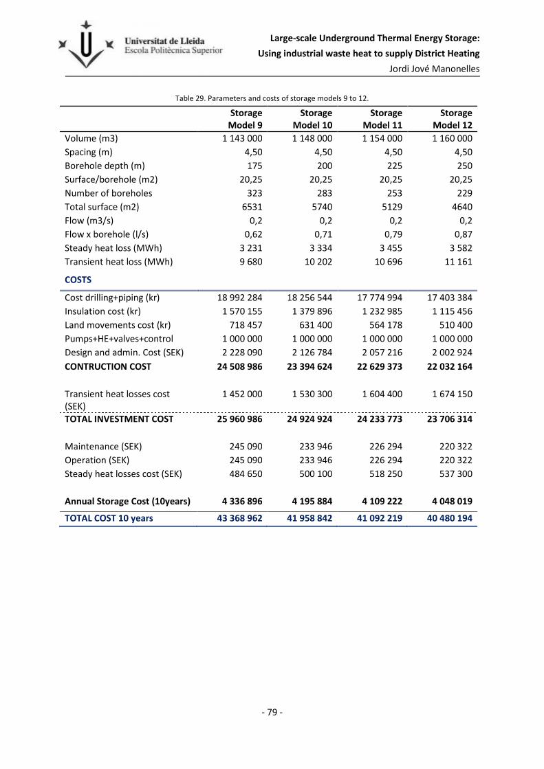
Large-scale Underground Thermal Energy Storage:
Using industrial waste heat to supply District Heating
Jordi Jové Manonelles
- 79 -
Table 29. Parameters and costs of storage models 9 to 12.
Storage
Model 9
Storage
Model 10
Storage
Model 11
Storage
Model 12
Volume (m3) 1 143 000 1 148 000 1 154 000 1 160 000
Spacing (m) 4,50 4,50 4,50 4,50
Borehole depth (m) 175 200 225 250
Surface/borehole (m2) 20,25 20,25 20,25 20,25
Number of boreholes 323 283 253 229
Total surface (m2) 6531 5740 5129 4640
Flow (m3/s) 0,2 0,2 0,2 0,2
Flow x borehole (l/s) 0,62 0,71 0,79 0,87
Steady heat loss (MWh) 3 231 3 334 3 455 3 582
Transient heat loss (MWh) 9 680 10 202 10 696 11 161
COSTS
Cost drilling+piping (kr) 18 992 284 18 256 544 17 774 994 17 403 384
Insulation cost (kr) 1 570 155 1 379 896 1 232 985 1 115 456
Land movements cost (kr) 718 457 631 400 564 178 510 400
Pumps+HE+valves+control 1 000 000 1 000 000 1 000 000 1 000 000
Design and admin. Cost (SEK) 2 228 090 2 126 784 2 057 216 2 002 924
CONTRUCTION COST 24 508 986 23 394 624 22 629 373 22 032 164
Transient heat losses cost (SEK)
1 452 000 1 530 300 1 604 400 1 674 150
TOTAL INVESTMENT COST 25 960 986 24 924 924 24 233 773 23 706 314
Maintenance (SEK) 245 090 233 946 226 294 220 322
Operation (SEK) 245 090 233 946 226 294 220 322
Steady heat losses cost (SEK) 484 650 500 100 518 250 537 300
Annual Storage Cost (10years) 4 336 896 4 195 884 4 109 222 4 048 019
TOTAL COST 10 years 43 368 962 41 958 842 41 092 219 40 480 194

Large-scale Underground Thermal Energy Storage:
Using industrial waste heat to supply District Heating
Jordi Jové Manonelles
- 80 -
Table 30. Parameters and costs of storage models 13 to 16.
Storage
Model 13
Storage
Model 14
Storage
Model 15
Storage
Model 16
Volume (m3) 1 048 000 1 052 000 1 058 000 1 063 000
Spacing (m) 4,25 4,25 4,25 4,25
Borehole depth (m) 175 200 225 250
Surface/borehole (m2) 18,06 18,06 18,06 18,06
Number of boreholes 332 291 260 235
Total surface (m2) 5989 5260 4702 4252
Flow (m3/s) 0,2 0,2 0,2 0,2
Flow x borehole (l/s) 0,60 0,69 0,77 0,85
Steady heat loss (MWh) 3 150 3 253 3 376 3 503
Transient heat loss (MWh) 9 674 10 201 10 702 11 161
COSTS
Cost drilling+piping (kr) 19 275 908 18 539 070 18 075 828 17 703 910
Insulation cost (kr) 1 439 653 1 264 504 1 130 414 1 022 181
Land movements cost (kr) 658 743 578 600 517 244 467 720
Pumps+HE+valves+control 1 000 000 1 000 000 1 000 000 1 000 000
Design and admin. Cost (SEK) 2 237 430 2 138 217 2 072 349 2 019 381
CONTRUCTION COST 24 611 734 23 520 392 22 795 835 22 213 192
Transient heat losses cost (SEK)
1 451 100 1 530 150 1 605 300 1 674 150
TOTAL INVESTMENT COST 26 062 834 25 050 542 24 401 135 23 887 342
Maintenance (SEK) 246 117 235 204 227 958 222 132
Operation (SEK) 246 117 235 204 227 958 222 132
Steady heat losses cost (SEK) 472 500 487 950 506 400 525 450
Annual Storage Cost (10years) 4 339 991 4 202 518 4 122 375 4 063 234
TOTAL COST 10 years 43 399 909 42 025 176 41 223 753 40 632 339

Large-scale Underground Thermal Energy Storage:
Using industrial waste heat to supply District Heating
Jordi Jové Manonelles
- 81 -
Table 31. Parameters and costs of storage models 17 to 20.
Storage
Model 17
Storage
Model 18
Storage
Model 19
Storage
Model 20
Volume (m3) 963 000 967 000 972 000 977 000
Spacing (m) 4,00 4,00 4,00 4,00
Borehole depth (m) 175 200 225 250
Surface/borehole (m2) 16,00 16,00 16,00 16,00
Number of boreholes 344 302 270 244
Total surface (m2) 5503 4835 4320 3908
Flow (m3/s) 0,2 0,2 0,2 0,2
Flow x borehole (l/s) 0,58 0,66 0,74 0,82
Steady heat loss (MWh) 3 080 3 186 3 309 3 438
Transient heat loss (MWh) 9 681 10 214 10 718 11 184
COSTS
Cost drilling+piping (kr) 19 739 310 19 012 267 18 545 467 18 186 401
Insulation cost (kr) 1 322 887 1 162 334 1 038 528 939 483
Land movements cost (kr) 605 314 531 850 475 200 429 880
Pumps+HE+valves+control 1 000 000 1 000 000 1 000 000 1 000 000
Design and admin. Cost (SEK) 2 266 751 2 170 645 2 105 919 2 055 576
CONTRUCTION COST 24 934 262 23 877 096 23 165 114 22 611 341
Transient heat losses cost (SEK)
1 452 150 1 532 100 1 607 700 1 677 600
TOTAL INVESTMENT COST 26 386 412 25 409 196 24 772 814 24 288 941
Maintenance (SEK) 249 343 238 771 231 651 226 113
Operation (SEK) 249 343 238 771 231 651 226 113
Steady heat losses cost (SEK) 462 000 477 900 496 350 515 700
Annual Storage Cost (10years) 4 377 846 4 246 049 4 167 845 4 113 456
TOTAL COST 10 years 43 778 463 42 460 491 41 678 450 41 134 558

Large-scale Underground Thermal Energy Storage:
Using industrial waste heat to supply District Heating
Jordi Jové Manonelles
- 82 -
Table 32. Parameters and costs of storage models 21 to 24.
Storage
Model 21
Storage
Model 22
Storage
Model 23
Storage
Model 24
Volume (m3) 883 000 887 000 892 000 896 000
Spacing (m) 3,75 3,75 3,75 3,75
Borehole depth (m) 175 200 225 250
Surface/borehole (m2) 14,06 14,06 14,06 14,06
Number of boreholes 359 315 282 255
Total surface (m2) 5046 4435 3964 3584
Flow (m3/s) 0,2 0,2 0,2 0,2
Flow x borehole (l/s) 0,56 0,63 0,71 0,78
Steady heat loss (MWh) 3 009 3 116 3 241 3 369
Transient heat loss (MWh) 9 689 10 424 10 750 11 221
COSTS
Cost drilling+piping (kr) 20 325 430 19 606 475 19 153 004 18 785 678
Insulation cost (kr) 1 212 990 1 066 174 953 052 861 594
Land movements cost (kr) 555 029 487 850 436 089 394 240
Pumps+HE+valves+control 1 000 000 1 000 000 1 000 000 1 000 000
Design and admin. Cost (SEK) 2 309 345 2 216 050 2 154 215 2 104 151
CONTRUCTION COST 25 402 794 24 376 549 23 696 360 23 145 663
Transient heat losses cost (SEK)
1 453 350 1 563 600 1 612 500 1 683 150
TOTAL INVESTMENT COST 26 856 144 25 940 149 25 308 860 24 828 813
Maintenance (SEK) 254 028 243 765 236 964 231 457
Operation (SEK) 254 028 243 765 236 964 231 457
Steady heat losses cost (SEK) 451 350 467 400 486 150 505 350
Annual Storage Cost (10years) 4 437 399 4 314 299 4 237 690 4 183 708
TOTAL COST 10 years 44 373 993 43 142 989 42 376 904 41 837 081

Large-scale Underground Thermal Energy Storage:
Using industrial waste heat to supply District Heating
Jordi Jové Manonelles
- 83 -
C. Storage model 8
The main parameters of storage 8 are shown in Table 33:
Table 33. Storage model 8 parameters.
Drilling pattern Quadratic
Borehole installation Closed, Double U-pipe
Borehole diameter 0,115 m
Borehole spacing 4,75 m
Number of boreholes 224 m2
Storage land area 5060 m2
Storage volume 1265000 m3
Insulation thickness 0,4 m
Ins. Thermal conductivity 0,13 W/m,K
Soil layer 10 m
Soil thermal conductivity 1,4 W/m,K
Soil volumetric heat capacity 2,5E6 J/m3K
Bedrock layer 1000 m
Bedrock thermal conductivity 3,45 W/m,K
Bedrock volumetric heat capacity 2,16E6 J/m3K
Borehole pipe diameter 32,6 mm
Borehole pipe thickness 3 mm
Borehole pipe thermal conductivity 0,42 W/m,K
The results obtained with DST are in Table 34, the simulation starts in May and it goes on for ten
years.
Table 34. Storage model 8, results.
t
[days] Tin [
oC]
Tout [
oC]
Tmean
storage [
oC]
Tair [
oC]
Qdem [kW]
Injection [GJ]
Extraction [GJ]
Losses
Top [GJ]
Losses
Side [GJ]
Losses
Bottom [GJ]
30 75 60,2 17,4 10,4 6 300 36 343 0 8 1 282 108 60 70 58,8 26,5 15,9 6 300 63 412 0 23 3 499 280
91 70 60,7 33,7 18 6 300 85 930 0 43 6 078 479
121 75 66,1 40,4 16 6 300 107 366 0 66 8 953 700
152 80 71,4 46,7 10,6 6 300 127 961 0 97 12 103 942
182 33 40,5 44,3 3,1 -1 576 128 219 4 085 134 14 674 1 131
213 23,6 35 40,8 -4,4 -3 068 128 219 11 647 174 16 508 1 265
243 28,3 35 38,4 -9,9 -2 825 128 219 16 522 218 17 991 1 372
273 31,4 35 36,8 -12 -3 783 128 219 19 280 267 19 323 1 469
304 33,4 35 35,8 -10 -3 833 128 219 20 656 319 20 577 1 560
334 34,8 35 35,1 -4,6 -2 738 128 219 21 127 369 21 785 1 647

Large-scale Underground Thermal Energy Storage:
Using industrial waste heat to supply District Heating
Jordi Jové Manonelles
- 84 -
365 34,7 34,7 34,7 2,9 -1 568 128 219 21 143 414 22 958 1 733
395 75 66,4 41,6 10,4 6 300 149 184 21 143 456 24 826 1 879
425 70 63,8 46,1 15,9 6 300 163 936 21 143 497 27 156 2 057
456 70 64,8 49,6 18 6 300 176 443 21 143 536 29 636 2 247
486 75 69,5 53,4 16 6 300 189 709 21 143 574 32 287 2 450
517 80 74,2 57,4 10,6 6 300 203 610 21 143 618 35 130 2 669
547 43,8 51,3 55 3,1 -1 576 203 786 25 227 666 37 545 2 849
578 29,4 44,1 51,3 -4,4 -3 068 203 786 33 236 717 39 353 2 983
608 27,9 41,4 48 -9,9 -2 825 203 786 40 668 773 40 772 3 087
638 17 35 44 -12 -3 783 203 786 50 576 830 41 828 3 162
669 23,6 35 40,7 -10 -3 833 203 786 58 496 888 42 614 3 217
699 27,9 35 38,6 -4,6 -2 738 203 786 63 517 942 43 315 3 267
730 30,7 35 37,2 2,9 -1 568 203 786 66 620 990 43 997 3 315
760 75 67 43,8 10,4 6 300 223 454 66 653 1 034 45 438 3 430
790 70 64,3 48 15,9 6 300 237 038 66 653 1 076 47 385 3 581
821 70 65,2 51,3 18 6 300 248 522 66 653 1 117 49 512 3 745
851 75 69,8 54,9 16 6 300 260 888 66 653 1 157 51 833 3 924
882 80 74,5 58,7 10,6 6 300 273 995 66 653 1 201 54 369 4 121
912 45,2 52,7 56,4 3,1 -1 576 274 160 70 737 1 251 56 513 4 281
943 31 45,6 52,8 -4,4 -3 068 274 160 78 745 1 304 58 089 4 398
973 29,5 43 49,6 -9,9 -2 825 274 160 86 176 1 360 59 302 4 487
1003 18,6 36,7 45,6 -12 -3 783 274 160 96 082 1 420 60 174 4 550
1034 21,1 35 42 -10 -3 833 274 160 105 352 1 478 60 750 4 590
1064 26 35 39,5 -4,6 -2 738 274 160 111 536 1 533 61 210 4 621
1095 29,2 35 37,9 2,9 -1 568 274 160 115 402 1 582 61 655 4 652
1125 75 67,2 44,5 10,4 6 300 293 443 115 446 1 627 62 875 4 751
1155 70 64,5 48,6 15,9 6 300 306 660 115 446 1 670 64 623 4 887
1186 70 65,3 51,9 18 6 300 317 806 115 446 1 710 66 555 5 037
1216 75 70 55,5 16 6 300 329 860 115 446 1 751 68 693 5 203
1247 80 74,7 59,2 10,6 6 300 342 677 115 446 1 796 71 054 5 387
1277 45,7 53,3 57 3,1 -1 576 342 838 119 533 1 846 73 037 5 536
1308 31,6 46,2 53,5 -4,4 -3 068 342 838 127 540 1 899 74 472 5 642
1338 30,1 43,6 50,3 -9,9 -2 825 342 838 134 972 1 956 75 563 5 722
1368 19,4 37,4 46,3 -12 -3 783 342 838 144 880 2 016 76 317 5 776
1399 19,9 35 42,6 -10 -3 833 342 838 154 548 2 075 76 763 5 807
1429 25 35 40 -4,6 -2 738 342 838 161 198 2 131 77 078 5 829
1460 28,3 35 38,4 2,9 -1 568 342 838 165 293 2 179 77 382 5 851
1490 75 67,3 44,9 10,4 6 300 361 882 165 343 2 225 78 480 5 941
1520 70 64,6 49 15,9 6 300 374 872 165 343 2 268 80 103 6 068
1551 70 65,4 52,3 18 6 300 385 809 165 343 2 309 81 915 6 209
1581 75 70,1 55,8 16 6 300 397 670 165 343 2 350 83 930 6 366
1612 80 74,7 59,5 10,6 6 300 410 307 165 343 2 395 86 174 6 542
1642 46,1 53,6 57,3 3,1 -1 576 410 466 169 425 2 445 88 056 6 684
1673 32 46,6 53,8 -4,4 -3 068 410 466 177 438 2 498 89 399 6 783

Large-scale Underground Thermal Energy Storage:
Using industrial waste heat to supply District Heating
Jordi Jové Manonelles
- 85 -
1703 30,5 44 50,7 -9,9 -2 825 410 466 184 876 2 556 90 402 6 857
1733 19,8 37,9 46,8 -12 -3 783 410 466 194 787 2 616 91 073 6 905
1764 19,1 35 43 -10 -3 833 410 466 204 646 2 676 91 439 6 930
1794 24,3 35 40,4 -4,6 -2 738 410 466 211 542 2 731 91 669 6 946
1825 27,6 35,1 38,8 2,9 -1 568 410 466 215 691 2 781 91 897 6 962
1855 75 67,3 45,2 10,4 6 300 429 317 215 748 2 826 92 910 7 046
1885 70 64,7 49,3 15,9 6 300 442 130 215 748 2 870 94 450 7 166
1916 70 65,5 52,5 18 6 300 452 907 215 748 2 911 96 181 7 301
1946 75 70,1 56 16 6 300 464 620 215 748 2 952 98 118 7 453
1977 80 74,8 59,7 10,6 6 300 477 121 215 748 2 997 100 285 7 623
2007 46,3 53,9 57,6 3,1 -1 576 477 278 219 829 3 047 102 092 7 759
2038 32,2 46,9 54,1 -4,4 -3 068 477 278 227 843 3 101 103 368 7 854
2068 30,9 44,4 51 -9,9 -2 825 477 278 235 280 3 159 104 306 7 923
2098 20,1 38,2 47,1 -12 -3 783 477 278 245 191 3 219 104 916 7 967
2129 18,4 35 43,3 -10 -3 833 477 278 255 154 3 279 105 222 7 988
2159 23,7 35 40,7 -4,6 -2 738 477 278 262 199 3 335 105 384 7 999
2190 27,9 35,4 39,1 2,9 -1 568 477 278 266 353 3 384 105 544 8 010
2220 75 67,4 45,5 10,4 6 300 495 964 266 409 3 430 106 496 8 089
2250 70 64,7 49,5 15,9 6 300 508 631 266 409 3 474 107 974 8 205
2281 70 65,6 52,8 18 6 300 519 276 266 409 3 515 109 642 8 336
2311 75 70,2 56,2 16 6 300 530 870 266 409 3 556 111 515 8 483
2342 80 74,8 59,9 10,6 6 300 543 262 266 409 3 602 113 617 8 649
2372 46,5 54,1 57,8 3,1 -1 576 543 418 270 491 3 652 115 370 8 781
2403 32,5 47,1 54,4 -4,4 -3 068 543 418 278 504 3 706 116 594 8 872
2433 31,1 44,6 51,3 -9,9 -2 825 543 418 285 934 3 764 117 481 8 938
2463 20,4 38,5 47,4 -12 -3 783 543 418 295 846 3 825 118 043 8 978
2494 17,9 35 43,6 -10 -3 833 543 418 305 868 3 885 118 304 8 996
2524 23,3 35 40,9 -4,6 -2 738 543 418 313 005 3 941 118 425 9 004
2555 28,1 35,6 39,3 2,9 -1 568 543 418 317 162 3 991 118 541 9 012
2585 75 67,5 45,7 10,4 6 300 561 963 317 219 4 036 119 447 9 088
2615 70 64,8 49,7 15,9 6 300 574 507 317 219 4 080 120 873 9 200
2646 70 65,6 52,9 18 6 300 585 043 317 219 4 122 122 491 9 327
2676 75 70,2 56,4 16 6 300 596 538 317 219 4 163 124 315 9 471
2707 80 74,9 60,1 10,6 6 300 608 840 317 219 4 209 126 371 9 633
2737 46,7 54,2 58 3,1 -1 576 608 994 321 312 4 259 128 078 9 762
2768 32,6 47,3 54,5 -4,4 -3 068 608 994 329 314 4 313 129 259 9 850
2798 31,3 44,8 51,5 -9,9 -2 825 608 994 336 739 4 371 130 104 9 913
2828 20,6 38,7 47,6 -12 -3 783 608 994 346 651 4 432 130 628 9 950
2859 17,4 35 43,8 -10 -3 833 608 994 356 704 4 493 130 853 9 966
2889 22,8 35 41,1 -4,6 -2 738 608 994 363 897 4 549 130 941 9 971
2920 28,4 35,9 39,5 2,9 -1 568 608 994 368 058 4 599 131 024 9 977
2950 75 67,5 45,9 10,4 6 300 627 419 368 115 4 644 131 890 10 050
2980 70 64,8 49,9 15,9 6 300 639 858 368 115 4 689 133 278 10 159
3011 70 65,7 53,1 18 6 300 650 300 368 115 4 730 134 856 10 283

Large-scale Underground Thermal Energy Storage:
Using industrial waste heat to supply District Heating
Jordi Jové Manonelles
- 86 -
3041 75 70,3 56,5 16 6 300 661 712 368 115 4 771 136 641 10 424
3072 80 74,9 60,2 10,6 6 300 673 936 368 115 4 817 138 656 10 583
3102 46,9 54,4 58,1 3,1 -1 576 674 090 372 208 4 867 140 325 10 710
3133 32,8 47,5 54,7 -4,4 -3 068 674 090 380 210 4 921 141 459 10 795
3163 31,5 45 51,6 -9,9 -2 825 674 090 387 635 4 980 142 254 10 856
3193 20,8 38,9 47,8 -12 -3 783 674 090 397 546 5 041 142 738 10 891
3224 16,9 35 44 -10 -3 833 674 090 407 613 5 101 142 923 10 904
3254 22,4 35 41,3 -4,6 -2 738 674 090 414 837 5 158 142 968 10 907
3285 28,6 36,1 39,7 2,9 -1 568 674 090 419 001 5 208 143 002 10 911
3315 75 67,6 46,1 10,4 6 300 692 408 419 058 5 254 143 823 10 981
3345 70 64,9 50,1 15,9 6 300 704 755 419 058 5 298 145 184 11 089
3376 70 65,7 53,2 18 6 300 715 116 419 058 5 339 146 725 11 210
3406 75 70,3 56,7 16 6 300 726 454 419 058 5 381 148 470 11 349
3437 80 74,9 60,3 10,6 6 300 738 612 419 058 5 427 150 450 11 505
3467 47 54,5 58,2 3,1 -1 576 738 764 423 151 5 477 152 087 11 629
3498 32,9 47,6 54,8 -4,4 -3 068 738 764 431 153 5 531 153 187 11 713
3528 31,6 45,1 51,8 -9,9 -2 825 738 764 438 578 5 590 153 954 11 771
3558 21 39 47,9 -12 -3 783 738 764 448 489 5 651 154 411 11 805
3589 16,8 35,1 44,2 -10 -3 833 738 764 458 556 5 712 154 569 11 816
3619 21,9 35 41,5 -4,6 -2 738 738 764 465 791 5 768 154 592 11 818
3650 28,7 36,2 39,9 2,9 -1 568 738 764 469 959 5 818 154 615 11 820
Figure 37. Storage model 8, temperature graph with Inlet T (red line), Outlet T (blue line) and Mean Storage T (green line)

Large-scale Underground Thermal Energy Storage:
Using industrial waste heat to supply District Heating
Jordi Jové Manonelles
- 87 -
D. Storage model 12
The main parameters of storage 12 are shown in Table 35:
Table 35. Storage model 12 parameters
Drilling pattern Quadratic
Borehole installation Closed, Double U-pipe
Borehole diameter 0,115 m
Borehole spacing 4,5 m
Number of boreholes 229 m2
Storage land area 4640 m2
Storage volume 1160000 m3
Insulation thickness 0,4 m
Ins. Thermal conductivity 0,13 W/m,K
Soil layer 10 m
Soil thermal conductivity 1,4 W/m,K
Soil volumetric heat capacity 2,5E6 J/m3K
Bedrock layer 1000 m
Bedrock thermal conductivity 3,45 W/m,K
Bedrock volumetric heat capacity 2,16E6 J/m3K
Borehole pipe diameter 32,6 mm
Borehole pipe thickness 3 mm
Borehole pipe thermal conductivity 0,42 W/m,K
The results obtained with DST are in Table 36 and Figure 38, the simulation starts in May and it goes
on for ten years.
Table 36. Storage model 12, results.
t [days]
Tin [
oC]
Tout [
oC]
Tmean
storage [
oC]
Tair [
oC]
Qdem [kW]
Injection [GJ]
Extraction [GJ]
Losses
Top [GJ]
Losses
Side [GJ]
Losses
Bottom [GJ]
30 75,0 60,2 18,7 10,4 6 300 36 768 0 8 1 360 110
60 70,0 59,0 28,4 15,9 6 300 63 570 0 24 3 692 283
91 70,0 61,0 36,0 18,0 6 300 85 413 0 44 6 382 481
121 75,0 66,5 42,9 16,0 6 300 105 978 0 68 9 353 700
152 80,0 71,9 49,4 10,6 6 300 125 578 0 99 12 587 938
182 35,6 43,1 46,7 3,1 -1 576 125 821 4 085 136 15 233 1 125
213 21,1 35,7 42,7 -4,4 -3 068 125 821 12 094 175 17 114 1 256
243 25,9 35,0 39,4 -9,9 -2 825 125 821 18 657 217 18 551 1 355
273 30,2 35,0 37,4 -12,0 -3 783 125 821 22 401 263 19 804 1 442
304 32,8 35,0 36,1 -10,0 -3 833 125 821 24 283 311 20 978 1 523
334 34,4 35,0 35,3 -4,6 -2 738 125 821 25 008 357 22 112 1 602

Large-scale Underground Thermal Energy Storage:
Using industrial waste heat to supply District Heating
Jordi Jové Manonelles
- 88 -
365 34,8 34,8 34,8 2,9 -1 568 125 821 25 080 399 23 220 1 679
395 75,0 66,4 42,4 10,4 6 300 146 979 25 080 438 25 073 1 819
425 70,0 64,0 47,2 15,9 6 300 161 533 25 080 477 27 416 1 991
456 70,0 65,0 51,0 18,0 6 300 173 638 25 080 513 29 903 2 174
486 75,0 69,7 54,9 16,0 6 300 186 424 25 080 551 32 560 2 370
517 80,0 74,5 59,0 10,6 6 300 199 777 25 080 592 35 419 2 581
547 45,3 52,8 56,4 3,1 -1 576 199 944 29 164 638 37 830 2 753
578 30,8 45,5 52,4 -4,4 -3 068 199 944 37 173 687 39 620 2 880
608 29,0 42,4 48,8 -9,9 -2 825 199 944 44 606 738 41 007 2 977
638 17,8 35,9 44,4 -12,0 -3 783 199 944 54 513 792 42 013 3 046
669 23,1 35,0 40,7 -10,0 -3 833 199 944 62 955 845 42 716 3 093
699 28,0 35,0 38,4 -4,6 -2 738 199 944 68 052 895 43 329 3 135
730 31,0 35,0 36,9 2,9 -1 568 199 944 71 027 938 43 930 3 176
760 75,0 66,9 44,3 10,4 6 300 219 962 71 057 979 45 347 3 285
790 70,0 64,4 48,8 15,9 6 300 233 493 71 057 1 019 47 298 3 430
821 70,0 65,4 52,4 18,0 6 300 244 705 71 057 1 057 49 426 3 587
851 75,0 70,0 56,2 16,0 6 300 256 705 71 057 1 096 51 753 3 760
882 80,0 74,8 60,1 10,6 6 300 269 364 71 057 1 138 54 292 3 949
912 46,5 54,1 57,6 3,1 -1 576 269 522 75 141 1 185 56 430 4 103
943 32,2 46,8 53,7 -4,4 -3 068 269 522 83 149 1 235 57 984 4 213
973 30,4 43,9 50,2 -9,9 -2 825 269 522 90 582 1 288 59 159 4 297
1003 19,3 37,4 45,9 -12,0 -3 783 269 522 100 486 1 343 59 979 4 353
1034 20,7 35,0 41,9 -10,0 -3 833 269 522 109 985 1 397 60 482 4 386
1064 26,2 35,0 39,2 -4,6 -2 738 269 522 116 179 1 447 60 859 4 410
1095 29,7 35,0 37,6 2,9 -1 568 269 522 119 902 1 491 61 234 4 435
1125 75,0 67,1 44,9 10,4 6 300 289 198 119 942 1 533 62 432 4 529
1155 70,0 64,6 49,4 15,9 6 300 302 401 119 942 1 573 64 182 4 660
1186 70,0 65,5 52,9 18,0 6 300 313 310 119 942 1 612 66 123 4 805
1216 75,0 70,2 56,6 16,0 6 300 325 030 119 942 1 650 68 265 4 964
1247 80,0 74,9 60,6 10,6 6 300 337 426 119 942 1 693 70 635 5 142
1277 47,0 54,6 58,1 3,1 -1 576 337 581 124 027 1 740 72 617 5 285
1308 32,7 47,4 54,3 -4,4 -3 068 337 581 132 035 1 790 74 034 5 385
1338 31,0 44,5 50,9 -9,9 -2 825 337 581 139 467 1 844 75 091 5 460
1368 20,0 38,0 46,6 -12,0 -3 783 337 581 149 371 1 899 75 793 5 508
1399 19,5 35,0 42,5 -10,0 -3 833 337 581 159 184 1 954 76 169 5 533
1429 25,2 35,0 39,7 -4,6 -2 738 337 581 165 820 2 004 76 410 5 549
1460 28,8 35,0 38,0 2,9 -1 568 337 581 169 822 2 049 76 642 5 564
1490 75,0 67,2 45,3 10,4 6 300 357 037 169 869 2 091 77 717 5 649
1520 70,0 64,7 49,7 15,9 6 300 370 032 169 869 2 131 79 348 5 772
1551 70,0 65,6 53,2 18,0 6 300 380 750 169 869 2 170 81 165 5 908
1581 75,0 70,2 56,9 16,0 6 300 392 292 169 869 2 209 83 190 6 060
1612 80,0 74,9 60,8 10,6 6 300 404 524 169 869 2 252 85 446 6 230
1642 47,4 54,9 58,4 3,1 -1 576 404 676 173 959 2 299 87 326 6 366
1673 33,1 47,7 54,7 -4,4 -3 068 404 676 181 967 2 349 88 653 6 460

Large-scale Underground Thermal Energy Storage:
Using industrial waste heat to supply District Heating
Jordi Jové Manonelles
- 89 -
1703 31,4 44,9 51,3 -9,9 -2 825 404 676 189 399 2 403 89 622 6 529
1733 20,4 38,5 47,0 -12,0 -3 783 404 676 199 304 2 459 90 243 6 572
1764 18,6 35,0 42,9 -10,0 -3 833 404 676 209 259 2 514 90 542 6 591
1794 24,5 35,0 40,0 -4,6 -2 738 404 676 216 135 2 565 90 693 6 601
1825 28,1 35,0 38,3 2,9 -1 568 404 676 220 254 2 610 90 842 6 611
1855 75,0 67,2 45,5 10,4 6 300 423 958 220 306 2 652 91 834 6 690
1885 70,0 64,7 50,0 15,9 6 300 436 791 220 306 2 693 93 382 6 807
1916 70,0 65,6 53,5 18,0 6 300 447 363 220 306 2 731 95 120 6 938
1946 75,0 70,3 57,2 16,0 6 300 458 771 220 306 2 770 97 068 7 084
1977 80,0 75,0 61,0 10,6 6 300 470 879 220 306 2 813 99 245 7 248
2007 47,6 55,1 58,7 3,1 -1 576 471 029 224 396 2 861 101 056 7 380
2038 33,3 48,0 54,9 -4,4 -3 068 471 029 232 404 2 911 102 316 7 469
2068 31,7 45,2 51,5 -9,9 -2 825 471 029 239 837 2 965 103 221 7 534
2098 20,7 38,8 47,3 -12,0 -3 783 471 029 249 741 3 021 103 783 7 573
2129 17,9 35,0 43,2 -10,0 -3 833 471 029 259 768 3 076 104 025 7 588
2159 24,0 35,0 40,3 -4,6 -2 738 471 029 266 791 3 128 104 122 7 594
2190 27,6 35,1 38,6 2,9 -1 568 471 029 270 941 3 173 104 218 7 600
2220 75,0 67,3 45,8 10,4 6 300 490 157 270 997 3 215 105 149 7 675
2250 70,0 64,8 50,2 15,9 6 300 502 853 270 997 3 256 106 635 7 787
2281 70,0 65,7 53,7 18,0 6 300 513 302 270 997 3 295 108 314 7 914
2311 75,0 70,3 57,3 16,0 6 300 524 599 270 997 3 334 110 198 8 056
2342 80,0 75,0 61,2 10,6 6 300 536 605 270 997 3 377 112 318 8 216
2372 47,8 55,3 58,9 3,1 -1 576 536 754 275 088 3 425 114 072 8 343
2403 33,6 48,2 55,1 -4,4 -3 068 536 754 283 098 3 475 115 281 8 430
2433 31,9 45,4 51,8 -9,9 -2 825 536 754 290 543 3 529 116 137 8 491
2463 21,0 39,0 47,6 -12,0 -3 783 536 754 300 447 3 585 116 652 8 527
2494 17,3 35,0 43,4 -10,0 -3 833 536 754 310 497 3 641 116 853 8 539
2524 23,5 35,0 40,6 -4,6 -2 738 536 754 317 616 3 692 116 903 8 542
2555 27,8 35,3 38,9 2,9 -1 568 536 754 321 769 3 738 116 951 8 545
2585 75,0 67,4 46,0 10,4 6 300 555 744 321 825 3 780 117 835 8 617
2615 70,0 64,8 50,4 15,9 6 300 568 321 321 825 3 821 119 275 8 726
2646 70,0 65,7 53,8 18,0 6 300 578 664 321 825 3 860 120 903 8 849
2676 75,0 70,4 57,5 16,0 6 300 589 867 321 825 3 899 122 741 8 988
2707 80,0 75,1 61,3 10,6 6 300 601 788 321 825 3 942 124 811 9 145
2737 47,9 55,5 59,0 3,1 -1 576 601 937 325 916 3 990 126 521 9 269
2768 33,7 48,4 55,3 -4,4 -3 068 601 937 333 936 4 041 127 690 9 353
2798 32,1 45,6 52,0 -9,9 -2 825 601 937 341 381 4 095 128 505 9 412
2828 21,2 39,3 47,8 -12,0 -3 783 601 937 351 285 4 151 128 984 9 445
2859 16,7 35,0 43,7 -10,0 -3 833 601 937 361 345 4 207 129 149 9 455
2889 23,0 35,0 40,8 -4,6 -2 738 601 937 368 525 4 259 129 163 9 456
2920 28,1 35,5 39,1 2,9 -1 568 601 937 372 682 4 304 129 170 9 457
2950 75,0 67,4 46,2 10,4 6 300 620 806 372 738 4 347 130 017 9 527
2980 70,0 64,9 50,6 15,9 6 300 633 280 372 738 4 388 131 415 9 633
3011 70,0 65,8 54,0 18,0 6 300 643 532 372 738 4 427 133 007 9 753
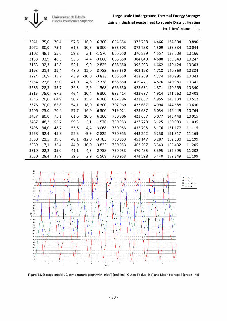
Large-scale Underground Thermal Energy Storage:
Using industrial waste heat to supply District Heating
Jordi Jové Manonelles
- 90 -
3041 75,0 70,4 57,6 16,0 6 300 654 654 372 738 4 466 134 804 9 890
3072 80,0 75,1 61,5 10,6 6 300 666 503 372 738 4 509 136 834 10 044
3102 48,1 55,6 59,2 3,1 -1 576 666 650 376 829 4 557 138 509 10 166
3133 33,9 48,5 55,5 -4,4 -3 068 666 650 384 849 4 608 139 643 10 247
3163 32,3 45,8 52,1 -9,9 -2 825 666 650 392 293 4 662 140 424 10 303
3193 21,4 39,4 48,0 -12,0 -3 783 666 650 402 198 4 718 140 869 10 334
3224 16,9 35,2 43,9 -10,0 -3 833 666 650 412 258 4 774 140 996 10 343
3254 22,6 35,0 41,0 -4,6 -2 738 666 650 419 471 4 826 140 980 10 341
3285 28,3 35,7 39,3 2,9 -1 568 666 650 423 631 4 871 140 959 10 340
3315 75,0 67,5 46,4 10,4 6 300 685 414 423 687 4 914 141 762 10 408
3345 70,0 64,9 50,7 15,9 6 300 697 796 423 687 4 955 143 134 10 512
3376 70,0 65,8 54,1 18,0 6 300 707 969 423 687 4 994 144 688 10 630
3406 75,0 70,4 57,7 16,0 6 300 719 021 423 687 5 034 146 449 10 764
3437 80,0 75,1 61,6 10,6 6 300 730 806 423 687 5 077 148 448 10 915
3467 48,2 55,7 59,3 3,1 -1 576 730 953 427 778 5 125 150 089 11 035
3498 34,0 48,7 55,6 -4,4 -3 068 730 953 435 798 5 176 151 177 11 115
3528 32,4 45,9 52,3 -9,9 -2 825 730 953 443 242 5 230 151 917 11 169
3558 21,5 39,6 48,1 -12,0 -3 783 730 953 453 147 5 287 152 330 11 199
3589 17,1 35,4 44,0 -10,0 -3 833 730 953 463 207 5 343 152 432 11 205
3619 22,2 35,0 41,1 -4,6 -2 738 730 953 470 435 5 395 152 395 11 202
3650 28,4 35,9 39,5 2,9 -1 568 730 953 474 598 5 440 152 349 11 199
Figure 38. Storage model 12, temperature graph with Inlet T (red line), Outlet T (blue line) and Mean Storage T (green line)

Large-scale Underground Thermal Energy Storage:
Using industrial waste heat to supply District Heating
Jordi Jové Manonelles
- 91 -
E. Storage model 16
The main parameters of storage 16 are shown in Table 37:
Table 37. Storage model 16 parameters
Drilling pattern Quadratic
Borehole installation Closed, Double U-pipe
Borehole diameter 0,115 m
Borehole spacing 4,25 m
Number of boreholes 235 m2
Storage land area 4252 m2
Storage volume 1063000 m3
Insulation thickness 0,4 m
Ins. Thermal conductivity 0,13 W/m,K
Soil layer 10 m
Soil thermal conductivity 1,4 W/m,K
Soil volumetric heat capacity 2,5E6 J/m3K
Bedrock layer 1000 m
Bedrock thermal conductivity 3,45 W/m,K
Bedrock volumetric heat capacity 2,16E6 J/m3K
Borehole pipe diameter 32,6 mm
Borehole pipe thickness 3 mm
Borehole pipe thermal conductivity 0,42 W/m,K
The results obtained with DST are in Table 38 and Figure 39, the simulation starts in May and it goes
on for ten years.
Table 38. Storage model 16, results.
t [days]
Tin [
oC]
Tout [
oC]
Tmean
storage [
oC]
Tair [
oC]
Qdem [kW]
Injection [GJ]
Extraction [GJ]
Losses
Top [GJ]
Losses
Side [GJ]
Losses
Bottom [GJ]
30 75,0 60,1 20,3 10,4 6 300 37 437 0 8 1 451 112
60 70,0 59,3 30,7 15,9 6 300 64 003 0 25 3 921 288
91 70,0 61,4 38,6 18,0 6 300 85 129 0 46 6 733 486
121 75,0 67,0 45,7 16,0 6 300 104 777 0 71 9 814 703
152 80,0 72,4 52,2 10,6 6 300 123 344 0 102 13 144 938
182 38,4 45,9 49,3 3,1 -1 576 123 572 4 085 138 15 864 1 122
213 23,7 38,3 44,8 -4,4 -3 068 123 572 12 094 176 17 805 1 252
243 21,9 35,0 40,9 -9,9 -2 825 123 572 19 524 217 19 262 1 348
273 28,3 35,0 38,1 -12,0 -3 783 123 572 24 784 260 20 438 1 425
304 32,0 35,0 36,4 -10,0 -3 833 123 572 27 374 304 21 520 1 497
334 34,1 35,0 35,4 -4,6 -2 738 123 572 28 417 347 22 567 1 567

Large-scale Underground Thermal Energy Storage:
Using industrial waste heat to supply District Heating
Jordi Jové Manonelles
- 92 -
365 34,9 34,9 34,9 2,9 -1 568 123 572 28 585 385 23 602 1 636
395 75,0 66,4 43,4 10,4 6 300 145 065 28 585 422 25 446 1 770
425 70,0 64,1 48,5 15,9 6 300 159 437 28 585 459 27 805 1 937
456 70,0 65,2 52,4 18,0 6 300 171 121 28 585 494 30 308 2 113
486 75,0 70,0 56,5 16,0 6 300 183 412 28 585 530 32 978 2 302
517 80,0 74,7 60,7 10,6 6 300 196 207 28 585 570 35 845 2 506
547 47,0 54,5 57,9 3,1 -1 576 196 366 32 670 613 38 257 2 671
578 32,4 47,0 53,5 -4,4 -3 068 196 366 40 678 659 40 032 2 791
608 30,2 43,7 49,7 -9,9 -2 825 196 366 48 110 708 41 386 2 883
638 18,8 36,8 44,9 -12,0 -3 783 196 366 58 016 758 42 342 2 946
669 22,5 35,0 40,7 -10,0 -3 833 196 366 66 955 806 42 962 2 985
699 28,1 35,0 38,1 -4,6 -2 738 196 366 72 150 852 43 479 3 018
730 31,4 35,0 36,7 2,9 -1 568 196 366 74 969 892 43 999 3 052
760 75,0 66,8 44,9 10,4 6 300 216 888 74 996 930 45 396 3 157
790 70,0 64,5 49,9 15,9 6 300 230 385 74 996 968 47 359 3 297
821 70,0 65,5 53,6 18,0 6 300 241 304 74 996 1 004 49 499 3 449
851 75,0 70,2 57,6 16,0 6 300 252 920 74 996 1 040 51 833 3 615
882 80,0 75,0 61,7 10,6 6 300 265 116 74 996 1 081 54 383 3 798
912 48,1 55,6 58,9 3,1 -1 576 265 267 79 082 1 125 56 519 3 945
943 33,6 48,2 54,7 -4,4 -3 068 265 267 87 094 1 172 58 054 4 050
973 31,4 44,9 50,9 -9,9 -2 825 265 267 94 529 1 222 59 195 4 128
1003 20,1 38,2 46,2 -12,0 -3 783 265 267 104 435 1 273 59 961 4 178
1034 20,1 35,0 41,8 -10,0 -3 833 265 267 114 165 1 322 60 388 4 205
1064 26,4 35,0 38,9 -4,6 -2 738 265 267 120 395 1 368 60 672 4 222
1095 30,2 35,0 37,2 2,9 -1 568 265 267 123 951 1 409 60 963 4 241
1125 75,0 66,9 45,4 10,4 6 300 285 481 123 988 1 447 62 145 4 331
1155 70,0 64,6 50,3 15,9 6 300 298 683 123 988 1 485 63 911 4 458
1186 70,0 65,7 54,1 18,0 6 300 309 327 123 988 1 522 65 864 4 597
1216 75,0 70,4 58,0 16,0 6 300 320 687 123 988 1 558 68 021 4 752
1247 80,0 75,1 62,1 10,6 6 300 332 644 123 988 1 599 70 404 4 923
1277 48,5 56,1 59,4 3,1 -1 576 332 791 128 074 1 644 72 385 5 060
1308 34,1 48,7 55,2 -4,4 -3 068 332 791 136 086 1 691 73 788 5 156
1338 32,0 45,5 51,5 -9,9 -2 825 332 791 143 521 1 741 74 810 5 226
1368 20,8 38,8 46,9 -12,0 -3 783 332 791 153 433 1 792 75 461 5 268
1399 18,8 35,0 42,4 -10,0 -3 833 332 791 163 383 1 843 75 768 5 288
1429 25,4 35,0 39,4 -4,6 -2 738 332 791 170 042 1 889 75 918 5 297
1460 29,3 35,0 37,6 2,9 -1 568 332 791 173 923 1 930 76 072 5 307
1490 75,0 67,0 45,8 10,4 6 300 352 800 173 965 1 968 77 134 5 389
1520 70,0 64,7 50,6 15,9 6 300 365 808 173 965 2 007 78 780 5 508
1551 70,0 65,7 54,3 18,0 6 300 376 274 173 965 2 043 80 613 5 640
1581 75,0 70,4 58,2 16,0 6 300 387 470 173 965 2 080 82 654 5 787
1612 80,0 75,2 62,3 10,6 6 300 399 273 173 965 2 121 84 925 5 951
1642 48,8 56,3 59,7 3,1 -1 576 399 419 178 052 2 166 86 810 6 082
1673 34,4 49,1 55,6 -4,4 -3 068 399 419 186 064 2 213 88 122 6 172

Large-scale Underground Thermal Energy Storage:
Using industrial waste heat to supply District Heating
Jordi Jové Manonelles
- 93 -
1703 32,4 45,9 51,9 -9,9 -2 825 399 419 193 499 2 263 89 061 6 236
1733 21,2 39,2 47,3 -12,0 -3 783 399 419 203 411 2 315 89 632 6 273
1764 17,8 35,0 42,8 -10,0 -3 833 399 419 213 447 2 366 89 865 6 288
1794 24,7 35,0 39,7 -4,6 -2 738 399 419 220 342 2 412 89 939 6 292
1825 28,7 35,0 37,9 2,9 -1 568 399 419 224 389 2 453 90 009 6 297
1855 75,0 67,1 46,0 10,4 6 300 419 262 224 437 2 492 90 986 6 373
1885 70,0 64,8 50,9 15,9 6 300 432 118 224 437 2 530 92 552 6 486
1916 70,0 65,8 54,6 18,0 6 300 442 448 224 437 2 567 94 307 6 613
1946 75,0 70,5 58,4 16,0 6 300 453 519 224 437 2 604 96 271 6 755
1977 80,0 75,2 62,5 10,6 6 300 465 207 224 437 2 645 98 466 6 914
2007 49,0 56,6 59,9 3,1 -1 576 465 351 228 523 2 690 100 282 7 040
2038 34,6 49,3 55,8 -4,4 -3 068 465 351 236 535 2 738 101 530 7 126
2068 32,7 46,2 52,1 -9,9 -2 825 465 351 243 970 2 788 102 406 7 186
2098 21,5 39,5 47,6 -12,0 -3 783 465 351 253 882 2 840 102 920 7 220
2129 17,0 35,0 43,1 -10,0 -3 833 465 351 263 948 2 891 103 099 7 231
2159 24,0 35,0 40,0 -4,6 -2 738 465 351 270 988 2 938 103 118 7 231
2190 28,1 35,0 38,1 2,9 -1 568 465 351 275 115 2 979 103 132 7 232
2220 75,0 67,2 46,3 10,4 6 300 485 050 275 167 3 018 104 049 7 304
2250 70,0 64,8 51,1 15,9 6 300 497 777 275 167 3 056 105 554 7 414
2281 70,0 65,8 54,7 18,0 6 300 507 992 275 167 3 093 107 250 7 536
2311 75,0 70,5 58,6 16,0 6 300 518 960 275 167 3 130 109 153 7 675
2342 80,0 75,3 62,6 10,6 6 300 530 555 275 167 3 171 111 291 7 830
2372 49,2 56,7 60,1 3,1 -1 576 530 697 279 254 3 216 113 054 7 953
2403 34,8 49,5 56,0 -4,4 -3 068 530 697 287 266 3 264 114 251 8 035
2433 32,9 46,4 52,4 -9,9 -2 825 530 697 294 700 3 314 115 079 8 092
2463 21,7 39,8 47,8 -12,0 -3 783 530 697 304 600 3 366 115 549 8 123
2494 16,9 35,2 43,3 -10,0 -3 833 530 697 314 680 3 417 115 685 8 131
2524 23,5 35,0 40,2 -4,6 -2 738 530 697 321 821 3 464 115 657 8 129
2555 27,6 35,1 38,4 2,9 -1 568 530 697 325 982 3 506 115 625 8 127
2585 75,0 67,2 46,5 10,4 6 300 550 263 326 038 3 545 116 496 8 196
2615 70,0 64,9 51,3 15,9 6 300 562 874 326 038 3 583 117 954 8 303
2646 70,0 65,9 54,9 18,0 6 300 572 988 326 038 3 620 119 602 8 423
2676 75,0 70,6 58,7 16,0 6 300 583 865 326 038 3 657 121 457 8 558
2707 80,0 75,3 62,8 10,6 6 300 595 380 326 038 3 699 123 547 8 709
2737 49,4 56,9 60,2 3,1 -1 576 595 521 330 113 3 744 125 267 8 830
2768 35,0 49,7 56,2 -4,4 -3 068 595 521 338 125 3 791 126 424 8 909
2798 33,1 46,6 52,6 -9,9 -2 825 595 521 345 559 3 842 127 212 8 964
2828 21,9 40,0 48,0 -12,0 -3 783 595 521 355 459 3 894 127 647 8 993
2859 17,1 35,4 43,5 -10,0 -3 833 595 521 365 539 3 945 127 748 8 999
2889 23,0 35,0 40,4 -4,6 -2 738 595 521 372 735 3 993 127 686 8 995
2920 27,8 35,3 38,6 2,9 -1 568 595 521 376 900 4 034 127 620 8 991
2950 75,0 67,3 46,7 10,4 6 300 614 965 376 956 4 073 128 455 9 058
2980 70,0 64,9 51,4 15,9 6 300 627 472 376 956 4 112 129 873 9 162
3011 70,0 65,9 55,0 18,0 6 300 637 498 376 956 4 149 131 482 9 279

Large-scale Underground Thermal Energy Storage:
Using industrial waste heat to supply District Heating
Jordi Jové Manonelles
- 94 -
3041 75,0 70,6 58,9 16,0 6 300 648 298 376 956 4 186 133 299 9 411
3072 80,0 75,3 62,9 10,6 6 300 659 743 376 956 4 228 135 351 9 561
3102 49,5 57,0 60,4 3,1 -1 576 659 884 381 031 4 273 137 035 9 679
3133 35,2 49,8 56,3 -4,4 -3 068 659 884 389 042 4 321 138 158 9 756
3163 33,2 46,7 52,7 -9,9 -2 825 659 884 396 477 4 371 138 914 9 809
3193 22,1 40,1 48,2 -12,0 -3 783 659 884 406 377 4 424 139 319 9 836
3224 17,3 35,6 43,7 -10,0 -3 833 659 884 416 457 4 475 139 391 9 840
3254 22,6 35,0 40,6 -4,6 -2 738 659 884 423 685 4 522 139 304 9 834
3285 28,0 35,5 38,8 2,9 -1 568 659 884 427 853 4 564 139 207 9 828
3315 75,0 67,3 46,8 10,4 6 300 679 222 427 909 4 603 140 012 9 893
3345 70,0 65,0 51,6 15,9 6 300 691 640 427 909 4 642 141 398 9 994
3376 70,0 65,9 55,1 18,0 6 300 701 589 427 909 4 679 142 971 10 109
3406 75,0 70,6 59,0 16,0 6 300 712 322 427 909 4 716 144 754 10 240
3437 80,0 75,4 63,0 10,6 6 300 723 706 427 909 4 758 146 773 10 387
3467 49,6 57,1 60,5 3,1 -1 576 723 846 431 984 4 803 148 425 10 503
3498 35,3 49,9 56,4 -4,4 -3 068 723 846 439 995 4 850 149 503 10 579
3528 33,4 46,8 52,8 -9,9 -2 825 723 846 447 430 4 901 150 220 10 630
3558 22,2 40,3 48,3 -12,0 -3 783 723 846 457 330 4 954 150 588 10 655
3589 17,4 35,7 43,9 -10,0 -3 833 723 846 467 410 5 005 150 631 10 658
3619 22,2 35,0 40,8 -4,6 -2 738 723 846 474 653 5 053 150 515 10 650
3650 28,2 35,7 39,0 2,9 -1 568 723 846 478 823 5 094 150 401 10 643
Figure 39. Storage model 16, temperature graph with Inlet T (red line), Outlet T (blue line) and Mean Storage T (green line)

Large-scale Underground Thermal Energy Storage:
Using industrial waste heat to supply District Heating
Jordi Jové Manonelles
- 95 -
S = T� = 4 ∙ T
U ∙ V
WX = S ∙ U�
ℎ� = H ∙ S2 ∙ ! = H ∙ T
2 ∙ ! ∙ �
ℎ= = Z ∙ N ∙ S2 ∙ U ∙ !
F. Pressure drop as a function of flow rate
In order to find the optimum injection flow rate the pressure drop is calculated, because higher
pressure drop means a bigger pump is necessary.
The pipe installation wherein the boreholes are connected in parallel and there is no high difference
between the pumping point and the end point reduces the system total pressure drop.
Calculate the pressure drop consists in a few steps with different equations because the installation
has different pipes: borehole pipe, connection between boreholes, manifold and culvert. Each pipe
has different diameter and the only one condition is the flow must be turbulent because of better
heat transfer.
The length of each pipe is calculated depending on the storage model parameters, mainly the
borehole spacing and depth. Except the culvert length, it is assumed to be twice one storage side
plus 50 meters, these 50 meters is the estimation for the machinery house location.
Hence, the calculation is the following:
( A 1)
( A 2)
With equation ( A 1) the velocity is calculated by the flow rate Q, in the case of the borehole pipe the
total flow rate is divided for the number of boreholes. Then equation ( A 2) is used to confirm the
flow is turbulent, when Reynolds number is over 4000.
The losses are divided in two: the major losses caused by friction along the pipe length and the minor
losses caused by pipe components. The total pressure drop ℎ is the sum of the major ℎ= and minor
losses ℎ�, see equation( A 3).
ℎ = ℎ= + ℎ�
( A 3)
( A 4)
( A 5)
The minor loses depend on the coefficient H for each component (see
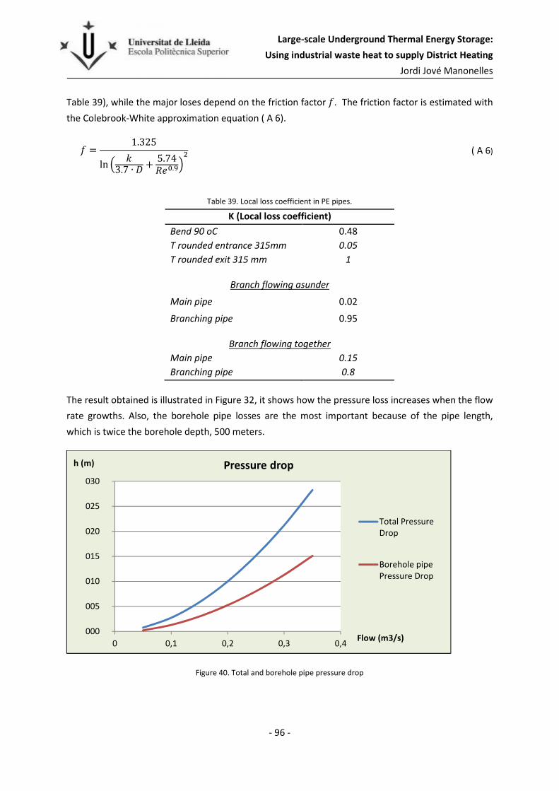
Large-scale Underground Thermal Energy Storage:
Using industrial waste heat to supply District Heating
Jordi Jové Manonelles
- 96 -
Table 39), while the major loses depend on the friction factor Z. The friction factor is estimated with
the Colebrook-White approximation equation ( A 6).
Z = 1.325ln ] ^
3.7 ∙ U +5.74WX`.ab
( A 6)
Table 39. Local loss coefficient in PE pipes.
K (Local loss coefficient)
Bend 90 oC 0.48
T rounded entrance 315mm 0.05
T rounded exit 315 mm 1
Branch flowing asunder
Main pipe 0.02
Branching pipe 0.95
Branch flowing together
Main pipe 0.15
Branching pipe 0.8
The result obtained is illustrated in Figure 32, it shows how the pressure loss increases when the flow
rate growths. Also, the borehole pipe losses are the most important because of the pipe length,
which is twice the borehole depth, 500 meters.
Figure 40. Total and borehole pipe pressure drop
000
005
010
015
020
025
030
0 0,1 0,2 0,3 0,4
h (m)
Flow (m3/s)
Pressure drop
Total PressureDrop
Borehole pipePressure Drop

Large-scale Underground Thermal Energy Storage:
Using industrial waste heat to supply District Heating
Jordi Jové Manonelles
- 97 -
A summary of the results is shown below in Table 40. These results and the chart above correspond
to the calculations made for the optimum model, storage model the number 12 with 229 boreholes,
4.5 m of borehole spacing and 250 m depth , more data in page- 87 -.
Table 40. Pressure drop calculations for the optimum storage (model 12) with injection flow of 0.2m/s.
Borehole pipe Section pipe Collector pipe
Diameter (m) 3.26E-02 9.68E-02 3.15E-01
Flow (m3/s) 4.37E-04 1.33E-02 2.00E-01
Area (m2) 8.35E-04 7.36E-03 7.79E-02
Velocity (m/s) 0.52 1.81 2.57
Re 2.59E+04 2.67E+05 1.23E+06
f 2.43E-02 1.49E-02 1.13E-02
hmajorloss (m) 5.21 1.76 2.27
hminorloss (m) 0.04 0.32 0.41
Total h 10.01