Embed Size (px)
Citation preview
BCool# 1
Large Series BAWC/H - L
b cool manufacturers of air-conditioning equipment ltd
Ver. 3.02 01_18
PACKAGED AIR TO WATER CHILLERS / HEAT PUMPSCOOLING / HEATING APPLICATIONS
OUTDOOR INSTALLATION
2 #BCool
bAwc/H - L R410a
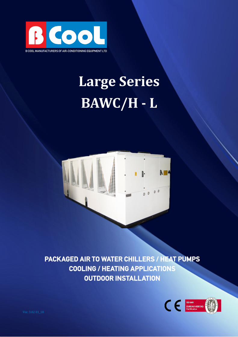
The BCOOL BAWC/H large ca-pacity series includes packaged air cooled water chillers and heat pumps for cooling and heating applications and outdoor installation. They are available in several types and mod-els, with nominal capacities ranging from 217,1 to 679,1 kW in cooling and 241,5 to 757,7 kW in heating.
The BCOOL BAWC/H - L series is ideal, in combination with water terminal units or air-handling units, for air-conditioning of office-buildings, business centers, shopping centers, hotels, hospitals, banks, entertainment centers, etc., or for supplying cold or hot water in industrial applications.
En
gin
eeri
ng
Dat
a
HeAting CApACity241,5 kW - 757,7 kW (R410a)
COOLing CApACity217,1 kW - 679,1 kW (R410a)
Optimized design for R410a refrigerant
➜Casing: Galvanized Steel plate with polyesteric coating ➜Assembly: Fully bolted/welding free ➜Compressor: Hermetically sealed scroll type ➜Air heat exchanger: Cross finned coil, internally grooved copper tubes and louvered aluminium fins ➜Direct drive propeller fan: Low rpm, quiet operation ➜Water heat exchanger: Shell and tube type ➜Hydromodule ➜Safety and functional devices: ➜High/low pressure switch ➜Phase sequence - phase failure - reverse phase and voltage monitoring device ➜Evaporator low temperature protection ➜Electronic microprocessor control with digital display ➜Differential water pressure switch ➜High and low pressure manometers ➜Step function fan control or linear fan speed regulation control, according to coil temperatures ➜Various optional capabilities
BCool# 3
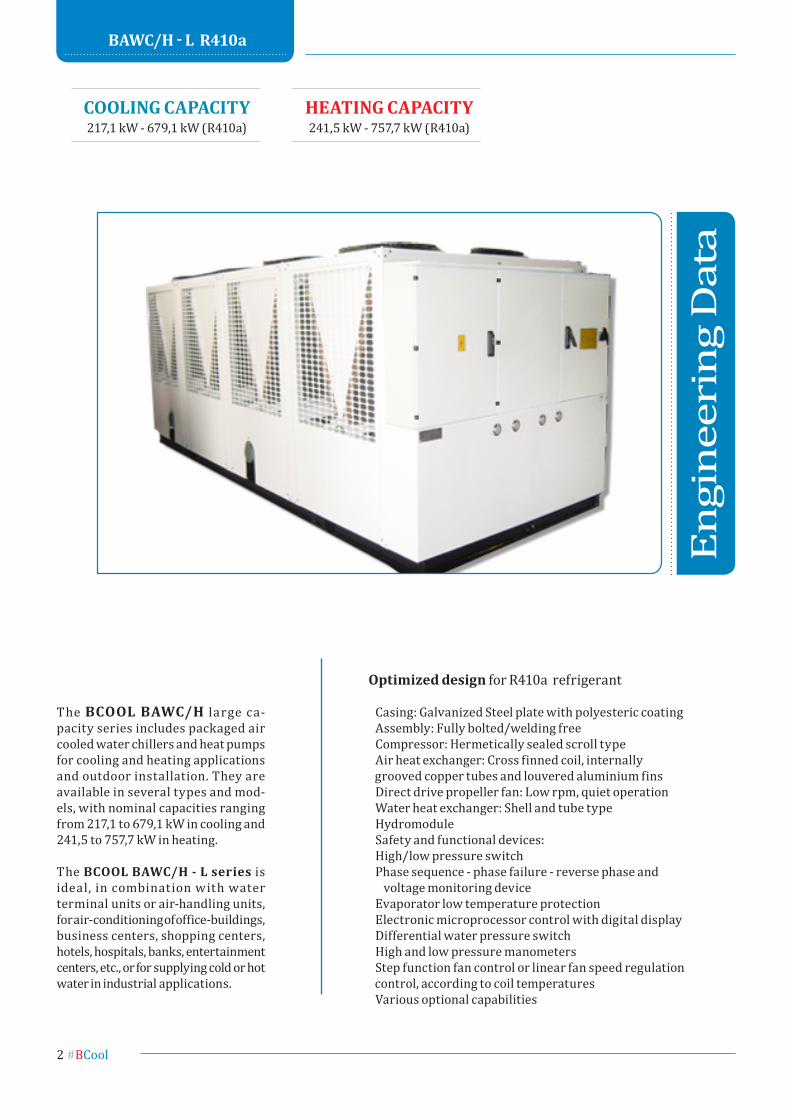
nomenclature
1 2 3 4 5 6 7
1 BCOOL
2 Air Cooled Water Chiller or Heat Pump
3 C-Cooling only, H-Heat Pump
4 capacity (RT)
5 Series
L-large
6 Optional
HD-Hydronic
pK-Pump Kit
7 Refrigerant Liquid
R410a
nomenclatureB - A W - X - X X X - X - X - X
4 #BCool
Contents
1.0 TecHnicAL DescRipTion
2.0 bAwc/H - L R410a 2.1 Specifications BAWC/H - L R410a 2.2 Cooling capacity table R410a 2.3 Heating capacity table R410a 2.4 Operational range R410a 2.5 Sound data
3.0 ouTLook DRAwings
4.0 HyDRAuLic ciRcuiTs 4.1 Water pressure drop curves 4.2 About hydraulic circuits 4.2.1 Recommendations concerning the hydraulic circuit 4.2.2 Water charge, flow and quality 4.3 Recommended hydraulic circuit diagram
5.0 RefRigeRAnT ciRcuiT 5.1 BAWC - L 5.2 BAWH - L 5.3 Operating pressure of the refrigerant circuit
6.0 wiRing DiAgRAm
7.0 guiDe specificATions
BCool# 5
1.0 Technical Description
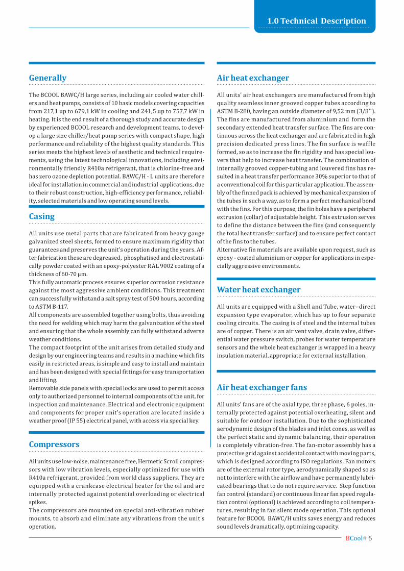
generally
The BCOOL BAWC/H large series, including air cooled water chill-ers and heat pumps, consists of 10 basic models covering capacities from 217,1 up to 679,1 kW in cooling and 241,5 up to 757,7 kW in heating. It is the end result of a thorough study and accurate design by experienced BCOOL research and development teams, to devel-op a large size chiller/heat pump series with compact shape, high performance and reliability of the highest quality standards. This series meets the highest levels of aesthetic and technical require-ments, using the latest technological innovations, including envi-ronmentally friendly R410a refrigerant, that is chlorine-free and has zero ozone depletion potential. BAWC/H - L units are therefore ideal for installation in commercial and industrial applications, due to their robust construction, high-efficiency performance, reliabil-ity, selected materials and low operating sound levels.
Casing
All units use metal parts that are fabricated from heavy gauge galvanized steel sheets, formed to ensure maximum rigidity that guarantees and preserves the unit's operation during the years. Af-ter fabrication these are degreased, phosphatised and electrostati-cally powder coated with an epoxy-polyester RAL 9002 coating of a thickness of 60-70 μm.This fully automatic process ensures superior corrosion resistance against the most aggressive ambient conditions. This treatment can successfully withstand a salt spray test of 500 hours, according to ASTM B-117.All components are assembled together using bolts, thus avoiding the need for welding which may harm the galvanization of the steel and ensuring that the whole assembly can fully withstand adverse weather conditions.The compact footprint of the unit arises from detailed study and design by our engineering teams and results in a machine which fits easily in restricted areas, is simple and easy to install and maintain and has been designed with special fittings for easy transportation and lifting.Removable side panels with special locks are used to permit access only to authorized personnel to internal components of the unit, for inspection and maintenance. Electrical and electronic equipment and components for proper unit's operation are located inside a weather proof (IP 55) electrical panel, with access via special key.
Compressors
All units use low-noise, maintenance free, Hermetic Scroll compres-sors with low vibration levels, especially optimized for use with R410a refrigerant, provided from world class suppliers. They are equipped with a crankcase electrical heater for the oil and are internally protected against potential overloading or electrical spikes.The compressors are mounted on special anti-vibration rubber mounts, to absorb and eliminate any vibrations from the unit's operation.
Air heat exchanger
All units' air heat exchangers are manufactured from high quality seamless inner grooved copper tubes according to ASTM B-280, having an outside diameter of 9,52 mm (3/8'').The fins are manufactured from aluminium and form the secondary extended heat transfer surface. The fins are con-tinuous across the heat exchanger and are fabricated in high precision dedicated press lines. The fin surface is waff le formed, so as to increase the fin rigidity and has special lou-vers that help to increase heat transfer. The combination of internally grooved copper-tubing and louvered fins has re-sulted in a heat transfer performance 30% superior to that of a conventional coil for this particular application. The assem-bly of the finned pack is achieved by mechanical expansion of the tubes in such a way, as to form a perfect mechanical bond with the fins. For this purpose, the fin holes have a peripheral extrusion (collar) of adjustable height. This extrusion serves to define the distance between the fins (and consequently the total heat transfer surface) and to ensure perfect contact of the fins to the tubes. Alternative fin materials are available upon request, such as epoxy - coated aluminium or copper for applications in espe-cially aggressive environments.
water heat exchanger
All units are equipped with a Shell and Tube, water–direct expansion type evaporator, which has up to four separate cooling circuits. The casing is of steel and the internal tubes are of copper. There is an air vent valve, drain valve, differ-ential water pressure switch, probes for water temperature sensors and the whole heat exchanger is wrapped in a heavy insulation material, appropriate for external installation.
Air heat exchanger fans
All units' fans are of the axial type, three phase, 6 poles, in-ternally protected against potential overheating, silent and suitable for outdoor installation. Due to the sophisticated aerodynamic design of the blades and inlet cones, as well as the perfect static and dynamic balancing, their operation is completely vibration-free. The fan-motor assembly has a protective grid against accidental contact with moving parts, which is designed according to ISO regulations. Fan motors are of the external rotor type, aerodynamically shaped so as not to interfere with the airflow and have permanently lubri-cated bearings that to do not require service. Step function fan control (standard) or continuous linear fan speed regula-tion control (optional) is achieved according to coil tempera-tures, resulting in fan silent mode operation. This optional feature for BCOOL BAWC/H units saves energy and reduces sound levels dramatically, optimizing capacity.
6 #BCool
1.0 Technical Description
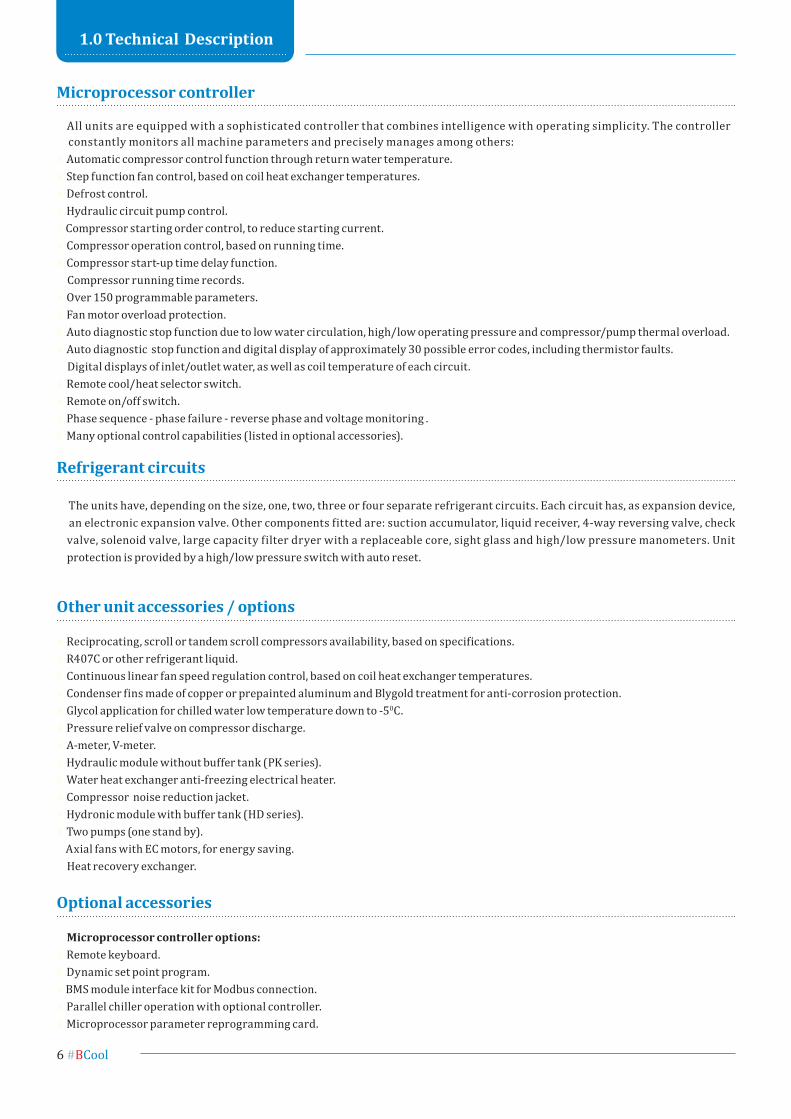
microprocessor controller
All units are equipped with a sophisticated controller that combines intelligence with operating simplicity. The controller constantly monitors all machine parameters and precisely manages among others:Automatic compressor control function through return water temperature.Step function fan control, based on coil heat exchanger temperatures.Defrost control.Hydraulic circuit pump control. Compressor starting order control, to reduce starting current.Compressor operation control, based on running time.Compressor start-up time delay function. Compressor running time records.Over 150 programmable parameters.Fan motor overload protection.Auto diagnostic stop function due to low water circulation, high/low operating pressure and compressor/pump thermal overload.Auto diagnostic stop function and digital display of approximately 30 possible error codes, including thermistor faults. Digital displays of inlet/outlet water, as well as coil temperature of each circuit.Remote cool/heat selector switch.Remote on/off switch.Phase sequence - phase failure - reverse phase and voltage monitoring .Many optional control capabilities (listed in optional accessories).
Optional accessories
microprocessor controller options:Remote keyboard.Dynamic set point program. BMS module interface kit for Modbus connection. Parallel chiller operation with optional controller.Microprocessor parameter reprogramming card.
other unit accessories / options
Reciprocating, scroll or tandem scroll compressors availability, based on specifications.R407C or other refrigerant liquid.Continuous linear fan speed regulation control, based on coil heat exchanger temperatures.Condenser fins made of copper or prepainted aluminum and Blygold treatment for anti-corrosion protection.Glycol application for chilled water low temperature down to -50C. Pressure relief valve on compressor discharge.A-meter, V-meter.Hydraulic module without buffer tank (PK series).Water heat exchanger anti-freezing electrical heater.Compressor noise reduction jacket.Hydronic module with buffer tank (HD series).Two pumps (one stand by). Axial fans with EC motors, for energy saving. Heat recovery exchanger.
Refrigerant circuits
The units have, depending on the size, one, two, three or four separate refrigerant circuits. Each circuit has, as expansion device, an electronic expansion valve. Other components fitted are: suction accumulator, liquid receiver, 4-way reversing valve, check valve, solenoid valve, large capacity filter dryer with a replaceable core, sight glass and high/low pressure manometers. Unit protection is provided by a high/low pressure switch with auto reset.
BCool# 7
BAW
C/H
- L
R41
0a
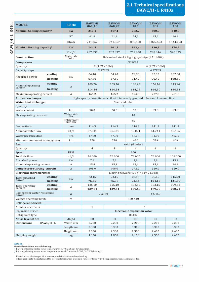
2.1 Technical specifications bAwc/H - L R410a
moDeL 50 Hz BAWC/H 060_1c
BAWC/H 060_2c
BAWC/H 075
BAWC/H 085
BAWC/H 100
nominal Cooling capacity1 kW 217,1 217,1 262,2 300,9 340,0
RT 61,8 61,8 74,6 85,6 96,8
Btu/h 741.367 741.367 895.528 1.027.593 1.161.093
nominal Heating capacity2 kW 241,5 241,5 293,6 336,2 378,8
Kcal/h 207.837 207.837 252.658 289.346 326.033
Construction Material/Color Galvanized steel / Light grey-beige (RAL 9002)
Compressor SCROLLQuantity 2 (1 TANDEM) 4 (2 TANDEM)Capacity steps 2 STEPS 4 STEPS
Absorbed powercooling
kW64,40 64,40 79,80 90,90 102,00
heating 67,60 67,60 84,40 96,40 108,40
Nominal operatingcurrent
coolingA
109,70 109,70 138,28 156,76 175,24
heating 114,24 114,24 144,28 164,30 184,32
Maximum operating current A 165,2 165,2 194,0 227,8 261,6Air heat exchanger High capacity cross finned coil with internally grooved tubes and louvered finswater heat exchanger Shell and tubeQuantity 1Water content Lit. 50,0 50,0 55,0 93,0 93,0
Max. operating pressure Water side Bar 10
Refrigerant side Bar 45
Connections mm 114,3 114,3 114,3 141,3 141,3
Nominal water flow Lit/h 37.331 37.331 45.094 51.744 58.466
Water pressure drop kPa 47,00 47,00 53,00 31,00 40,00
Minimum content of water system Lit. 778 778 470 539 609fan Axial (6 poles)Quantity 4 4 4 4 4Speed RPM 900Total air flow m3/h 76.000 76.000 76.000 76.000 108.000Absorbed power kW 7,8 7,8 7,8 7,8 13,2Nominal operating current A 15,4 15,4 15,4 15,4 24,4Compressor starting current A 408,0 408,0 272,0 310,0 310,0electrical characteristics Electric network 400 V / 3 Ph / 50 Hz
Total absorbedpower
coolingkW
72,16 72,16 87,56 98,66 115,20heating 75,36 75,36 92,16 104,16 121,60
Total operating current
coolingA
125,10 125,10 153,68 172,16 199,64heating 129,64 129,64 159,68 179,70 208,72
Compressor carter resistance power W 2 X150 4 X 150
Voltage operating limits V 360-440Refrigerant circuitNumber of circuits 1 2Expansion device electronic expansion valveRefrigerant type R410anoise level @ 5m db(A) 80 80 80 80 82Dimensions BAWC/H - L Width mm 2.200 2.200 2.200 2.200 2.200
Length mm 3.300 3.300 3.300 3.300 3.300Height mm 2.380 2.380 2.380 2.400 2.400
Shipping weight kg 1.850 1.850 2.150 2.350 2.450
NOTESnominal conditions are as following:1 Entering / leaving chilled water temperature 12 / 7oC, ambient 35oC (cooling).2 Entering / leaving heated water temperature 40 / 45oC, ambient 7oC DB / 6oC WB (heating).
Electrical installation specifications are purely indicative and non-binding. All connections to the system and the electrical installation must be in full accordance with the applicable national and local codes.
8 #BCool
BAW
C/H
- L
R41
0a
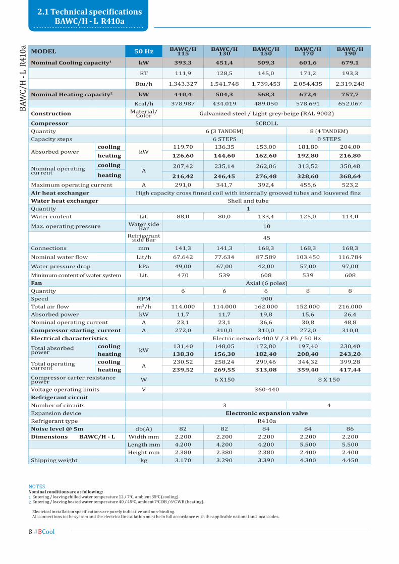
moDeL 50 Hz BAWC/H 115
BAWC/H 130
BAWC/H 150
BAWC/H 170
BAWC/H 190
nominal Cooling capacity1 kW 393,3 451,4 509,3 601,6 679,1
RT 111,9 128,5 145,0 171,2 193,3
Btu/h 1.343.327 1.541.748 1.739.453 2.054.435 2.319.248
nominal Heating capacity2 kW 440,4 504,3 568,3 672,4 757,7
Kcal/h 378.987 434.019 489.050 578.691 652.067
Construction Material/Color Galvanized steel / Light grey-beige (RAL 9002)
Compressor SCROLLQuantity 6 (3 TANDEM) 8 (4 TANDEM)Capacity steps 6 STEPS 8 STEPS
Absorbed powercooling
kW119,70 136,35 153,00 181,80 204,00
heating 126,60 144,60 162,60 192,80 216,80
Nominal operatingcurrent
coolingA
207,42 235,14 262,86 313,52 350,48
heating 216,42 246,45 276,48 328,60 368,64Maximum operating current A 291,0 341,7 392,4 455,6 523,2Air heat exchanger High capacity cross finned coil with internally grooved tubes and louvered finswater heat exchanger Shell and tubeQuantity 1Water content Lit. 88,0 80,0 133,4 125,0 114,0
Max. operating pressure Water side Bar 10
Refrigerant side Bar 45
Connections mm 141,3 141,3 168,3 168,3 168,3Nominal water flow Lit/h 67.642 77.634 87.589 103.450 116.784
Water pressure drop kPa 49,00 67,00 42,00 57,00 97,00Minimum content of water system Lit. 470 539 608 539 608fan Axial (6 poles)Quantity 6 6 6 8 8Speed RPM 900Total air flow m3/h 114.000 114.000 162.000 152.000 216.000Absorbed power kW 11,7 11,7 19,8 15,6 26,4Nominal operating current A 23,1 23,1 36,6 30,8 48,8Compressor starting current A 272,0 310,0 310,0 272,0 310,0electrical characteristics Electric network 400 V / 3 Ph / 50 Hz
Total absorbed power
coolingkW
131,40 148,05 172,80 197,40 230,40heating 138,30 156,30 182,40 208,40 243,20
Total operating current
coolingA
230,52 258,24 299,46 344,32 399,28heating 239,52 269,55 313,08 359,40 417,44
Compressor carter resistance power W 6 X150 8 X 150
Voltage operating limits V 360-440Refrigerant circuitNumber of circuits 3 4Expansion device electronic expansion valveRefrigerant type R410anoise level @ 5m db(A) 82 82 84 84 86Dimensions BAWC/H - L Width mm 2.200 2.200 2.200 2.200 2.200
Length mm 4.200 4.200 4.200 5.500 5.500Height mm 2.380 2.380 2.380 2.400 2.400
Shipping weight kg 3.170 3.290 3.390 4.300 4.450
2.1 Technical specifications bAwc/H - L R410a
NOTESnominal conditions are as following:1 Entering / leaving chilled water temperature 12 / 7oC, ambient 35oC (cooling).2 Entering / leaving heated water temperature 40 / 45oC, ambient 7oC DB / 6oC WB (heating).
Electrical installation specifications are purely indicative and non-binding. All connections to the system and the electrical installation must be in full accordance with the applicable national and local codes.
BCool# 9
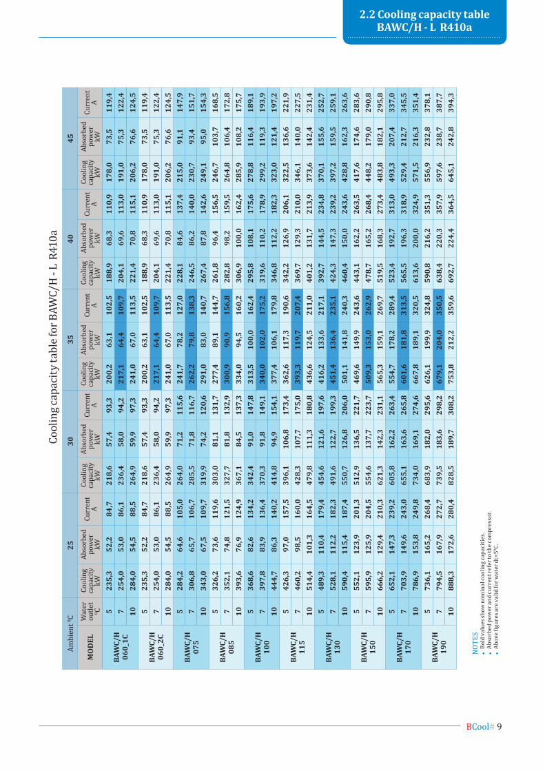
NO
TES
• B
old
valu
es sh
ow n
omin
al co
olin
g cap
acit
ies.
• A
bsor
bed
pow
er a
nd cu
rren
t ref
er to
the c
ompr
esso
r.•
Abo
ve fi
gure
s are
val
id fo
r wat
er d
t=50 C.
2.2 cooling capacity table bAwc/H - L R410a
Ambi
ent 0 C
2530
3540
45
mo
DeL
Wat
er
outle
t 0 C
Cool
ing
capa
city
kW
Abso
rbed
po
wer
kW
Curr
ent
ACo
olin
g ca
paci
ty
kW
Abso
rbed
po
wer
kW
Curr
ent
ACo
olin
g ca
paci
ty
kW
Abso
rbed
po
wer
kW
Curr
ent
ACo
olin
g ca
paci
ty
kW
Abso
rbed
po
wer
kW
Curr
ent
ACo
olin
g ca
paci
ty
kW
Abso
rbed
po
wer
kW
Curr
ent
A
BAW
C/H
060_
1c
523
5,3
52,2
84,7
218,
657
,493
,320
0,2
63,1
102,
518
8,9
68,3
110,
917
8,0
73,5
119,
47
254,
053
,086
,123
6,4
58,0
94,2
217,
164
,410
9,7
204,
169
,611
3,0
191,
075
,312
2,4
1028
4,0
54,5
88,5
264,
959
,997
,324
1,0
67,0
113,
522
1,4
70,8
115,
120
6,2
76,6
124,
5
BAW
C/H
060_
2c
523
5,3
52,2
84,7
218,
657
,493
,320
0,2
63,1
102,
518
8,9
68,3
110,
917
8,0
73,5
119,
47
254,
053
,086
,123
6,4
58,0
94,2
217,
164
,410
9,7
204,
169
,611
3,0
191,
075
,312
2,4
1028
4,0
54,5
88,5
264,
959
,997
,324
1,0
67,0
113,
522
1,4
70,8
115,
120
6,2
76,6
124,
5
BAW
C/H
075
528
4,2
64,6
105,
026
4,0
71,2
115,
624
1,7
78,2
127,
022
8,1
84,6
137,
421
5,0
91,1
147,
97
306,
865
,710
6,7
285,
571
,811
6,7
262,
279
,813
8,3
246,
586
,214
0,0
230,
793
,415
1,7
1034
3,0
67,5
109,
731
9,9
74,2
120,
629
1,0
83,0
140,
726
7,4
87,8
142,
624
9,1
95,0
154,
3
BAW
C/H
085
532
6,2
73,6
119,
630
3,0
81,1
131,
727
7,4
89,1
144,
726
1,8
96,4
156,
524
6,7
103,
716
8,5
735
2,1
74,8
121,
532
7,7
81,8
132,
930
0,9
90,9
156,
828
2,8
98,2
159,
526
4,8
106,
417
2,8
1039
3,6
76,9
124,
936
7,1
84,5
137,
333
4,0
94,5
160,
230
6,9
100,
016
2,4
285,
910
8,2
175,
7
BAW
C/H
100
536
8,6
82,6
134,
234
2,4
91,0
147,
831
3,5
100,
016
2,4
295,
810
8,1
175,
627
8,8
116,
418
9,1
739
7,8
83,9
136,
437
0,3
91,8
149,
134
0,0
102,
017
5,2
319,
611
0,2
178,
929
9,2
119,
319
3,9
1044
4,7
86,3
140,
241
4,8
94,9
154,
137
7,4
106,
117
9,8
346,
811
2,2
182,
332
3,0
121,
419
7,2
BAW
C/H
115
542
6,3
97,0
157,
539
6,1
106,
817
3,4
362,
611
7,3
190,
634
2,2
126,
920
6,1
322,
513
6,6
221,
97
460,
298
,516
0,0
428,
310
7,7
175,
039
3,3
119,
720
7,4
369,
712
9,3
210,
034
6,1
140,
022
7,5
1051
4,4
101,
316
4,5
479,
811
1,3
180,
843
6,6
124,
521
1,0
401,
213
1,7
213,
937
3,6
142,
423
1,4
BAW
C/H
130
548
9,3
110,
417
9,4
454,
612
1,6
197,
641
6,2
133,
621
7,1
392,
714
4,5
234,
837
0,1
155,
625
2,7
752
8,1
112,
218
2,3
491,
612
2,7
199,
345
1,4
136,
423
5,1
424,
314
7,3
239,
239
7,2
159,
525
9,1
1059
0,4
115,
418
7,4
550,
712
6,8
206,
050
1,1
141,
824
0,3
460,
415
0,0
243,
642
8,8
162,
326
3,6
BAW
C/H
150
555
2,1
123,
920
1,3
512,
913
6,5
221,
746
9,6
149,
924
3,6
443,
116
2,2
263,
541
7,6
174,
628
3,6
759
5,9
125,
920
4,5
554,
613
7,7
223,
750
9,3
153,
026
2,9
478,
716
5,2
268,
444
8,2
179,
029
0,8
1066
6,2
129,
421
0,3
621,
314
2,3
231,
156
5,3
159,
126
9,7
519,
516
8,3
273,
448
3,8
182,
129
5,8
BAW
C/H
170
565
2,1
147,
323
9,2
605,
816
2,2
263,
455
4,7
178,
228
9,4
523,
419
2,7
313,
049
3,3
207,
433
7,0
770
3,9
149,
624
3,0
655,
116
3,6
265,
860
1,6
181,
831
3,5
565,
519
6,3
318,
952
9,4
212,
734
5,5
1078
6,9
153,
824
9,8
734,
016
9,1
274,
666
7,8
189,
132
0,5
613,
620
0,0
324,
957
1,5
216,
335
1,4
BAW
C/H
190
573
6,1
165,
226
8,4
683,
918
2,0
295,
662
6,1
199,
932
4,8
590,
821
6,2
351,
355
6,9
232,
837
8,1
779
4,5
167,
927
2,7
739,
518
3,6
298,
267
9,1
204,
035
0,5
638,
422
0,3
357,
959
7,6
238,
738
7,7
1088
8,3
172,
628
0,4
828,
518
9,7
308,
275
3,8
212,
235
9,6
692,
722
4,4
364,
564
5,1
242,
839
4,3
Cool
ing c
apac
ity ta
ble f
or B
AWC/
H -
L R
410a
10 #BCool
Ambi
ent 0 C
-50
27
10
mo
DeL
Wat
er
outle
t 0 C
Hea
ting
capa
city
kW
Abso
rbed
po
wer
kW
Curr
ent
AH
eatin
g ca
paci
ty
kW
Abso
rbed
po
wer
kW
Curr
ent
AH
eatin
g ca
paci
ty
kW
Abso
rbed
po
wer
kW
Curr
ent
AH
eatin
g ca
paci
ty
kW
Abso
rbed
po
wer
kW
Curr
ent
AH
eatin
g ca
paci
ty
kW
Abso
rbed
po
wer
kW
Curr
ent
A
BAW
H
060_
1c
3519
1,8
50,4
90,2
215,
951
,291
,222
9,9
51,6
91,7
251,
052
,292
,528
3,0
56,4
98,5
4018
6,4
55,8
97,6
210,
856
,698
,622
3,9
57,0
99,2
243,
957
,610
0,0
273,
962
,210
6,5
4518
4,3
62,0
106,
120
2,9
65,2
110,
921
7,8
63,0
107,
724
1,5
67,6
114,
226
6,1
68,5
115,
7
BAW
H
060_
2c
3519
1,8
50,4
90,2
215,
951
,291
,222
9,9
51,6
91,7
251,
052
,292
,528
3,0
56,4
98,5
4018
6,4
55,8
97,6
210,
856
,698
,622
3,9
57,0
99,2
243,
957
,610
0,0
273,
962
,210
6,5
4518
4,3
62,0
106,
120
2,9
65,2
110,
921
7,8
63,0
107,
724
1,5
67,6
114,
226
6,1
68,5
115,
7
BAW
H07
5
3523
3,1
62,9
114,
026
2,5
63,9
115,
227
9,5
64,4
115,
930
5,1
65,2
116,
934
4,1
70,4
124,
440
226,
769
,612
3,2
256,
370
,612
4,5
272,
271
,112
5,2
296,
571
,912
6,3
332,
977
,613
4,5
4522
4,0
77,4
134,
024
6,6
81,4
140,
126
4,8
78,7
136,
129
3,6
84,4
144,
332
3,5
85,6
146,
2
BAW
H08
5
3526
6,9
71,9
129,
830
0,6
73,0
131,
232
0,1
73,6
131,
934
9,4
74,4
133,
139
4,0
80,4
141,
640
259,
579
,514
0,3
293,
580
,714
1,8
311,
781
,314
2,6
339,
682
,114
3,9
381,
388
,715
3,1
4525
6,5
88,4
152,
628
2,4
92,9
159,
530
3,3
89,8
154,
933
6,2
96,4
164,
337
0,5
97,7
166,
4
BAW
H10
0
3530
0,8
80,8
145,
633
8,6
82,1
147,
236
0,6
82,7
148,
039
3,7
83,7
149,
344
4,0
90,4
158,
940
292,
489
,415
7,4
330,
790
,715
9,1
351,
191
,416
0,0
382,
692
,416
1,4
429,
699
,717
1,8
4528
9,0
99,4
171,
231
8,2
104,
517
9,0
341,
710
1,0
173,
837
8,8
108,
418
4,3
417,
410
9,9
186,
7
BAW
H11
5
3534
9,7
94,4
171,
039
3,7
95,8
172,
841
9,3
96,6
173,
845
7,7
97,7
175,
351
6,1
105,
618
6,6
4034
0,0
104,
418
4,8
384,
510
6,0
186,
840
8,3
106,
718
7,9
444,
810
7,9
189,
549
9,4
116,
520
1,7
4533
6,0
116,
120
1,1
369,
912
2,0
210,
139
7,2
118,
020
4,1
440,
412
6,6
216,
448
5,3
128,
421
9,2
BAW
H13
0
3540
0,4
107,
819
4,7
450,
810
9,5
196,
848
0,1
110,
319
7,9
524,
111
1,6
199,
659
1,0
120,
621
2,4
4038
9,3
119,
321
0,5
440,
312
1,0
212,
746
7,5
121,
921
3,9
509,
312
3,2
215,
857
1,9
133,
022
9,7
4538
4,8
132,
622
9,0
423,
613
9,4
239,
345
4,9
134,
823
2,4
504,
314
4,6
246,
555
5,7
146,
624
9,7
BAW
H15
0
3545
1,2
121,
221
8,4
508,
112
3,1
220,
854
1,0
124,
122
2,0
590,
612
5,5
223,
966
6,0
135,
623
8,3
4043
8,7
134,
123
6,1
496,
113
6,1
238,
652
6,8
137,
124
0,0
574,
013
8,5
242,
164
4,5
149,
625
7,7
4543
3,6
149,
125
6,8
477,
415
6,7
268,
551
2,6
151,
526
0,7
568,
316
2,6
276,
562
6,3
164,
928
0,1
BAW
H17
0
3553
3,9
143,
725
9,6
601,
114
5,9
262,
464
0,1
147,
126
3,9
698,
814
8,8
266,
278
8,1
160,
828
3,3
4051
9,1
159,
128
0,6
587,
016
1,4
283,
662
3,3
162,
528
5,2
679,
116
4,3
287,
776
2,5
177,
430
6,3
4551
3,0
176,
830
5,3
564,
818
5,9
319,
160
6,5
179,
730
9,9
672,
419
2,8
328,
674
1,0
195,
533
2,9
BAW
H19
0
3560
1,6
161,
629
1,2
677,
416
4,1
294,
472
1,3
165,
429
6,0
787,
516
7,4
298,
688
8,0
180,
831
7,8
4058
4,9
178,
931
4,8
661,
518
1,5
318,
170
2,4
182,
832
0,0
765,
318
4,7
322,
885
9,2
199,
534
3,6
4557
8,1
198,
834
2,5
636,
520
9,0
357,
968
3,4
202,
134
7,6
757,
721
6,8
368,
683
5,0
219,
837
3,4
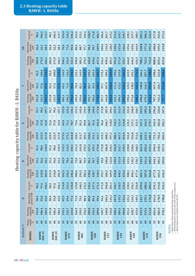
Heat
ing
capa
city
tabl
e for
BAW
H -
L R
410a
NOT
ES•
Bol
d va
lues
show
nom
inal
hea
ting
capa
citi
es.
• A
bsor
bed
pow
er a
nd cu
rren
t ref
er to
the c
ompr
esso
r.•
Abo
ve fi
gure
s are
val
id fo
r wat
er d
t=50 C.
2.3 Heating capacity table bAwH - L R410a
BCool# 11
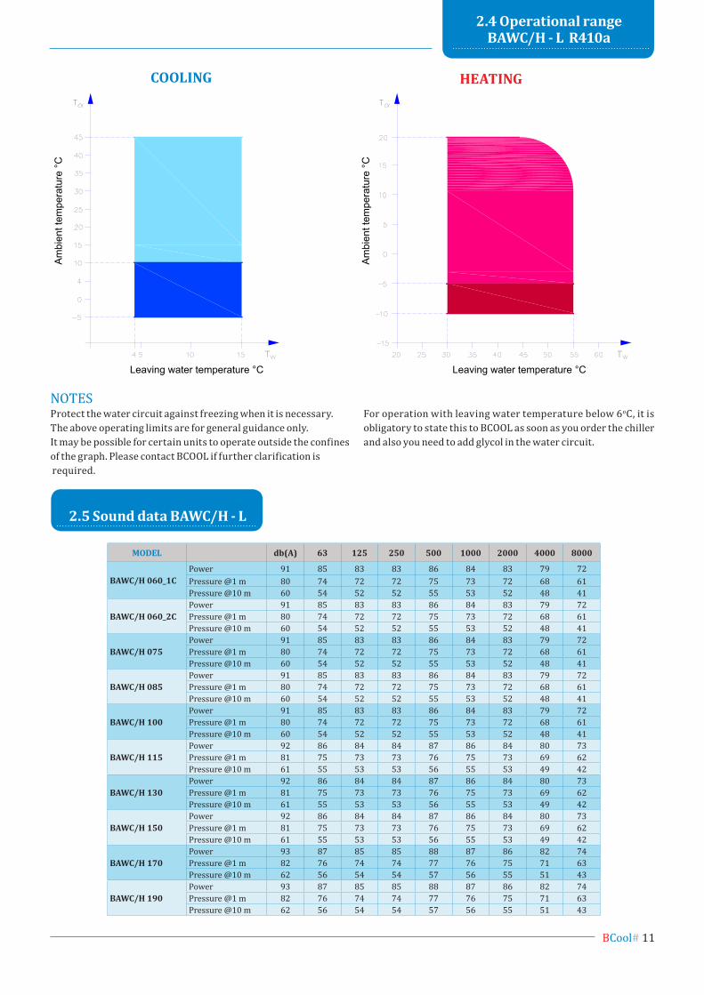
COOLing
moDeL db(Α) 63 125 250 500 1000 2000 4000 8000
bAwc/H 060_1cPower 91 85 83 83 86 84 83 79 72Pressure @1 m 80 74 72 72 75 73 72 68 61Pressure @10 m 60 54 52 52 55 53 52 48 41
bAwc/H 060_2cPower 91 85 83 83 86 84 83 79 72Pressure @1 m 80 74 72 72 75 73 72 68 61Pressure @10 m 60 54 52 52 55 53 52 48 41
bAwc/H 075Power 91 85 83 83 86 84 83 79 72Pressure @1 m 80 74 72 72 75 73 72 68 61Pressure @10 m 60 54 52 52 55 53 52 48 41
bAwc/H 085Power 91 85 83 83 86 84 83 79 72Pressure @1 m 80 74 72 72 75 73 72 68 61Pressure @10 m 60 54 52 52 55 53 52 48 41
bAwc/H 100Power 91 85 83 83 86 84 83 79 72Pressure @1 m 80 74 72 72 75 73 72 68 61Pressure @10 m 60 54 52 52 55 53 52 48 41
bAwc/H 115Power 92 86 84 84 87 86 84 80 73Pressure @1 m 81 75 73 73 76 75 73 69 62Pressure @10 m 61 55 53 53 56 55 53 49 42
bAwc/H 130Power 92 86 84 84 87 86 84 80 73Pressure @1 m 81 75 73 73 76 75 73 69 62Pressure @10 m 61 55 53 53 56 55 53 49 42
bAwc/H 150Power 92 86 84 84 87 86 84 80 73Pressure @1 m 81 75 73 73 76 75 73 69 62Pressure @10 m 61 55 53 53 56 55 53 49 42
bAwc/H 170Power 93 87 85 85 88 87 86 82 74Pressure @1 m 82 76 74 74 77 76 75 71 63Pressure @10 m 62 56 54 54 57 56 55 51 43
bAwc/H 190Power 93 87 85 85 88 87 86 82 74Pressure @1 m 82 76 74 74 77 76 75 71 63Pressure @10 m 62 56 54 54 57 56 55 51 43
2.4 operational range bAwc/H - L R410a
2.5 sound data bAwc/H - L
Ambi
ent t
empe
ratu
re °C
Leaving water temperature °C Leaving water temperature °CAm
bien
t tem
pera
ture
°C
HeAting
NOTESProtect the water circuit against freezing when it is necessary.The above operating limits are for general guidance only.It may be possible for certain units to operate outside the confines of the graph. Please contact BCOOL if further clarification is required.
For operation with leaving water temperature below 6oC, it is obligatory to state this to BCOOL as soon as you order the chiller and also you need to add glycol in the water circuit.
12 #BCool
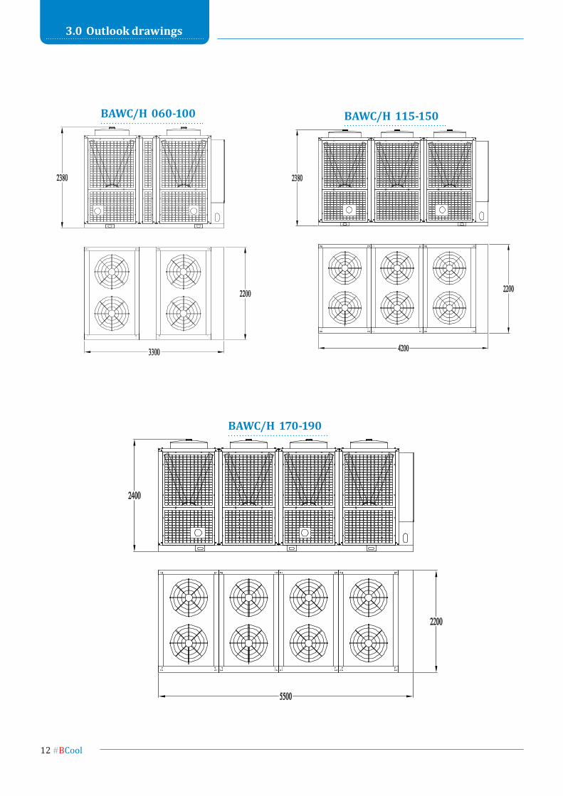
3.0 outlook drawings
bAwc/H 060-100 bAwc/H 115-150
bAwc/H 170-190
BCool# 13
4.0 Hydraulic circuits
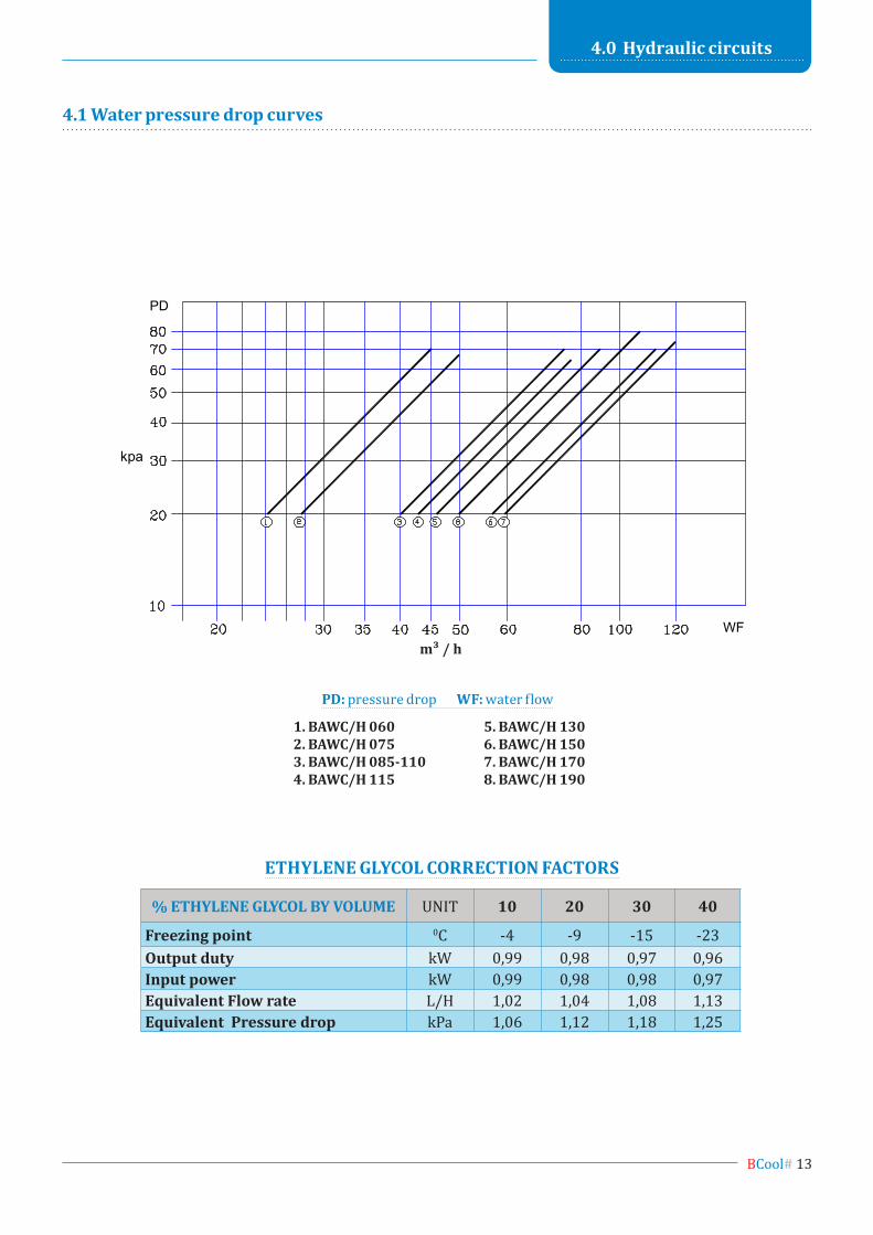
4.1 water pressure drop curves
PD
WF
kpa
m/h3
1. bAwc/H 0602. bAwc/H 0753. bAwc/H 085-1104. bAwc/H 115
5. bAwc/H 1306. bAwc/H 1507. bAwc/H 1708. bAwc/H 190
pD: pressure drop wf: water flow
% eTHyLene gLycoL by VoLume UNIT 10 20 30 40
freezing point 0C -4 -9 -15 -23Output duty kW 0,99 0,98 0,97 0,96input power kW 0,99 0,98 0,98 0,97equivalent flow rate L/H 1,02 1,04 1,08 1,13equivalent pressure drop kPa 1,06 1,12 1,18 1,25
eTHyLene gLycoL coRRecTion fAcToRs
m³ / h
14 #BCool
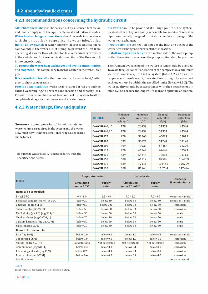
moDeLMinimum
water volume (l)
Minimum water flow
(l/h)
Nominal water flow
(l/h)
Maximum water flow
(l/h)
bAwc/H 060_1c 778 26132 37331 45544bAwc/H 060_2c 778 26132 37331 45544bAwc/H 075 470 31566 45094 55015bAwc/H 085 539 36221 51744 63128bAwc/H 100 609 40926 58466 71329bAwc/H 115 470 47349 67642 82523bAwc/H 130 539 54344 77634 94713bAwc/H 150 608 61312 87589 106859bAwc/H 170 539 72415 103450 126209bAwc/H 190 608 81749 116784 142476
4.2.1 Recommendations concerning the hydraulic circuit
to ensure proper operation of the unit, a minimum water volume is required in the system and the water flow must be within the operational range, as specified in the tables.
4.2.2 water charge, flow and quality
All field connections must be carried out by a licensed technician and must comply with the applicable local and national codes.water heat exchanger connections should be made in accordance w it h t he unit out look , respec t ing t he water in let/out let .install a flow switch or water differential pressostat (standardcomponent) in the water outlet piping, to prevent the unit fromoperating at a water flow which is too low. A terminal is providedin the switch box, for the electrical connection of the f low switch inthe control circuit.To protect the water heat exchanger and avoid contamination and fragment, it is compulsory to install a filter in the water inlet pipe.it is essential to install a thermometer in the water inlet/outlet pipe, to check temperatures.provide heat insulation with suitable vapor barrier around the chilled water piping, to prevent condensation and capacity loss. Provide drain connections at all low points of the system, to allow complete drainage for maintenance and / or shutdown.
Air vents should be provided at all high points of the system, located where they are easily accessible for service. The water pipes are specially designed to obtain a complete air purge of the water heat exchanger.provide f lexible connection pipes at the inlet and outlet of the water heat exchanger, to prevent tubes vibration.install an expansion tank on the suction side of the water pump, so that the water pressure on the pump suction shall be positive.
The frequent evacuation of the water system should be avoided. To avoid frequent on/off operation of the compressor, a minimum water volume is required in the system (table 4.2.2). To assure proper operation of the unit, the water flow through the water heat exchanger must be within the specified limits (in table 4.2.2). The water quality should be in accordance with the specifications in table 4.2.2, to ensure the longest life span and optimum operation.
Be sure the water quality is in accordance with the specifications below.
4.2 About hydraulic circuits
iTemsevaporator water Heated water
tendencyif out of criteriaCirculating
water 20oCSupplywater
Circulatingwater 20 - 60oC
Supplywater
items to be controlled:
PH AT 25oC 6.8 - 8.0 6.8 - 8.0 7.0 - 8.0 7.0 - 8.0 corrosion + scaleElectrical conduct (mS/m) at 25oC below 30 below 30 below 30 below 30 corrosion + scaleChloride ion (mg CI-/I) below 50 below 200 below 30 below 30 corrosionSulfate ion (mg SO 2/4/I below 50 below 50 below 30 below 30 corrosionM-alkalinity (ph 4.8) (mg SO3/I) below 50 below 50 below 50 below 50 scaleTotal hardness (mg CaCO3/I ) below 70 below 70 below 70 below 70 scaleCalcium hardness (mg CaCO3/I) below 50 below 50 below 50 below 50 scaleSilica ion (mg SiO2/I below 30 below 30 below 30 below 30 scaleitems to be referred to:Iron (mg Fe/I) below 1.0 below 0.3 below 1.0 below 0.3 corrosion + scaleCopper (mg Cu/I) below 1.0 below 0.1 below 1.0 below 1.0 corrosionSulfide ion (mg S2-/I) Not detectable Not detectable Not detectable Not detectable corrosionAmonium ion (mg NH+4/I below 0.3 below 0.1 below 0.1 below 0.1 corrosionRemaining chloride (mg CI/I) below 0.25 below 0.3 below 0.1 below 0.3 corrosionFree carbide (mg SO2/I) below 0.4 below 4.0 below 0.4 below 4.0 corrosionStability index - - - - corrosion + scale
NOTESThe above tables are purely indicative and non-binding.
BCool# 15
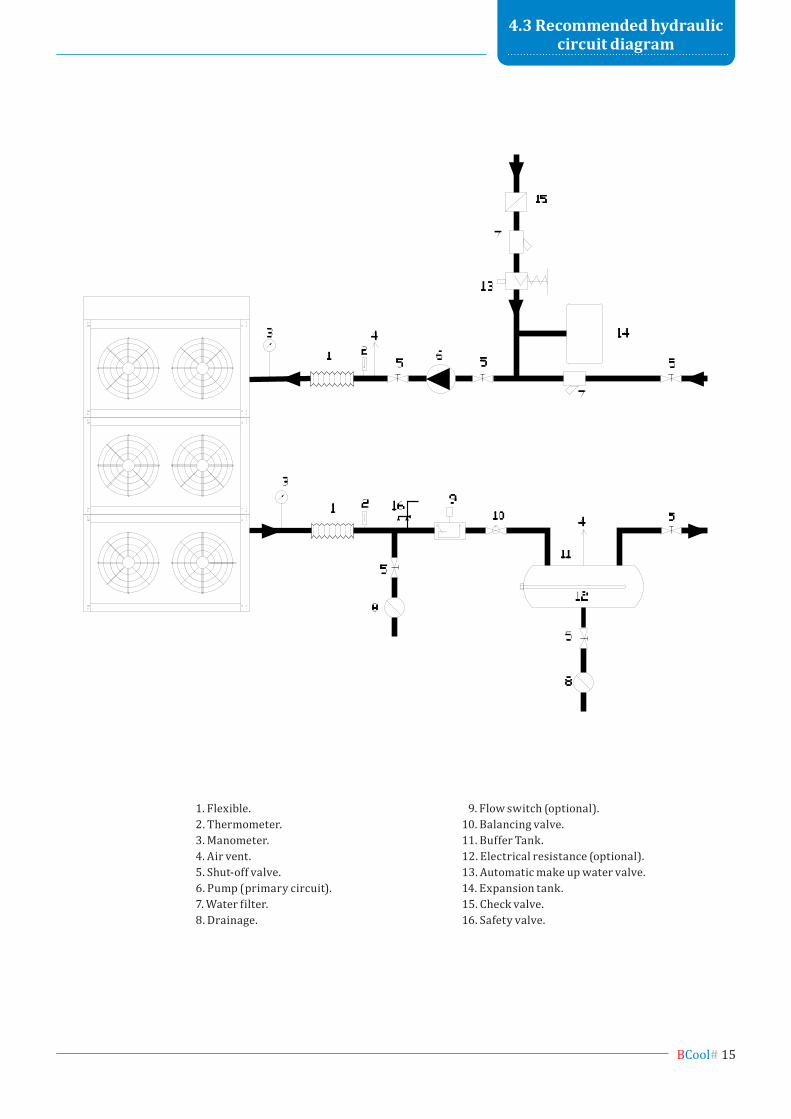
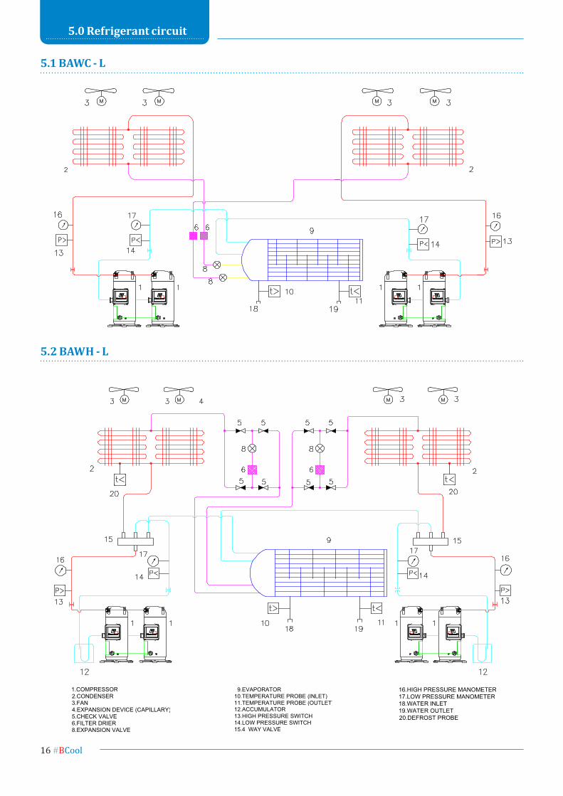
1. Flexible. 2. Thermometer. 3. Manometer. 4. Air vent. 5. Shut-off valve. 6. Pump (primary circuit). 7. Water filter. 8. Drainage.
9. Flow switch (optional).10. Balancing valve.11. Buffer Tank.12. Electrical resistance (optional).13. Automatic make up water valve. 14. Expansion tank.15. Check valve.16. Safety valve.
4.3 Recommended hydrauliccircuit diagram
16 #BCool
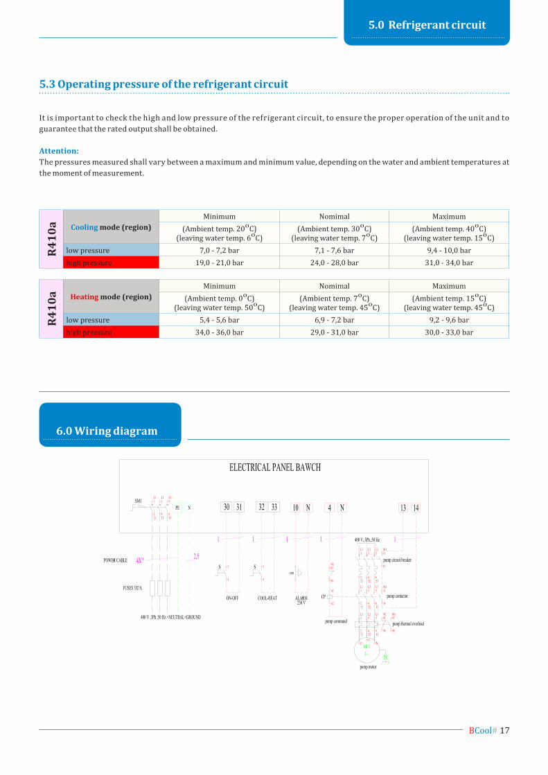
5.0 Refrigerant circuit
5.1 bAwc - L
5.2 bAwH - L
BCool# 17
5.0 Refrigerant circuit
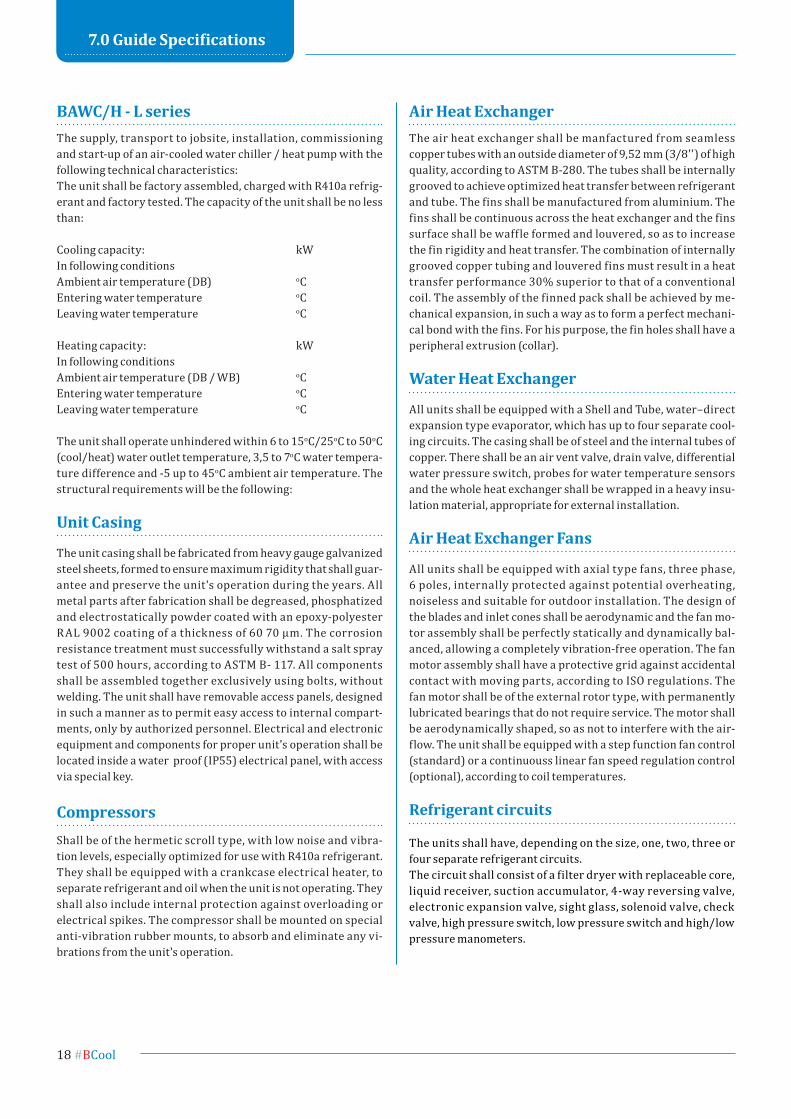
6.0 wiring diagram
It is important to check the high and low pressure of the refrigerant circuit, to ensure the proper operation of the unit and to guarantee that the rated output shall be obtained.
Attention:The pressures measured shall vary between a maximum and minimum value, depending on the water and ambient temperatures at the moment of measurement.
5.3 operating pressure of the refrigerant circuit
R410
a Cooling mode (region)Minimum Nomimal Maximum
(Ambient temp. 200C)(leaving water temp. 60C)
(Ambient temp. 300C)(leaving water temp. 70C)
(Ambient temp. 400C)(leaving water temp. 150C)
low pressure 7,0 - 7,2 bar 7,1 - 7,6 bar 9,4 - 10,0 barhigh pressure 19,0 - 21,0 bar 24,0 - 28,0 bar 31,0 - 34,0 bar
R410
a Heating mode (region)Minimum Nomimal Maximum
(Ambient temp. 00C)(leaving water temp. 500C)
(Ambient temp. 70C)(leaving water temp. 450C)
(Ambient temp. 150C)(leaving water temp. 450C)
low pressure 5,4 - 5,6 bar 6,9 - 7,2 bar 9,2 - 9,6 barhigh pressure 34,0 - 36,0 bar 29,0 - 31,0 bar 30,0 - 33,0 bar
18 #BCool
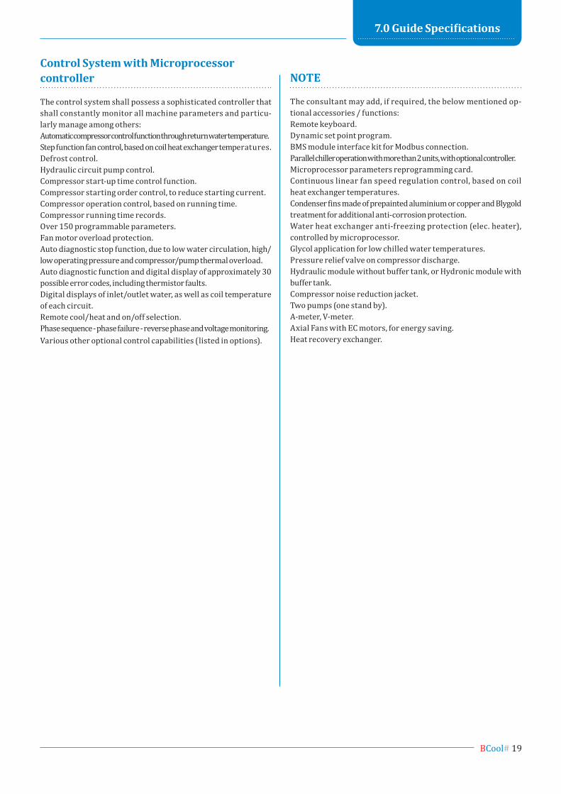
7.0 guide specifications
BAWC/H - L seriesThe supply, transport to jobsite, installation, commissioning and start-up of an air-cooled water chiller / heat pump with the following technical characteristics:The unit shall be factory assembled, charged with R410a refrig-erant and factory tested. The capacity of the unit shall be no less than:
Cooling capacity: kWIn following conditionsAmbient air temperature (DB) oC Entering water temperature oC Leaving water temperature oC
Heating capacity: kWIn following conditionsAmbient air temperature (DB / WB) oC Entering water temperature oC Leaving water temperature oC
The unit shall operate unhindered within 6 to 15oC/25oC to 50oC (cool/heat) water outlet temperature, 3,5 to 7oC water tempera-ture difference and -5 up to 45oC ambient air temperature. The structural requirements will be the following:
Unit Casing
The unit casing shall be fabricated from heavy gauge galvanized steel sheets, formed to ensure maximum rigidity that shall guar-antee and preserve the unit's operation during the years. All metal parts after fabrication shall be degreased, phosphatized and electrostatically powder coated with an epoxy-polyester RAL 9002 coating of a thickness of 60 70 μm. Τhe corrosion resistance treatment must successfully withstand a salt spray test of 500 hours, according to ASTM B- 117. All components shall be assembled together exclusively using bolts, without welding. The unit shall have removable access panels, designed in such a manner as to permit easy access to internal compart-ments, only by authorized personnel. Electrical and electronic equipment and components for proper unit's operation shall be located inside a water proof (IP55) electrical panel, with access via special key.
CompressorsShall be of the hermetic scroll type, with low noise and vibra-tion levels, especially optimized for use with R410a refrigerant. They shall be equipped with a crankcase electrical heater, to separate refrigerant and oil when the unit is not operating. They shall also include internal protection against overloading or electrical spikes. The compressor shall be mounted on special anti-vibration rubber mounts, to absorb and eliminate any vi-brations from the unit's operation.
Air Heat exchangerThe air heat exchanger shall be manfactured from seamless copper tubes with an outside diameter of 9,52 mm (3/8'') of high quality, according to ASTM B-280. The tubes shall be internally grooved to achieve optimized heat transfer between refrigerant and tube. The fins shall be manufactured from aluminium. The fins shall be continuous across the heat exchanger and the fins surface shall be waffle formed and louvered, so as to increase the fin rigidity and heat transfer. The combination of internally grooved copper tubing and louvered fins must result in a heat transfer performance 30% superior to that of a conventional coil. The assembly of the finned pack shall be achieved by me-chanical expansion, in such a way as to form a perfect mechani-cal bond with the fins. For his purpose, the fin holes shall have a peripheral extrusion (collar).
water Heat exchanger
All units shall be equipped with a Shell and Tube, water–direct expansion type evaporator, which has up to four separate cool-ing circuits. The casing shall be of steel and the internal tubes of copper. There shall be an air vent valve, drain valve, differential water pressure switch, probes for water temperature sensors and the whole heat exchanger shall be wrapped in a heavy insu-lation material, appropriate for external installation.
Air Heat exchanger fans
All units shall be equipped with axial type fans, three phase, 6 poles, internally protected against potential overheating, noiseless and suitable for outdoor installation. The design of the blades and inlet cones shall be aerodynamic and the fan mo-tor assembly shall be perfectly statically and dynamically bal-anced, allowing a completely vibration-free operation. The fan motor assembly shall have a protective grid against accidental contact with moving parts, according to ISO regulations. The fan motor shall be of the external rotor type, with permanently lubricated bearings that do not require service. The motor shall be aerodynamically shaped, so as not to interfere with the air-flow. The unit shall be equipped with a step function fan control (standard) or a continuouss linear fan speed regulation control (optional), according to coil temperatures.
Refrigerant circuits
The units shall have, depending on the size, one, two, three or four separate refrigerant circuits.The circuit shall consist of a filter dryer with replaceable core, liquid receiver, suction accumulator, 4-way reversing valve, electronic expansion valve, sight glass, solenoid valve, check valve, high pressure switch, low pressure switch and high/low pressure manometers.
BCool# 19
7.0 guide specifications
control system with microprocessor controller
The control system shall possess a sophisticated controller that shall constantly monitor all machine parameters and particu-larly manage among others:Automatic compressor control function through return water temperature.Step function fan control, based on coil heat exchanger temperatures.Defrost control.Hydraulic circuit pump control.Compressor start-up time control function.Compressor starting order control, to reduce starting current.Compressor operation control, based on running time.Compressor running time records.Over 150 programmable parameters.Fan motor overload protection.Auto diagnostic stop function, due to low water circulation, high/low operating pressure and compressor/pump thermal overload.Auto diagnostic function and digital display of approximately 30 possible error codes, including thermistor faults.Digital displays of inlet/outlet water, as well as coil temperature of each circuit.Remote cool/heat and on/off selection.Phase sequence - phase failure - reverse phase and voltage monitoring.Various other optional control capabilities (listed in options).
nOte
The consultant may add, if required, the below mentioned op-tional accessories / functions:Remote keyboard.Dynamic set point program.BMS module interface kit for Modbus connection.Parallel chiller operation with more than 2 units, with optional controller.Microprocessor parameters reprogramming card.Continuous linear fan speed regulation control, based on coil heat exchanger temperatures.Condenser fins made of prepainted aluminium or copper and Blygold treatment for additional anti-corrosion protection.Water heat exchanger anti-freezing protection (elec. heater), controlled by microprocessor.Glycol application for low chilled water temperatures.Pressure relief valve on compressor discharge.Hydraulic module without buffer tank, or Hydronic module with buffer tank.Compressor noise reduction jacket.Two pumps (one stand by).A-meter, V-meter.Axial Fans with EC motors, for energy saving.Heat recovery exchanger.

b cooL mAnufAcTuReRs of AiR-conDiTioning eQuipmenT LTDomirou & Andromachis str., mandra, Attica, Zip: 19 600, greecephone: +30 211 0124898-9 fax: +30 211 2159181
office of north greece: 27, m. Alexandrou str., pylaia, Thessaloniki, Zip: 55 535phone: +30 2316 007072 fax: +30 2316 007073
web: www.bcool.com.gr e-mail: [email protected]
“BCOOL reserves the right to change specifications without prior notice”