Embed Size (px)
Citation preview

Scrum and Requirements
SOE MM3
Scrum
Larman Ch. 7
Start
Scrum Model
A small group is responsible for picking up the ball and moving it toward the goal.
Goal
SCRUM Practices
Product Backlog
Sprint
Sprint Planning Meeting
Sprint Backlog
Roles
Product Owner, Scrum Master, Scrum Team
Daily Scrum Meeting
Sprint Review Meeting

30 days
24 hours
Product Backlog
As prioritized by Product Owner
Sprint Backlog
Backlog tasks
expanded
by team
Potentially Shippable
Product Increment
Daily Scrum
Meeting
Scrum Lifecycle
Product Backlog
Prioritized list of work to be performed on a product
Anyone can contribute backlog items
Product Owner responsible for prioritisation

Sprint
A fixed period of 30 days to develop a deliverable product
The Sprint includes design, coding, testing, and documentation
Once a Sprint has started only the Scrum Team can add or remove items in Sprint backlog
Abnormal termination of Sprint is called for when the Sprint Goal no longer makes sense
Meeting to set the next Sprint goal
ProductBacklog
Team
Capabilities
Business
Conditions
Technology
Stability
Executable
Product
Increment
ReviewConsiderOrganize
Next SprintGoal
Sprint Backlog
Sprint Planning
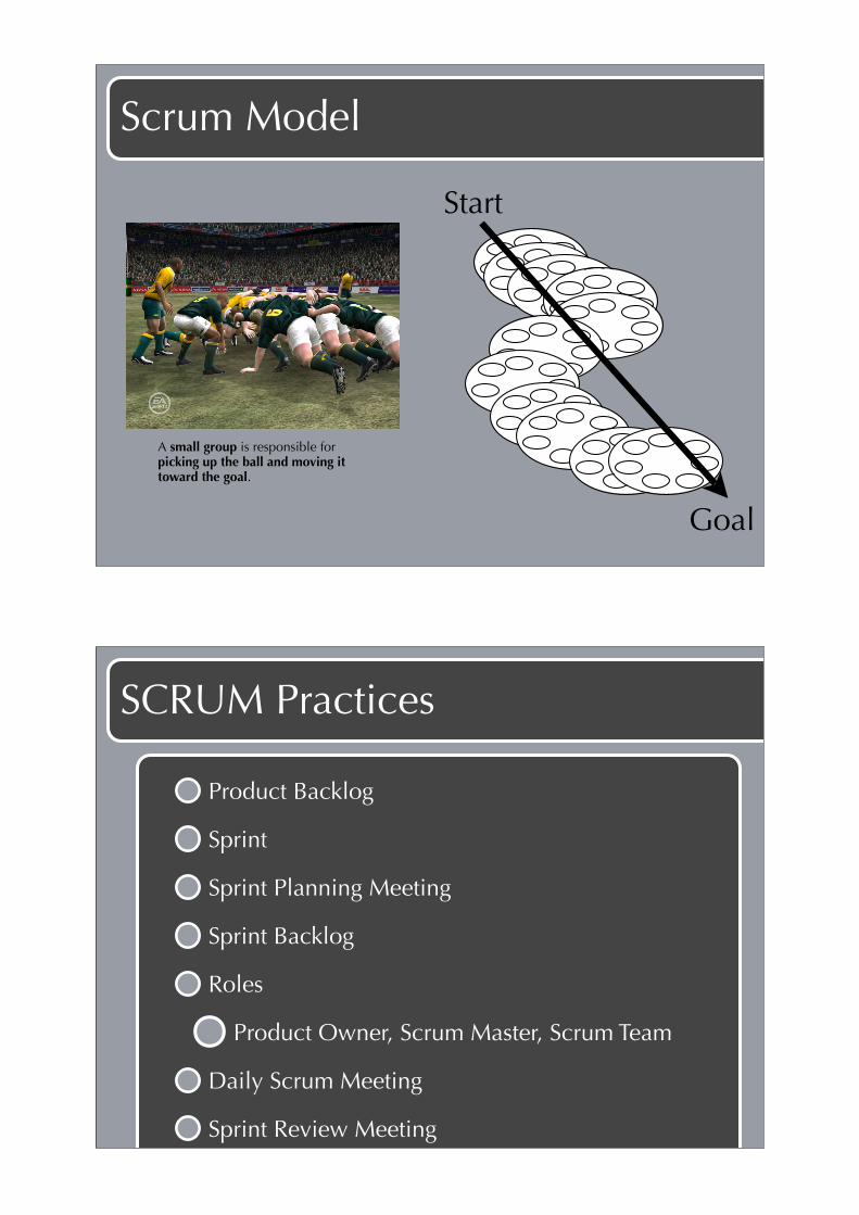
Progress
752 762
664619
304264
180
104
200
100
200
300
400
500
600
700
800
900
04/05/06
06/05/06
08/05/06
10/05/06
12/05/06
14/05/06
16/05/06
18/05/06
20/05/06
22/05/06
24/05/06
26/05/06
28/05/06
30/05/06
01/06/06
Date
Rem
ain
ing
Eff
ort
in
Ho
urs
Sprint Burndown Chart
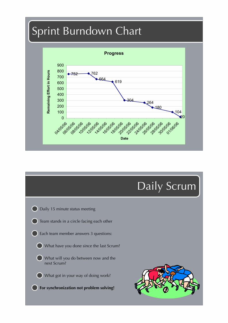
Daily Scrum
Daily 15 minute status meeting
Team stands in a circle facing each other
Each team member answers 3 questions:
What have you done since the last Scrum?
What will you do between now and the next Scrum?
What got in your way of doing work?
For synchronization not problem solving!
Sprint Review
During this meeting the team presents to management, customers, users and the Product Owner the product increment that has been built during the Sprint
The team tells the story of its journey during the Sprint.
Powerpoint presentations are forbidden!
Scrum Team
Self-organizing
Cross-functional with no roles
Seven plus or minus two
Responsible for committing to work
Authority to do whatever is needed to meet commitment
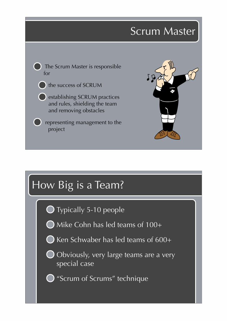
Chickens & Pigs
Members of Scrum Team are known as Pigs because they are committed to delivering Sprint Goal
People who are involved but not dedicated to the project are known as Chickens - they attend Scrum meetings as observers
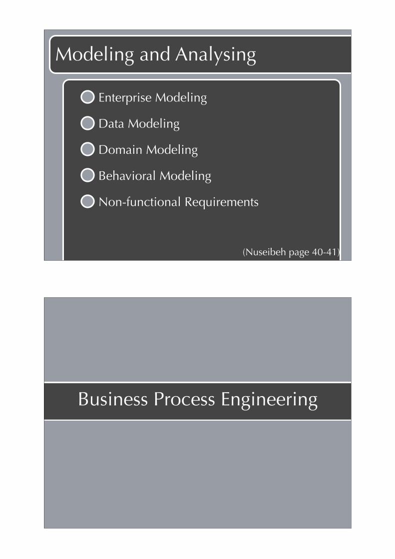
Product Owner
Sets development schedule by prioritizing backlog
One person in this role ensures that only one set of requirements drives development
Can be influenced by committees, management, customers, sales people, but is the only person that prioritizes
Works with others to estimate items on Product Backlog
Eliminates confusion of multiple bosses, different opinions, and interference
Scrum Master
The Scrum Master is responsible for
the success of SCRUM
establishing SCRUM practices and rules, shielding the teamand removing obstacles
representing management to the project
How Big is a Team?
Typically 5-10 people
Mike Cohn has led teams of 100+
Ken Schwaber has led teams of 600+
Obviously, very large teams are a very special case
“Scrum of Scrums” technique

Software Requirements
SWEBOK Ch. 2
! "#"! !"#$$$"%"&''(")*+,-./"
$%&'()*(+! *,! $,-*./0(! ),1-23%0/*2,1!),1*0,4! /1+!5/1/3(+!
,6(0!*7(!(1*20(!$,-*./0(!42-(!)8)4(9!:;,*<<=!>-4<?=!@,5<A=!
B7/CDE!
01&1 2+.3456"7/3"2+.5*,,"8*94-+*:*/6,"
F! +2$*21)*2,1! )/1! &(! +0/.1! &(*.((1! ;+.3456" G/0/5(*(0$!
/1+ ;+.5*,," G/0/5(*(0$9! >0,+%)*! G/0/5(*(0$! /0(!
0(H%20(5(1*$! ,1! $,-*./0(! *,! &(! +(6(4,G(+! I-,0! (J/5G4(K!
LB7(! $,-*./0(! $7/44! 6(02-8! *7/*! /! $*%+(1*! 5((*$! /44!
G0(0(H%2$2*($!&(-,0(!7(!,0!$7(!0(32$*(0$!-,0!/!),%0$(9MN9!
F! G0,)($$! G/0/5(*(0! 2$! ($$(1*2/448! /! ),1$*0/21*! ,1! *7(!
+(6(4,G5(1*!,-!*7(!$,-*./0(!I-,0!(J/5G4(K!LB7(!$,-*./0(!
$7/44!&(!.02**(1!21!F+/9MN9!B7($(!/0(!$,5(*25($!O1,.1!/$!
G0,)($$!0(H%20(5(1*$9!
@,5(! $,-*./0(! 0(H%20(5(1*$! 3(1(0/*(! 25G42)2*! G0,)($$!
0(H%20(5(1*$9!B7(!)7,2)(!,-!6(02-2)/*2,1! *()712H%(!2$!,1(!
(J/5G4(9! F1,*7(0! 5237*! &(! *7(! %$(! ,-! G/0*2)%4/048!
023,0,%$!/1/48$2$!*()712H%($!I$%)7!/$!-,05/4!$G()2-2)/*2,1!
5(*7,+$N! *,! 0(+%)(! -/%4*$! .72)7! )/1! 4(/+! *,! 21/+(H%/*(!
0(42/&242*89! >0,)($$! 0(H%20(5(1*$! 5/8! /4$,! &(! 25G,$(+!
+20()*48!&8!*7(!+(6(4,G5(1*!,03/12P/*2,1K!*7(20!)%$*,5(0K!
,0!/!*720+!G/0*8!$%)7!/$!/!$/-(*8!0(3%4/*,0!:;,*<<=!@,5CDE9!
!"#$%&'(!Q0(/O+,.1!,-!*,G2)$!-,0!*7(!@,-*./0(!R(H%20(5(1*$!;F!
01<1 =4/56-./7>"7/3"?./@4/56-./7>"8*94-+*:*/6,"
=4/56-./7>! 0(H%20(5(1*$! +($)02&(! *7(! -%1)*2,1$! *7/*! *7(!
$,-*./0(!2$!*,!(J()%*(=!-,0!(J/5G4(K!-,05/**213!$,5(!*(J*!
,0! 5,+%4/*213! /! $231/49! B7(8! /0(! $,5(*25($! O1,.1! /$!
)/G/&242*2($9!!
?./@4/56-./7>! 0(H%20(5(1*$! /0(! *7(! ,1($! *7/*! /)*! *,!
),1$*0/21! *7(! $,4%*2,19! S,1-%1)*2,1/4! 0(H%20(5(1*$! /0(!
$,5(*25($!O1,.1!/$!),1$*0/21*$!,0!H%/42*8! 0(H%20(5(1*$9!
B7(8!)/1!&(! -%0*7(0!)4/$$2-2(+!/)),0+213! *,!.7(*7(0! *7(8!
/0(! G(0-,05/1)(! 0(H%20(5(1*$K! 5/21*/21/&242*8!
0(H%20(5(1*$K! $/-(*8! 0(H%20(5(1*$K! 0(42/&242*8!
0(H%20(5(1*$K! ,0! ,1(! ,-! 5/18! ,*7(0! *8G($! ,-! $,-*./0(!
0(H%20(5(1*$9! B7($(! *,G2)$! /0(! /4$,! +2$)%$$(+! 21! *7(!
@,-*./0(!T%/42*8!;F9!:;,*<<=!@,5CDE!
SWEBOK 2004

Requirements Formulation
Establishsystem needs
Feasibilitystudy
Systemmodeling
Requirementsdefinition
Requirementsspecification
Needs report Feasibilityreport
System model Definitionof requirements
Specificationof requirements
Requirementsdocument
Nuseibeh on Requirements Eng.
Quoting Zave (1983)
“Requirements engineering is the branch of software engineering concerned with the real-world goals for, functions of, and constraints on software systems. It is also concerned with the relationship of these factors to precise specifications of software behavior, and to their evolution over time and across software families."
(Nuseibeh page 37)

Requirements Engineering Terms
Process - instance of a process model
Technique
Method
(Nuseibeh page 39)
Eliciting Requirements
Boundaries, stakeholders, goals
Elicitation techniques:
data gathering, brainstorming, prototyping, model-driven (goals or scenarios), cognitive (think aloud, card sorting), contextual techniques
(Nuseibeh page 39-40)
Modeling and Analysing
Enterprise Modeling
Data Modeling
Domain Modeling
Behavioral Modeling
Non-functional Requirements
(Nuseibeh page 40-41)
Business Process Engineering

Uses an integrated set of procedures, methods, and tools to identify how information systems can best meet the strategic goals of an enterprise
Focuses first on the enterprise and then on the business area
Creates enterprise models, data models and process models
Creates a framework for better information management distribution, and control
BPE Hierarchy
InformationStrategy Planning
(World view)
Business AreaAnalysis
(Domain view)
Business SystemDesign
(Element view)
Construction &
Integration(Detailed view)
The enterprise
business area
Processingrequirement
A business
area
Softwareengineer
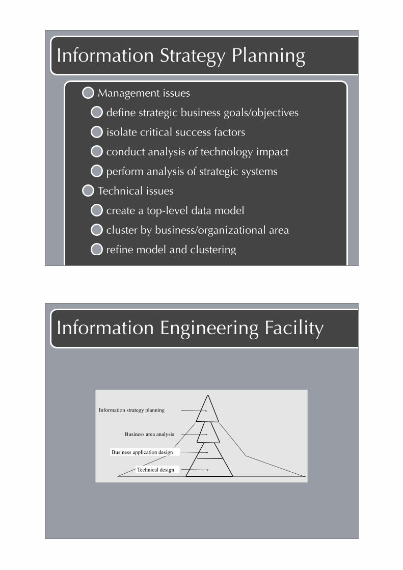
Information Strategy Planning
Management issues
define strategic business goals/objectives
isolate critical success factors
conduct analysis of technology impact
perform analysis of strategic systems
Technical issues
create a top-level data model
cluster by business/organizational area
refine model and clustering
Information Engineering Facility
Information strategy planning
Business area analysis
Business application design
Technical design

IEF - Information planning
Matrices
Pro
du
cin
g
Customer
C = CreateR = ReadU = UpdateD = Delete
Entity Types
Order
Order Line
Product
Part
Supplier
Warehouse M
ark
etin
g
Cu
sto
mer
reg
istr
atio
n
Acc
ept
Ord
er
Ch
ang
e O
rder
Can
cel
ord
er
Bu
sin
ess
Fu
nct
ion
s
C
U
D
R
U
D
IEF - Analysis: ERD
Customer
Product
Supplier Part
Order Warehouse
Order line
Places Consists of
Mentions
Su
pp
lies
Is stored in
Sto
red in
Consists of
Supplies

IEF - Analysis: Process Hierarchy
Runningthe company
Marketing
Selling
Customerregistration
Orderprocessing
Acceptorder
Changeorder
Cancelorder
Producing
IEF - Analysis: Process Handling
Process:! ACCEPT ORDER! ACCEPT ORDER! ! IMPORTS:! Entity View to_be_ordered_product! ! ! ! ! ...........! ! EXPORTS:! Entity View confirmed order_line! ! ! ! ! ...........! ! ENTITY ACTIONS:!Entity View confirmed order_line! ! ! ! ! ! ! ...........! ! ! ! READ to_be_controlled product! ! ! ! ! WITH name EQUAL TO to_be_ordered product name! ! ! ! WHEN not found! ! ! ! ESCAPE! ! ! ! ! ...........! ! ! ! ! CREATE confirmed order! ! ! ! ! SET date TO "system date"! ! ! ! ! SET number TO "next free value"! ! ! ! ! ASSOCIATE WITH to_be_controlled customer WHICH places IT! ! ! ! ! ASSOCIATE WITH confirmed order_line WHICH details IT! ! ! ! ! WHEN already exists! ! ! ! ! ! .........
! ! ! ! ! MOVE confirmed order TO accepted order,
Business Process Engineering

IEF: From Analysis to Code
InformationStrategyPlanning
BusinessAreaAnalysis
Business SystemDesign
TechnicalDesign
A
xxx xxx xxxx x x x x
xxx xxx xxxx x x x x
A
Database generering Kode-generering
1-5
12-16
17
6-11
Database generation Code generation
IEF: From Analysis to Code
Information Strategy Planning:
1 Matrix Processor
2 Organizational Hierarchy Diagram
3 Subject Area Diagram
4 Function Hierarchy Diagram
5 Function Dependency Diagram
Business System Design:
12!Dialog Flow Diagram
13!Screen Design
14!Prototyping
15!Procedure Action Diagram
16!Structure Chart
Technical Design:
17!Data Structure Diagram
Business Area Analysis:
6 Entity Relationship Diagram
7 Process Hierarchy Diagram
8 Process Dependency Diagram
9 Process Action Diagram
10!Structure Chart
11!Matrix Processor
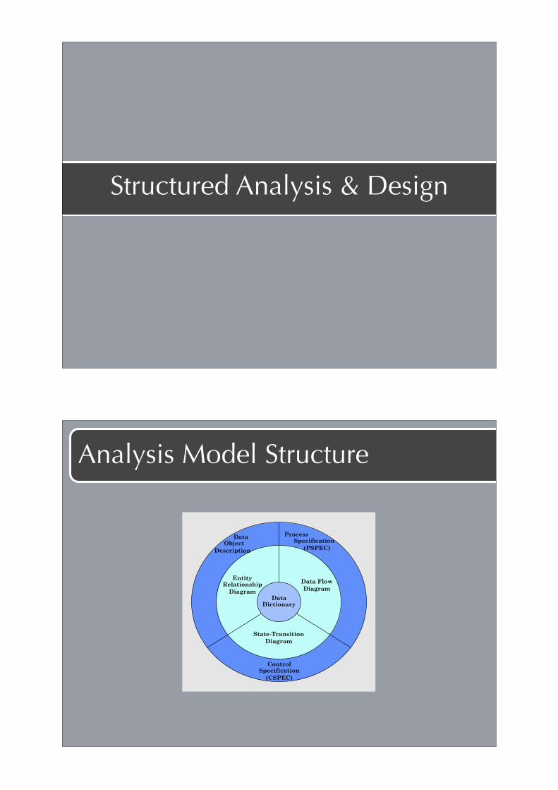
Structured Analysis & Design
Analysis Model Structure
Data Object
Description
Process Specification
(PSPEC)
ControlSpecification
(CSPEC)
EntityRelationship
Diagram
Data Flow
Diagram
State-Transition
Diagram
Data Dictionary

The Functional Model: The DFD
process
externalentity
dataitem
event flow,control item
data/control store
A terminator is a producer or a consumer of data flows
number address
streetaddress
city
state
postcode
a data store is a place where data values can be stored and retrieved later
Structured Analysis
The environmental model
Statement of purpose
Context diagram
Event list
The behavioral model
Data flow diagrams
Process Specification

Statement of Purpose
A brief, concise textual statement of the purpose of the system.
Clarifies the boundaries of the system - what will be taken care of by the system, and what will not?
Journal administration:The computer based system is used for administration of the information necessary to publish the Scandinavian Journal of Information Systems (SJIS). This includes registration of new subscribers, billing, mailing, and registration of subscriber data.
Context Diagram
SJIS
Subscribers
Bookkeeping Bank
Agents
Payments
Balance
Issues
Pay- ment
Orders
Invoices
Money transfer
Terminators
New sub- scriber

The Event List
1. Person or institution enters subscription.
2. Agent enters subscription on behalf of a person or institution.
3. The bank reports a money transfer.
4. Bookkeeping receives details on payments.
5. Agent cancels subscription.
6. Issue is sent to subscriber.
7. Invoice is sent to agent.
8. Invoice is sent to subscriber directly.
9. Subscription is cancelled.
10. Subscriber pays amount due
11. .....
A list of the "stimuli" that occur in the outside world and to which the system must respond.
Subscriber pays amount due
Payment
Transactions
Registrationof
payments
Subscriber
Issuing data
Subscriberdata
Bookkeeping
Debit
Termination
Subscriber file

Responses In One Diagram
Upward Leveling of Diagrams
=
12
3
4
5
6
12
3
.6
.5
.47
Processes 4, 5, and 6 are united into a new process 7. Processes 4, 5, and 6 are pushed one level down.

Data Flow Hierarchy
F
f1
A B
f2
f3
f4 f5
f6
f7
V
W
X
Y
Z
P
Q
R
B
A
f41 f43
f44f42
f45
X
Y
Z
Process Specification
At the lowest level a process is described in
structured English, flowcharts or similar.
FIND Subscriber in Subscribers based on
Subscriber#.
IF not found: ERROR(Subscriber unknown)
ELSE
FIND invoicedata for Subscriber#. IF no pending invoice:
ERROR(No pending invoice)
ELSE mark invoice as paid.
WRITE debitinfo to bookkeeping.

Data Dictionary
Name: telephone number
Aliases: phone number, number
Where used: read-phone-number (input)
display-phone-number (output)
analyze-long-distance-calls (input)
Description: telephone no. = [ local extension | outside
! ! ! ! no. | 0 ]
! ! ! ! ! ! ! outside no. = 9 + [ service code | domestic ! ! ! ! no. ]
! ! ! ! ! ! ! service code = [ 211 | 411 | 611 | 911 ] ! ! ! ! ! ! ! domestic no. = ( (0) + area code ) + local
! ! ! ! number
! ! ! ! ! ! ! area code = *three numeral designator*
Format: alphanumeric data
DFDs: A Look Ahead
Maps intoanalysis model
design model

Requirements Eng. Roadmap
Nuseibeh
Three Radical New Ideas
Modeling and analysis cannot be done separately:Contextualised enquiry techniques
Drop the focus on functionality:Modeling goals and scenarios
Complete models are futile:Supporting negotiations and reasoning with inconsistencies
(Nuseibeh page 44)

Major Challenges Ahead
Model environment, live with inconsistency, incompleteness, and change
Expand repertoire of techniques
Build richer models
Understand impacts of architectural choices
Reuse models
Multidisciplinary specialists