Embed Size (px)
Citation preview
ARTICLE IN PRESS
Journal of Crystal Growth 311 (2009) 4247–4250
Contents lists available at ScienceDirect
Journal of Crystal Growth
0022-02
doi:10.1
� Corr
E-m
journal homepage: www.elsevier.com/locate/jcrysgro
Laser-induced thermomigration of Te precipitates in CdZnTe crystals
Michael Meier, Mark J. Harrison, Steven Spalsbury, Douglas S. McGregor �
Semiconductor Materials and Radiological Technologies (S.M.A.R.T.) Laboratory, Department of Mechanical and Nuclear Engineering, Kansas State University, Manhattan, KS 66506,
USA
a r t i c l e i n f o
Article history:
Received 5 February 2009
Received in revised form
4 June 2009
Accepted 8 June 2009
Communicated by R. Jamesprecipitates in CdZnTe. Initial results indicate Te precipitates do thermally migrate under IR laser
Available online 18 June 2009
PACS:
61.72.Cc
61.72.Qq
61.80.Ba
81.05.Dz
Keywords:
A1. Volume defects
B2. Semiconducting II–VI materials
48/$ - see front matter & 2009 Elsevier B.V. A
016/j.jcrysgro.2009.06.017
esponding author. Tel.: +1785 532 5284; fax:
ail address: [email protected] (D.S. McGrego
a b s t r a c t
The thermomigration of tellurium precipitates in a cadmium zinc telluride (CdZnTe) crystal was
observed using an infrared (IR) CO2 laser beam. Te precipitates present in CdZnTe have been shown to
thermally migrate along a temperature gradient. Selective energy deposition from an IR laser beam in Te
precipitates was investigated as a potentially advantageous approach to speed the annealing of Te
heating.
& 2009 Elsevier B.V. All rights reserved.
1. Introduction
Cadmium zinc telluride (CdZnTe) has been shown to be themost promising material for room-temperature X-ray and gam-ma-ray spectroscopy grade detectors [1]. However, the yield ofrelatively large high-quality crystals is challenged due to growthlimitations. Retrograde solubility of tellurium (Te) in CdTe causesthe formation of Te precipitates within melt-grown crystals. Teprecipitates deteriorate device performance in CdZnTe spectro-meters and are known to act as charge-carrier traps [2].
CdZnTe crystal growth with the traveling heater method, aform of solution growth, can reduce precipitate formation,thereby producing higher quality spectroscopic grade material.However, the traveling heater method is slow (2–5 mm/day [3])and requires extremely stable growth environments in whichtemperature variations must be less than 70.1 1C [4]. High capitalinvestments for extremely stable furnaces coupled with lowthroughput are not conducive to commercial application.
Bulk thermal annealing has been the most popular method toimprove CdZnTe crystal quality. Previous work has shown that anexternally applied thermal gradient caused thermal migration ofTe precipitates in the direction of the thermal gradient. Migrationvelocities up to �50mm/h have been achieved with an applied
ll rights reserved.
+1785 532 7057.
r).
temperature gradient of �70 1C/cm [5]. Annealing temperaturesslightly above 440 1C exhibited the best migration results since Teprecipitates were shown to melt near 440 1C.
Laser annealing studies [6–10] have also been performed, butwith little success. In these previous cases, visible or near-infrared(IR) lasers were used, and no laser annealing was done under Cdoverpressure. CdZnTe is transparent to IR light, but not to visiblelight. Thus, the above-mentioned studies heated the entire CdZnTesample. The lack of Cd overpressure allowed out-diffusion ofconstituent elements, thus resulting in worse device performance.
2. Theory
The presumed mechanism for migration is that CdZnTe isdissolved within the molten Te precipitate, preferentially at thehotter edge. Further, the previously dissolved CdZnTe recrystal-lizes preferentially at the cooler edge, thereby reforming thecrystal lattice. The overall result is an indirect movement of the Teprecipitate towards the hotter region.
Selective heat deposition was hypothesized to mitigate out-diffusion of Cd and Zn as reported in [11] by allowing for lowerprocess temperatures. The present investigation utilized a photonwavelength that readily transmits through CdZnTe but is suffi-ciently absorbed by Te precipitates. It is hypothesized that the Teprecipitates irradiated by the laser preferentially absorb the
ARTICLE IN PRESS
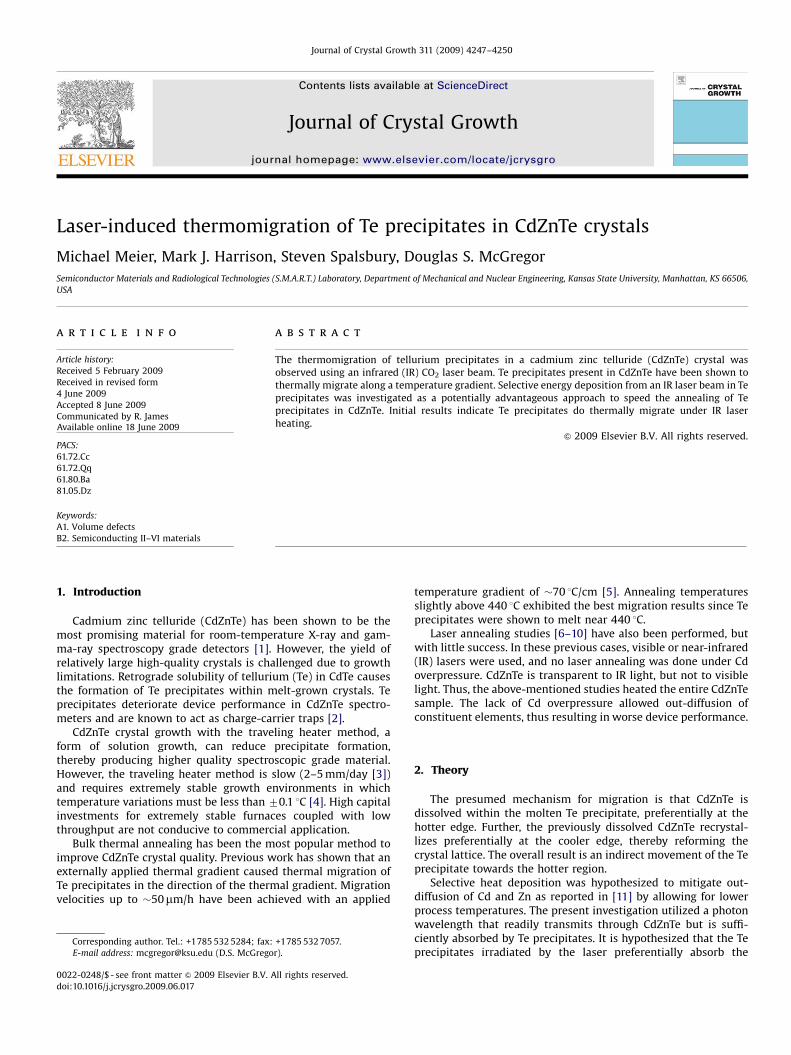
Fig. 2. Laser conditioner arrangement showing the beam expander and the
superimposing alignment laser. The laser was aligned to impinge on the CdZnTe
sample inside a furnace tube.
M. Meier et al. / Journal of Crystal Growth 311 (2009) 4247–42504248
energy on the laser impinging side, which imposes a temperaturegradient across the precipitate.
A coherent CO2 laser was used, providing a 1.8 mm + laserbeam with a power output up to 63 W. The CdZnTe crystal has abandgap energy ranging from 1.4 to 1.6 eV, and is transparent tothe IR CO2 laser emission with a wavelength of 10.6mm (andcorresponding photon energy of 0.1169 eV). Pure Te, with abandgap energy of 0.33 eV, might be expected to be virtuallytransparent to the CO2 laser as the photons are not energeticenough to raise electrons across the bandgap. However, stronginterband absorption caused by holes creates an absorption peaknear 11mm [12]. At 190 1C, the absorption coefficient is �100 cm�1
at 10.6mm and increases with temperature. This fact supportsobserved experimental results which clearly indicate that trans-mission of IR light at 10.6mm is strongly correlated to Teprecipitate density [13].
Numerical simulations modeling the laser energy uniformlyabsorbed at the surface of the Te precipitate were performed. Afinite difference code was written to compute the temperaturedistribution as a function of the radial position and time.Symmetry boundary conditions were applied at the center ofthe precipitate and adiabatic conditions halfway in betweenneighboring precipitates (�300mm) were assumed.
The computed temperature distribution strongly depends onthe size of the precipitate and the size and the power of the laserbeam. The results clearly indicate that laser pulses lead tosignificant local heating. The irradiation of a typical 40mmdiameter precipitate with the bare (unexpanded) laser over 2 msresults in a temperature difference between a Te precipitate andthe crystal material (CdZnTe) of approximately 80 1C (as shown inFig. 1). If the pulse is lengthened, or continued, the surroundingmaterial temperature rises, which can result in melting the
Fig. 1. Numerical simulation of radial temperature
crystal. It was observed that a 5�5�10 mm3 crystal orientedsideways to the 50 W beam indeed melted through after 5 min ofcontinuous exposure. Furthermore, the numerical simulationssuggest that time constants on the order of 5 ms are needed tosufficiently cool the sample after the laser pulse to preventmelting (see Fig. 1).
Intermittent laser power was therefore chosen for the opera-tion, thereby allowing for local cooling in order to prevent thecrystal from melting during the process. By choosing relativelyshort pulses (520 ms) the crystal bulk temperature is essentiallymaintained by the external thermal environment (furnace) andcan be independently controlled. About 60 Hz was chosen as thepulse frequency, thereby allowing for sufficient time (�15 ms) tolocally cool down the crystal.
profile in the vicinity of a 40mm precipitate.
ARTICLE IN PRESS
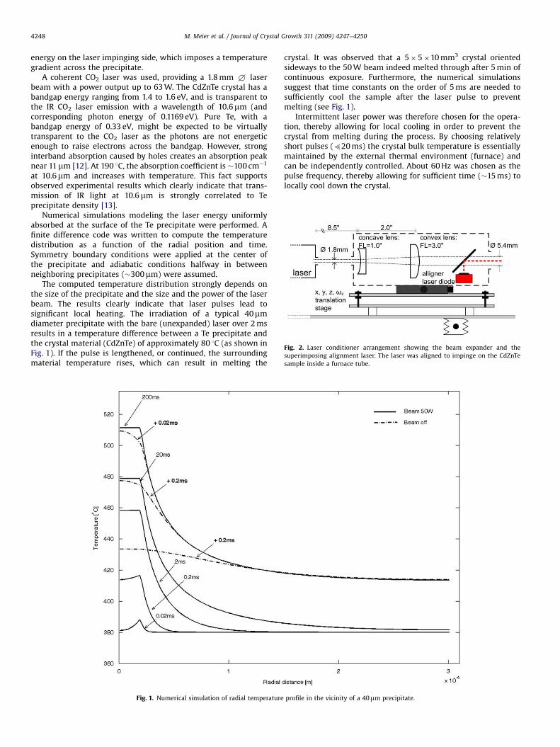
Fig. 3. IR microscope photographs of the investigated CdZnTe crystal before (upper) and after (lower) pulsed laser irradiation. Irradiation was performed on the left side of
the device for a period of 100 h. The distance between the two vertical lines is 1 mm.
M. Meier et al. / Journal of Crystal Growth 311 (2009) 4247–4250 4249
3. Experimental procedure
The coherent LC-50 D600 CO2 laser with a wavelength of10.6mm, a beam size of 1.8 70.2 mm in diameter and a maximumpower of 63 W was aligned to a laser conditioner arrangement as
shown in Fig. 2. The laser conditioner module consisted of tworail-mounted lenses, a visible diode pointer laser and a combinerlens. The laser beam first passed through a collimator lens (0.6 indiameter, (�)1.0 in focal length) to expand the beam. The secondcollimator lens (0.75 in diameter, (+)3.0 in focal length) was
ARTICLE IN PRESS
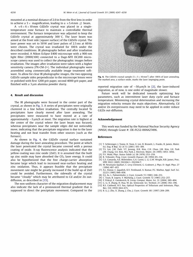
Fig. 4. The CdZnTe crystal sample (5�5�10 mm3) after 100 h of laser annealing.
The marked area, a surface oxide, marks the laser impinging point.
M. Meier et al. / Journal of Crystal Growth 311 (2009) 4247–42504250
mounted at a nominal distance of 2.0 in from the first lens in orderto achieve a 3� magnification, leading to a E5.4 mm + beam.
A E6� 6�10 mm CdZnTe crystal was placed in a single-temperature zone furnace to maintain a controllable thermalenvironment. The furnace temperature was adjusted to keep theCdZnTe crystal at approximately 300 1C. The laser beam wasaimed at the front side (square surface) of the CdZnTe crystal. Thelaser power was set to 50 W and laser pulses of 2.5 ms at 60 Hzwere chosen. The crystal was irradiated for 100 h under thedescribed conditions. IR photographs before and after irradiationwere recorded. A Nikon Eclipse E400 microscope with a 900-nmlight filter (D900/100) connected to a Dage-MTI DC200 micro-scope camera was used to collect the photographic images beforeirradiation. The images after irradiation were taken with a highersensitivity camera (PX-CM-2+). The individual photographs wereassembled using commercially available image treatment soft-ware. To allow for clear IR photographic images, the two opposingCdZnTe sample sides perpendicular to the microscope lenses werere-polished with first 1200 grit paper, second 4000 grit paper, andfinished with a 3mm alumina powder slurry.
4. Result and discussion
The IR photographs were focused in the center part of thecrystal, as shown in Fig. 3. A series of precipitates were originallyclustered in a line before irradiation. The centrally located Teprecipitates have clearly moved after laser annealing. Theprecipitates were measured to have moved at a rate ofapproximately �3mm/h at most. The migration rate is highest atthe center of the crystal where the laser beam was focused,whereas precipitates near the sample edges did not noticeablymove, indicating that the precipitate migration is due to the laserheating and not heat transfer from other sources (such as thefurnace).
As shown in Fig. 4, the CdZnTe crystal surface sustaineddamage during the laser annealing procedure. The point at whichthe laser penetrated the crystal became covered with a porouscoating of oxide. X-ray fluorescence analysis indicated that theyellow coating was zinc oxide (ZnO). It is assumed that the builtup zinc oxide may have absorbed the CO2 laser energy. It couldalso be hypothesized that the free charge-carrier absorptionbecame large which lead to increased near-surface heating andzinc oxidation. Thus, it appears feasible that the precipitatemovement rate might be greatly increased if the build up of ZnOcould be avoided. Furthermore, the sidewalls of the crystalbecame ‘‘cloudy’’ which may be attributed to Cd and/or Zn out-diffusion, as described in [13].
The non-uniform character of the migration displacement mayalso indicate the lack of a pronounced thermal gradient that issupposed to direct the precipitate movement. Compared to the
reported migration rate of �50mm/h in [2], the laser-inducedmigration, as of now, is one order of magnitude slower.
Future work will be dedicated towards optimizing keyparameters, such as intermittent laser duty cycle and furnacetemperature. Minimizing crystal deterioration and increasing themigration velocity remain the main objectives. Alternatively, Cdand/or Zn overpressures may need to be applied in order reduceCd/Zn out-diffusion.
Acknowledgement
This work was funded by the National Nuclear Security Agency(NNSA) through Grant #: DE-FG52-06NA27496.
References
[1] T. Schlesinger, J. Toney, H. Yoon, E. Lee, B. Brunett, L. Franks, R. James, Mater.Sci. Eng. R Rep. 32 (4–5) (2001) 103–189.
[2] T.S. Lee, J.W. Park, Y.T. Jeoung, H.K. Kim, C.H. Chun, J.M. Kim, I.H. ParkJ.M. Chang, S.U. Kim, M.J. Park, J. Electron. Mater. 24 (1995) 1053–1056.
[3] F.V. Wald, Phys. Status Solidi (a) 38 (1976) 253–259.[4] R. Triboulet, Prog. Cryst. Growth Charact. 28 (1994) 85–114.[5] G.S. Camarda, A.E. Bolotnikov, G.A. Carini, L. Li, G.W. Wright, R.B. James, Proc.
SPIE 5922 (2005) 592204:1–592204:7.[6] M. Neumann-Spallart, C. Levy-Clement, G. Grabnert, J. Phys. D: Appl. Phys. 27
(1994) 407–413.[7] A.L. Dawar, C. Jagadish, K.V. Ferdinand, A. Kumar, P.C. Mathur, Appl. Surf. Sci.
22/23 (1985) 846–858.[8] D.J. As, L. Palmetshofer, J. Cryst. Growth 72 (1985) 246–251.[9] C. Uzan, R. Legros, Y. Marfaing, J. Cryst. Growth 72 (1985) 252–257.
[10] P. Prikryl, E. Gatskevich, R. Cerny, Comput. Mater. Sci. 31 (2004) 389–404.[11] G. Li, X. Zhang, H. Hua, W. Jie, Semicond. Sci. Technol. 21 (2006) 392–396.[12] R.S. Caldwell, H.Y. Fan, Optical Properties of Tellurium and Selenium, Phys.
Rev. 114 (1959) 664–675.[13] B. Li, J. Zhu, X. Zhang, J. Chu, J. Cryst. Growth 181 (1997) 204–209.