Embed Size (px)
Citation preview

Laser Interferometer Space Antenna (LISA)
A Response to the Astro2010 RFI for the Particle Astrophysics and Gravitation Panel
Lead AuthorRobin Stebbins, Goddard Space Flight Center
[email protected], +1 (301) 286-3642
For the NASA/ESA LISA Project TeamMansoor Ahmed, Goddard Space Flight Center
Peter Bender, University of ColoradoCurt Cutler, Jet Propulsion Laboratory
Karsten Danzmann, U. of Hannover/AEI/MPIRoger Diehl, Jet Propulsion Laboratory
Stephen DePalo, Goddard Space Flight CenterAlberto Gianolio, European Space Research and Technology CenterOliver Jennrich, European Space Research and Technology Center
William Klipstein, Jet Propulsion LaboratoryJeffrey Livas, Goddard Space Flight Center
Paul McNamara, European Space Research and Technology CenterStephen Merkowitz, Goddard Space Flight Center
Moshe Pniel, Jet Propulsion LaboratoryThomas Prince, California Institute of Technology
Marcello Sallusti, European Space Research and Technology CenterMichele Vallisneri, Jet Propulsion Laboratory
Stefano Vitale, U. of TrentoJohn Ziemer, Jet Propulsion Laboratory

i
Laser Interferometer Space Antenna (LISA)
SUMMARYGravity dominates the Universe. Gravitational
waves are messengers, not from the radiant baryons of stars or gas or dust, but rather from the extreme interactions of compact dark objects, such as black holes of all sizes. They bring detailed information about violent events central to the origin and evo-lution of galaxies and stars. Though only indirectly observed as yet, gravitational waves will very likely be directly detected in the next decade, opening a whole new spectrum. The millihertz region of that spectrum is expected to have the largest number, the greatest variety and the strongest sources; that rich trove of astrophysical information is only ac-cessible from a space-based detector.
The Laser Interferometer Space Antenna (LISA) is an ESA-NASA project to develop and operate a space-based gravitational wave detector sensitive at frequencies between 3 ×10⁻⁵ and 0.1 Hz. LISA detects gravitational-wave induced strains in space-time by measuring changes of the separation between fiducial masses in three spacecraft 5 million kilometers apart.
LISA will discover many extraordinary astro-physical sources: tens to hundreds of inspiraling and merging massive black hole binaries out to a redshift of z ~20; tens of stellar-mass compact ob-jects spiraling into central massive black holes out to z ~1; more than ten thousand close, compact bi-naries in the Galaxy; a sky map of the background made by millions more; and possibly backgrounds of cosmological origins. The all-sky instrument will see thousands of sources in the first few months of operation. Astrophysical parameters, such as mass, spin and luminosity distance, of many sources will be measured with uncommon precision.
LISA will track more energetic inspirals for weeks to months, predicting progressively more accurate sky position and luminosity distance of the merger for electromagnetic observers. Owing to the revolu-tionary nature of gravitational wave detection, the numbers and types of LISA sources are somewhat uncertain. Fortunately, there are guaranteed sourc-es, close white dwarf binaries known from electro-magnetic observations, and many others that LISA should see in large numbers unless the Universe is radically different than electromagnetic observa-tions have led us to believe. By virtue of opening a new spectrum, gravitational wave astronomy prom-ises once-in-human-history discovery potential.
Gravitational wave observations will enable stud-ies of: the formation and growth of massive black holes and their co-evolving host galaxies; structure formation; stellar populations and dynamics in ga-lactic nuclei; compact stars; the structure of our Galaxy; General Relativity in extreme conditions;
cosmology; and searches for new physics. As out-lined in Key Science Goals, information from LISA sources will provide unique insight into extraordi-nary astrophysical objects. Combined with electro-magnetic observations, these insights will advance the broader scientific understanding.
The LISA mission architecture described in the Technical Overview has been stable since 1997 and under continuous development and analysis for more than two decades. The architecture is well de-fined and extensively analyzed. The requirements have been flowed down, and the error budget is well understood and laboratory tested.
The LISA concept relies on laser metrology and “drag-free” flight. Laser metrology is well established in the laboratory. Drag-free flight is an established space technology, but LISA requires better perfor-mance. LISA Pathfinder is a technology demonstra-tion mission for LISA, led by ESA, scheduled for launch in 2011. LISA Pathfinder will test a proof mass and supporting subsystems designed for LISA, drag-free control, microthrusters and interferom-etry technology for LISA. The Pathfinder ground development program is complete; engineering models of the science instruments have been built and flight qualified. Flight hardware is now under construction. Much of the LISA technology risk has already been retired by the development of LISA Pathfinder. The results from Pathfinder will be known while LISA is still in Phase A. Technology Drivers demonstrates how technical risk is being re-tired both through Pathfinder and a ground-based technology development program.
As outlined in Organization, Partnerships and Current Status, the LISA partnership is an effective international team based on long established agree-ments. The Project is in Formulation at both ESA and NASA, and ESA has had a formulation study contractor, Astrium GmbH, for four years. The Project team and independent organizations have estimated the mission cost and schedule multiple times since 2001, and the current estimates are ro-bust and reliable for the current state of develop-ment (see Schedule and Cost Estimates). LISA could be ready for a 2020 launch readiness date.
Further information can be found in the sci-ence white papers and project documents describ-ing LISA science, the mission concept, major mission elements, status of the technology and LISA Pathfinder. These documents are referenced in the sections that follow and are available from lisa.gsfc.nasa.gov/documentation.html. Many com-mon questions about the revolutionary nature and novel methods of LISA are answered in the FAQs at the same URL.

1–1
Laser Interferometer Space Antenna (LISA)
1. KEY SCIENCE GOALSOver the next two decades, gravitational-wave
(GW) astronomy is poised to make revolutionary contributions to our understanding of the uni-verse. The first GW detections are likely to come from advanced ground-based interferometers, which operate in the high-frequency band (10 to 103 Hz) and search for systems of stellar mass. By contrast, LISA will open up the low-frequency GW spectrum (3×10⁻⁵ Hz to 0.1 Hz). This band is rich in guaranteed sources such as the millions of compact binaries in our Galaxy; furthermore, it provides access to loud, long-lived GW signals, such as those emitted by coalescing massive black holes, allowing the determination of astrophysical parameters with extraordinary accuracy, and en-abling stringent constraints on the strong-field re-gime of general relativity .1,3 The Astro2010 white papers on low-frequency GW astronomy 3–6, 8–11 provide an excellent picture of this field’s excite-ment and broad promise.
In this section we summarize LISA’s key science goals, known as “LISA Science Objectives” by the LISA International Science Team and the LISA Project .1,2 For each of these objectives, the Sci-ence Team has defined several investigations and derived the corresponding observational require-ments. Below we briefly discuss each of the LISA science objectives and investigations. The Techni-cal Overview (Section 2) specifies the key LISA performance parameters that are required by the collective set of investigations, and that therefore enable the science objectives to be realized.
LISA Sources and SensitivityLISA will achieve its science objectives by detect-
ing and observing GW sources of different classes. Figure 1–1 shows the strength of a few represen-tative signals compared to the LISA instrument noise. Because LISA is an all-sky detector and most sources are long lived, their signals will be super-imposed in the LISA data set. The signals however are largely orthogonal, and can be extracted by cor-relating the LISA data with theoretical models of the expected waveforms. This process enhances the instantaneous signal-to-noise ratio (SNR) by the square root of the integration time, which can be over a year.
Not only will LISA detect thousands of sources with very high confidence, but it will also deter-mine their physical parameters, often with as-tounding accuracy. Roughly speaking, the masses of a binary system are encoded in the frequency evolution of the waveform; its sky location and orientation are encoded in the frequency and am-
plitude modulations imposed on the signal by LISA’s yearly revolution and rotation; all these parameters and the overall signal amplitude then determine the distance. For massive black-hole systems, black-hole spins can be extracted from their effects on frequency evolution and from the modulations of waveform polarization caused by the Lense-Thirring (spin-orbit) precession of the orbital plane.
LISA Science ObjectivesThe LISA International Science Team has ad-
opted a set of well-established science objectives. Their breadth indicates the wide diversity of sci-ence that LISA will address:1. Understand the formation of massive black
holes2. Trace the growth and merger history of mas-
sive black holes and their host galaxies3. Explore stellar populations and dynamics in
galactic nuclei4. Survey compact stellar-mass binaries and study
the structure of the Galaxy5. Perform new accurate tests of general relativity
LA002
veri�cationbinaries
(last 3 years)
(last 3 years)
(last 3 years)
LISA sensitivity to monochrom
atic sources(strain needed for SNR=
1 in 1 yr): log10 hLISA i
nstru
men
t nois
e: log
10 √
Sn [H
z–]
log10 f
–20
–19
–18
–17
–16
–24
–23
–22
–21
–20
–19
–5 –4 –3 –2 –1 0
–15
10 + 106 M EMRI at 3 Gpc
galacticbinaryforeground
106 + 106 M BH–BH at z=1
105 + 105 M BH–BH at z=1
Figure 1–1: The red curve shows LISA’s instrumental rms strain noise, in units of Hz–1/2 ; the blue curve represents confusion noise from unresolved Galactic binaries, which will dominate instrumental noise between 10–4 and 2×10⁻³ Hz. . The vertical axis on the right of the figure shows the corresponding LISA sensitivity to monochromatic signals (i.e., the GW strain needed to accumulate a matched-filtering SNR of 1 over a year of observation, for a single LISA Michelson interferometer). The small squares represent the frequencies and strengths of known Galactic binaries (LISA’s “verification binaries”); the two black curves and the green curve represent sources (two MBH binaries, and an EMRI, respectively) whose frequency evolves upward significantly during LISA’s observation. Roughly speaking, LISA can detect all sources above the noise curve, and their height above it approximates their SNR. See 1,2 for more details.

1–2
Laser Interferometer Space Antenna (LISA)
Table 1–1: A summary of LISA’s sources: their characteristics, estimated amplitudes and rates, parameter extraction accuracy, and science pay-offs.
6. Probe new physics and cosmology with gravi-tational waves
7. Search for unforeseen sources of gravitational waves
See 1,2,3 for details. These objectives and the cor-responding observational investigations drive the
formal LISA Science Requirements 2, which in turn are the basis for defining the instrumental performance parameters. We briefly discuss the investigations (and the required performance) in the following subsections. Table 1–1 provides a summary of GW sources and their science payoffs.
Sources for Low-Frequency GW Astronomy (3 × 10⁻⁵–0.1 Hz)Massive Black Hole (MBH) Merger
Characteristics Inspiral and merger of MBH binary (z = 0–20); Mass Range: 104–107 MuOrbital Period: 102–105 s; Signal Duration: ~ weeks to years
Detection Rate ~1/yr at z < 2; ~30/yr at z .15; SNRs up to several thousand
Observables Masses: ΔM/M .1%; Spins: ΔS/S .2% (typical detections)Luminosity Distance: ΔDL/DL ~ 5–20% (typical detections); ΔDL/DL . 3% (z = 1, limited by weak lensing)
Science Payoffs • Nature of seed BHs at z ~10–20; history of MBH growth and galaxy mergers • Tests of General Relativity in strong-field, highly dynamical regime
Capture of Stellar Mass Compact Objects by MBH
CharacteristicsCompact-object (BH, NS, or WD) inspirals into massive BH MBH Mass: 104 − 107 Mu ; orbital period: 102–103 s; signal duration: ~ years
Detection Rate ~50/yr, mostly captures of ~ 10Mu BHs at z ~ 1; Captured IMBHs detected to z /10
Observables Masses: ΔM/M . 0.1%; Spins: ΔS/S . 0.1% (typical detections)Luminosity Distance: ΔDL/DL . 4% (typical detections)
Science Payoffs• MBH spins reflect their growth history: high spins (a/M~ 0.9) arise from disk accretion; low spins from mergers of many smaller BHs • Populations and dynamics of compact objects in galactic nuclei • Precision tests of General Relativity and Kerr nature of MBHs
Ultra-Compact Binaries
Characteristics Primarily compact WD-WD binaries, mass transferring or detached; orbital periods: ~ 102 − 104 s
Detections ~ 20, 000 individual sources, including ≈ 10 known ”verification binaries”; Diffuse galactic background at f . 2mHz
Observables Orbital frequency; sky location to few degrees; chirp mass and distance from df/dt for some high-f binaries
Science Payoffs
• ~ 100–fold increase in census of short-period Galactic compact binaries • Evolutionary pathways (e.g., outcome of common envelope evolution) • Physics of tidal interactions and mass transfer • WD-WD binaries as possible SN Ia progenitors
Early Universe Stochastic Backgrounds
Possible Sources Early Universe 1st-order phase transition at kT~1 TeV (e.g., electro-weak transition); brane oscillations in large extra dimensions; cosmic (super-)strings
Observables Any early-universe background with Ωgw /10−10 will be detectable over foreground from galactic WD–WDs
Science Payoffs • Amplitude and spectral shape of Ωgw(f); early universe physics
Cosmic (Super-)String Bursts
CharacteristicsString loops generically develop “cusps” once per oscillation; these produce highly beamed GW bursts with universal profile: h(t) % |t − tc|1/3
Observables Sky positions, amplitudes, overall rate
Science Payoffs • Possible experimental proof of string theory; if string bursts observable, then generally so is string background: together strongly constrain string phenomenology

1–3
Laser Interferometer Space Antenna (LISA)
LA032
1. Understand the formation of massive black holes
Understanding MBH formation requires iden-tification of lower-mass BH “seeds” from which the MBHs evolved via accretion and successive mergers. The LISA design (e.g., its arm length) was chosen to provide good sensitivity for low-er-mass (~104–105 Mu) MBH mergers out to high redshift (z > 10) 1,4, LISA will measure their masses and spins to ~1% accuracy. LISA is sen-sitive also to the captures of intermediate mass BHs (IMBHs, ~102–103 Mu) by MBHs out to high redshifts.5 IMBHs are very interesting but still speculative objects; LISA can prove their ex-istence unambiguously, through highly precise determinations of masses.
2. Trace the growth and merger history of mas-sive black holes and their host galaxies
Just as facilities such as JWST and ALMA will study the evolution and growth of galaxies out to high redshift, LISA will undertake the comple-mentary study of MBH evolution and growth back to very early times, even before the epoch of re-ionization1,4. LISA will measure the masses, spins, distances, and rates of MBHs undergoing inspiral and merger, and thus answer several ques-tions. Did the MBHs at the centers of galaxies today begin their lives as ~100 – 1000 Mu objects, or as ~104 – 105 Mu MHs? Did the MBHs that
today have masses of 106 Mu grow primarily by gas accretion, or by mergers with other MBHs? LISA’s ability to measure MBH spins will be cru-cial, since growth from disk accretion leads to high spins, while growth by mergers leads to low-to-moderate spins, depending on the number of mergers and their mass ratios.
For the most energetic events, merger times and sky locations will be determined from the in-spiral GWs well in advance of the actual merger, allowing for simultaneous targeted searches for EM counterparts. In addition, the observation of captures of stellar-mass objects by MBHs (the so-called “extreme mass ratio inspirals,” or EMRIs) will provide precise masses and spins for nuclear MBHs out to z ~1. LISA’s sensitivity down to a frequency of ~3 ×10⁻⁵ Hz will provide the abil-ity to observe MBHs with masses up to 107 Mu, while its excellent sensitivity at a few mHz will allow precision measurements with EMRIs.1,5,9
3. Explore stellar populations and dynamics in galactic nuclei
LISA will observe EMRI events with a best-es-timate rate of tens to hundreds per year. Most of these will be stellar-mass BH captures, but LISA expects to see also neutron star and white dwarf
Investigations:•Search for a population of seed BHs at early
epochs •Search for remnants of the first (Pop III)
stars through observation of intermediate mass black hole (IMBH) captures, both at formation and at later epochs
Investigations:•Determine the relative importance of differ-
ent MBH growth mechanisms as a function of redshift
•Determine the merger history of 104 to 3×10⁵ Mu MBHs before the era of the earli-est known quasars (z ~ 6)
•Determine the merger history of 3×10⁵ to 107 Mu MBH at later epochs (z < 6)
•Determine the masses and spins of low-red-shift MBHs using observations of extreme mass ratio inspiral events (z ~ 1 or less)
•Enable the search for EM counterparts to MBH mergers to determine their host galaxies
Figure 1–2: Numerical simulation of binary black-hole inspiral and merger. Used with permission of Caltech/Cornell Numerical Relativity Group.
Investigations:•Characterize the immediate environment of
MBH in z < 1 galactic nuclei from EMRI capture signals
•Study intermediate mass black holes from their capture signals
• Improve our understanding of stars and gas in the vicinity of galactic black holes using coordinated GW and EM observations
1–4
Laser Interferometer Space Antenna (LISA)
captures.1,4,9 LISA will follow these capture events over ~105 highly relativistic orbits, measuring the spin and mass of the central MBH, the mass of the compact object (which is particularly interest-ing for determining the mass spectrum of stellar BHs), and the eccentricity of the orbit, all to a precision of ~0.01%. The luminosity distance will typically be determined to a few percent. The ca-pability to detect and study tens of EMRIs drives the LISA sensitivity requirement at frequencies of a few mHz.
4. Survey compact stellar-mass binaries and study the structure of the Galaxy
LISA will identify ~20,000 individual com-pact binaries in the Galaxy, and it will measure their orbital periods and sky distribution. (The Mock LISA Data Challenges have already given a demonstration of the global-fit algorithms that can do this.) Just as large pulsar surveys revealed separate classes of pulsars (e.g., recycled pul-sars and magnetars, in addition to the “vanilla” 1012-Gauss pulsars), we expect LISA’s large survey to uncover surprising new types of binaries and unexpected evolutionary pathways. The binaries with the shortest periods will provide insight into the physics of tidal interactions and mass trans-fer, and for some we will also get distances. In addition, at frequencies below 1 mHz, LISA will map the diffuse background from millions of un-resolved compact binaries in the Galaxy. See ref-erences1,6,7,9 for additional information.
5. Perform new accurate tests of general rela-tivity
LISA will test general relativity in several previ-ously impossible ways.1,8 First, LISA will use spe-cific compact binaries known from electromag-netic observations to measure GWs directly and confirm that their properties are consistent with the amplitude, orbital period, phase, and other characteristics determined from electromagnetic (EM) observations. Second, LISA will use EMRI observations to map the spacetime geometry of central galactic objects, testing precisely whether they are the Kerr black holes predicted by general relativity, or more exotic objects such as naked singularities or boson stars. Third, LISA will ob-serve the inspiral, merger, and ringdown of MBH mergers: because the strongest MBH signals will have SNRs in the thousands (two orders of mag-nitude higher than possible with ground-based GW detectors), and thanks to the recent break-throughs in numerical relativity, it will be pos-sible to compare LISA’s observations with highly accurate predictions of what the waveforms should look like according to general relativity, allowing very precise tests of the theory in the ultra-strong field regime.
6. Probe new physics and cosmology with gravi-tational waves
Investigations:•Detect gravitational waves directly and mea-
sure their properties precisely•Test whether the central massive objects in ga-
lactic nuclei are the BHs of general relativity•Make precision tests of dynamical strong-
field gravity in MBH binaries
Investigations:• Illuminate the formation and evolution of
Galactic stellar-mass binaries; constrain the diffuse extragalactic foreground
•Determine the spatial distribution of stellar mass binaries in the Milky Way and environs
• Improve our understanding of white dwarfs, their masses, and their interactions in bina-ries, and enable combined GW and EM ob-servations
LA031
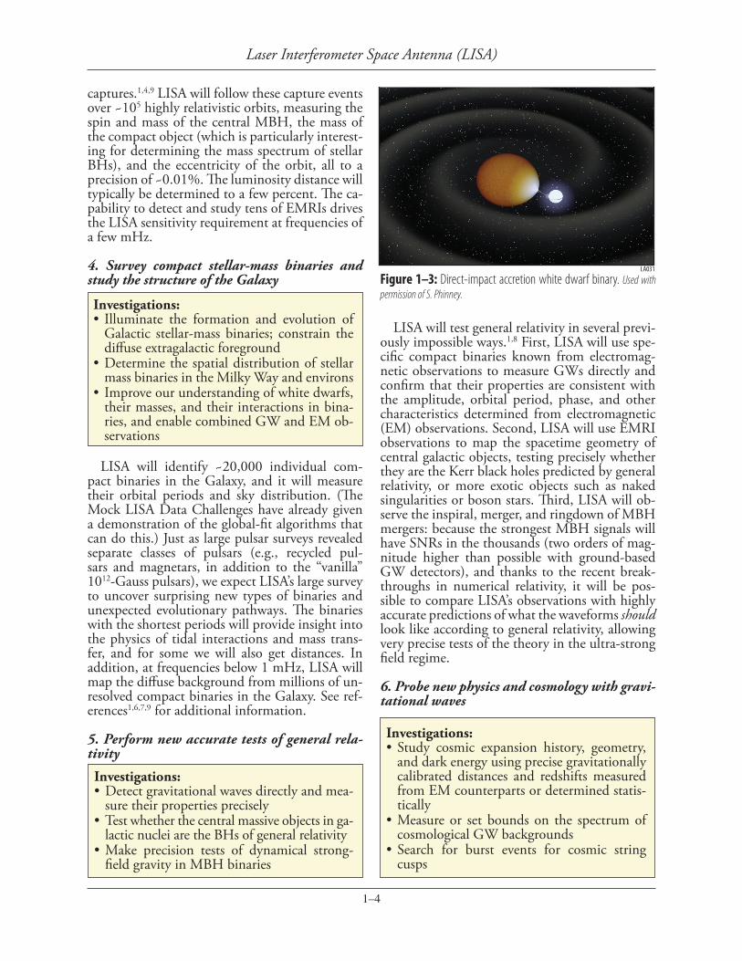
Figure 1–3: Direct-impact accretion white dwarf binary. Used with permission of S. Phinney.
Investigations:•Study cosmic expansion history, geometry,
and dark energy using precise gravitationally calibrated distances and redshifts measured from EM counterparts or determined statis-tically
•Measure or set bounds on the spectrum of cosmological GW backgrounds
•Search for burst events for cosmic string cusps

1–5
Laser Interferometer Space Antenna (LISA)
Because LISA is essentially self-calibrating, its measurements—like baryon acoustic oscillations, but unlike practically all other distance determi-nation methods in extragalactic astronomy—will provide precise, absolutely calibrated luminos-ity distances to both MBH mergers and EMRIs. Several mechanisms have been suggested that could lead to electromagnetic (EM) counter-parts to MBH mergers, allowing astronomers to determine the redshift of the host galaxy. Even a handful of such detections would constrain the Hubble constant H0 to ~1%, in a manner inde-pendent of conventional methods. The current uncertainty in the Hubble constant (~10% from the HST Key Project) actually dominates the cur-rent uncertainty in Ωk , the fraction of the closure density due to the spatial curvature of the uni-verse. And even without EM counterparts, a sta-tistical analysis of all EMRI detections, combined with redshifts of all galaxies in the LISA error box (as obtained from EM surveys) could also provide an accurate, independent measurement of H0 .
1,10
In addition, LISA has unique abilities to detect and quantify a remnant isotropic GW background from the early universe. It will be especially sensi-tive to GWs from phase transitions at the TeV scale. This includes the electro-weak phase tran-sition and (more speculatively) phase transitions associated with brane dynamics in large extra di-mensions.1,11 LISA will also be highly sensitive to GWs from cosmic (super-)strings: it may observe both a stochastic background from their large-scale oscillations, and individual highly beamed GW bursts from the cusps that have been shown to develop generically on the strings.1,11 Indeed, LISA could provide experimental verification of string theory.
7. Search for unforeseen sources of gravitation-al waves
LISA has tremendous discovery potential. It covers four decades of the GW frequency spec-trum with high sensitivity, and it is capable of detecting individual sources out to very high red-shift (z > 15). The history of astronomy strongly suggests that opening such a wide and qualitative-ly new observational window should yield very significant surprises, revealing new objects and phenomena that will otherwise remain invisible to us.3
References1 LISA Science Case: T. Prince et al., Probing the
Universe with Gravitational Waves, located at http://www.srl.caltech.edu/lisa/mission_documents.html
2 LISA Science Requirements Document, located at http://www.srl.caltech.edu/lisa/mission_documents.html
3 T. Prince, “The Promise of Low-Frequency Gravitational Wave Astronomy”, Astro2010 WP (2009)
4 P. Madau et al., “Massive BH Across Cosmic Time”, Astro2010 WP (2009)
5 C. Miller et al., “Probing Stellar Dynamics in Galactic Nuclei”, Astro2010 WP (2009)
6 G. Nelemans et al., “The Astrophysics of Ultra-Compact Binaries”, Astro2010 WP (2009)
7 G. Nelemans, arXiv:0901.1778 (2008)8 B. Schutz et al., “Will Einstein Have the Last
Word on Gravity?”, Astro2010 WP (2009)9 S. Phinney, “Finding and Using Electromag-
netic Counterparts of Gravitational Wave Sources”, Astro2010 WP (2009)
10 C. Hogan et al., “Precision Cosmology with Gravitational Waves”, Astro2010 WP (2009)
11 C. Hogan and P. Binetruy, “GW from New Physics in the Early Universe”, Astro2010 WP (2009)
(WP = white paper)

2–1
Laser Interferometer Space Antenna (LISA)
2. TECHNICAL OVERVIEW
Measurement Concept and Performance Requirements
Gravitational waves are a time-varying strain in space-time. A passing gravitational wave can be detected by measuring the changing separa-tion between reference objects, called “proof masses.” These measurement fiducials must be isolated from forces causing motions that could be confused with those caused by the gravita-tional waves. The LISA concept uses continuous laser ranging of a 5-million kilometer separation between free-falling proof masses in very low-dis-turbance environments. This ranging is an optical analog of conventional radar ranging.
The sources anticipated in the LISA frequency band require strain sensitivity* as low as 10-20/√Hz. That strain sensitivity is achieved by interferomet-ric readout to ~10-5 cycles/√Hz of 1 µm light over a 5×10⁹ m arm length. Most of the signals can be coherently integrated for months to years. The performance of the Interferometry Measurement System (IMS) is characterized by its displacement sensitivity.
Disturbances are kept low by a benign space environment, “drag-free” operation and careful design of payload and spacecraft. A “drag-free” satellite has a free-falling proof mass enclosed by the satellite that senses and follows the proof mass. This technology, pioneered in 1972 by the TRIAD mission, reduces the time-varying forces on the proof masses from the external environ-ment and the surrounding equipment. The per-formance of the Disturbance Reduction System (DRS) is characterized by its residual acceleration.
The performance of LISA is largely described by the strain noise curve in Figure 1–1. That curve depends on the following performance pa-rameters (defined from 3 × 10⁻⁵ to 0.1 Hz): 1 • The one-way displacement noise of the IMS is
1.8 × 10⁻¹¹ m/√Hz.• The DRS residual acceleration noise on a single
proof mass is 3.0 × 10⁻¹⁵ m/s2/√Hz.• The three arm lengths are 5 million kilometers.
The 5-year operational lifetime sets the maxi-mum length of integration for periodic signals and the number of sources for mergers.
The Science InstrumentationThe constellation of the three “sciencecraft”
(i.e., tightly integrated payload and spacecraft bus), each housing two proof masses and trans-mit/receive terminals for two interferometer arms, constitutes the science instrument. The triangular formation is established by placing the sciencecraft in specially chosen heliocentric orbits (see Figure 2–1) and sustained by natural orbital evolution, i.e., without orbital maintenance. The plane of the triangle is inclined 60° to the ecliptic, the sides are 5 × 10⁶ km, and the center follows the Earth in its orbit, ~20° behind.
The Interferometry Measurement System mon-itors changes in the separation between proof masses through three measurements: two ‘short’ interferometers measure changes between the proof masses and their respective sciencecraft at either end of the path, and a ‘long’ interferom-eter measures changes in the separation between the sciencecraft. The six short interferometers are conventional heterodyne metrology interferom-eters. In the long interferometers, the laser at one end transponds the received laser phase back to the originating sciencecraft, with a programmable frequency offset, where it is beat against the local laser. The phases of the two lasers on each science-
LA019
Earth
20°
1 AUSun
60°
5 x 10⁹ m
Sun
LA020
Figure 2–1: The three LISA sciencecraft orbit in an equilateral triangle. The grey line shows the orbit of the Earth. The blue circle on the right shows the orbit of one sciencecraft. There is no active control of the formation; no orbital maintenance is needed.
*Amplitude spectral densities, i.e., the square root of the power spectral density, are commonly used to characterize performance-related quantities, because gravitational wave detectors measure amplitude, not power.
2–2
Laser Interferometer Space Antenna (LISA)
craft are also compared through a “back link” fiber connecting the two optical benches serving the two measured paths at that sciencecraft. With the transponder architecture and the back-link phase comparison, five of the lasers can be phase-locked to the sixth master laser.
The laser beat signals are digitized by a high sensitivity phasemeter. Laser frequency noise is a major consideration since the natural noise of the most suitable laser exceeds the gravitational wave signal by many orders of magnitude. Fre-quency noise is reduced by three methods: pre-stabilization of the laser to a reference cavity, ac-tive stabilization to a combination of the long arms (the science signal is in the difference of two arms), and Time Delay Interferometry (TDI), an algorithm applied in data analysis that effectively achieves the frequency noise cancellation in a manner analogous to the “white-light fringe” in a Michelson interferometer by combining signals from two arms after time-shifting to account for differences in arm length. TDI is more fully ex-plained in LISA Data Analysis Status.2 Laboratory tests have shown that the three methods together can reduce the laser frequency noise far beyond what is needed.
The laser subsystem consists of a 40 mW Nd:YAG non-planar-ring master oscillator oper-ating at 1064 nm and a 2 W Yb fiber amplifier. It is fully redundant, fiber-coupled and has a fiber-based electro-optic phase modulator for apply-ing sideband signals to the science beam. Data, ranging and clock signals are transmitted between sciencecraft on the sidebands. Similar laser sub-systems have been operating on the TerraSAR-X and NFIRE missions since 2007.
The laser frequency is pre-stabilized with a reference cavity made of an ultra-low expan-
sion glass in a very quiet thermal environment. A high-bandwidth phase-locking signal is de-rived from the phasemeter. The TDI algorithm requires knowledge of the arm lengths obtained with a ranging signal imposed on the long-arm interferometer and extracted by the phasemeter.
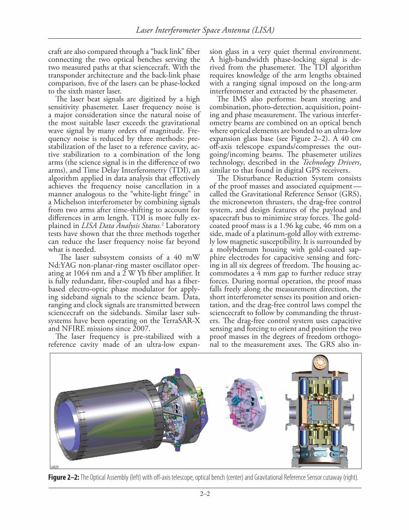
The IMS also performs: beam steering and combination, photo-detection, acquisition, point-ing and phase measurement. The various interfer-ometry beams are combined on an optical bench where optical elements are bonded to an ultra-low expansion glass base (see Figure 2–2). A 40 cm off-axis telescope expands/compresses the out-going/incoming beams. The phasemeter utilizes technology, described in the Technology Drivers, similar to that found in digital GPS receivers.
The Disturbance Reduction System consists of the proof masses and associated equipment — called the Gravitational Reference Sensor (GRS), the micronewton thrusters, the drag-free control system, and design features of the payload and spacecraft bus to minimize stray forces. The gold-coated proof mass is a 1.96 kg cube, 46 mm on a side, made of a platinum-gold alloy with extreme-ly low magnetic susceptibility. It is surrounded by a molybdenum housing with gold-coated sap-phire electrodes for capacitive sensing and forc-ing in all six degrees of freedom. The housing ac-commodates a 4 mm gap to further reduce stray forces. During normal operation, the proof mass falls freely along the measurement direction, the short interferometer senses its position and orien-tation, and the drag-free control laws compel the sciencecraft to follow by commanding the thrust-ers. The drag-free control system uses capacitive sensing and forcing to orient and position the two proof masses in the degrees of freedom orthogo-nal to the measurement axes. The GRS also in-
Figure 2–2: The Optical Assembly (left) with off-axis telescope, optical bench (center) and Gravitational Reference Sensor cutaway (right).LA029

2–3
Laser Interferometer Space Antenna (LISA)
cludes a caging subsystem for the proof mass, an active charge control subsystem using UV light to counter cosmic ray charging and a vacuum sub-system. The GRS for LISA, already developed for Pathfinder, is discussed further in the Technology Drivers section below.
The LISA Project is developing three differ-ent micronewton thruster technologies, based on the electro-spray of nano-droplets or metal ions. The micronewton thruster must provide the ~9 micronewton (µN) force per thruster to counter solar radiation pressure, the low thrust noise (<0.1 µN/√Hz), the 30 µN maximum thrust required for control after separation, and the proportional control needed for drag-free operation. Two thruster technologies will be flown on LISA Pathfinder. This technology is addressed in the Technology Drivers section.
The drag-free control system governs the orien-tation of the sciencecraft, its position relative to the two proof masses, the orientation of the two proof masses, the position of the proof masses relative to their housings in degrees of freedom orthogonal to their respective measurement di-rections, the articulation angle between the two telescopes and the point-ahead angle for both measurement arms. Modeling has shown that conventional control design is adequate for gener-ating the necessary commands for IMS and GRS actuators from on-board IMS and GRS sensors. The control system also supports initial pointing and laser frequency acquisition. LISA Pathfinder will test two versions of LISA-like drag-free con-trol systems. The success of Pathfinder will be evident early in its operational phase in time to inform LISA’s Phase A.
To keep residual disturbances on the proof masses low, some care must be taken in the de-sign of the payload and spacecraft bus. The cur-rent baseline achieves the desired thermal stabil-
ity through conventional passive design and the constant solar angle afforded by the orbits. The variation of the solar constant is the largest source of noise from the external environment; the varia-tion in solar heating from the orbital ellipticity is well out of the measurement band. The magnetic requirements can be satisfied with moderate mag-netic cleanliness. The gravitational attraction of the sciencecraft equipment can be mitigated by careful distribution of mass and by modest trim masses placed close to the proof masses.
More information on the topics in this section can be found in project documents describing the LISA mission concept,3 payload,4 and tech-nology status.5
Other Mission ElementsThe spacecraft bus, propulsion module, launch
vehicle and operations in the LISA mission con-cept are straightforward. The mission timeline calls for a single launch directly into an escape tra-jectory. The three identical sciencecraft, each with attached propulsion units, separate from each oth-er and proceed on cruise orbits to their different operational orbits. After a 14-month cruise phase, the three sciencecraft separate from their propul-sion modules and commence a 4-month commis-sioning phase. Science operations last 5 years in the baseline mission, extendable to 8.5 years.
The LISA spacecraft bus must be tightly inte-grated to the science instrumentation, but can be implemented with conventional heritage com-ponents. The bus has a simple cylindrical shape (see Figure 2–3), approximately 0.925 m high by 2.86 m in diameter. Masses are given in Table 2–1. The thermal design incorporates three stages of passive isolation that, with the constant 30° sun angle, results in an extraordinarily stable thermal environment in the GRS and on the optical bench. The power system will generate 1,300 W (BOL)
Figure 2–3: Sciencecraft (left) and propulsion module with integrated sciencecraft (right).
LA001
LA003

2–4
Laser Interferometer Space Antenna (LISA)
to serve an average science operations demand of 794 W and a short-term peak power demand of 1,103 W, with 30% contingency. The communi-cations system utilizes X-band and Ka-band with omni and high gain antennas. This system will support 90 kbps down to, and 2 kbps up from, 34 m DSN antennas. The micronewton thrusters described in the science instrumentation are the sole bus propulsion. The drag-free controller, also described above, provides attitude and position control during science operations. At other times, attitude control is accomplished with coarse sun sensors, fiber gyros, and two star trackers with 1 arcsec accuracy. A conventional Control and Data Handling system based on a Rad750 processor and a fault-detection-and-recovery controller can readily carry out normal spacecraft functions and collect science and housekeeping data at ~5 kbps.
The propulsion module is an expendable at-tachment to the sciencecraft that provides the 1,130 m/s ΔV needed during cruise phase. It is separated after the bus is inserted in its operation-al orbit. It only consists of structure, separation mechanisms, propellant tanks and a bi-prop pro-pulsion system. The load path of the launch stack is carried through an exterior cylinder that mates to the launch adaptor and/or another propulsion module in the launch stack.
The baseline LISA architecture requires a me-dium-lift EELV, capable of accommodating the three vehicle pairs (i.e., sciencecraft and propul-sion module) in its fairing, and of lifting the launch mass with a C3 (escape energy) of 0.5 km2/s2. The architecture is based on one of the launchers in the current fleet capable of this performance.
Normal LISA science operations require no re-pointing or formation maintenance maneuvers. DSN contact with a single sciencecraft, lasting 8 hours, occurs every second day. For a few days during particularly energetic massive black hole mergers, routine housekeeping interruptions must be kept to a minimum and more frequent downlinks are performed to support timely up-dates on predicted mergers to other astrophysical
observers. These are expected a few times per year. Laser beam pointing and frequency acquisition in the commissioning phase will require the most intense interaction with the sciencecraft. There will be a single U.S. operations center control-ling the mission and interacting with the DSN and science centers in both the U.S. and Europe where the data will be analyzed.
More information on the topics in this section can be found in project documents describing the LISA sciencecraft,6 propulsion module,7 opera-tions plan,8 and technical budgets.9
Robustness and RedundancyThe LISA mission concept relies on technolo-
gies that are either new to spaceflight or must perform to more demanding requirements than prior applications. It also relies on many subsys-tems operating successfully throughout the mis-sion lifetime. To retire technical risk early, ESA and NASA have committed to a dedicated dem-onstration flight, a rare event for a major mis-sion, that will mature the critical technologies to TRL 8 while LISA is still in Phase A. As a result of the ground development for Pathfinder, substan-tial technical risk has already been retired. Those technologies are already at TRL 5-6.
The baseline architecture is a conservative de-sign with a high level of redundancy. For example, the science requirements can be met with only 4 of 6 one-way measurement links operational; all error budgets have a 35% margin at the sys-tem level; the flight system is designed to have no credible single point of failure; there is full redun-dancy of the laser and microthruster subsystems.
Data AnalysisThe waveforms from gravitational wave sourc-
es contain a great deal of information about the sources, and, by observing thousands to hun-dreds of thousands of cycles, LISA can make pre-cision measurements of the source information. For example, from the waveform of the inspiral and merger of two comparable mass black holes, LISA can determine the masses, spin vectors, sky position, orientation, luminosity distance, and orbital parameters with the precision shown in Table 1–1. Although LISA is an all-sky detector, the source direction is encoded on the waveform as frequency modulation caused by the Doppler shift of the constellation’s motion about the Sun and as an amplitude modulation caused by the motion of the antenna’s sensitivity pattern across the sky. Figure 2–4 illustrates the richness of grav-itational wave signals and the strength of gravita-
Table 2–1: Top Level LISA Mass BudgetItem Contingency Allocation (kg)
Spacecraft bus (each) 30% 452
Science instrument per bus 30% 190
Propulsion module (each, dry) 30% 409
Propellant per vehicle (includes mass contingency)
527
Launch adapter 212
Launch mass 4,947

2–5
Laser Interferometer Space Antenna (LISA)
tional wave sources even at very high redshifts.LISA data analysis must separate many simul-
taneous sources and estimate the physical and astrophysical parameters of each. Initially, laser frequency noise must be removed by applying Time Delay Interferometry, which amounts to adding or subtracting time-shifted phasemeter outputs. The resulting data is naturally calibrat-ed by the well-known wavelength of the lasers. The characteristic parameters of most sources are estimated by matched filtering with a fam-ily of theoretical waveform templates that cover parameter space. The waveforms are very well known. The number of simultaneous sources and the template families can be quite large, but a major community effort, called the Mock LISA Data Challenges (MLDC) has already demon-strated that efficient global-fitting methods (e.g., Markov Chain Monte Carlo algorithms) are very effective. The MLDC simulates increasingly re-alistic data sets, distributes them to participating groups to analyze and then assesses the perfor-mance of the participants. The final product of the joint European/U.S. data analysis effort will be a catalog of gravitational wave sources and their parameters, as well as the underlying data,
satellite ephemerides, and software tools on which the source catalog is based.
More information on LISA data analysis can be found in LISA Data Analysis Status.2
References All references are available at:
http://lisa.gsfc.nasa.gov/documentation.html1 LISA International Science Team, LISA
Science Requirements Document, LISA-ScRD-004 (2007).
2 LISA Mission Science Office, LISA Data Analysis Status, LISA-MSO-TN-1001 (2009).
3 LISA Project, Laser Interferometer Space Antenna (LISA) Mission Concept, LISA-PRJ-RP-0001 (2009).
4 LISA Project, Payload Preliminary Design Description, LISA-MSE-DD-0001 (2009).
5 LISA Project, LISA Technology Status Sum-mary, LISA-MSE-RP-0001 (2009).
6 LISA Project, Sciencecraft Description, LI-SA-SC-DD-0001 (2009).
7 LISA Project, Propulsion Module Descrip-tion, LISA-SC-DD-0002 (2009).
8 LISA Project, LISA Operations Concept, LISA-OPS-RP-0001 (2009).
9 LISA Project, LISA System Technical Bud-gets, LISA-MSE-BR-0001 (2009).
h + D
/Gµ/
c2 ) 0.5
0
-0.5
Time (hours)0 2 4 6 8
LA035
10 12
Xs
8e-20
6e-20
4e-20
2e-20
0
-2e-20
-4e-20
-6e-20
-8e-20
t (s)0 2000 4000 6000
-1e+05 0 1e+05
Figure 2–4: Black hole inspiral waveforms. The segment on the top shows the the complex modulation of an EMRI waveform. The segment on the bottom shows the strength of the signal during merger from two 105 Mu spinless black holes at z = 15, with realistic instrument noise.

3–1
Laser Interferometer Space Antenna (LISA)
3. TECHNOLOGY DRIVERSGravitational Reference Sensor
The Gravitational Reference Sensor (GRS) is the heart of the LISA sciencecraft as it includes the proof mass: the inertial reference for the gravita-tional wave measurement. This system shares many common design features with precision space ac-celerometers (such as the GRACE accelerometer), but has a weaker coupling to the spacecraft, with gaps of many mm around the proof mass, no me-chanical contact, and very low sensing voltage. The proof mass position is sensed both capacitively and optically. The optical sensing forms the “short arm” (proof mass to local optical bench) of the gravi-tational wave measurement and is combined with the capacitive readout to drive the spacecraft drag free control. The primary challenge in the GRS development is verifying its performance when it cannot be fully operated on-ground.
Dedicated LISA GRS technology development began in 1998 and was accelerated in 2001 with ESA’s decision to fly LISA Pathfinder (LPF). The majority of recent GRS development is focused on building and testing the flight GRS for LPF. Al-though this effort focused on LPF, the GRS is designed to meet all of the LISA requirements.
Extensive laboratory testing of breadboards and engineering models of the GRS have dem-onstrated many of the LISA requirements. To account for unavoidable gravitational and sus-pension noise in ground testing, several novel test
setups were developed to verify the GRS perfor-mance. All the major contributors to the accelera-tion noise budget were validated and their levels verified through the laboratory testing that isolate each effect. In addition, torsion pendulum mea-surements of the LPF engineering model provide a limited system level performance verification, and puts an upper limit of 5 × 10-14 ms-2/√Hz at 1 mHz on unpredicted surface forces acting on the proof mass (the most feared disturbances as they are challenging to model). This system lev-el test is within a factor of 2 from LPF goal and within a factor of about 16 from LISA require-ments at the same frequency.
Engineering models of the GRS subsystems have successfully passed environmental testing for LPF. The system level qualification is currently underway. The LPF flight units are scheduled for delivery at the end of 2009. Although the required LPF measurement bandwidth only goes down to 1 mHz, testing will be performed down to 0.1 mHz. Additional low-frequency laboratory testing of the electronics remains to verify they meet the more stringent LISA requirements. These tests are straightforward, but time consuming.
The LPF development has already significantly reduced the risk of the GRS to the LISA mission by raising its TRL to between 5 and 6, a level sufficient to transition from technology develop-ment into implementation. The LPF mission will demonstrate the GRS performance in a flight en-vironment and validate the ground verification procedures. This demonstration will mitigate the risk that the noise models and test program have missed some critical performance limitation. After the flight demonstration, the GRS will be con-sidered very mature, having a TRL between 8-9.
LA011
LA012
Figure 3–1: Engineering models of the GRS subsystems have successfully passed LPF environmental testing.
Figure 3–2: Torsion pendulums are used to simulate the space environment when testing the GRS on-ground.

3–2
Laser Interferometer Space Antenna (LISA)
ment. Tests have demonstrated the performance of all primary functions of the phase measure-ment including laser frequency noise cancellation, clock noise transfer and correction, and weak-light phase locking. Absolute ranging and laser commu-nication will be added in 2009. An architecture study for the flight implementation of the DSP has raised that portion to TRL 5. Development of the entire PMS to TRL 6 is underway and planned to be completed in 2012.
Figure 3–4: The PMS has been demonstrated at TRL 4 in an interferometer testbed replicating the LISA signal environment (top). Digital tests of the DSP have demonstrated linearity 1000x better than required for LISA (bottom).
Figure 3–5: The TRL 4 quadrant photoreceivers have demonstrated the primary noise requirements over the 4-20 MHz signal bandwidth.
Phase Measurement SystemThe phase measurement system (PMS) provides
the “photons to bits” readout of the laser interfer-ometer signals containing the gravitational-wave strain information and providing displacement and angular readout used in the drag-free control system. By measuring with microcycle accuracy the phase of the heterodyne beatnote between la-sers with a wavelength of 1 micrometer the PMS provides picometer-level sensitivity to displace-ments between the LISA sciencecraft.
Only two component-level technologies require development: InGaAs quadrant photoreceivers with a 1 mm diameter active area and 13 pW/√Hz noise-equivalent-power over the signal frequency 4–20 MHz, and the digital signal processing that forms the heart of the phasemeter. LISA-specific challeng-es for the DSP portion include: microcycle/√Hz phase precision in the presence of large laser fre-quency fluctuations and a low SNR environment, the need to measure multiple heterodyne frequen-cies simultaneously, and tracking changing Doppler shift over the frequency range of 4–20 MHz. The DSP extends the digital phase-locked loop architec-ture and signal processing strategies of the Black-jack GPS receiver flying on the GRACE mission to the more stringent LISA requirements.
The remaining elements of the PMS are not viewed as technology items. These include: 8–bit analog-to-digital converters (ADCs) running at 50 Msamples/s; ultra-stable oscillators (USOs) with instabilities below 10-11 for averaging times of 30 seconds to act as the time reference for phaseme-ter sampling; and x-band frequency multipliers for modulating side tones onto the outgoing laser.
Following the LISA Technology Development Plan from 2005 the entire PMS has been demon-strated to TRL 4 and tested in an interferometer testbed that simulates the LISA signal environ-
LA030
10-2
Phase
Noise
[cycl
es/√H
z]
108
106
104
102
100
10-2
10-4
10-6
10-1 100 101
Frequency [Hz]
Injected noise
Prestabilized laser noise
Noise allocationResidual noise
Typical unstabilized laser noise
Demo
nstra
tedsu
ppres
sion
Requ
ired
supp
ressio
n
10010-110-2
Frequency [Hz]
Displa
cemen
t Nois
e [pm
/√Hz
]
1010
108
106
104
102
100
Test bed Goal
Test bed noise �oorTest bed requirement
USO NoiseNoise after USO correction
Raw Interferometer noise
Raw Laser Frequency Noise Contribution
Noise after TDI
LA013
Front end electronics
Photoreceivers
Digital Signal Processing(Phasemeter core)
Frequency Distribution
USO Multiplier
S/C
Laser
Modulator
ADCs FPGAs + Processor
Figure 3–3: Major components of the Phase Measurement System. The LISA Technology Development Plan (2005) describes the devel-opment plan for the photoreceivers and the digital signal processing core of the phasemeter, the only component technology items.
LA025
LA007
0 2015105
Freq [MHz]
NEP; lam = 1.06 µm, eta = 0.8
NEP [
pW/rt
hz]
15
10
5
0
MeasuredRequirement Max

3–3
Laser Interferometer Space Antenna (LISA)
over 50,000 hours of operation with multiple thruster units in multiple 3,000-hour class tests designed around the LPF mission duration (90 days). These wear-tests have helped to identify, develop, and verify comprehensive physics-based models of various failure modes and gradual wear mechanisms. None of the known lifetime limiting mechanisms precludes either of the LPF microthruster technologies from meeting the LISA lifetime requirement. Additional ac-celerated life tests are now underway to further characterize the life limiting mechanisms and to help identify and eliminate any remaining failure modes. It is important to note that for both sys-tems, the flight units will be designed with com-plete redundancy to insure a successful mission.
Figure 3–6: (Above left) Two flight CMNT clusters are ready for integration onto LPF.Figure 3–7: (Above right) The Slit-FEEP is currently completing its qualification program for LPF.
Figure 3–8: Both types of thrusters have demonstrated the LISA thrust-noise.
Micronewton ThrustersLISA requires micronewton thrusters to pro-
vide the fine spacecraft attitude and position control for drag free flight and beam pointing to the distant spacecrafts. The thrusters are operated continuously during science operations with their thrust levels set by the disturbance reduction sys-tem control loops. Of order 10 µN of thrust is re-quired to counteract the solar radiation pressure, the largest external force acting on the space-craft. The open loop thrust noise must be kept ≤0.1 µN/√Hz above 1 mHz and ≤10 µN/√Hz be-low 1 mHz in order to keep the spacecraft motion relative to the proof masses as small as possible. The largest remaining challenge for the micro-newton thruster technologies is demonstrating the LISA lifetime requirement.
Three different thruster technologies are cur-rently capable of meeting the LISA thrust and thrust noise requirements: colloid micronewton thruster (CMNT) made by Busek Co. in Bos-ton, cesium slit field emission electric propulsion (FEEP) made by ALTA S.p.A. in Italy, and indium needle FEEP thruster made by ARC Seibersdorf in Austria. These thrusters all belong to the cat-egory of field emission or electrospray propulsion.
The Busek CMNT recently achieved TRL 6 and will fly on LPF. The CMNT have demonstrated the required thrust noise and resolution through several direct and indirect thrust measurements. An EM-level CMNT system also passed through a 3400-hour life test successfully (sufficient for LISA Pathfinder). The Busek CMNT flight units have completed all integration and test (I&T) activities and are ready to ship to ESA for integration onto the LPF spacecraft in the summer of 2009.
ESA is completing the development on the two types of FEEP thrusters for a wide class of mis-sions that demand steady, high-resolution thrust. ESA recently selected the Slit-FEEP technol-ogy for flight on LPF. The qualification program and flight model manufacturing is now underway for the Slit-FEEP. Development of the Needle-FEEP technology will continue to completion maintaining the technology as a reliable backup for LPF and LISA. Similar to the CMNT, these thrusters have also demonstrated the required thrust noise and resolution.
Demonstrating thruster lifetime is a critical development activity for LISA since the thrust-ers must operate continuously during the 5 years of science operations. In the past three years, all three candidate technologies have accumulated
LA017
Thru
st No
ise (µ
N/rtH
z)
1000
100
10
1
0.1
0.01
0.001
0.0001
Frequency (Hz)10-5 10-4 10-3 10-2 10-1
FEEP Thrust NoiseST7 Colloid ThrusterLISA Thrust Noise ReqLPF Thrust Noise Req
LA026

4–1
Laser Interferometer Space Antenna (LISA)
4. ACTIVITY ORGANIZATION, PARTNERSHIPS AND CURRENT STATUS
The LISA Project is a cooperative endeavor be-tween ESA and NASA. It is part of NASA’s Phys-ics of the Cosmos Program and is a Large Mission candidate in the ESA Cosmic Vision scientific program. The Project is currently in early Formu-lation (Phase A) and operates under the following agreements and authorizations:• Letter of Agreement between ESA and NASA,
signed in 2001.• Formulation Phase working agreement between
NASA and ESA Headquarters signed in 2004 defining preliminary division of responsibilities and project organization.
• Formulation Authorization Document of 2004, formally entering LISA into Formula-tion Phase.
• MOU between GSFC and JPL of 2005 defin-ing the share of responsibility between the two NASA centers.
• Technical Assistance Agreement (TAA) of 2005 between JPL and ESA, allowing the exchange of information required for the Formulation Phase. The Formulation Phase working agreement of
2004 defines preliminary division of responsibili-ties between NASA and ESA, as following:• NASA: Spacecraft, LISA Instrument and Me-
trology Avionics System (LIMAS), System In-tegration & Testing, Launch vehicle, Mission Operations and U.S. science data processing segment.
• ESA: LISA Opto-mechanical Core System (LOCS), Propulsion Modules and ESA science data processing segment.Figure 5–1 in the next section shows the key
mission elements and the responsible Agencies. The working agreement calls for both Agencies to develop micronewton thrusters as a parallel tech-nology development activity. The agreement also prescribes the Formulation Phase organizational structure of the Joint Project, as shown in Figure 4–1, and described below.
The joint LISA Project functions as a single project with parallel organizational structures within the two Agencies. The ESA and NASA Project Managers work together to coordinate the activities required to reach the goals for the current mission phase. They are supported by the Joint System Engineering team and by the scien-tific community. Integrated Technical Advisory
Teams (ITAT) provide guidance to the MSE’s. ESA is supported by Astrium GmbH as their in-dustrial contractor. This organization has been in place since 2001 and has successfully allowed the project to progress to its current status.
As of this writing, the project has completed the mission architecture definition, has initiated lower level trades to define sub-system require-ments and has made tremendous progress to-wards maturing the technologies.
At the end of Formulation Phase the division of responsibilities will be revisited and revised if necessary and the Implementation Phase MOU will be generated. The project organization will be structured such that one Agency has a clear lead role and is responsible for the mission suc-cess. Each Agency will individually manage the procurement and delivery of the mission elements assigned to them. The project has studied several scenarios with acceptable division of responsibili-ties for the Implementation Phase. The two agen-cies will select one of these scenarios before enter-ing the Implementation Phase.
LISA Pathfinder (LPF), a technology demon-stration mission for LISA, has also been a path-finder for managing ITAR. With lessons learned from LPF, the LISA project has already developed a preliminary ITAR plan for the Implementation phases of the Project. The plan will be updated once the share of responsibilities are finalized.
LISA International Science Team (LIST)
NASA & ESA Co Chairs
Joint ProjectManagement O�ce
NASA & ESA Proj MgrsNASA & ESA Proj Scientists
DRS ITATNASA & ESA
Co Chairs
IMS ITATNASA & ESA
Co Chairs
Mission Systems Engineering Managers (MSEM)
ESA Industrial ContractorAstrium
ArchitectureDesign Team
Technology Development Team(s) LA018
LPF Project (ESA)
ST-7 Project (NASA)
Figure 4–1: Formulation Phase Project Organization
5–1
Laser Interferometer Space Antenna (LISA)
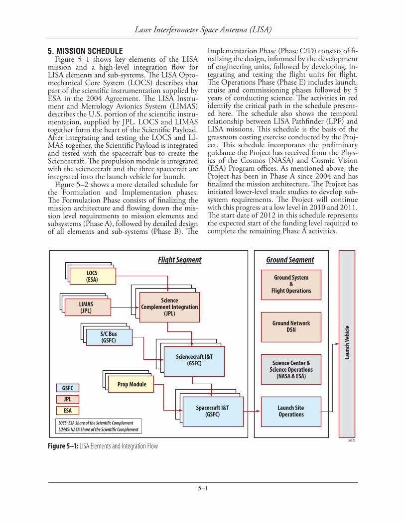
5. MISSION SCHEDULEFigure 5–1 shows key elements of the LISA
mission and a high-level integration flow for LISA elements and sub-systems. The LISA Opto-mechanical Core System (LOCS) describes that part of the scientific instrumentation supplied by ESA in the 2004 Agreement. The LISA Instru-ment and Metrology Avionics System (LIMAS) describes the U.S. portion of the scientific instru-mentation, supplied by JPL. LOCS and LIMAS together form the heart of the Scientific Payload. After integrating and testing the LOCS and LI-MAS together, the Scientific Payload is integrated and tested with the spacecraft bus to create the Sciencecraft. The propulsion module is integrated with the sciencecraft and the three spacecraft are integrated into the launch vehicle for launch.
Figure 5–2 shows a more detailed schedule for the Formulation and Implementation phases. The Formulation Phase consists of finalizing the mission architecture and flowing down the mis-sion level requirements to mission elements and subsystems (Phase A), followed by detailed design of all elements and sub-systems (Phase B). The
Figure 5–1: LISA Elements and Integration Flow
Implementation Phase (Phase C/D) consists of fi-nalizing the design, informed by the development of engineering units, followed by developing, in-tegrating and testing the flight units for flight. The Operations Phase (Phase E) includes launch, cruise and commissioning phases followed by 5 years of conducting science. The activities in red identify the critical path in the schedule present-ed here. The schedule also shows the temporal relationship between LISA Pathfinder (LPF) and LISA missions. This schedule is the basis of the grassroots costing exercise conducted by the Proj-ect. This schedule incorporates the preliminary guidance the Project has received from the Phys-ics of the Cosmos (NASA) and Cosmic Vision (ESA) Program offices. As mentioned above, the Project has been in Phase A since 2004 and has finalized the mission architecture. The Project has initiated lower-level trade studies to develop sub-system requirements. The Project will continue with this progress at a low level in 2010 and 2011. The start date of 2012 in this schedule represents the expected start of the funding level required to complete the remaining Phase A activities.
LA023
Flight Segment Ground SegmentLOCS(ESA)
LIMAS(JPL)
S/C Bus(GSFC)
Prop Module
ScienceComplement Integration
(JPL)
Sciencecraft I&T(GSFC)
Spacecraft I&T(GSFC)
GSFC
JPL
ESA
Ground System&
Flight Operations
Ground NetworkDSN
Science Center &Science Operations
(NASA & ESA)
Launch Site Operations
LOCS: ESA Share of the Scienti�c ComplementLIMAS: NASA Share of the Scienti�c Complement
Laun
ch Ve
hicle

5–2
Laser Interferometer Space Antenna (LISA)
LA027
Figure 5–2: LISA Integrated Schedule
6–1
Laser Interferometer Space Antenna (LISA)
6. LISA MISSION LIFECYCLE COST ESTIMATE
BackgroundSince the formal inception of the LISA project
in 2001, four major costing exercises have been conducted to update the LISA mission Life Cycle Cost (LCC). The Project completed a parametric based analysis in 2003, and, a bottoms-up grass-roots exercise in 2008. The other two estimates were independently conducted by Aerospace Corporation and SAIC under the direction of the Technology Readiness & Implementation Review Team (2003) and the Beyond Einstein Program Assessment Committee (BEPAC) in 2007. LISA’s measurement concept and the mission architec-ture have remained constant throughout these ex-ercises. With the exception of the BEPAC led es-timate, all other estimates have been within 20% of each other at ~$1.2B (Real Years) for NASA’s share. The project grassroots and the BEPAC LCC estimates are presented herein, with an at-tempt to identify factors causing the difference between the two. Aerospace Corporation is con-ducting another independent cost estimate based on the directions from NASA Headquarters. An updated LCC will be provided to the committee once the Aerospace estimate is available.
ApproachWith the exception of the grassroots estimate,
all exercises estimated the total mission cost in US dollars and then determined NASA cost share by subtracting the dollar value for the elements pro-vided by ESA. This approach is no longer valid since ESA’s commitment to contribute €650M (Fixed Year 2007) for a “Large” mission has been formalized in their Cosmic Vision Program Plan. What ESA will deliver for €650M cannot be translated simply to US dollars because of the dif-
ferences in accounting practices between Europe and the US. The LISA Project took the follow-ing approach for estimating NASA’s share of the LCC:
Both Agencies developed grassroots estimates for all elements, sub-systems and components the Agency could possibly be responsible for. NASA estimates were produced by GSFC and JPL orga-nizations with expertise in the given subsystem. ESA cost estimates are anchored to the develop-ment costs for LISA Pathfinder (LPF). Using the component level cost data the NASA and ESA projects jointly developed several scenarios for the division of responsibilities by allocating WBS ele-ments to either NASA or ESA such that:• ESA budget commitment of €650M is fully
utilized• Lead and supporting roles are clearly assigned • Interfaces are simple and clear • Responsibilities are consistent with the tech-
nology development investments already made by the Agencies
• Resulting organizational structure supports mission success
• Deliverables are compatible with ITAR regula-tionsSix scenarios meeting the above criteria were
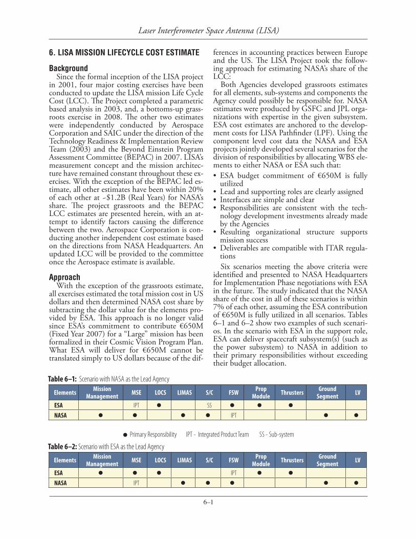
identified and presented to NASA Headquarters for Implementation Phase negotiations with ESA in the future. The study indicated that the NASA share of the cost in all of these scenarios is within 7% of each other, assuming the ESA contribution of €650M is fully utilized in all scenarios. Tables 6–1 and 6–2 show two examples of such scenari-os. In the scenario with ESA in the support role, ESA can deliver spacecraft subsystem(s) (such as the power subsystem) to NASA in addition to their primary responsibilities without exceeding their budget allocation.
Table 6–1: Scenario with NASA as the Lead Agency
Elements Mission Management MSE LOCS LIMAS S/C FSW Prop
Module Thrusters Ground Segment LV
ESA IPT l SS l l l
NASA l l l l IPT l l
Table 6–2: Scenario with ESA as the Lead Agency
Elements Mission Management MSE LOCS LIMAS S/C FSW Prop
Module Thrusters Ground Segment LV
ESA l l l IPT l l
NASA IPT l l l l l
l Primary Responsibility IPT - Integrated Product Team SS - Sub-system

6–2
Laser Interferometer Space Antenna (LISA)
Detailed NASA Cost Detailed cost information for the scenario
yielding the largest NASA cost is presented in this Section. Table 6–3 shows the cost break-down for the key mission phases. The “Institu-tional” row presents the results from the detailed grassroots estimate conducted by the Project. Ac-cording to NASA policy, the yearly cost profile resulting from the “Institutional” costing exercise is not provided in this submittal since it is not yet endorsed as being at a 70% Confidence Level (CL). The “BEPAC” row presents the range of estimates at 70% CL, independently developed by BEPAC. It should be noted that the BEPAC estimates were provided in Real Year (RY) dollars. We have made a best effort possible to convert the BEPAC data to Fixed Year 09, using the limited information available in the BEPAC report. The next subsection provides a more detailed compar-ison between the Project and BEPAC estimates in RY dollars. BEPAC estimates did not include Phases A and B. As mentioned before, the Aero-space Corporation is conducting an independent cost estimate for LISA. Once available, that data will be provided to the committee as well.
Table 6–4 provides further cost breakdown for the Operations Phase, based on the Institutional cost estimate.
Based on this scenario, the total Mission LCC is estimated at $896M plus €650M. Although the units are a mix of Dollars and Euros, this is the
best way to represent the total LCC at this time. The LISA project will continue to make prog-
ress towards completing Phase A activities in 2010 and 2011 and will require ~ $6M in each of these years. During this period the Project will mature the Phase Measurement System to TRL-6, dem-onstrate microthruster lifetime compatibility, and con tinue meaningful participation with ESA in mis sion requirements development.
Comparison with BEPAC estimateAs mentioned above, the Project LCC pre-
sented here is based on a detailed, sub-system and element level grassroots costing exercise. Table 6–5 is presented here to illustrate the depth of the Project costing exercise as well as for further comparison with the BEPAC cost estimate. The data presented in this table are in Real Year (RY) dollars, since the BEPAC estimate is also available in RY dollars.
As part of their charter, the BEPAC conduct-ed parametric based independent cost estimates for all the missions being reviewed in 2007. The BEPAC estimated total LISA mission LCC to be between $3.2 and $3.6B (RY). • Mission Development: $2,318M• Launch Services: $300M• Phase E; Mission Operations & Data Analysis
(MO&DA): $641MBEPAC then applied a $500M credit as the
ESA contribution for the Mission development, resulting in the NASA share of $2.76B. When compared to the Project’s grassroots estimate of $1.175B (RY), the BEPAC estimate for the NASA share is more than twice the Project estimate.
The BEPAC did not provide a detailed expla-nation of how they arrived at their estimate. The differences in the cost estimates can possibly be attributed to the differences in the assumptions used for MO&DA, Complexity Factor and ESA Contribution, as described below:• The BEPAC estimate may have assumed a Hub-
ble-like MO&DA concept. LISA is a single in-strument mission with an all-sky instrument and a single mode of operation for science data collection, similar to WMAP.
• BEPAC assigned a high Degree Of Difficulty (IV) to the GRS and Thrusters. This assessment does not account for the fact that both of these sub-systems have made significant progress in the LPF program. The Flight Model Colloidal Micronewton Thrusters have successfully com-pleted the Integration, Verification and Testing program and are ready to be shipped to ESA.
Table 6–4: Operations Phase Cost Breakdown (FY09)Operations Phase $M
Mission Operations 92
Science Operations/Science Center 26
Guest Investigator 28
Table 6–3: Cost Summary Table (NASA’s Share)LISA mission Cost Breakdown $M (Fixed Year 09)
Phase A Phase B Phases CD
Launch Services
Phase E LCC
Institutional $14 $63 $488 $185 $146 $896
BEPAC 70% CL
Not Available
Not Available
$1,700- $1,270 $266 $494 $2,460-
$2,03035% Reserves for Development Phases15% Reserves for Operations PhaseSchedule durations: A = 12 months (Represents duration to complete remaining activities) B = 30 monthsCD = 66 monthsEF = 74 months (Including cruise & commissioning phase)

6–3
Laser Interferometer Space Antenna (LISA)
Table 6–5: WBS Level Details for NASA’s Share (RY) WBS WBS Title Cost ($K)
1.1 Project Management $61,272
GSFC Management $42,890
JPL Management $18,382
1.3 LOCS Sub Systems –
1.2 Systems Engineering $24,620
1.4 LIMAS $78,143
1.5 Sciencecraft (S/C) $265,468
Attitude Control System (ACS) $24,019
Avionics/C&DH System $40,873
Flight S/W $36,660
Power $36,110
Communication (Comm) $48,296
Mechanical $30,406
Thermal $12,725
GSE & Ground Segment $4,460
S/C I&T $18,202
S/C Management & Sys Engr $13,717
1.6 Systems I&T $23,602
GSFC Sciencecraft I&T $12,250
System Level I&T $8,370
Launch Stack Integration $681
Launch Campaign $310
LOCS-LIMAS I&T $1,991
1.8 Ground Segment $106,997
Mission Operations System $62,332
Ground Data System $34,772
Mission Design $9,893
1.9 Software Independent Verification & Validation –
1.10 Launch Services $243,400
1.11 NASA Mission Assurance $42,890
GSFC Mission Assurance $21,874
JPL Mission Assurance $21,016
1.12 NASA Mission Science $113,888
Mission Science Office $16,053
Science Center $53,054
Guest Investigator Program $44,781
1.13 RTB –
Prop Module –
Thrusters –
Contingency $215,064
TOTAL $1,175,343
The Engineering Model GRS has passed all of the testing and verification activities and the Flight Model is under develop-ment.
• ESA has committed a contribution of €650M towards the mission LCC, based on the economic conditions of 2007. This value will be inflated according to the real inflation rate observed in the ESA mem-ber states. BEPAC’s assumption of $500M grossly underestimates ESA contribution and overestimates NASA cost.In a very simplistic analysis, ESA’s contri-
bution of €650M converted to U.S. dollars yields a minimum of $975M credit, $400M more than that assumed by BEPAC. When combined with the adjustment for the MO&DA cost, the BEPAC estimate can be reduced by more than $800M.