Embed Size (px)
Citation preview

Laser Lissajous.....4/14/15 1 Don Rathjen....Exploratorium Teacher Institute....Pier 15, San Francisco, CA [email protected] © 2015 Exploratorium, www.exploratorium.edu
Laser Lissajous
Use a laser pointer and two small rotating mirrors to create a variety of Lissajous figures.
Figure 1
Materials • 7 PVC 1/2 in. pipe, 2 in. long • 6 PVC 1/2 in. 90 degree elbows • 5 PVC 1/2 in. pipe, 3 in. long • 3 PVC 1/2 in. T • laser pointer • clothespin, wood, with spring • wood base, 3/4 in. x 9 1/4 in. x 3 in. (this is a 3 in. piece of standard 1x10 pine shelving) -- can also use
plywood -- exact dimensions are not critical as long as the base will fit on the frame, and all the components will fit and be functional
• 12 nails, bright finishing, 1 1/2 in, and hammer, OR -- 2 paper clips, masking tape and 2 pieces of 1/2-inch wide double-sided foam tape, 2 in. long (for battery holders -- see Assembly, Step 6)
• hot glue gun and hot glue stick, OR -- 2 pieces of 1/2-inch wide double-sided foam tape, 1 in. long (for mounting potentiometers -- see Assembly, Step 8)
• 4 spring grip broom clips -- available at Home Depot and True Value Hardware • 4 screws, sheet metal, #8 x 5/8 in, pan head, Phillips • 2 motors, 1.5-3 volt -- Kelvin 850647 or Radio Shack 273-223 • 2 potentiometers, 20 or 25 ohm -- Mouser 313-2401-20 or Digi-Key CT2152-ND, or Radio Shack 271-265 • mirror, plastic (plexi-mirror) 1 1/2 in x 1 1/2 in • mirror, plastic (plexi-mirror) 2 in x 2 in • 12 alligator clips -- Radio Shack 270-380 • 6 pieces copper wire, #22, insulated, solid, 6 in. long • screw driver, Phillips • wire stripper • electric drill • needle-nose pliers • 7/64 in drill bit • PVC cutter, or some way to get PVC pipe cut to lengths noted • 5/64 in drill bit • 2 batteries, D • (OPTIONAL) 2 knobs for potentiometers (see Assembly, Step 8) • (OPTIONAL) cable tie, approx 8in (see Assembly, Step 4)

Laser Lissajous.....4/14/15 2 Don Rathjen....Exploratorium Teacher Institute....Pier 15, San Francisco, CA [email protected] © 2015 Exploratorium, www.exploratorium.edu
Assembly 1. Assemble the PVC components to make a stand as shown in Figures 1, 2 and 3. Figure 3 identifies the location of the five 3 in. pieces of pipe. The remaining 7 pieces of pipe are all 2 in.
Figure 2
Figure 3 2. Use the 7/64 in. drill bit to drill a hole near the end of the two 2 in. PVC pieces on which the motors will be mounted. The hole should be near enough to the end of the piece so that when the spring clip and motor are in place, the mirror can rotate freely without hitting the end of the PVC pipe. Use a screw to mount a spring broom clip on each piece. See Figures 1 and 3.
3 in.
Laser Lissajous.....4/14/15 3 Don Rathjen....Exploratorium Teacher Institute....Pier 15, San Francisco, CA [email protected] © 2015 Exploratorium, www.exploratorium.edu
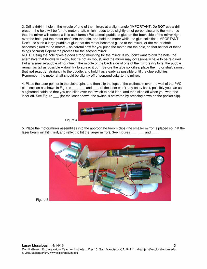
3. Drill a 5/64 in hole in the middle of one of the mirrors at a slight angle (IMPORTANT: Do NOT use a drill press -- the hole will be for the motor shaft, which needs to be slightly off of perpendicular to the mirror so that the mirror will wobble a little as it turns.) Put a small puddle of glue on the back side of the mirror right over the hole, put the motor shaft into the hole, and hold the motor while the glue solidifies (IMPORTANT: Don't use such a large puddle of glue that the motor becomes glued to the mirror, or the motor shaft becomes glued to the motor! -- be careful how far you push the motor into the hole, so that neither of these things occurs!) Repeat the process for the second mirror. NOTE: Using the hole gives a good strong mounting for the mirror. If you don't want to drill the hole, the alternative that follows will work, but it's not as robust, and the mirror may occasionally have to be re-glued. Put a raisin-size puddle of hot glue in the middle of the back side of one of the mirrors (try to let the puddle remain as tall as possible -- don't try to spread it out). Before the glue solidifies, place the motor shaft almost (but not exactly) straight into the puddle, and hold it as steady as possible until the glue solidifies. Remember, the motor shaft should be slightly off of perpendicular to the mirror. 4. Place the laser pointer in the clothespin, and then slip the legs of the clothespin over the wall of the PVC pipe section as shown in Figures ___, ___ and ___. (If the laser won't stay on by itself, possibly you can use a tightened cable tie that you can slide over the switch to hold it on, and then slide off when you want the laser off. See Figure ___ (for the laser shown, the switch is activated by pressing down on the pocket clip).
Figure 4
5. Place the motor/mirror assemblies into the appropriate broom clips (the smaller mirror is placed so that the laser beam will hit it first, and reflect to hit the larger mirror). See Figures ___, ___ and ___.
Figure 5

Laser Lissajous.....4/14/15 4 Don Rathjen....Exploratorium Teacher Institute....Pier 15, San Francisco, CA [email protected] © 2015 Exploratorium, www.exploratorium.edu
6. Use 6 nails for each battery to make battery holders on the wooden base. See Figures 1 and 5 for locations, and Figure 6 for detail. NOTE: For a quicker but less durable mounting of the batteries, use masking tape to tape a paper clip to each end of each battery to serve as electrical contacts (see Figure 7). Then stick a 2 in. piece of foam tape on the bottom of each of the two batteries, remove the backing material, and place the batteries on the base in the appropriate locations.
Figure 6 Figure 7 7. Screw two spring broom clips to the bottom of the wood base so that they are positioned to grip the PVC pipe sections when pressed down onto the frame. See Figures ___ and ___. Snap the base onto the frame.
Figure 8 8. Use hot glue or double-sided foam tape to hold the potentiometers on the base in the approximate positions shown in Figures ___ and ___. NOTE: If you wish, you can buy knobs for the potentiometers. The knobs make the potentiometers a little easier to adjust, but are definitely optional. 9. Use a wire stripper to remove the insulation on the ends of the 6 wires. 10. Use needle-nose pliers to attach an alligator clip to each end of each wire. Figures 9 a-d show a sequence for one way to attach the clip securely.
Figure 9a Figure 9b Figure 9c Figure 9d Stick bare end of wire Bend bare end back and Bend near tab down to Bend far tab down down through hole. upward, between tabs. fasten bare wire against tightly over near tab. insulated wire. 11. For one of the mirrors, wire the motor, battery and potentiometer in series. Repeat for the other mirror. On the potentiometers, use the middle contact and either of the outside contacts. To make the potentiometer shaft rotate the opposite way to increase speed, keep the middle contact but change the outside contact to the other one. To make the mirror turn in the opposite direction, reverse the leads on the motor contacts.

Laser Lissajous.....4/14/15 5 Don Rathjen....Exploratorium Teacher Institute....Pier 15, San Francisco, CA [email protected] © 2015 Exploratorium, www.exploratorium.edu
To Do and Notice Turn the laser on. Adjust the positions of the laser and mirrors until the laser beam bounces off the
first mirror, then the second mirror, and is finally seen on a screen. If all is well, when you turn either mirror alone (either by hand or with the motor) you should see a circle or ellipse on the screen. If you don't, the laser beam is missing all or part of one or both of the mirrors, or is getting blocked in some way. Make adjustments in the mirror and laser positions as necessary. Note that the spring clip can be turned by itself, the clip and the pipe to which it is screwed can be rotated, the three piece unit of clip-pipe-elbow can be turned, and the entire section from the elbow to the clip can be tilted. Also, the clothespin can be moved to some extent to adjust the position of the laser
Use the motors to rotate the mirrors in opposite directions (e.g., one clockwise and the other counterclockwise as observed from the same end of the device). Notice the variety of patterns (Lissajous figures) produced as you vary the speeds of the motors.
Reverse the leads on one motor so that the mirrors are now rotating in the same direction, and notice the difference in the patterns compared to the mirrors rotating in opposite directions. What's Going On?
Very briefly, the Lissajous figures produced here are the resultant of two simultaneous circular motions. They are related to figures produced by a spirograph, or to the path of a rider on a dual-axis "scrambler" ride at an amusement park. The diagram and explanation that follow provide a detailed description of one example of pattern formation.
Laser Lissajous.....4/14/15 6 Don Rathjen....Exploratorium Teacher Institute....Pier 15, San Francisco, CA [email protected] © 2015 Exploratorium, www.exploratorium.edu
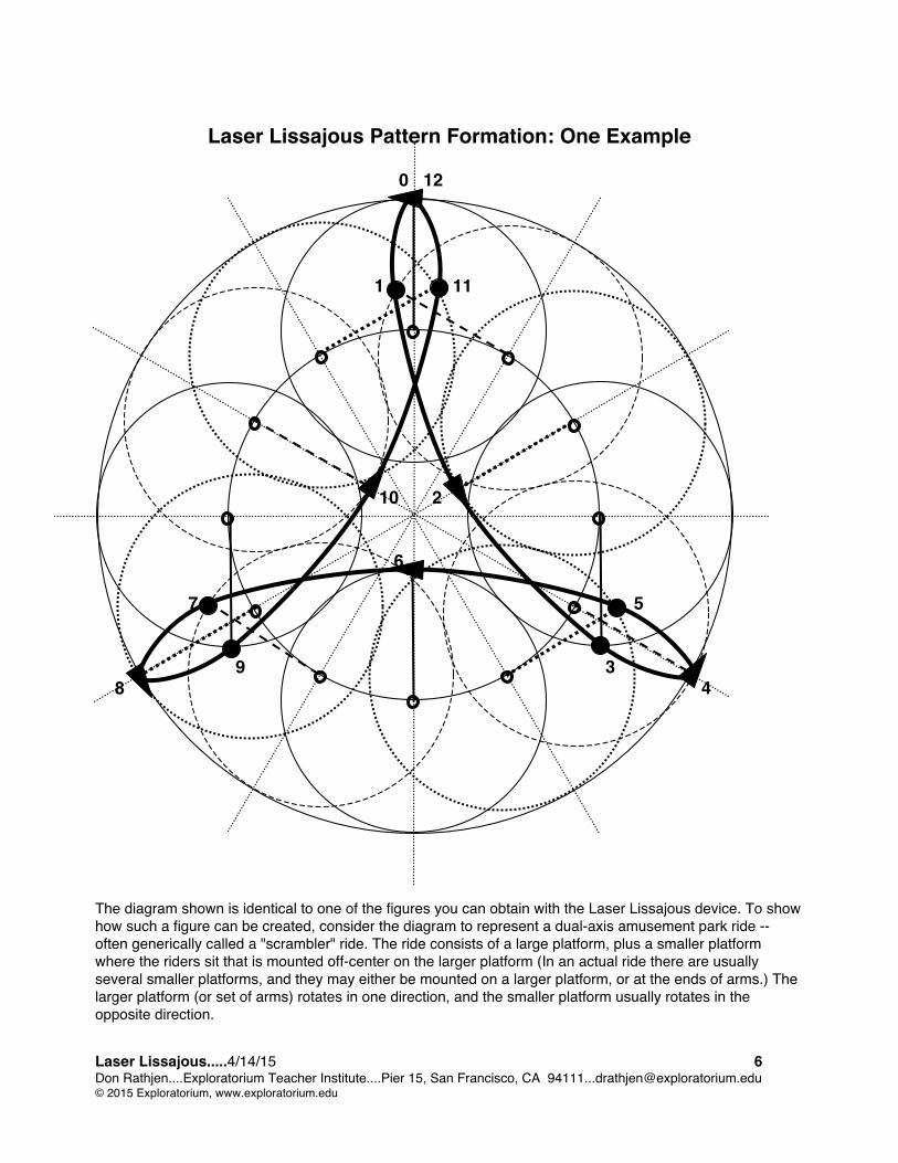
Laser Lissajous Pattern Formation: One Example
0 12 1 11 10 2 6 7 5 9 3 8 4 The diagram shown is identical to one of the figures you can obtain with the Laser Lissajous device. To show how such a figure can be created, consider the diagram to represent a dual-axis amusement park ride -- often generically called a "scrambler" ride. The ride consists of a large platform, plus a smaller platform where the riders sit that is mounted off-center on the larger platform (In an actual ride there are usually several smaller platforms, and they may either be mounted on a larger platform, or at the ends of arms.) The larger platform (or set of arms) rotates in one direction, and the smaller platform usually rotates in the opposite direction.

Laser Lissajous.....4/14/15 7 Don Rathjen....Exploratorium Teacher Institute....Pier 15, San Francisco, CA [email protected] © 2015 Exploratorium, www.exploratorium.edu
The diagram shows a large platform (large circle around the perimeter) with a single smaller platform (small circle) shown at 12 successive positions in time (the 12 positions being the 12 hours on a clock). The large platform rotates clockwise around it's center, and the smaller platform simultaneously rotates counterclockwise around it's own center. Let's follow a rider's movement, or path, from position 0 (12 o'clock) through position 4 (4 o'clock). At position 0, the rider is at the 12 o'clock position on both platforms. When the larger platform has rotated 1/12 of a revolution clockwise, the center of the smaller platform (noted with a small bold circle), has moved to the 1 o'clock position. But at the same time, the smaller platform has been rotating three times as fast (3/12 of a revolution) in the counterclockwise direction. The rider's clock position on the smaller platform itself has changed from 12 o'clock to 9 o'clock. (The rider's new position is shown at the end of the dark dashed radius.) The rider's overall new position as a result of both rotations is shown as position 1. When the larger platform has rotated 2/12 of a revolution clockwise, the center of the smaller platform (again noted with a small bold circle), has moved to the 2 o'clock position. Again the smaller platform has been rotating three times as fast in the counterclockwise direction (6/12 of a revolution), and the rider's clock position on the smaller platform itself has changed from 12 o'clock to 6 o'clock. (The rider's position is shown at the end of the dark dotted radius.) The rider's overall new position as a result of both rotations is shown as position 2. Similar changes occur for the for 3/12 and 4/12 of a revolution, with the rider's positions shown as positions 3 and 4. The remainder of the ride turns out to be two more symmetrical repetitions of this first segment. Note that the rider is tangent to the outer circle three times in the course of one revolution of the large platform. This has to do with the fact that the smaller platform is rotating three times faster than the larger platform. If the speed ratio was 4:1 rather than 3:1, there would be four tangent points in one revolution. There are other variables that can radically change the character of the figures, among them the radii of the two platforms, and whether they are rotating in the same direction or in opposite directions. For the actual mathematics of the situation, look up curves such as trochoids, roulettes, epicycloids and hypocycloids, and their corresponding equations. The MSN Encarta dictionary definition of Lissajous Figure is:
curve from combining two vibrations: the mathematical curve formed by combining two repeating vibrations that are at right angles to each other [Late 19th century. After Jules Antoine Lissajous (1822-1880), French physicist]."
So strictly speaking, the figures produced with the Laser Lissajous device may not technically be Lissajous figures (the key phrase being "...at right angles to each other..."). But they are at the very least "Lissajous-like" figures!
Laser Lissajous.....4/14/15 8 Don Rathjen....Exploratorium Teacher Institute....Pier 15, San Francisco, CA [email protected] © 2015 Exploratorium, www.exploratorium.edu
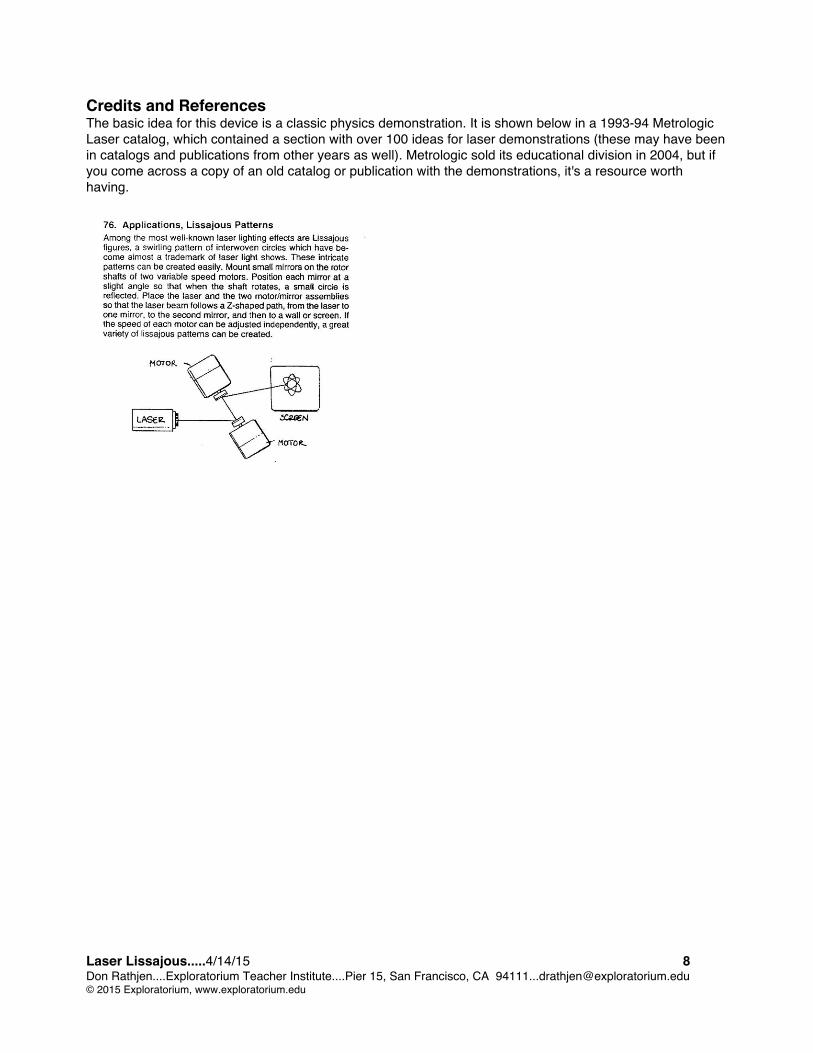
Credits and References The basic idea for this device is a classic physics demonstration. It is shown below in a 1993-94 Metrologic Laser catalog, which contained a section with over 100 ideas for laser demonstrations (these may have been in catalogs and publications from other years as well). Metrologic sold its educational division in 2004, but if you come across a copy of an old catalog or publication with the demonstrations, it's a resource worth having.


![Superintegrable Lissajous systems on the sphere · 2018-10-09 · arXiv:1404.7064v1 [math-ph] 28 Apr 2014 Superintegrable Lissajous systems on the sphere J.A. Calzada1, S¸.Kuru2,](https://img.pdfslide.net/doc/110x75/5f21c1bc50d86527771350ec/superintegrable-lissajous-systems-on-the-sphere-2018-10-09-arxiv14047064v1-math-ph.jpg)