Embed Size (px)
Citation preview
46 jec composites magazine / No105 June 2016
laser cutting
Laser machining of CFRP
up to 70% lighter than steel and 30% lighter than aluminium [2]. These advantages are what also makes CFRP attractive for use in many non-transportation related industries such as components for wind energy production, sports equipment, oil exploration equipment, and even some consumer electronics products.The attributes that make CFRPs very unique and useful materials also make them difficult to machine with high quality. Manufac-turers using CFRP in their products are also looking to decrease fabrication costs. As material costs continue to decline, the demand for CFRP materials overall will further increase.
Types of machiningConventional mechanical machining techniques used with CFRP are costly due to high tool wear and operating costs. Fibre frac-ture and material delamination are common during machining, resulting in yield loss. The more commonly used abrasive waterjet technique provides high-quality machining without any thermal damage. However, it is a very noisy process with potential fibre damage due to the high-pressure jet, and water and abrasive particles can get trapped in the material and lead to yield loss. While the use of lasers for CFRP machining is in its early stages, lasers have been successfully adopted in the manufacturing indus-try for machining various metals. Lasers provide the advantages
The use of lasers for CFRP machining offers the advantages of a non-contact process and ease of automation, while eliminating tool wear, lowe-ring operating costs and reducing or eliminating fibre damage and material delamination. But the current challenge is to find a laser source and pro-cess that can deliver a good balance of speed and quality. The Quasar UV pulsed hybrid fibre lasers developed by Spectra-Physics are a promising tool for high-quality, high-speed CFRP processing.
Carbon fibre-reinforced polymers or plastics (CFRP) are widely used across various industries such as aerospace, automotive, wind energy, oil & gas and sports equipment.
A strong desire to increase fuel efficiency and reduce carbon emissions in the aerospace and automotive industries is driving the use of CFRP materials in the fabrication of various aircraft and automotive parts. For automobiles, a 10% reduction in weight typically leads to a 6-8% reduction in fuel consumption. The corporate average fuel economy (CAFE) standards in the US will require auto manufacturers to achieve a fleet average of 35.5 miles per gallon (mpg) by 2016 and then hit 54.5 mpg by 2025. In the European Union, CO2 emission limits for passenger cars will be reduced from 130 gm of CO2/km in 2015 to a much more challenging 95 gm of CO2/km by 2020 [1]. CFRPs are lightweight, strong, durable materials with good cor-rosion and vibration resistance. They are good candidates to re-place many metal parts. An optimally designed CFRP part can be
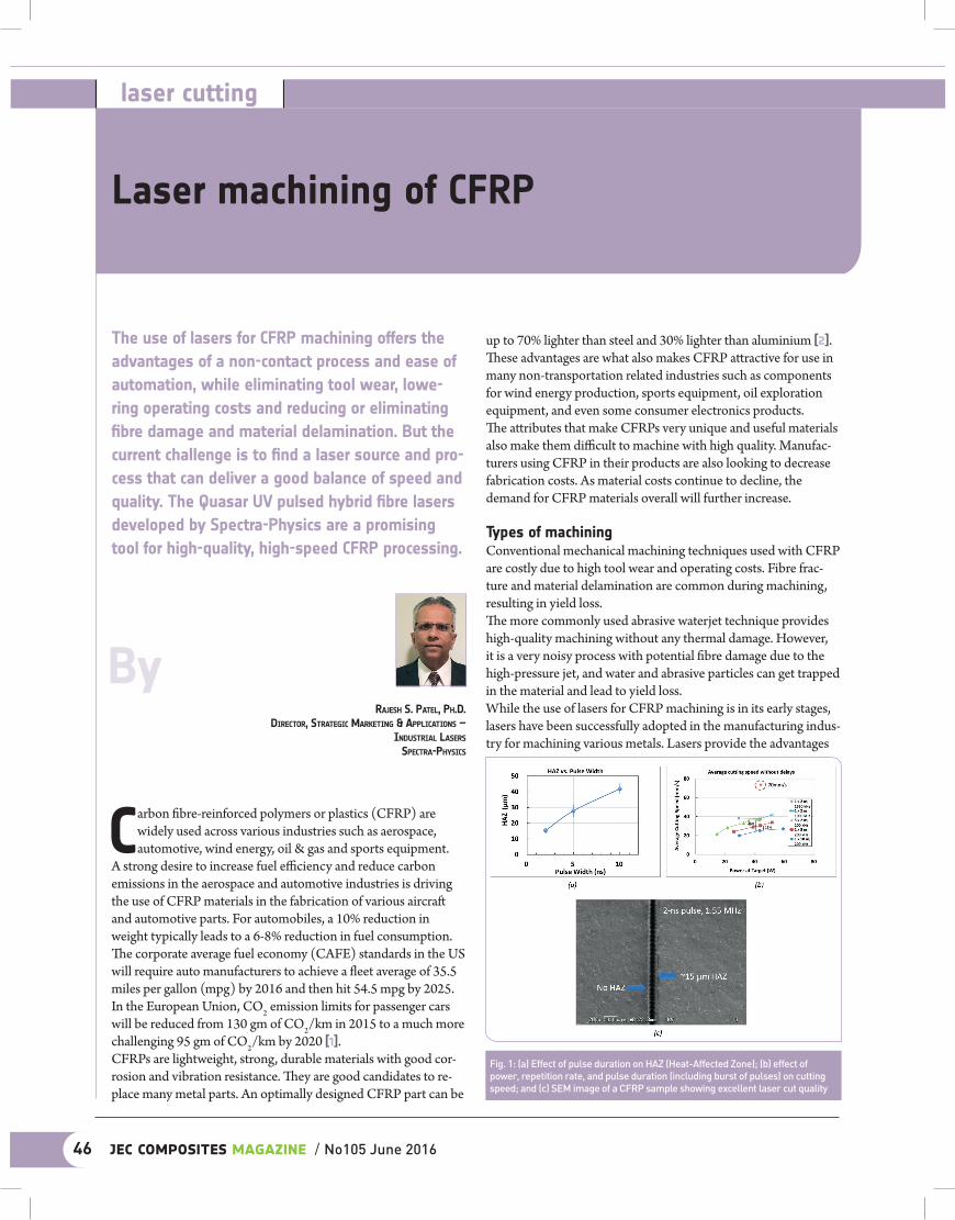
ByRajesh s. Patel, Ph.D.
DiRectoR, stRategic MaRketing & aPPlications – inDustRial laseRs
sPectRa-Physics
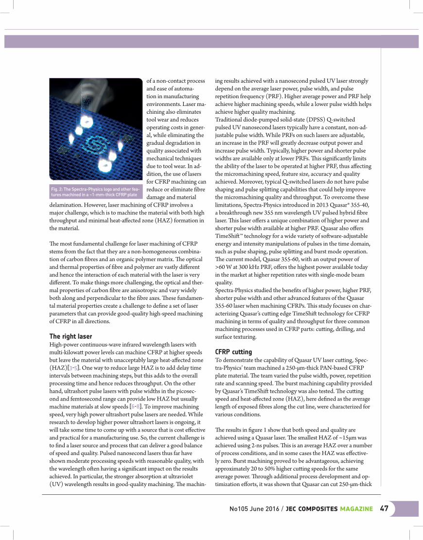
Fig. 1: (a) Effect of pulse duration on HAZ (Heat-Affected Zone); (b) effect of power, repetition rate, and pulse duration (including burst of pulses) on cutting speed; and (c) SEM image of a CFRP sample showing excellent laser cut quality
of a non-contact process and ease of automa-tion in manufacturing environments. Laser ma-chining also eliminates tool wear and reduces operating costs in gener-al, while eliminating the gradual degradation in quality associated with mechanical techniques due to tool wear. In ad-dition, the use of lasers for CFRP machining can reduce or eliminate fibre damage and material
delamination. However, laser machining of CFRP involves a major challenge, which is to machine the material with both high throughput and minimal heat-affected zone (HAZ) formation in the material.
The most fundamental challenge for laser machining of CFRP stems from the fact that they are a non-homogeneous combina-tion of carbon fibres and an organic polymer matrix. The optical and thermal properties of fibre and polymer are vastly different and hence the interaction of each material with the laser is very different. To make things more challenging, the optical and ther-mal properties of carbon fibre are anisotropic and vary widely both along and perpendicular to the fibre axes. These fundamen-tal material properties create a challenge to define a set of laser parameters that can provide good-quality high-speed machining of CFRP in all directions.
The right laserHigh-power continuous-wave infrared wavelength lasers with multi-kilowatt power levels can machine CFRP at higher speeds but leave the material with unacceptably large heat-affected zone (HAZ)[3-5]. One way to reduce large HAZ is to add delay time intervals between machining steps, but this adds to the overall processing time and hence reduces throughput. On the other hand, ultrashort pulse lasers with pulse widths in the picosec-ond and femtosecond range can provide low HAZ but usually machine materials at slow speeds [6-8]. To improve machining speed, very high power ultrashort pulse lasers are needed. While research to develop higher power ultrashort lasers is ongoing, it will take some time to come up with a source that is cost effective and practical for a manufacturing use. So, the current challenge is to find a laser source and process that can deliver a good balance of speed and quality. Pulsed nanosecond lasers thus far have shown moderate processing speeds with reasonable quality, with the wavelength often having a significant impact on the results achieved. In particular, the stronger absorption at ultraviolet (UV) wavelength results in good-quality machining. The machin-
ing results achieved with a nanosecond pulsed UV laser strongly depend on the average laser power, pulse width, and pulse repetition frequency (PRF). Higher average power and PRF help achieve higher machining speeds, while a lower pulse width helps achieve higher quality machining.Traditional diode-pumped solid-state (DPSS) Q-switched pulsed UV nanosecond lasers typically have a constant, non-ad-justable pulse width. While PRFs on such lasers are adjustable, an increase in the PRF will greatly decrease output power and increase pulse width. Typically, higher power and shorter pulse widths are available only at lower PRFs. This significantly limits the ability of the laser to be operated at higher PRF, thus affecting the micromachining speed, feature size, accuracy and quality achieved. Moreover, typical Q-switched lasers do not have pulse shaping and pulse splitting capabilities that could help improve the micromachining quality and throughput. To overcome these limitations, Spectra-Physics introduced in 2013 Quasar® 355-40, a breakthrough new 355 nm wavelength UV pulsed hybrid fibre laser. This laser offers a unique combination of higher power and shorter pulse width available at higher PRF. Quasar also offers TimeShift™ technology for a wide variety of software-adjustable energy and intensity manipulations of pulses in the time domain, such as pulse shaping, pulse splitting and burst mode operation. The current model, Quasar 355-60, with an output power of >60 W at 300 kHz PRF, offers the highest power available today in the market at higher repetition rates with single-mode beam quality.Spectra-Physics studied the benefits of higher power, higher PRF, shorter pulse width and other advanced features of the Quasar 355-60 laser when machining CFRPs. This study focuses on char-acterizing Quasar’s cutting edge TimeShift technology for CFRP machining in terms of quality and throughput for three common machining processes used in CFRP parts: cutting, drilling, and surface texturing.
CFRP cuttingTo demonstrate the capability of Quasar UV laser cutting, Spec-tra-Physics’ team machined a 250-µm-thick PAN-based CFRP plate material. The team varied the pulse width, power, repetition rate and scanning speed. The burst machining capability provided by Quasar’s TimeShift technology was also tested. The cutting speed and heat-affected zone (HAZ), here defined as the average length of exposed fibres along the cut line, were characterized for various conditions.
The results in figure 1 show that both speed and quality are achieved using a Quasar laser. The smallest HAZ of ~15µm was achieved using 2-ns pulses. This is an average HAZ over a number of process conditions, and in some cases the HAZ was effective-ly zero. Burst machining proved to be advantageous, achieving approximately 20 to 50% higher cutting speeds for the same average power. Through additional process development and op-timization efforts, it was shown that Quasar can cut 250-µm-thick
Fig. 2: The Spectra-Physics logo and other fea-tures machined in a ~1-mm-thick CFRP plate
No105 June 2016 / jec composites magazine 47
moulding process. A thorough cleaning and surface texturing of the part without damaging the fibres is crucial to achieve higher joint strength.Painting of CFRP parts is also challenging due to a low surface wettability and poor surface adhesion, both of which can be improved with laser processing. A thorough cleaning and textur-ing of the surface prior to painting improves the wettability and hence the adhesion of paint to the surface. The commonly used CFRP surface cleaning and texturing tech-niques are peel-plies and mechanical abrading (or grit blasting). While the peel-ply technique can provide a reproducible surface roughness, it requires the lamination of peel-plies onto the surface prior to moulding and hence adds manufacturing steps and costs. The repeatability of the peel-ply process is questionable since the thickness of the top resin layer after the peel-ply process tends to vary across the part surface. Moreover, release agent residues can be transferred from the peel-ply onto the part and hence affect the joint strength. The major disadvantages of mechanical abrading are its low throughput speed and the use of wet chemicals. Hence, a sub-sequent rinsing and drying of the part is necessary, which adds manufacturing steps and costs. Additionally, this technique is usually performed manually, making it very time consuming and difficult to implement for large CFRP parts. It also has a high pro-cess variability and the risk of damaging fibres. The grit blasting technique tends to damage fibres and leaves residues and dust on the part, thus implying a subsequent cleaning and drying.To overcome the limitations of peel-ply and mechanical abrading techniques, lasers have been considered as an effective tool for the pre-treatment of CFRP parts for cleaning and texturing the surface. Lasers are known to provide a dry, non-contact, precisely controlled high-speed process. Research shows that parts pre-treated using UV and near-infrared (IR) lasers can achieve a lap shear strength similar to that of an abraded part [9]. However, the high absorption of UV laser radiation inside the matrix material compared to near IR laser is useful to avoid possible material
CFRP plates at 70 mm/sec with an HAZ of < 15 µm.Using the optimized laser process parameters, the team was also successful in cutting a thicker ~1-mm-thick CFRP plate, as shown in figure 2.
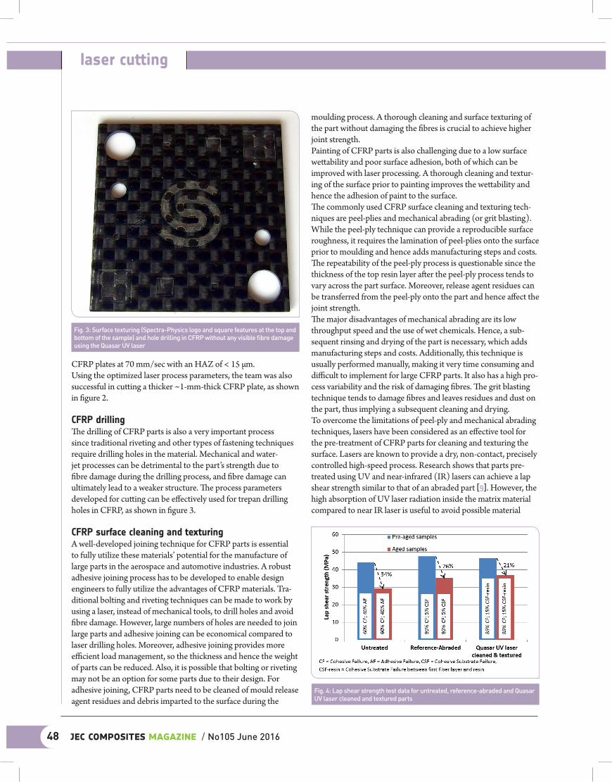
CFRP drillingThe drilling of CFRP parts is also a very important process since traditional riveting and other types of fastening techniques require drilling holes in the material. Mechanical and water-jet processes can be detrimental to the part’s strength due to fibre damage during the drilling process, and fibre damage can ultimately lead to a weaker structure. The process parameters developed for cutting can be effectively used for trepan drilling holes in CFRP, as shown in figure 3.
CFRP surface cleaning and texturingA well-developed joining technique for CFRP parts is essential to fully utilize these materials’ potential for the manufacture of large parts in the aerospace and automotive industries. A robust adhesive joining process has to be developed to enable design engineers to fully utilize the advantages of CFRP materials. Tra-ditional bolting and riveting techniques can be made to work by using a laser, instead of mechanical tools, to drill holes and avoid fibre damage. However, large numbers of holes are needed to join large parts and adhesive joining can be economical compared to laser drilling holes. Moreover, adhesive joining provides more efficient load management, so the thickness and hence the weight of parts can be reduced. Also, it is possible that bolting or riveting may not be an option for some parts due to their design. For adhesive joining, CFRP parts need to be cleaned of mould release agent residues and debris imparted to the surface during the
Fig. 4: Lap shear strength test data for untreated, reference-abraded and Quasar UV laser cleaned and textured parts
Fig. 3: Surface texturing (Spectra-Physics logo and square features at the top and bottom of the sample) and hole drilling in CFRP without any visible fibre damage using the Quasar UV laser
48 jec composites magazine / No105 June 2016
laser cutting
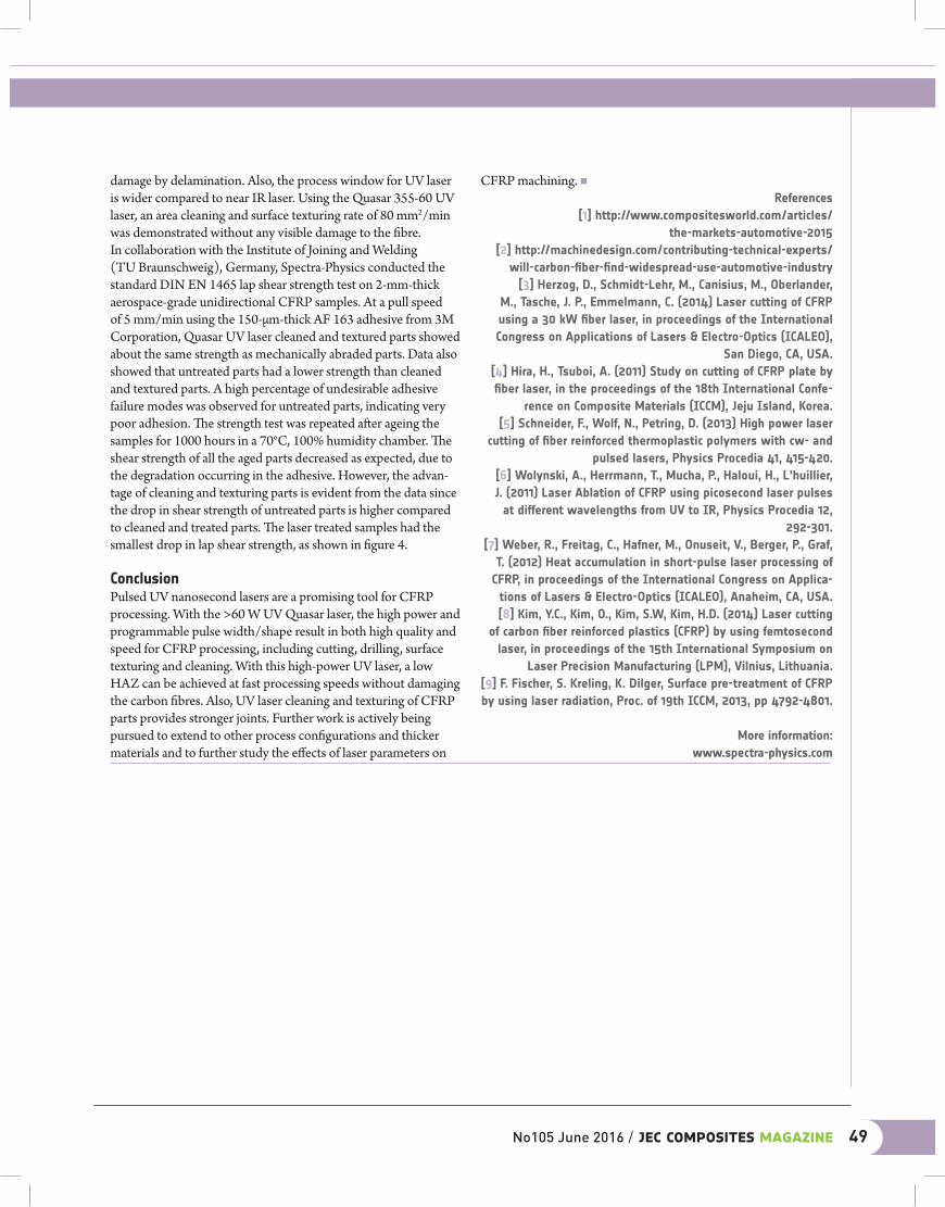
damage by delamination. Also, the process window for UV laser is wider compared to near IR laser. Using the Quasar 355-60 UV laser, an area cleaning and surface texturing rate of 80 mm2/min was demonstrated without any visible damage to the fibre.In collaboration with the Institute of Joining and Welding (TU Braunschweig), Germany, Spectra-Physics conducted the standard DIN EN 1465 lap shear strength test on 2-mm-thick aerospace-grade unidirectional CFRP samples. At a pull speed of 5 mm/min using the 150-µm-thick AF 163 adhesive from 3M Corporation, Quasar UV laser cleaned and textured parts showed about the same strength as mechanically abraded parts. Data also showed that untreated parts had a lower strength than cleaned and textured parts. A high percentage of undesirable adhesive failure modes was observed for untreated parts, indicating very poor adhesion. The strength test was repeated after ageing the samples for 1000 hours in a 70°C, 100% humidity chamber. The shear strength of all the aged parts decreased as expected, due to the degradation occurring in the adhesive. However, the advan-tage of cleaning and texturing parts is evident from the data since the drop in shear strength of untreated parts is higher compared to cleaned and treated parts. The laser treated samples had the smallest drop in lap shear strength, as shown in figure 4. ConclusionPulsed UV nanosecond lasers are a promising tool for CFRP processing. With the >60 W UV Quasar laser, the high power and programmable pulse width/shape result in both high quality and speed for CFRP processing, including cutting, drilling, surface texturing and cleaning. With this high-power UV laser, a low HAZ can be achieved at fast processing speeds without damaging the carbon fibres. Also, UV laser cleaning and texturing of CFRP parts provides stronger joints. Further work is actively being pursued to extend to other process configurations and thicker materials and to further study the effects of laser parameters on
CFRP machining. nReferences
[1] http://www.compositesworld.com/articles/ the-markets-automotive-2015
[2] http://machinedesign.com/contributing-technical-experts/will-carbon-fiber-find-widespread-use-automotive-industry
[3] Herzog, D., Schmidt-Lehr, M., Canisius, M., Oberlander, M., Tasche, J. P., Emmelmann, C. (2014) Laser cutting of CFRP using a 30 kW fiber laser, in proceedings of the International Congress on Applications of Lasers & Electro-Optics (ICALEO),
San Diego, CA, USA.[4] Hira, H., Tsuboi, A. (2011) Study on cutting of CFRP plate by fiber laser, in the proceedings of the 18th International Confe-
rence on Composite Materials (ICCM), Jeju Island, Korea.[5] Schneider, F., Wolf, N., Petring, D. (2013) High power laser
cutting of fiber reinforced thermoplastic polymers with cw- and pulsed lasers, Physics Procedia 41, 415-420.
[6] Wolynski, A., Herrmann, T., Mucha, P., Haloui, H., L’huillier, J. (2011) Laser Ablation of CFRP using picosecond laser pulses
at different wavelengths from UV to IR, Physics Procedia 12, 292-301.
[7] Weber, R., Freitag, C., Hafner, M., Onuseit, V., Berger, P., Graf, T. (2012) Heat accumulation in short-pulse laser processing of
CFRP, in proceedings of the International Congress on Applica-tions of Lasers & Electro-Optics (ICALEO), Anaheim, CA, USA.[8] Kim, Y.C., Kim, O., Kim, S.W, Kim, H.D. (2014) Laser cutting
of carbon fiber reinforced plastics (CFRP) by using femtosecond laser, in proceedings of the 15th International Symposium on
Laser Precision Manufacturing (LPM), Vilnius, Lithuania.[9] F. Fischer, S. Kreling, K. Dilger, Surface pre-treatment of CFRP by using laser radiation, Proc. of 19th ICCM, 2013, pp 4792-4801.
More information:www.spectra-physics.com
No105 June 2016 / jec composites magazine 49


![CFRP [Wet-preg]](https://img.pdfslide.net/doc/110x75/546e6828b4af9faa268b4674/cfrp-wet-preg.jpg)