Embed Size (px)
Citation preview
E-1457 3 /98
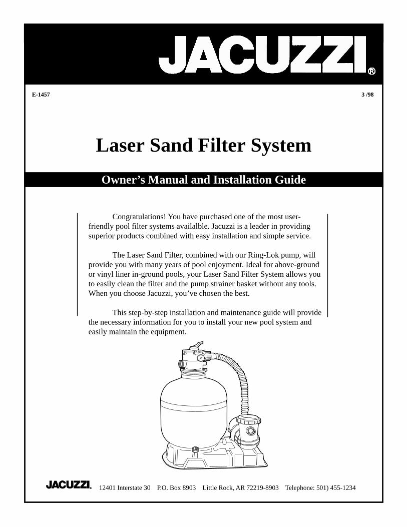
Laser Sand Filter System
Owner’s Manual and Installation Guide
Congratulations! You have purchased one of the most user-friendly pool filter systems availalble. Jacuzzi is a leader in providingsuperior products combined with easy installation and simple service.
The Laser Sand Filter, combined with our Ring-Lok pump, willprovide you with many years of pool enjoyment. Ideal for above-groundor vinyl liner in-ground pools, your Laser Sand Filter System allows youto easily clean the filter and the pump strainer basket without any tools.When you choose Jacuzzi, you’ve chosen the best.
This step-by-step installation and maintenance guide will providethe necessary information for you to install your new pool system andeasily maintain the equipment.
12401 Interstate 30 P.O. Box 8903 Little Rock, AR 72219-8903 Telephone: 501) 455-1234
Introduction:
INSIDE:Setting Up your Equipment...........................4-6
Plumbing The System To Your Pool..................7
Starting Your System......................................8-9
Cleaning The Pump Strainer......................10-11
Cleaning The Filter ........................................12
Winterizing Your Filter System.......................13
Water Maintenance..........................................14
Filter System Parts Breakdown.................14-15
Troubleshooting.........................................16-17
Manufacturer’s Warranty.................................18
○ ○ ○ ○ ○ ○ ○ ○ ○ ○ ○ ○ ○ ○ ○ ○ ○ ○ ○ ○ ○ ○ ○ ○ ○ ○ ○ ○ ○ ○ ○ ○ ○ ○ ○ ○ ○ ○ ○ ○ ○ ○ ○ ○ ○ ○ ○ ○ ○ ○ ○ ○ ○ ○ ○ ○ ○ ○ ○ ○ ○ ○ ○ ○ ○ ○ ○ ○
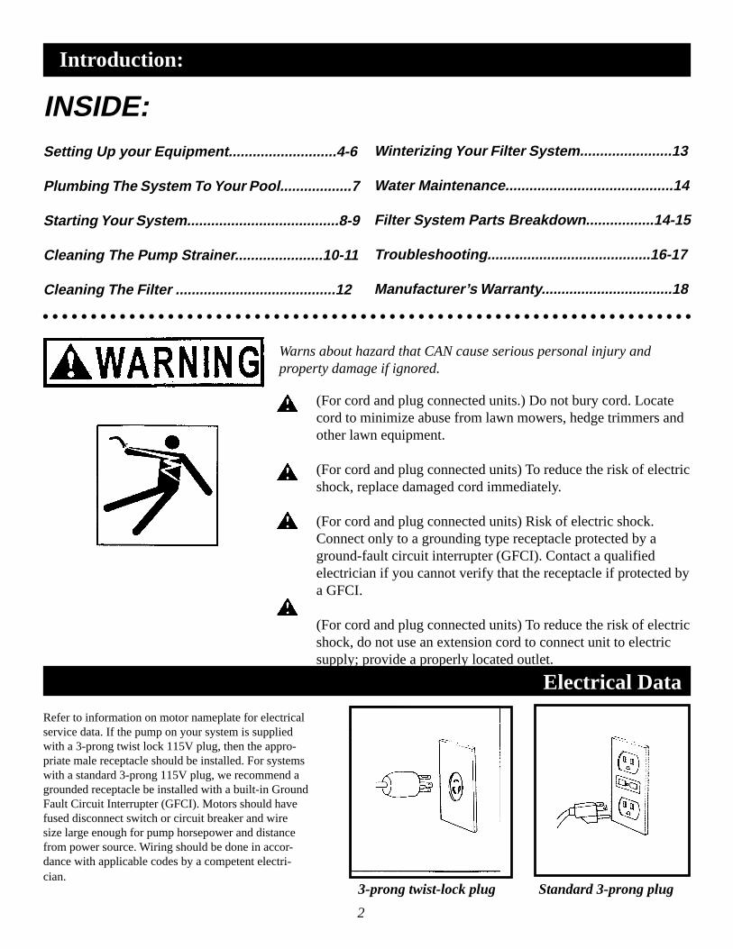
Warns about hazard that CAN cause serious personal injury andproperty damage if ignored.
(For cord and plug connected units.) Do not bury cord. Locatecord to minimize abuse from lawn mowers, hedge trimmers andother lawn equipment.
(For cord and plug connected units) To reduce the risk of electricshock, replace damaged cord immediately.
(For cord and plug connected units) Risk of electric shock.Connect only to a grounding type receptacle protected by aground-fault circuit interrupter (GFCI). Contact a qualifiedelectrician if you cannot verify that the receptacle if protected bya GFCI.
(For cord and plug connected units) To reduce the risk of electricshock, do not use an extension cord to connect unit to electricsupply; provide a properly located outlet.
2
Refer to information on motor nameplate for electricalservice data. If the pump on your system is suppliedwith a 3-prong twist lock 115V plug, then the appro-priate male receptacle should be installed. For systemswith a standard 3-prong 115V plug, we recommend agrounded receptacle be installed with a built-in GroundFault Circuit Interrupter (GFCI). Motors should havefused disconnect switch or circuit breaker and wiresize large enough for pump horsepower and distancefrom power source. Wiring should be done in accor-dance with applicable codes by a competent electri-cian.
Electrical Data
3-prong twist-lock plug Standard 3-prong plug
(a) (b) (c)
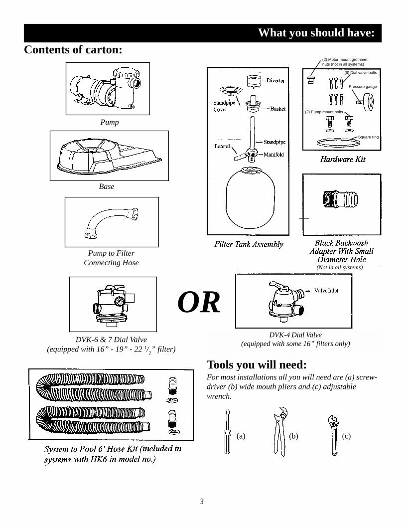
What you should have:Contents of carton:
Tools you will need:For most installations all you will need are (a) screw-driver (b) wide mouth pliers and (c) adjustablewrench.
3
Pump
Pump to FilterConnecting Hose
DVK-6 & 7 Dial Valve(equipped with 16” - 19” - 22 1/
2” filter)
OR
Base
(2) Motor mount grommetnuts (not in all systems)
(6) Dial valve bolts
Pressure gauge
(2) Pump mount bolts
Square ring
(Not in all systems)
DVK-4 Dial Valve(equipped with some 16” filters only)

Setting up your system:
4
Step 1Remove filter, pump and base from the carton.Using (2) 1/4 x 20 bolts and washers, mount pumpto base. The pump mounts using the jack nutsinstalled in the base. The pump should be posi-tioned such that the pump strainer is supported bythe system base.❖ Note: Some systems are supplied with push-ingrommet nuts for the pump mount. Install thesegrommets in the base using the pre-drilled holesnoted. (See Step 1A).
Step 1APush the grommet nuts into the pre-drilled holes inthe system base. Use the illustration at the right toensure the correct holes are used. Position theslots in the pump motor base over the grommetnuts and install the self-tapping screws to securethe pump to the base.
Setting up your system:
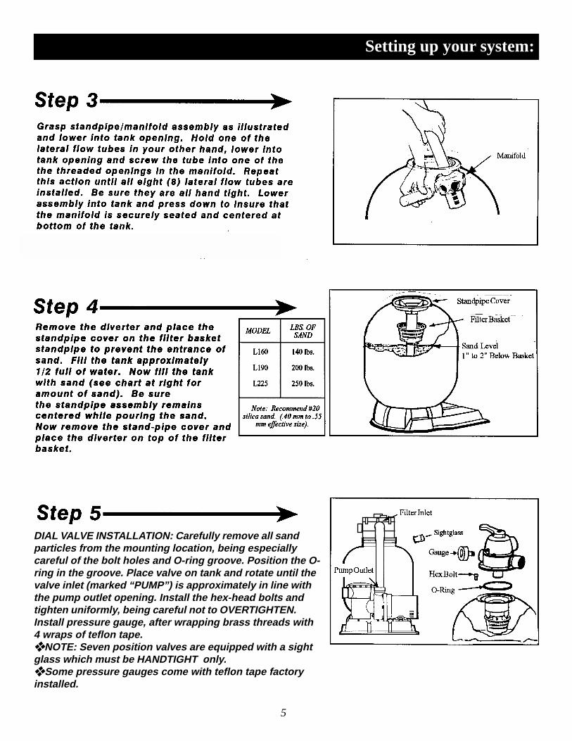
DIAL VALVE INSTALLATION: Carefully remove all sandparticles from the mounting location, being especiallycareful of the bolt holes and O-ring groove. Position the O-ring in the groove. Place valve on tank and rotate until thevalve inlet (marked “PUMP”) is approximately in line withthe pump outlet opening. Install the hex-head bolts andtighten uniformly, being careful not to OVERTIGHTEN.Install pressure gauge, after wrapping brass threads with4 wraps of teflon tape.❖ NOTE: Seven position valves are equipped with a sightglass which must be HANDTIGHT only.❖ Some pressure gauges come with teflon tape factoryinstalled.
5

Setting up your system:
Connect the pre-assembled plumbing connectionfrom the pump discharge to the valve inlet usingthe union nuts on either end of the flexible hose.IMPORTANT: Ensure the o-rings are in theadapter groove at each end of the hose. These o-rings were shipped installed at the factory andcould dislodge during transit.
❖ The adapter o-rings may be supplied in thesystem hardware kit.For 4-way valve: Install threaded adapter into thepump discharge, tighten handtight plus 1/2 turn.Now install the other adapter into the dial valveinlet, tighten in the same manner. Place one hoseclamp over each end of the pump to filter hose,push hose onto each adapter. Position the clampover barbed section of the adapter and tightenwith screw driver until snug.
6
If your system is supplied with a backwash adapter:Remove threaded adapter and tape from the hardwarekit. Prepare backwash fittings by wrapping threadswith teflon tape in a clockwise rotation, four to eightwraps is usually sufficient. Install adapter into thewaste port of the filter.
You are now ready to connect the system to your pool (see page 7)
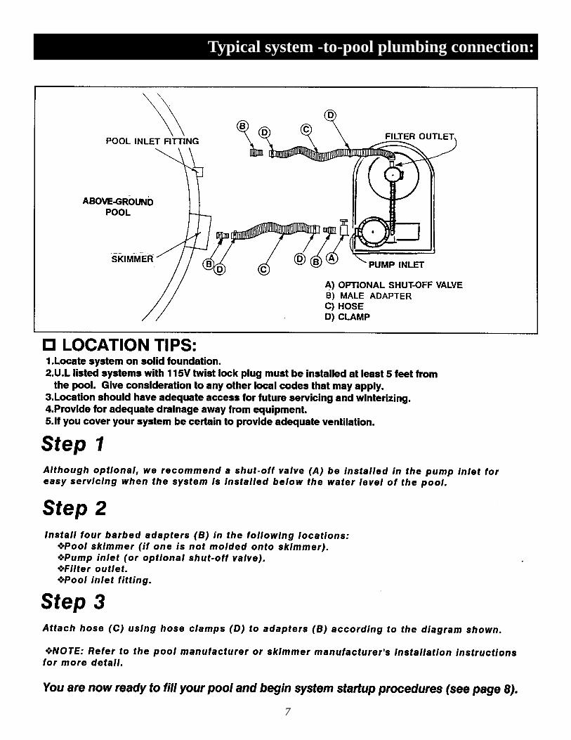
Typical system -to-pool plumbing connection:
7

8
System startup:

9
System startup:
1. Set dial valve to DRAIN position.
2. Start pump.
3. After flow has been established continue topump for 30 seconds.
4. Stop pump.
5. Set valve to BACKWASH position.
6. Start pump, run for one minute, (this action willclean and level the sand bed).
7. Stop pump.
8. Set valve to RINSE position,run for 30 seconds. Stop pump.( 7 position valve only)
9. Set valve to FILTER position.
10. Start pump - you are now in the first filtration cycle and yoursystem is filtering your pool.
step 3.
10
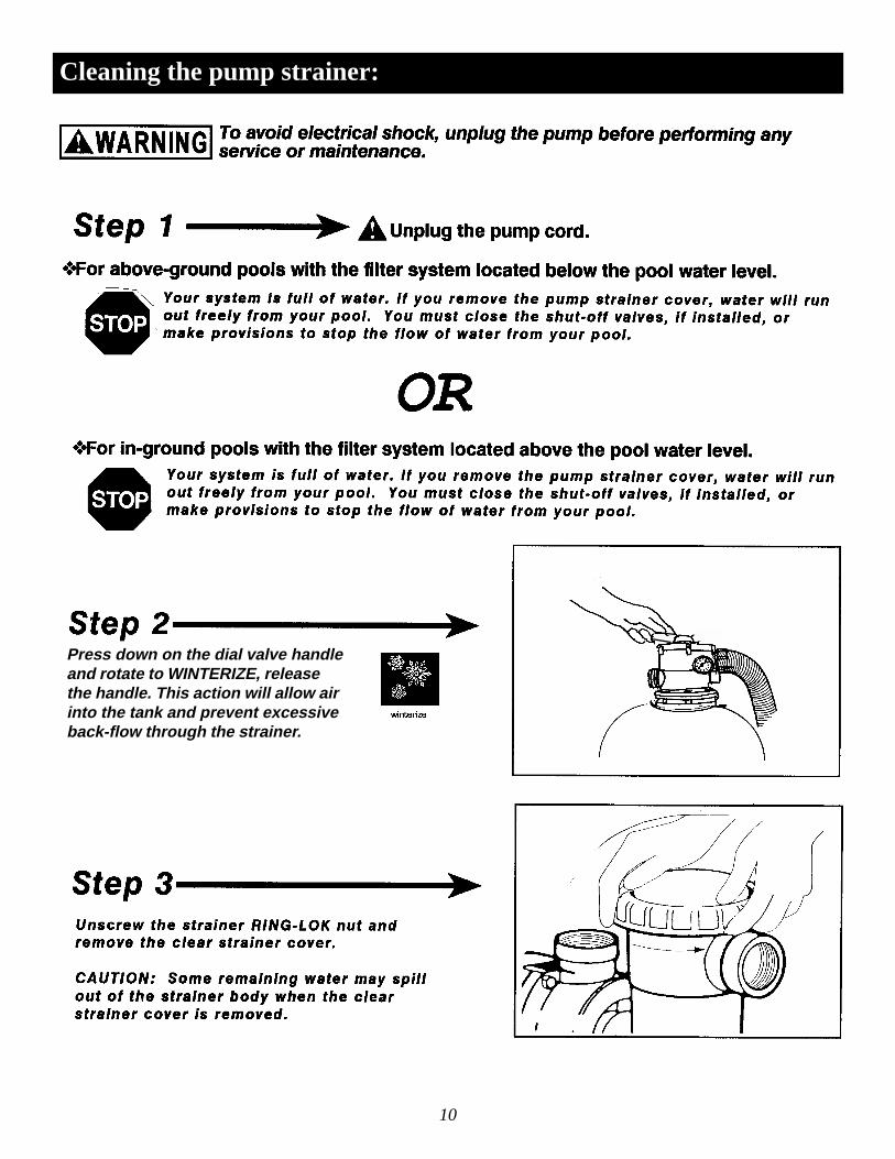
Press down on the dial valve handleand rotate to WINTERIZE, releasethe handle. This action will allow airinto the tank and prevent excessiveback-flow through the strainer.
Cleaning the pump strainer:

11
Cleaning the pump strainer:

Backwashing (cleaning) the filter:
1. Set dial valve to BACKWASH.
2. Start pump.
3. Observe water flow in sight glass andwhen clear (usually 2-3 minutes)stop pump.
4. Set valve to RINSE, run for 20-30seconds. This action removes anydebris trapped in the filter duringbackwash. (7 position valve only).
5. Stop pump.
6. Set valve to FILTER.
7. Start pump, you have now resumedfiltering your pool.
12

Winterizing the filter system:
13
Drain the filter tank by first removing thedrain and then set dial valve to WINTERIZE.Replace the drain cap once filter is drained.
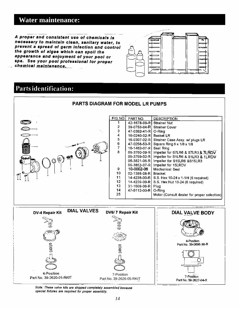
Water maintenance:
14
7-PositionPart No. 39-2626-05-RKIT
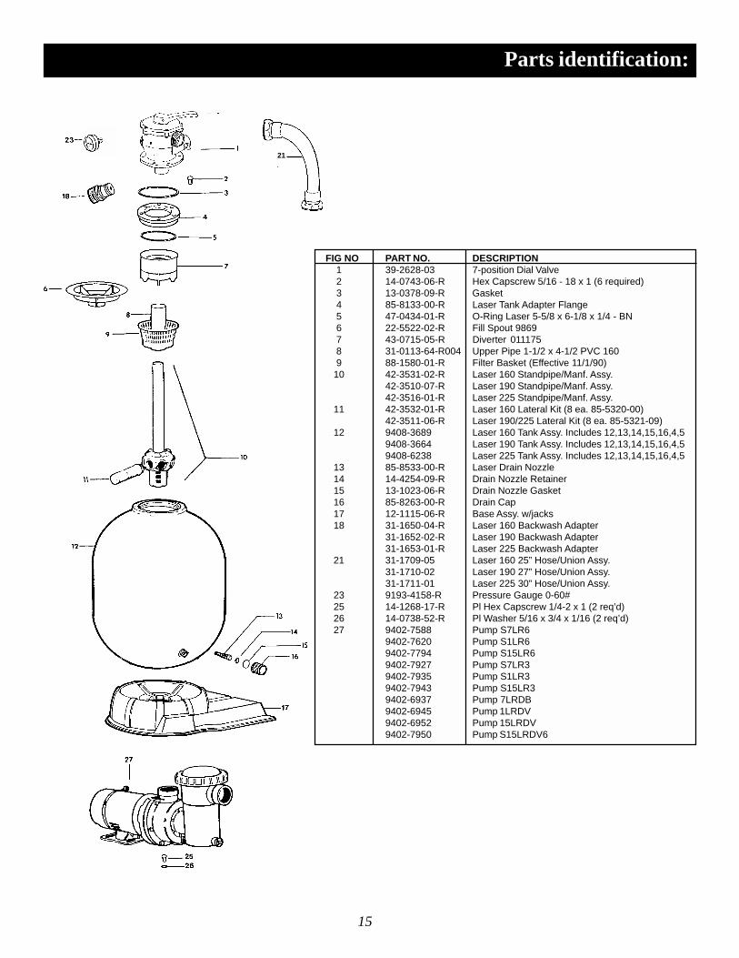
Parts identification:
21
FIG NO PART NO. DESCRIPTION 1 39-2628-03 7-position Dial Valve 2 14-0743-06-R Hex Capscrew 5/16 - 18 x 1 (6 required) 3 13-0378-09-R Gasket 4 85-8133-00-R Laser Tank Adapter Flange 5 47-0434-01-R O-Ring Laser 5-5/8 x 6-1/8 x 1/4 - BN 6 22-5522-02-R Fill Spout 9869 7 43-0715-05-R Diverter 011175 8 31-0113-64-R004 Upper Pipe 1-1/2 x 4-1/2 PVC 160 9 88-1580-01-R Filter Basket (Effective 11/1/90) 10 42-3531-02-R Laser 160 Standpipe/Manf. Assy.
42-3510-07-R Laser 190 Standpipe/Manf. Assy.42-3516-01-R Laser 225 Standpipe/Manf. Assy.
11 42-3532-01-R Laser 160 Lateral Kit (8 ea. 85-5320-00)42-3511-06-R Laser 190/225 Lateral Kit (8 ea. 85-5321-09)
12 9408-3689 Laser 160 Tank Assy. Includes 12,13,14,15,16,4,59408-3664 Laser 190 Tank Assy. Includes 12,13,14,15,16,4,59408-6238 Laser 225 Tank Assy. Includes 12,13,14,15,16,4,5
13 85-8533-00-R Laser Drain Nozzle 14 14-4254-09-R Drain Nozzle Retainer 15 13-1023-06-R Drain Nozzle Gasket 16 85-8263-00-R Drain Cap 17 12-1115-06-R Base Assy. w/jacks 18 31-1650-04-R Laser 160 Backwash Adapter
31-1652-02-R Laser 190 Backwash Adapter31-1653-01-R Laser 225 Backwash Adapter
21 31-1709-05 Laser 160 25” Hose/Union Assy.31-1710-02 Laser 190 27” Hose/Union Assy.31-1711-01 Laser 225 30” Hose/Union Assy.
23 9193-4158-R Pressure Gauge 0-60# 25 14-1268-17-R Pl Hex Capscrew 1/4-2 x 1 (2 req’d) 26 14-0738-52-R Pl Washer 5/16 x 3/4 x 1/16 (2 req’d) 27 9402-7588 Pump S7LR6
9402-7620 Pump S1LR69402-7794 Pump S15LR69402-7927 Pump S7LR39402-7935 Pump S1LR39402-7943 Pump S15LR39402-6937 Pump 7LRDB9402-6945 Pump 1LRDV9402-6952 Pump 15LRDV9402-7950 Pump S15LRDV6
15
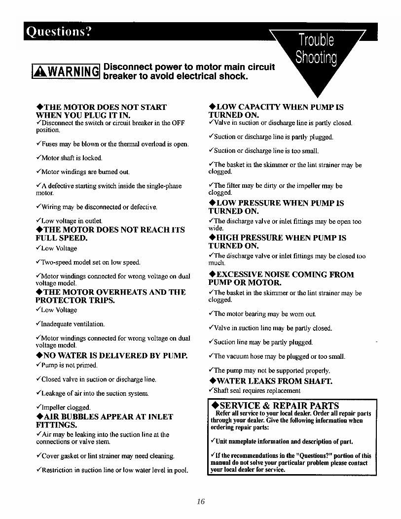
16

17

LIMITED WARRANTY
Jacuzzi Bros. Division (JBD) warrants its new products to be free from defects in workmanship and material for a period of 1year from the date of initial installation or 3 years from date of manufacture, whichever comes first. Laser and ST filter tanks arewarranted to be free of defects in material and workmanship for a period of 5 years from date of installation or 6 years from date ofmanufacture, whichever comes first. This warranty excludes damage or failure caused by freezing. Internal filter components andvalves are warranted to be free of defects in material and workmanship for 1 year from date of installation.
JBD’s warranty obligation with regard to equipment not of its own manufacture is limited to the warranty actually extendedto JBD by its supplier. Performance of equipment is further warranted to be in accordance with stated ratings when properly installedunder normal conditions of operation.
This warranty extends only to the original retail purchaser and only during the time in which the original retail purchaseroccupies the site where the product was originally installed.
Requests for service under this warranty shall be made by contacting the installing JBD dealer (point of purchase) as soon aspossible after the discovery of any alleged defect. JBD will subsequently take corrective action as promptly as reasonably possible.
JBD at its discretion may replace or repair any product that fails under this warranty after inspection by an authorizedcompany representative or after JBD has received the product at our factory. Replacement or repair cannot be made until after theproduct is inspected. All charges or expenses for freight to and from the factory, removal and reinstallation of the product, or installa-tion of a replacement product are the responsibility of the purchaser.
THIS WARRANTY SUPERSEDES ANY WARRANTY NOT DATED OR BEARING AN EARLIER DATE. ANYIMPLIED WARRANTIES WHICH THE PURCHASER MAY HAVE INCLUDING MERCHANTABILITY AND FITNESSFOR A PARTICULAR PURPOSE, SHALL NOT EXTEND BEYOND THE APPLICABLE WARRANTY PERIOD. Somestates do not allow limitations on how long an implied warranty lasts so the above limitation may not apply to you. IN NOEVENT SHALL JBD BE LIABLE FOR INCIDENTAL OR CONSEQUENTIAL DAMAGES. Some states do not allow theexclusion or limitation of incidental or consequential damages, so the above may not apply to you.
This warranty does not apply to any product which has been subjected to negligence, alteration, accident, abuse, misuse,improper installation, vandalism, civil disturbances, or acts of God. The only warranties authorized by JBD are those set forth herein.JBD does not authorize other persons to extend any warranties with respect to its products, nor will JBD assume liability for anyunauthorized warranties made in connection with the sale of its products.
THIS WARRANTY GIVES YOU SPECIFIC LEGAL RIGHTS, AND YOU MAY ALSO HAVE OTHER RIGHTSWHICH MAY VARY FROM STATE TO STATE.
Manufacturer’s warranty:
18

19

12401 Interstate 30 P.O. Box 8903 Little Rock, AR 72219-8903 Telephone: (501) 455-1234