Embed Size (px)
Citation preview
1
Software and Services
Since 1976
LASER SCANNING TECHNOLOGY IN SUPPORT OF
NUCLEAR PLANT LIFECYCLE
PREPARED FOR HMIT CONFERENCE
Amadeus Burger
CSA, Inc.
450 Franklin Road, Suite 130
Marietta, Georgia 30067
ABSTRACT
Laser scanning technology provides a high quality, accurate 3D as-built representation of
a nuclear power plant. This paper describes the technology and its applications for several
activities related to the nuclear plant lifecycle support. The applications include equipment
removal/ replacement, plant outage support, power uprate support, ALARA applications, and
others. The biggest benefits are reduction of time associated with plant activities and dose
reduction.
1 INTRODUCTION
This paper will provide a description of laser scanning technology used in support of
lifecycle activities of the nuclear power industry.
1.1 Laser Scanning
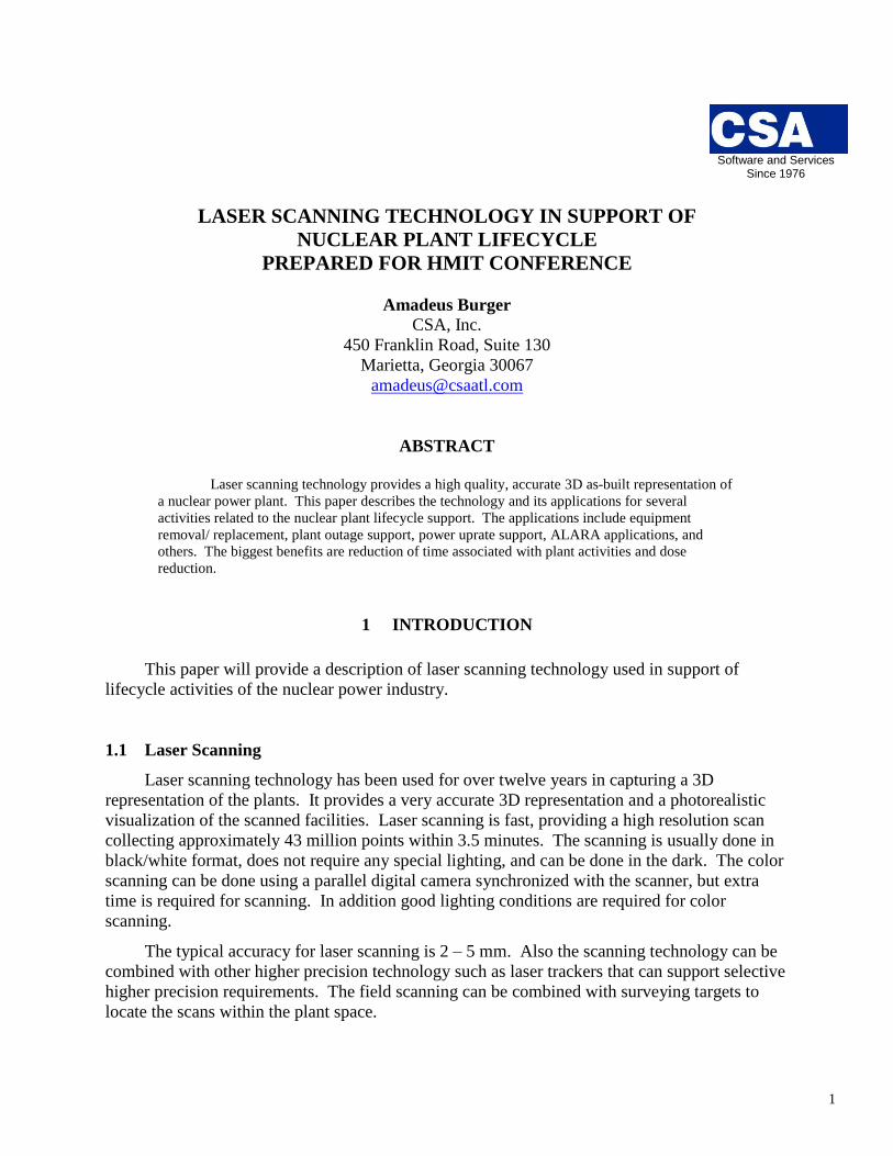
Laser scanning technology has been used for over twelve years in capturing a 3D
representation of the plants. It provides a very accurate 3D representation and a photorealistic
visualization of the scanned facilities. Laser scanning is fast, providing a high resolution scan
collecting approximately 43 million points within 3.5 minutes. The scanning is usually done in
black/white format, does not require any special lighting, and can be done in the dark. The color
scanning can be done using a parallel digital camera synchronized with the scanner, but extra
time is required for scanning. In addition good lighting conditions are required for color
scanning.
The typical accuracy for laser scanning is 2 – 5 mm. Also the scanning technology can be
combined with other higher precision technology such as laser trackers that can support selective
higher precision requirements. The field scanning can be combined with surveying targets to
locate the scans within the plant space.
2
Figure 1. Photorealistic view of laser scan.
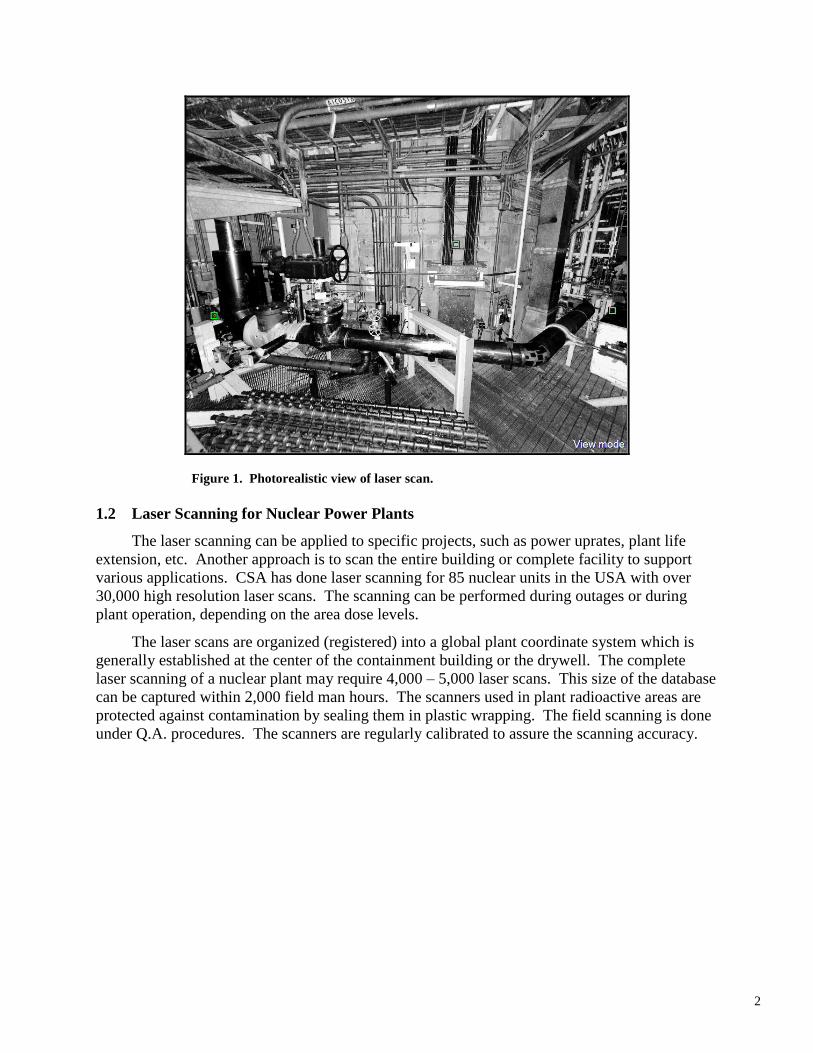
1.2 Laser Scanning for Nuclear Power Plants
The laser scanning can be applied to specific projects, such as power uprates, plant life
extension, etc. Another approach is to scan the entire building or complete facility to support
various applications. CSA has done laser scanning for 85 nuclear units in the USA with over
30,000 high resolution laser scans. The scanning can be performed during outages or during
plant operation, depending on the area dose levels.
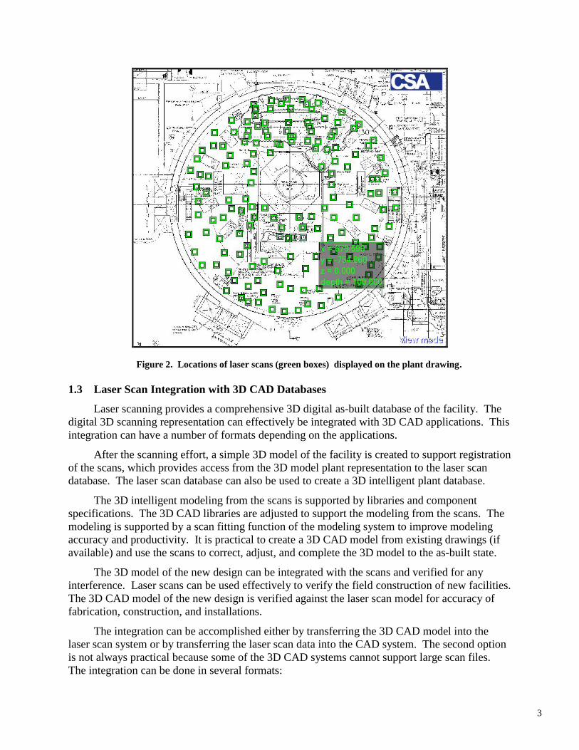
The laser scans are organized (registered) into a global plant coordinate system which is
generally established at the center of the containment building or the drywell. The complete
laser scanning of a nuclear plant may require 4,000 – 5,000 laser scans. This size of the database
can be captured within 2,000 field man hours. The scanners used in plant radioactive areas are
protected against contamination by sealing them in plastic wrapping. The field scanning is done
under Q.A. procedures. The scanners are regularly calibrated to assure the scanning accuracy.
3
Figure 2. Locations of laser scans (green boxes) displayed on the plant drawing.
1.3 Laser Scan Integration with 3D CAD Databases
Laser scanning provides a comprehensive 3D digital as-built database of the facility. The
digital 3D scanning representation can effectively be integrated with 3D CAD applications. This
integration can have a number of formats depending on the applications.
After the scanning effort, a simple 3D model of the facility is created to support registration
of the scans, which provides access from the 3D model plant representation to the laser scan
database. The laser scan database can also be used to create a 3D intelligent plant database.
The 3D intelligent modeling from the scans is supported by libraries and component
specifications. The 3D CAD libraries are adjusted to support the modeling from the scans. The
modeling is supported by a scan fitting function of the modeling system to improve modeling
accuracy and productivity. It is practical to create a 3D CAD model from existing drawings (if
available) and use the scans to correct, adjust, and complete the 3D model to the as-built state.
The 3D model of the new design can be integrated with the scans and verified for any
interference. Laser scans can be used effectively to verify the field construction of new facilities.
The 3D CAD model of the new design is verified against the laser scan model for accuracy of
fabrication, construction, and installations.
The integration can be accomplished either by transferring the 3D CAD model into the
laser scan system or by transferring the laser scan data into the CAD system. The second option
is not always practical because some of the 3D CAD systems cannot support large scan files.
The integration can be done in several formats:
4
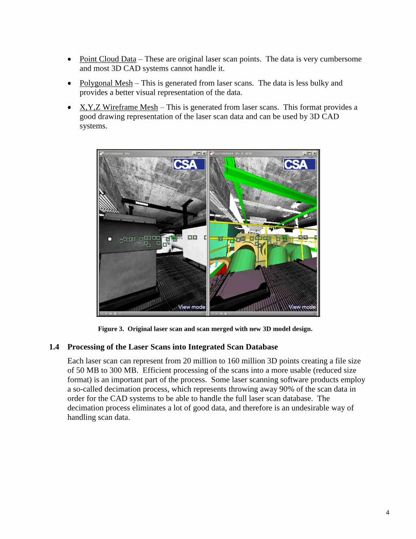
Point Cloud Data – These are original laser scan points. The data is very cumbersome
and most 3D CAD systems cannot handle it.
Polygonal Mesh – This is generated from laser scans. The data is less bulky and
provides a better visual representation of the data.
X,Y,Z Wireframe Mesh – This is generated from laser scans. This format provides a
good drawing representation of the laser scan data and can be used by 3D CAD
systems.
Figure 3. Original laser scan and scan merged with new 3D model design.
1.4 Processing of the Laser Scans into Integrated Scan Database
Each laser scan can represent from 20 million to 160 million 3D points creating a file size
of 50 MB to 300 MB. Efficient processing of the scans into a more usable (reduced size
format) is an important part of the process. Some laser scanning software products employ
a so-called decimation process, which represents throwing away 90% of the scan data in
order for the CAD systems to be able to handle the full laser scan database. The
decimation process eliminates a lot of good data, and therefore is an undesirable way of
handling scan data.
5
More practical formats are:
3D Panoramic Bitmap – It provides high quality visualization of the scans.
High Quality 3D CAD Mesh – It optimizes polygonal surface CAD representation
generated from laser scans.
3D Edge Representation – It is created from the polygonal mesh.
X,Y,Z Wireframe – It is created from the scans.
Hybrid Model – It is a combination of 3D CAD model and point cloud data.
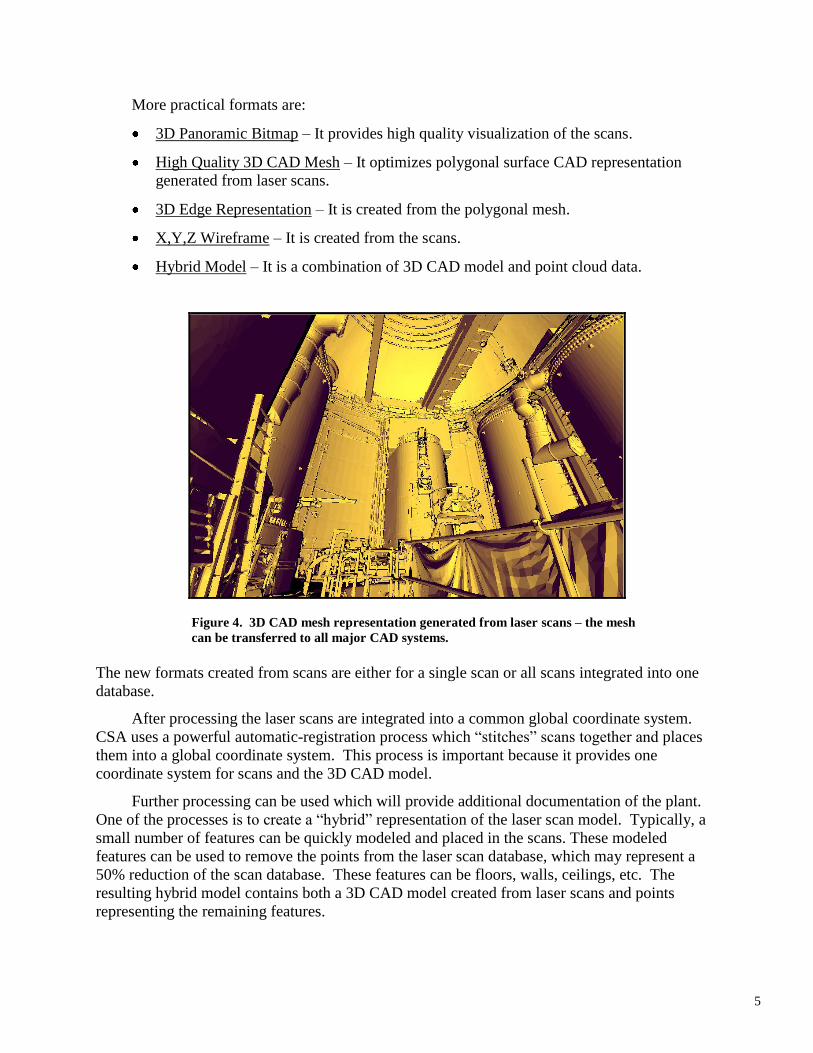
Figure 4. 3D CAD mesh representation generated from laser scans – the mesh
can be transferred to all major CAD systems.
The new formats created from scans are either for a single scan or all scans integrated into one
database.
After processing the laser scans are integrated into a common global coordinate system.
CSA uses a powerful automatic-registration process which “stitches” scans together and places
them into a global coordinate system. This process is important because it provides one
coordinate system for scans and the 3D CAD model.
Further processing can be used which will provide additional documentation of the plant.
One of the processes is to create a “hybrid” representation of the laser scan model. Typically, a
small number of features can be quickly modeled and placed in the scans. These modeled
features can be used to remove the points from the laser scan database, which may represent a
50% reduction of the scan database. These features can be floors, walls, ceilings, etc. The
resulting hybrid model contains both a 3D CAD model created from laser scans and points
representing the remaining features.
6
The plant’s laser scans are placed into an integrated 3D plant master scan database – there
is no limit to the number of scans within the database. Once the database is created, the user can
access any set of scans in the database.
1.5 User Access to the Laser Scan Plant Configuration
The user is provided with a high-quality photorealistic representation which gives access to
the overall plant configuration. The access is provided by organizing the plant into buildings,
floors, and other areas. The user has available several formats by which the access to the areas
can be done, with no scan number limitation. One of the largest scanning projects CSA has
performed contains over 7,000 laser scans representing a single nuclear site with two units.
Another way to organize the data is by individual projects for which the scanning was used,
such as equipment removal/replacement, verification of design for plant design changes, special
studies, etc. Frequently the database contains several versions of scanning, representing laser
scanning before equipment removal/replacement and after completion of the replacement
project.
The individual scan projects are added to the single plant master database. A properly
organized project structure provides the user access to any part of the plant within four to five
clicks. The access is provided through a set of keyplan drawings representing individual plant
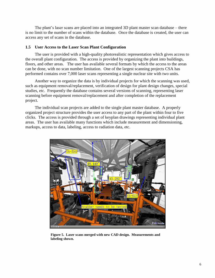
areas. The user has available many functions which include measurement and dimensioning,
markups, access to data, labeling, access to radiation data, etc.
Figure 5. Laser scans merged with new CAD design. Measurements and
labeling shown.
7
1.6 Configuration Management of the Laser Scan Plant Database
Quality control is used during all phases of the creation and maintenance of the laser scan
plant configuration. The most important phase is the first one, field work, which includes
verification of scanner calibration, proper location of scans, creation of field scan register, target
placement, and surveying of targets. The field scan register contains the detail record for each
scan.
The second phase, scan processing and registration, is to create or update the scan database.
The steps in this phase control the processing of the laser scans, verification of scan registration,
and creation or update of the laser scan master database. The configuration control of these
activities is similar to the configuration control of design drawings and the scan file is similar to
the drawing file. The change control and revision control can be managed by PLM systems,
such as Siemens PLM System. This is beneficial, especially if the PLM system is also used to
manage associated CAD files and related documents.
1.7 Use of a Comprehensive Laser Scan Configuration Database
The user is provided with a powerful 3D viewer - PanoMap® which provides a panoramic
view with access to the spatial database in a photorealistic format. Through PanoMap® the user
can access several functions and applications. This includes:
Measurements – The measurements are available in a number of forms – vertical,
horizontal, true distance, from scan background to new design, etc. The typical
accuracy is within 0.2”. The dimensions can be placed against the scans.
Creation of Labels – Labels can be created and placed in the laser scans. Individual
components can be identified by labels and linked to plant maintenance systems, such
as Maximo and PassPort. A tie to drawings, P&IDs, and photographs can be
established through labels.
Interface to CAD – To/from export is available to major CAD systems. The CAD data
can be used for many applications, such as interference checking, visualization,
interface to schedule (storyboarding), etc.
Creation of CAD objects – Multiple 3D modeling functions are available, including
automatic detection of cylinders, elbows, and plans. Modeling is supported with an
extensive 3D CAD parametric library of components. The systems provides automatic
component fitting functions.
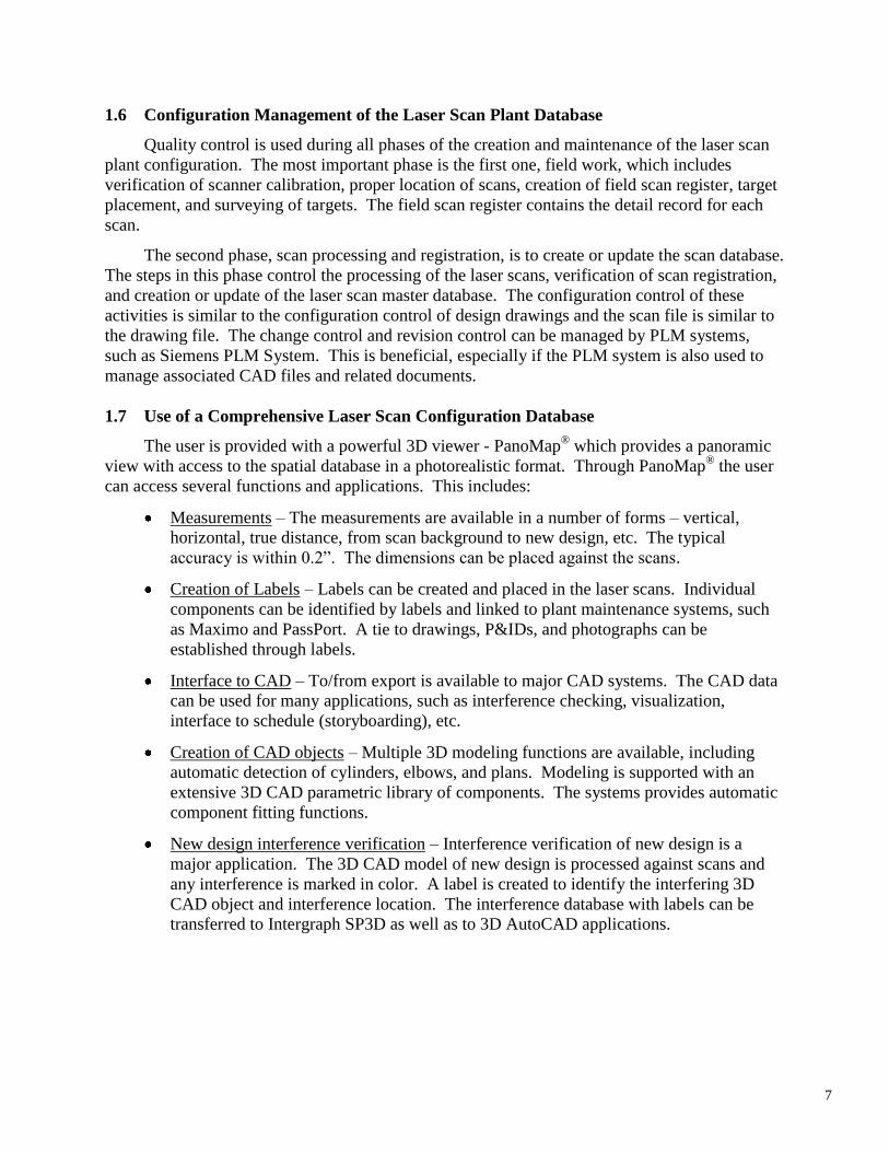
New design interference verification – Interference verification of new design is a
major application. The 3D CAD model of new design is processed against scans and
any interference is marked in color. A label is created to identify the interfering 3D
CAD object and interference location. The interference database with labels can be
transferred to Intergraph SP3D as well as to 3D AutoCAD applications.
8
Figure 6. New design verified against laser scans. Interferences shown in red.
Creation of drawings – Orthographic drawings can be created from the laser scan
database. The drawing generator can create drawings in bitmap format for any selected
area. All scans within the selected area are used for drawing processing. The drawing
is provided in full scale and can be transferred to AutoCAD or MicroStation.
Verification of new design – A new design created in 3D CAD format can be imported
into the scan database to be visually reviewed and verified for any interference.
Creation of training instructions – A laser scan representation provides a high quality
visual representation of plant areas. The laser scans, which contain applicable markups
with narrative, can provide a very effective tool for training purposes. The same
database can be used to collect “tribal knowledge” which can be placed on object labels
for placement in scans.
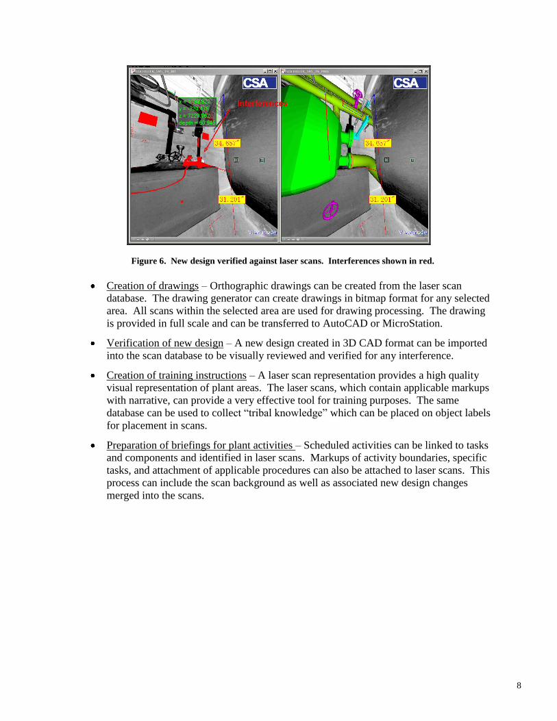
Preparation of briefings for plant activities – Scheduled activities can be linked to tasks
and components and identified in laser scans. Markups of activity boundaries, specific
tasks, and attachment of applicable procedures can also be attached to laser scans. This
process can include the scan background as well as associated new design changes
merged into the scans.
9
Figure 7. Project schedule is integrated with laser scans and construction
schedule storyboard is produced.
1.8 Typical Applications of the Laser Scan Spatial Database
The laser scan database is being used for many applications in support of plant lifecycle
activities, including:
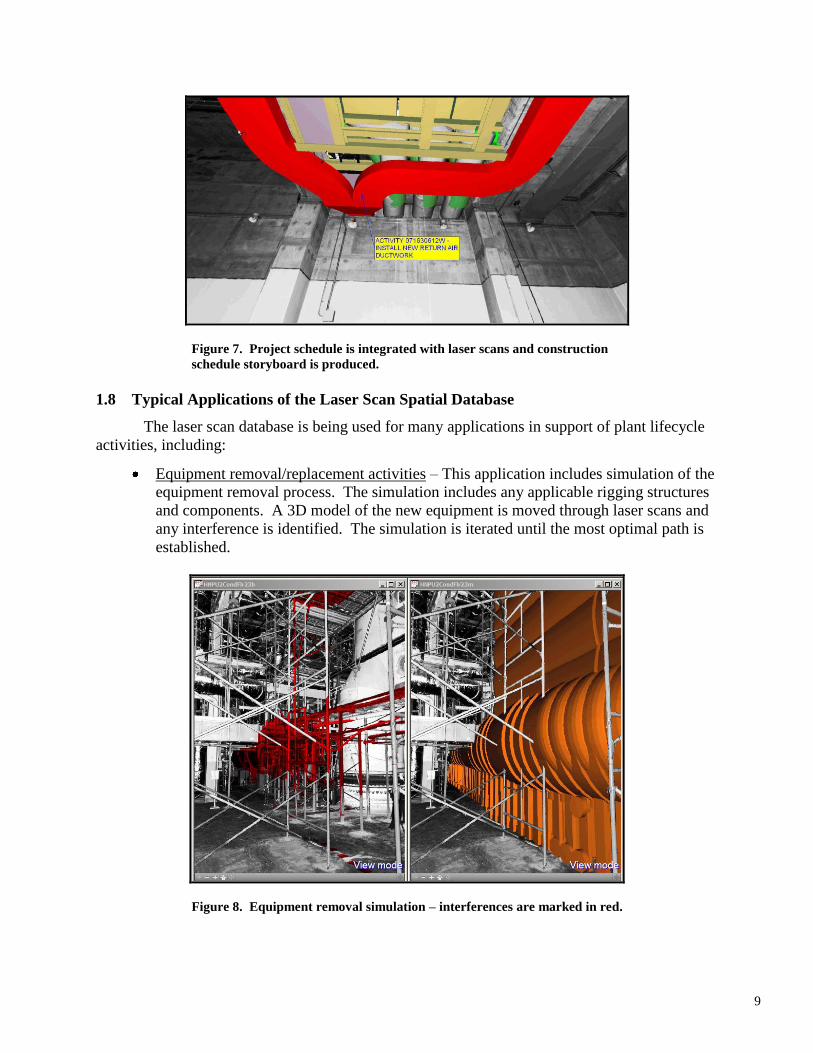
Equipment removal/replacement activities – This application includes simulation of the
equipment removal process. The simulation includes any applicable rigging structures
and components. A 3D model of the new equipment is moved through laser scans and
any interference is identified. The simulation is iterated until the most optimal path is
established.
Figure 8. Equipment removal simulation – interferences are marked in red.
10
EPUs – Power uprate activities include equipment removal/replacement, plant
modifications and changes, inspections, and special plant review analysis. These
activities can be supported by laser scanning for planning, design changes, construction
support, briefing and training of people, and other activities.
Plant life extension applications – Plant life extension activities can also benefit from
laser scanning and have similar activities to the EPUs.
Outage support planning – Plant outage support includes the planning effort, support of
plant modifications, planning of ISI inspections, and scaffolding design. Dose
reduction initiative can be well supported by use of the laser scanning database.
Design of radiation shielding structures – Radiation shielding structures are placed in
congested high-dose areas. Laser scanning provides a very effective tool to plant,
design, and implement the radiation support structures in these areas by identifying any
interference.
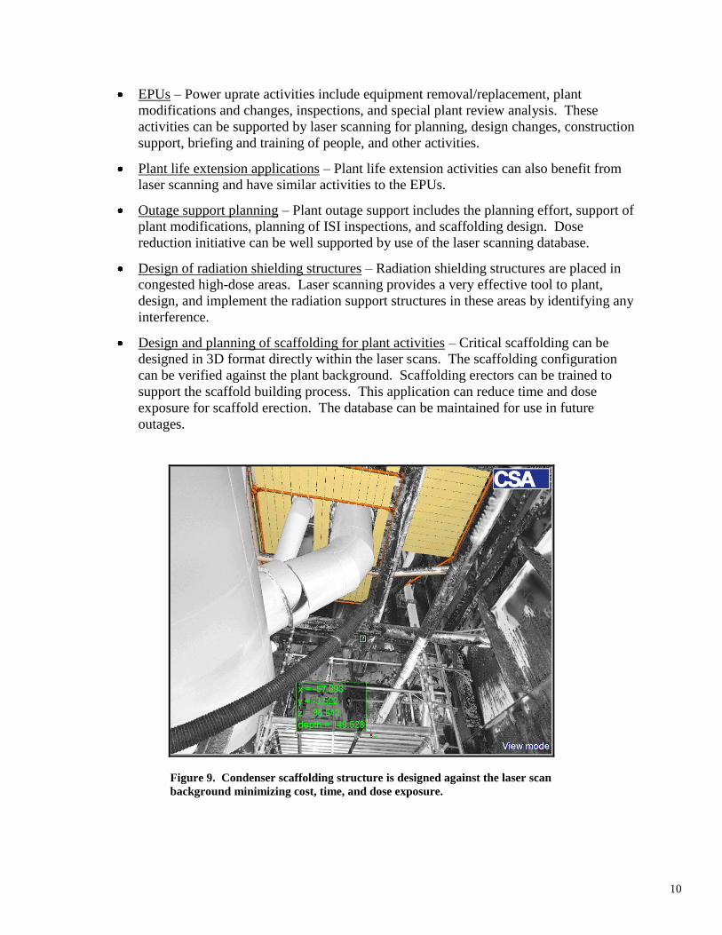
Design and planning of scaffolding for plant activities – Critical scaffolding can be
designed in 3D format directly within the laser scans. The scaffolding configuration
can be verified against the plant background. Scaffolding erectors can be trained to
support the scaffold building process. This application can reduce time and dose
exposure for scaffold erection. The database can be maintained for use in future
outages.
Figure 9. Condenser scaffolding structure is designed against the laser scan
background minimizing cost, time, and dose exposure.
11
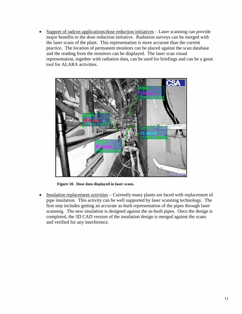
Support of radcon applications/dose reduction initiatives – Laser scanning can provide
major benefits to the dose reduction initiative. Radiation surveys can be merged with
the laser scans of the plant. This representation is more accurate than the current
practice. The location of permanent monitors can be placed against the scan database
and the reading from the monitors can be displayed. The laser scan visual
representation, together with radiation data, can be used for briefings and can be a great
tool for ALARA activities.
Figure 10. Dose data displayed in laser scans.
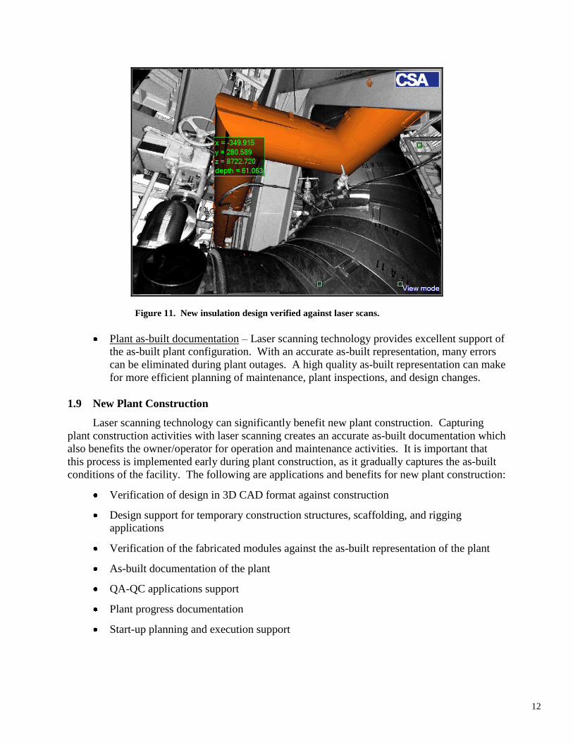
Insulation replacement activities – Currently many plants are faced with replacement of
pipe insulation. This activity can be well supported by laser scanning technology. The
first step includes getting an accurate as-built representation of the pipes through laser
scanning. The new insulation is designed against the as-built pipes. Once the design is
completed, the 3D CAD version of the insulation design is merged against the scans
and verified for any interference.
12
Figure 11. New insulation design verified against laser scans.
Plant as-built documentation – Laser scanning technology provides excellent support of
the as-built plant configuration. With an accurate as-built representation, many errors
can be eliminated during plant outages. A high quality as-built representation can make
for more efficient planning of maintenance, plant inspections, and design changes.
1.9 New Plant Construction
Laser scanning technology can significantly benefit new plant construction. Capturing
plant construction activities with laser scanning creates an accurate as-built documentation which
also benefits the owner/operator for operation and maintenance activities. It is important that
this process is implemented early during plant construction, as it gradually captures the as-built
conditions of the facility. The following are applications and benefits for new plant construction:
Verification of design in 3D CAD format against construction
Design support for temporary construction structures, scaffolding, and rigging
applications
Verification of the fabricated modules against the as-built representation of the plant
As-built documentation of the plant
QA-QC applications support
Plant progress documentation
Start-up planning and execution support
13
2 CONCLUSION
Laser scanning technology, combined with intelligent 3D CAD models, is a proven mature
technology which can provide major benefits for lifecycle management of nuclear facilities. The
implementation can start with specific projects, such as equipment replacement or permanent
shielding design, and gradually lead to comprehensive plant documentation. For successful use
of this technology, it is essential to make the technology available to as many users as possible at
the plant location.