Embed Size (px)
Citation preview

3
Laser Welding of Aluminum Alloys K. H. Leonga, K. R. Saboa, P. G. Sandersa, W. J. Spawrb
aTechnology Development Division, Argonne National Laboratory bSpawr Industries
ABSTRACT
Recent interest in reducing the weight of automobiles to increase fuel mileage has focussed attention on the use of aluminum and associated joining technologies. Laser beam welding is one of the more promising methods for high speed welding of aluminum. Consequently, substantial effort has been expended in attempting to develop a robust laser beam welding process. Early results have not been very consistent in the process requirements but more definitive data has been produced recently. This paper reviews the process parameters needed to obtain consistent laser welds on 5000 series aluminum alloys and discusses the research necessary to make laser processing of aluminum a reality for automotive applications.
Keywords: laser beam welding, aluminum, weld parameters
INTRODUCTION
Laser processing offers an inertialess tool for high speed precision cutting, welding, drilling, heat treating and cladding. 1 The inertialess laser beam can cut with minimal distortion. Laser welding produces narrow weld beads and low distortion compared to conventional arc welding. Laser beams can cut or weld sheet metal with speeds exceeding 10 mfmin. Consequently, laser processing is ideal for the high speed manufacturing required in the automotive industry:
Laser processing of steels is well established in the automotive industry.2 Recent interests have focused on laser welding lightweight aluminum alloys. The attraction of lightweight metals is in the high strength to weight ratio and the consequential improvement in mileage. Several methods are available for joining aluminum. They include the use of adhesives, welding and riveting techniques. Laser beam welding has been identified by industry as one of the more promising techniques because of its high speed and low distortion. Initial attempts to laser weld aluminum has not been very successful because of the lack of understanding of process requirements. The high reflectivity and thermal conductivity of aluminum require much higher laser beam irradiances than for steel.
The current understanding of threshold laser beam irradiance requirements has allowed consistent welds to be obtained. The Advanced Research Laboratory at Pennsylvania State University, Ohio State University Welding Engineering, Fraunhoffer Resource Center, University of Illinois-UC Center for Laser Aided Materials Processing, University of Tennessee Space Institute and others have researched the laser beam welding of aluminum. Argonne and Sandia National Laboratories have also laser welded aluminum alloys. The results obtained by different groups have been rather inconsistent with respect to the performance of different lasers, edge preparation of the workpiece and the process parameters. The important question of whether laser beam welds can meet the materials properties necessary for automotive applications particularly in blank welding is still undetermined.
Argonne has initiated a fundamental and integrated approach to the laser welding of aluminum to resolve the processing
p ! $ ~ ; ~ ' , , r ~ ~ ~ ~ , ~ 2:;s ~~~~~~~~~~ 1s U ~ ~ [ ~ I T ~ D 'E-mail: Keng-Leong@qmgate,anl.gov, WWW:http://www.td.anI.gov/LALweb.htl, Te. (630) 252-3254. FAX (630)

DISCLAIMER
This report was prepared as an account of work sponsored by an agency of the United States Government. Neither the United States Government nor any agency thereof, nor any of their employees, make any warranty, express or implied, or assumes any legal liabili- ty or responsibility for the accuracy, completeness, or usefulness of any information, appa- ratus, product, or process disclosed, or represents that its use would not infringe privately owned rights. Reference herein to any specific commercial product, process, or service by trade name, trademark, manufacturer, or otherwise does not necessarily constitute or imply its endorsement, recommendation, or favoring by the United States Government or any agency thereof. The views and opinions of authors expressed herein do not necessar- ily state or reflect those of the United States Government or any agency thereof.

Portions of this document m y be illegible in electronic image products. Images are produced from the best available original dOl.umeIlt

inconsistencies and to determine the applicability of laser beam welding for automotive applications. The approach includes collaboration with laser (U.S. Laser) and beam delivery (Laser Mechanisms, Spawr Industries) manufacturers as well as manufacturers (Alcan International Limited, Reynolds Metals Company) and users of aluminum alloys (USCAR Low Emissions Partnership). The research and development effort encompasses the following:
1.
2.
3.
delivery of a laser beam with the required irradiance to the workpiece,
development of a cross flow system to prevent spatter on the optics for reduced maintenance and trouble free operation,
development of the process parameters to meet materials properties requirements, and
4. development of a simple, rugged and low-cost weld monitor suitable for quality assurance in the factory environment.
BEAM PARAMETER REQUIREMENTS
Recent work has examined beam irradiance requirements for the laser welding of aluminum alloys.3-7 In terms of energy balance, a high energy and irradiance laser beam interacting with an aluminum surface has to transfer sufficient energy to affect a weld. This requirement imposes a beam irradiance threshold for a particular alloy, where the energy absorbed is sufficient to melt the metal, allowing for the heat loss through conduction into the surrounding metal. A conservation of energy analysis shows that the parameters affecting the threshold irradiance includes the absorptivity of the surface, thermal conductivity and diffusivity of the alloy, heat required to bring the alloy to the melting point, heat of melting, beam diameter and travel speed of the beam. The joint configuration will also have an effect because trapping of the beam will enhance absorption.8
For steel, the absorptivity for C 0 2 beams is approximately 10% (depending on the condition of the surface) and the thermal conductivity is approximately 22 W/m-K.9 Beam irradiance thresholds obtained are 406 W cm-2. For aluminum, the corresponding values are approximately 5% and 200 W/m-K. Consequently, higher irradiances are required to weld aluminum alloys. The threshold beam irradiances for 5000 series aluminum alloys are 0.8 to 3 x 10⁶ W cm-2 and 6000 series are 1 to 5 x 10⁶ W cm-2.3-7 The range of values reported is a consequence of the different beam size at the surface and the welding speed used. For the case of the shorter wavelength Nd:YAG beam, the absorptivities for both steel and aluminum are substantially higher (-40% at 1000K).1 The threshold irradiances for 5000 and 6000 series aluminum alloys reduces t,o e l x 106 W cm2 and <2x 10⁶ W cm-2 respectively.4-6
For a particular joint configuration, the required irradiance to produce consistent welds will be impacted by several variables. One factor mentioned above is the possibility of increased effective beam absorption from beam trapping within the gap between the components to be welded. This situation will allow for lower threshold irradiance or higher welding speed. Aluminum oxidizes readily and the presence of an oxide layer will increase the absorptivity.10 Joint fitup and surface absorption tend to vary form day to day or from one batch of components to another. These variations in absorptivities may result in inconsistent welds when the beam irradiance used is insufficient. Figure 1 shows the data obtained for attempted welds on alloy 5182 samples at different beam irradiance levels using a C 0 2 laser beam. The graph has three shaded regions: the white or unshaded area is where consistent welds are produced, the dark area is where inconsistent welds occurred and the lightly shaded area where no welds were produced. Above the threshold irradiance required for consistent welds (2.3 x lo6 w cm-2), consistent coupling of the laser beam is obtained. Below this threshold irradiance, good welds may be obtained one day and the beam may not couple or couple inconsistently the next day. Consequently, an adequate beam irradiance is required for consistent welds and to account for the variations in threshold irradiance caused by sample variations that are typical in production. However, too high a beam irradiance will lead to weld quality problems as discussed below.

1.ox106
5 . 0 ~ 1 0 ~
0.ox 100 2.3 3 3 .3 4 4 :5 5:5
Laser power (kilowatts) I
Figure 1 Mean irradiance of a near TEM 20 CO 2 laser beam used for attempted welds on 5182 aluminum plotted as a function of the beam power. The data include butt and bead on plate (BOP) welds. Uncoupled indicates that the beam only scribed the aluminum and did not produce a weld. Coupled means that a consistent weld of approximately 4 inches length was produced. Inconsistent means that along the 4 in length intermittent welds were produced.
SHIELDING GAS REQUIREMENTS
Inert gas shielding is normally applied during welding to prevent oxidation or degradation of the weld. Most h e r welding systems use a gas jet aimed at the laser beam spot on the metal surface. This gas jet is usually produced with a small (-0.25 in diameter) copper tube placed at a 30"-60" angle to the metal surface. This shielding gas configuration is a carryover from the usual practice for welding steel even though aluminum is more sensitive to oxidation effects. Moreover, tests carried out at Argonne showed that this shielding gas configuration tends to entrain ambient air and cause oxidation of the weld. Energy dispersive X-ray spectroscopy analysis of the surfaces of welded 5182 and 5754 alloys showed increases in oxygen content of 2-8 wt 96 compared to the base metal. The oxidation effect is visually evident when welding vanadium or titanium where the presence of oxidation (>100ppm) is indicated by a discolored weld surface compared to a shiny metallic oxide-free surface. It should be noted that with the use of a side-jet for shielding, a greyish black deposit of mostly magnesium is usually produced downstream of the jet. Use of a trailing edge jet (blowing along the weld opposite to the direction of weIding) resulted in a greyish color weld surface compared to the leading edge jet which yielded a shiny surface.
Compared to welding nozzles, side-jet shielding requires less rigorous alignment and maintenance. For improved inert gas shielding special nozzles are required. One configuration that is in use is the plasma torch type nozzle where the beam exits through a hole in the center coincident with shielding gas flow. In addition, a circular ring around the center hole provides additional shielding gas. The downward gas flow through the center hole and ring is forced radially outwards along the metal
i’
surface. This gas flow configuration avoids the entrainment effect of an asymmetric side-jet. For additional shielding at high weld speeds, the authors use a gas shielding shroud with initial downward inert gas flow and a longer shroud length trailing over the welded region. Fixturing flexibility is compromised to allow the shield gas shroud to travel over the weld.
Inert gas shielding of the weld underbead is necessary for through penetration welds in aluminum. This is usually accomplished using helium directed upward to the bottom of the weld. An improved method used by the authors is the use of a special fixturing base plate with a groove that is flooded with helium. The plates to be welded are placed on top of the groove and entrainment of ambient air is prevented with a constant flow of helium.
Helium is the preferred shield gas (although the most costly) because of its high ionization potential and thermal diffusivity.10 Mixtures of argon and helium have been used successfully but the use of helium alone tends to produce optimal coupling of the beam to the metal surface. . There is some confusion in the literature regarding the use of argon-helium mixtures and beam defocussing, i.e., the focal point of the beam is above the surface. It appears that when an irradiance substantially above the threshold value is used, instability of the weldpool occurs leading to void formation and cavity defects.5 This situation is remedied with the addition of argon to the helium shield gas. The effect is to either increase plasma formation (resulting in defocussing of the beam) or decrease the coupling of the beam energy to the surface resulting in an increase in weldpool stability. This problem can be more directly remedied if the beam irradiances and threshold irradiance are known. By setting the beam irradiance at or slightly above the threshold irradiance value, stable welds can be obtained with optimal coupling of the beam energy to the surface. Consequently, the authors find that better welding parameters involve using helium and placing the focus at or slightly below the surface.
WELD PROCESS
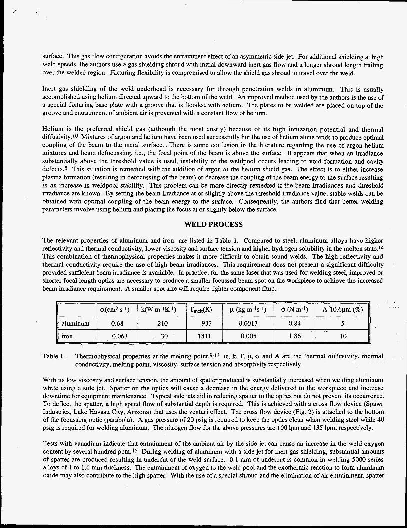
The relevant properties of aluminum and iron are listed in Table 1. Compared to steel, aluminum alloys have higher reflectivity and thermal conductivity, lower viscosity and surface tension and higher hydrogen solubility in the molten state.14 This combination of thermophysical properties makes it more difficult to obtain sound welds. The high reflectivity and thermal conductivity require the use of high beam irradiances. This requirement does not present a significant difficulty provided sufficient beam irradiance is available. In practice, for the same laser that was used for welding steel, improved or shorter focal length optics are necessary to produce a smaller focussed beam spot on the workpiece to achieve the increased beam irradiance requirement. A smaller spot size will require tighter component fitup.
I a(cm2 s-1) 1 k(W m-1K-1) 1 Tmelt(K) I p (kg m-Is-*) I CJ (N m-1) I A - 1 0 . 6 ~ (%) 11
I aluminum 0.68 210 933 0.0013 0.84 5
iron 0.063 30 1811 0.005 1.86 10
Table 1. Thermophysical properties at the melting point.9-13 a, k, T, p, CT and A are the thermal diffusivity, thermal conductivity, melting point, viscosity, surface tension and absorptivity respectively
With its low viscosity and surface tension, the amount of spatter produced is substantially increased when welding aluminum while using a side jet. Spatter on the optics will cause a decrease in the energy delivered to the workpiece and increase downtime for equipment maintenance. Typical side jets aid in reducing spatter to the optics but do not prevent its occurrence. To deflect the spatter, a high speed flow of substantial depth is required. This is achieved with a cross flow device (Spawr Industries, Lake Havasu City, Arizona) that uses the venturi effect. The cross flow device (Fig. 2) is attached to the bottom of the focussing optic (parabola). A gas pressure of 20 psig is required to keep the optics clean when welding steel while 40 psig is required for welding aluminum. The nitrogen flow for the above pressures are 100 Ipm and 135 Ipm, respectively.
Tests with vanadium indicate that entrainment of the ambient air by the side jet can cause an increase in the weld oxygen content by several hundred ppm. 15 During welding of aluminum with a side jet for inert gas shielding, substantial amounts of spatter are produced resulting in undercut of the weld surface. 0.1 mm of undercut is common in welding 5000 series alloys of 1 to 1.6 mm thickness. The entrainment of oxygen to the weld pool and the exothermic reaction to form aluminum oxide may also contribute to the high spatter. With the use of a special shroud and the elimination of air entrainment, spatter

appears to be reduced. The exact amount of spatter is difficult to quantify, but in the welding using a si.de jet, spatter was often observed coming out of the cross-flow device, whereas with the use of the shroud, little or no spatter was observed from the device.
The placement of the laser beam focus on or below the surface of the workpiece can optimize the laser beam coupling to the material. Having the focus above the workpiece produces plasma that defocusses the beam and reduces the irradiance on the surface. Lowering the focus into the workpiece increases the irradiance inside the weldpool which leads to instability effects that may produce increased porosity or dropout.5 However, for deeper weld penetration in thicker material, the focus may need to be inside the material to maintain adequate irradiance for penetration. The optimal Iocation will be affected by the depth of focus of the optics used.
Since magnesium is more volatile than aluminum, loss of magnesium will occur in the weld.1.14 In laser welding, magnesium loss produces a greyish-black deposit downstream of the shielding gas flow on the top weld surface. For normal weld conditions, there is less black deposit or magnesium loss visible on the bottom side of the weld compared to the top. As the beam irradiance is raised substantially above the threshold value for consistent welding, more black deposits appear on the bottom, indicating additional magnesium loss. A beam irradiance that is not much higher than the threshold value for consistent welds is needed to avoid unnecessary magnesium loss as well as keyhole instability effects.
Consideration of the physical mechanisms of keyhole welds in aluminum suggests that some weld quality problems could be ameliorated with conditions that
parabola
cross-flow device \ ' \ I weld monitor
mtput connector shielding gas shroud
rotation stage Figure 2 Annotated photograph of C02 laser beam delivery
system with shielding gas shroud. - produce a lower threshold irradiance. The shorter wavelength and improved absorptivity of NdYAG laser beams compared to the C02 case, allows lower threshold irradiances and easier weld formation.3.4.6J6 Lower threshold irradiances were also obtained for the case of the CO laser.7 The lower threshold irradiances obtained using shorter wavelength laser beams should produce lower magnesium loss, although, magnesium losses for 5000 series alloys are usually c10%.17,18 With the poor precision of microprobe techniques and the lack of definitive data, the actual magnesium loss is difficult to ascertain. Lower threshold irradiances may also produce less spatter and undercut.
WELD MONITORING
For laser welding to be successful in an automotive joining process that produces millions of components, the assurance of weld quality is essential. The primary indicators of weld quality include material characteristics such as weld porosity and microstructure, and physical properties such as weld width and penetration. If the weld material characteristics are constant then the primary indicator of weld quality is usually weld penetration. Weld width is often determined by the fitup tolerance. Online nonintrusive techniques for the monitoring of the material characteristics are presently unavailable. Several methods are available for the monitoring of weld width and penetration.19 A method suited for the manufacturing environment and capable of monitoring the weld surface and penetration is one developed at Argonne National Laboratory and licensed to Spawr Industries (Lake Havasu City, Arizona). It uses a passive detector to monitor the infrared emissions from the weld. The

.-
capabilities of the monitor has been proven on steel components where the AC component of the monitor's analog output signal indicates the state of the weld surface and the DC level is a linear indicator of the weld penetration. Figure 3 is a plot of the weld monitor output signal for a bead-on-plate laser weld on 5182 alloy. The AC signal indicates the high level of spatter and weld pool instability associated with the welding of aluminum. The DC level of the signal is relatively stable for the 1.66 mm penetration weld. The monitoring method works for both C02 and Nd:YAG lasers where the detector is mounted prealigned with the laser beam optical path for functionality and nonobtrusiveness.
Figure 3 Weld monitor signal obtained in C02 laser beam welding (bead on plate) of AA5 182 at 16.9 cm s-1. The beam power used was 4.2 kW, the beam focus diameter was 400 pm and the penetration was 1.66 mm. The darker trace was obtained with a low pass HAM filter set at 342 Hz.
As with all other monitoring methods available, a calibration of the output signal with the parameter of interest is required. The output DC signal can be obtained as a (linear) function of the penetration. The most frequent cause of penetration change is usually associated with change in delivered beam power. For some steel components, 0.05 mm change in penetration can be detected. With aluminum, the higher noise level of the signal decreases the sensitivity to >0.1 mm for the case of the C02 laser.
MATERIAL PROPERTIES
The current interest in aluminum alloys 5182 and 5754 is for autogenous welding of automotive body components. The technological focus is on tailored blank applications where formability and tensile strength of the weld are important. These material properties tests are very dependent on the geometry of the specimens used. Values quoted for this discussion are from Alcan for formability and Reynolds for tensile strength.
Results published for AA 5754 indicate that welds obtained with CO2 and Nd:YAG lasers at welding speeds of approximately 6 cm s-1 have comparable tensile strengths with ultimate and yield strengths exceeding 90% of parent metal.16 However, the elongation obtained was 83% and 64% of the value of 16.9% for the parent metal for the case of CO;! and Nd:YAG respectively. Welds produced at Argonne with a similar side jet as the above data but with a smaller spot size beam produced elongation of approximately 8%. This lower value was obtained for welds produced at weld speeds from 4 to 17 cm s-1. Other data for 5000 series alloys indicate slower welding speeds tend to produce welds with better strength and elongation.20 At slower welding speeds, the weld widths obtained are wider and the microstructure may be different. In addition, loss of magnesium may lead to a decrease in strength and increase the elongation.
.
Corresponding formability (punch dome test) results obtained using a Nd:YAG laser yielded values of approximately 70% of the parent metal,. 16 Data obtained at Argonne with a C02 laser produced formability of 50 to 60% of parent metal. Edge preparation (using shear cut, dry milled or wire brushed edges) did not appear to have a significant effect on the formability. The presence of oxide inclusions caused by. the entrained ambient air may contribute to the low formability values obtained. Fracture during dome height testing for the above data occurred in the fusion zone. This result would be expected because there is an increase in hardness of approximately 10% 'in the fusion zone. In addition, undercut is detrimental to both formability and tensile strength.21

It is evident that the welds obtained have degraded material properties compared to the parent material. Several of the process parameters appear to have impacts on the weld quality. However, the published data have many inconsistent trends. With the imprecision or lack in details of the published data, it is difficult to compare the results on the same basis yet determine the controlling parameters.
SUMMARY AND CONCLUSIONS
Recent efforts on C02 and Nd:YAG laser beam welding have resolved several of the initial problems associated with the welding of 5000 series aluminum alloys. Consistent and repeatable welds can now be obtained without resorting to meticulous edge preparation. Trouble-free operation of the optics has been achieved with the use of a cross-flow system developed with Spawr Industries. The effect of plasma formation during welding has been clarified. Elimination or reduction of the plasma is recommended for optimal welding of aluminum in contrast to results by other groups’that advocate inert gas blends. The data obtained show that a simple cross jet reentrains ambient air and does not provide complete inert gas shielding. Initial data obtained with a weld monitor indicate that weld surface quality and penetration can be monitored in real- time and nonintrusively.
Further work is needed to develop the weld process parameters necessary to achieve the materials characteristics required for the use of aluminum alloys in automotive applications. Improved gas shielding requirements are expected to be critical to obtaining welds with the required materials properties. Further studies are needed to determine the parameters controlling weld quality. Additional work is also needed to develop a turnkey version of a weld monitor for both C02 and Nd:YAG laser weld quality assurance. This paper has focused on recent work at Argonne and has not included data from other projects on laser beam welding of aluminum that have not appeared in the open literature.
ACKNOWLEDGEMENTS
This work was supported in part by the U.S. Department of Energy, Office of Energy Research Laboratory Technology Research Program and the Office of Transportation Technologies. Ken Sabo was a Laboratory-Graduate Participant in a program administered by the Argonne Division of Educational Programs with funding from the U.S. Department of Energy. The authors would like to thank Bernie Altshuller of Alcan International Limited and Tom Wilkinson of Reynolds Metals Company for providing aluminum alloy samples and performing formability and tensile tests of the welded samples.
~
REFERENCES
1.
2.
3.
4.
5.
6.
W. M. Steen, Laser Material Processing, Springer-Verlag, London, 1994.
D. A. Belforte, “Worldwide automotive applications drive laser growth and development”, Automotive Laser Applications Workshop, March 5-6, Novi, Michigan, 1996.
H. Sakamoto, K. Shibata and F. Dausinger, “Laser welding of different aluminum alloys”, Proceedings of Laser Materials Processing Symposium (ICALEO’92), October 25-29, Orlando, Florida, 523-28, 1992.
J. Berkmanns, R. Imhoff, K. Behler and E. Beyer, “Laser welding of aluminum”, Automotive Laser Applications Workshop, March 6-7, Dearborn, Michigan, 1995.
R. P. Martukanitz and D. J. Smith, “Laser beam welding of aluminum alloys”, Proceedings Sixth International Conference on Aluminum Weldments, April 3-5, Cleveland, Ohio, 309-23, 1995.
F. Dausinger, F. Faisst, R. Hack, J. Rapp, H. Huge1 and M. Beck, “Welding of aluminum: challenge and chance for laser technology”, Proceedings of Laser Materials Processing Symposium (ICALEO ’9.51, November 13- 16, San Diego, California, 1059-67, 1995.

7. B. A. Mehmetli, K. Takahashi and S . Sato, “Comparison of aluminum alloy welding characteristics with 1 kW CO and C02 lasers”, J. Laser Applications, 8, 25-31, 1996.
8 . K. H. Leong, D. J. Holdridge, M. G. Seibert and D. E. Nelson, “High Speed Laser Welding for Automotive Exhaust Applications”, 27th International Symposium on Automotive Technology and Automution, 3 1 October - 4 November, 413-18, Aachen, Germany, 1994.
9. C. J. Nonhof, Material processing with Nd-lasers, Electrochemical Publications, Ayr, Scotland, 1988.
IO. A. G. Grigoryants, Basics of Laser Material Processing, Mnr Publishers, Moscow, 1994.
11. Toulokian, Y. S., Powell, R. W., Ho, C. Y., and Nicolaou, M. C. Thermal Diffusivity, Thermophysical Properties of Matter, Vol. 10, IFI/Plenum, New York, 1973.
12. Toulokian, Y. S., Powell, R. W., Ho, C. Y., and Nicolaou, M. C. Thermal Conductivity Metallic Elements and Alloys, Thermophysical Properties of Matter, Vol. 1, IFWPlenum, New York, 1970. ’
13. Prokhorov, A. M., Konov, V., Ursu, I., and Mihailescu, I. N. Laser Heating of Metals. Adam Hilger, New York, 1990.
14. W. R. Oates, editor, “Welding Handbook”, vol. 3, Materials and Applications, American Welding Society, Miami Florida, 1996.
15. R. V. Strain, “Results of oxygen analyses on laser welds”, Argonne Fusion Power Program Progress Report, 1996.
16. R. P. Martukanitz and B. Altshuller, “Laser beam welding of aluminum alloy 5754-0 using a 3kW NdYAG laser and fiber optic beam delivery”, Proceedings of Laser Materials Processing Symposium (ICALEO’96), October 14- 17, Southfield, Michigan, 1966.
17. A. Blake and J. Mazumder, “Control of magnesium loss during laser welding of AI-5083 using a plasma suppression technique”, J. Engineering for Industry, 107,275-80, 1985.
18. D. W. Moon and E. A. Metzbower, “Laser beam welding of aluminum alloy 5456”, Welding J., 62,53~-58s, 1983.
19. C. T. Walters and S . L. Ream, “Laser weld process monitoring in production of tailor-welded blanks”, Proceedings of Laser Materials Processing Symposium (ICALEO’96), October 14-17, Southfield, Michigan, 1996.
20. I. Jones, J. Yoon, S . Riches and E. Wallach, “Quality assessment of laser welding in automotive aluminum alloys”, Proceedings 27th International Symposium on Automotive Technology and Automation, 31 October - 4 November, Aachen, Germany, 441-47, 1994. I
21. F. V. Lawrence, “ Fatigue resistance of laser welds versus spot welds”, Automotive Laser Applications Workshop, March 5-6, Novi, Michigan, 1996.