Embed Size (px)
Citation preview
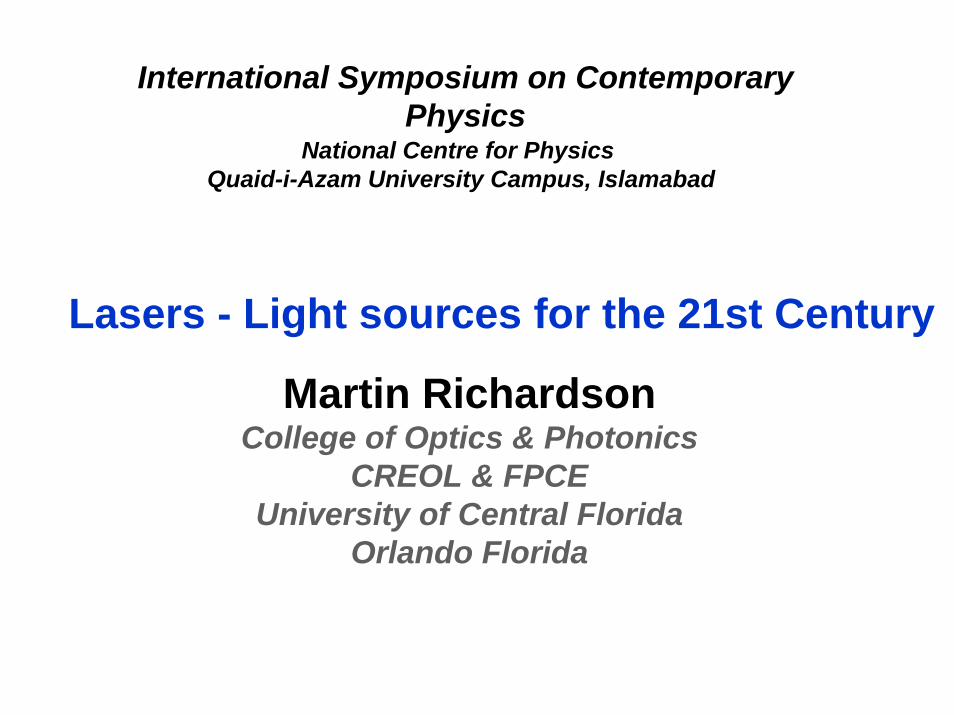
Martin RichardsonCollege of Optics & Photonics
CREOL & FPCEUniversity of Central Florida
Orlando Florida
International Symposium on Contemporary Physics
Lasers - Light sources for the 21st Century
National Centre for Physics Quaid-i-Azam University Campus, Islamabad
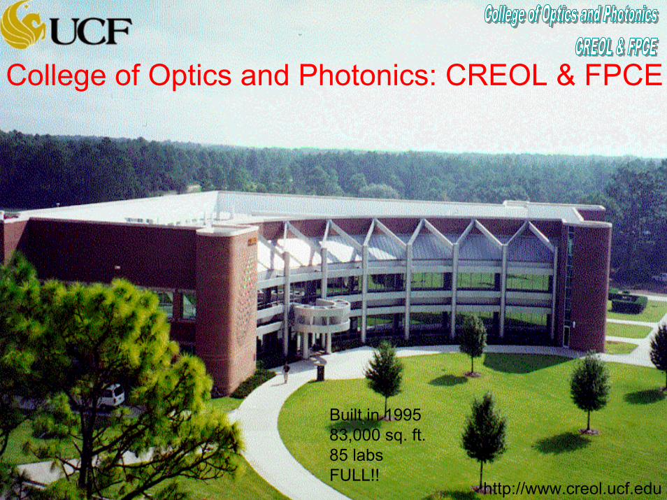
Built in 199583,000 sq. ft.85 labsFULL!!
http://www.creol.ucf.edu
College of Optics and Photonics: CREOL & FPCE

One of the three major optics graduate research schools in the USA
The Col legeof Optics & Photnoics at the University of Central Florida

OPTICS IS AN ENABLING, PERVASIVE TECHNOLOGY . . .
In the Homeh TV remote h CD playerh CD ROM h Motion sensorh Smoke detectorh Light bulbsh Etc.
In Medicineh Tattoo removalh Various types of surgeryh Vision correctionh Various diagnosticsh Cosmetic surgeryh Blood monitorsh Etc.
In the EconomyIn the Economyhh TelecommunicationsTelecommunicationshh Bar code scannersBar code scannershh SurveyingSurveyinghh All sorts of manufacturingAll sorts of manufacturinghh Crop dustingCrop dustinghh EntertainmentEntertainmenthh Etc.Etc.
In National Defense In National Defense hh Night visionNight visionhh Reconnaissance systemsReconnaissance systemshh CommunicationsCommunicationshh Range findersRange findershh DesignatorsDesignatorshh Smart weaponsSmart weaponshh Etc.Etc.
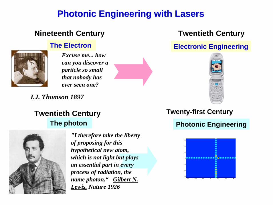
Photonic Engineering with LasersPhotonic Engineering with Lasers
J.J. Thomson 1897
Excuse me... how can you discover a particle so small that nobody has ever seen one?
Nineteenth Century Twentieth Century
Twentieth Century
"I therefore take the liberty of proposing for this hypothetical new atom, which is not light but plays an essential part in every process of radiation, the name photon.“ Gilbert N. Lewis, Nature 1926
The Electron Electronic Engineering
Twenty-first CenturyThe photon Photonic Engineering
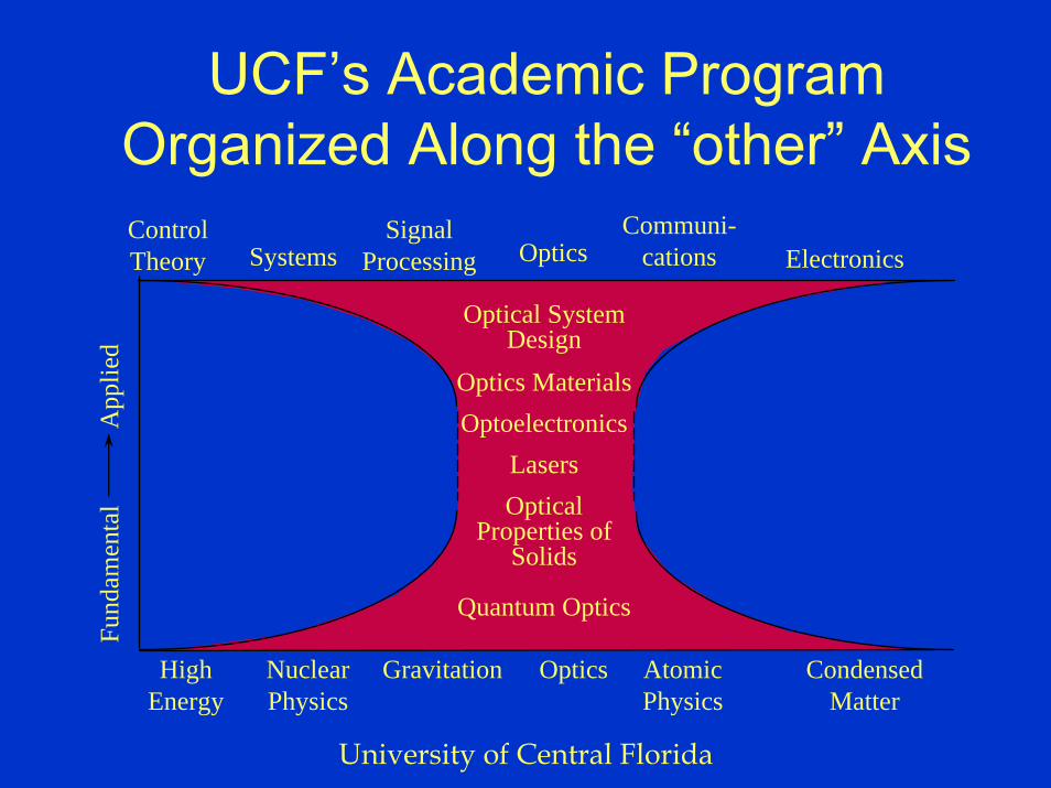
UCF’s Academic ProgramOrganized Along the “other” AxisControlTheory Systems
SignalProcessing
Communi-cationsOptics Electronics
Optical System Design
Optics MaterialsOptoelectronics
LasersOptical
Properties of Solids
Quantum Optics
Fund
amen
tal
App
lied
High Energy
NuclearPhysics
Gravitation AtomicPhysics
Optics CondensedMatter
University of Central Florida
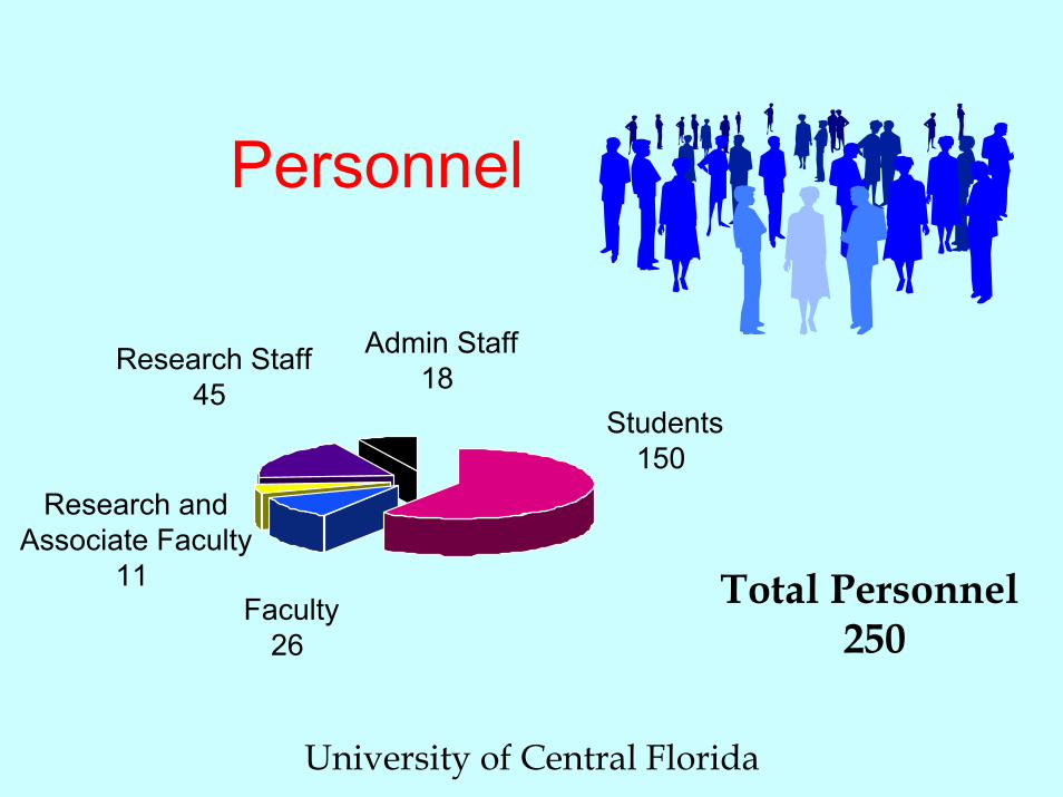
Personnel
University of Central Florida
Admin Staff18 Research Staff
45
Faculty26
Students150
Total Personnel 250
Research andAssociate Faculty
11
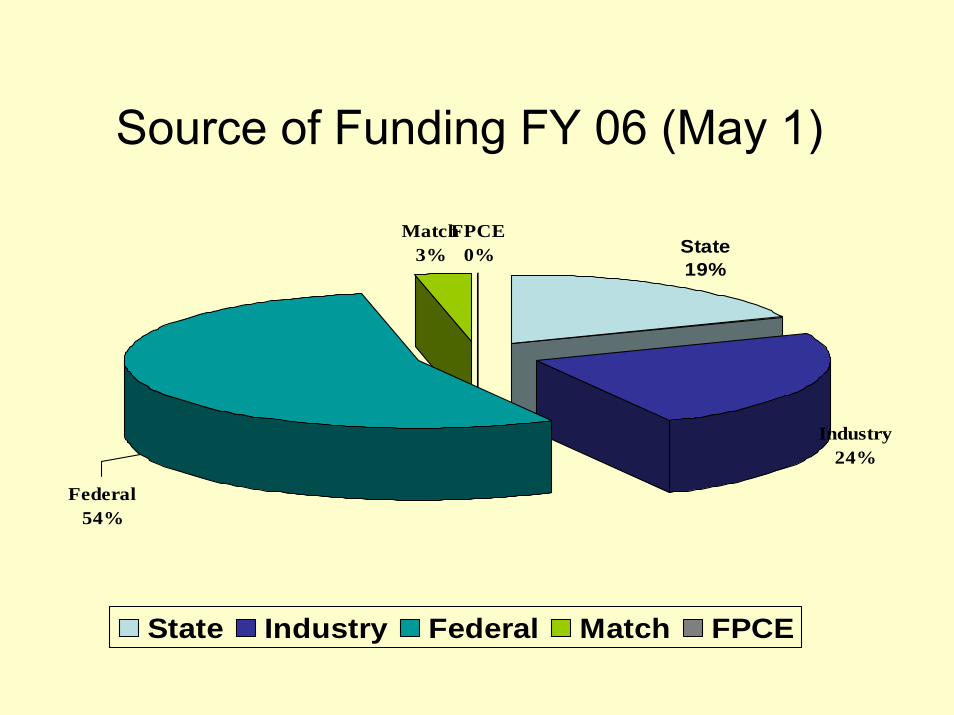
Source of Funding FY 06 (May 1)
Match3%
FPCE0% State
19%
Federal54%
Industry24%
State Industry Federal Match FPCE

Optics CoursesOptics CoursesOSEOSE--505X Fund. and Appl. of Photonics 505X Fund. and Appl. of Photonics OSEOSE--5111 Optical Wave Propagation 5111 Optical Wave Propagation OSEOSE--5115 Interference and Diffraction 5115 Interference and Diffraction OSEOSE--5143 Fiber Optics Communication 5143 Fiber Optics Communication OSEOSE--5203 Geometrical Optics 5203 Geometrical Optics OSEOSE--5234L Applied Optics Laboratory5234L Applied Optics LaboratoryOSEOSE--5312 Optical Properties of Materials5312 Optical Properties of MaterialsOSEOSE--5414 Fundamentals of Optoelectronics5414 Fundamentals of OptoelectronicsOSEOSE--542X Integrated Optics 542X Integrated Optics OSEOSE--5511 Laser Principles 5511 Laser Principles OSEOSE--5630C Thin Film Optics 5630C Thin Film Optics OSEOSE--6118 Optical Propagation in 6118 Optical Propagation in
Inhomogeneous Media Inhomogeneous Media OSEOSE--6211 Fourier Optics 6211 Fourier Optics OSEOSE--6225 Radiation and Detection 6225 Radiation and Detection OSEOSE--6265 Optical Systems Design 6265 Optical Systems Design OSEOSE--6335 Nonlinear Guided Wave Optic6335 Nonlinear Guided Wave OpticOSEOSE--6347 Quantum Optics6347 Quantum Optics
University of Central Florida
PHYPHY--5455 Modern X5455 Modern X--ray Science ray Science OSEOSE--6334 Nonlinear Optics 6334 Nonlinear Optics OSEOSE--641XL Optoelectronic Device 641XL Optoelectronic Device
Fabrication Laboratory Fabrication Laboratory OSEOSE--6432 Electro6432 Electro--optics optics OSEOSE--6445 High Speed Photonics 6445 High Speed Photonics OSEOSE--6455L Photonics Laboratory 6455L Photonics Laboratory OSEOSE--6457 Photonics Signal Processing 6457 Photonics Signal Processing OSEOSE--6526L Laser Engineering Laboratory6526L Laser Engineering LaboratoryOSEOSE--6528 Specific Laser Systems 6528 Specific Laser Systems OSEOSE--6534 Solid State Laser 6534 Solid State Laser OSEOSE--6560 Laser Engineering 6560 Laser Engineering OSEOSE--657X Optical Networks 657X Optical Networks OSEOSE--6644 Advanced Microlithography 6644 Advanced Microlithography PHYPHY--5455 Modern X5455 Modern X--ray Science ray Science PHZPHZ--5505 Plasma Physics5505 Plasma PhysicsMEAMEA--5610 Laser Material Processing5610 Laser Material Processing
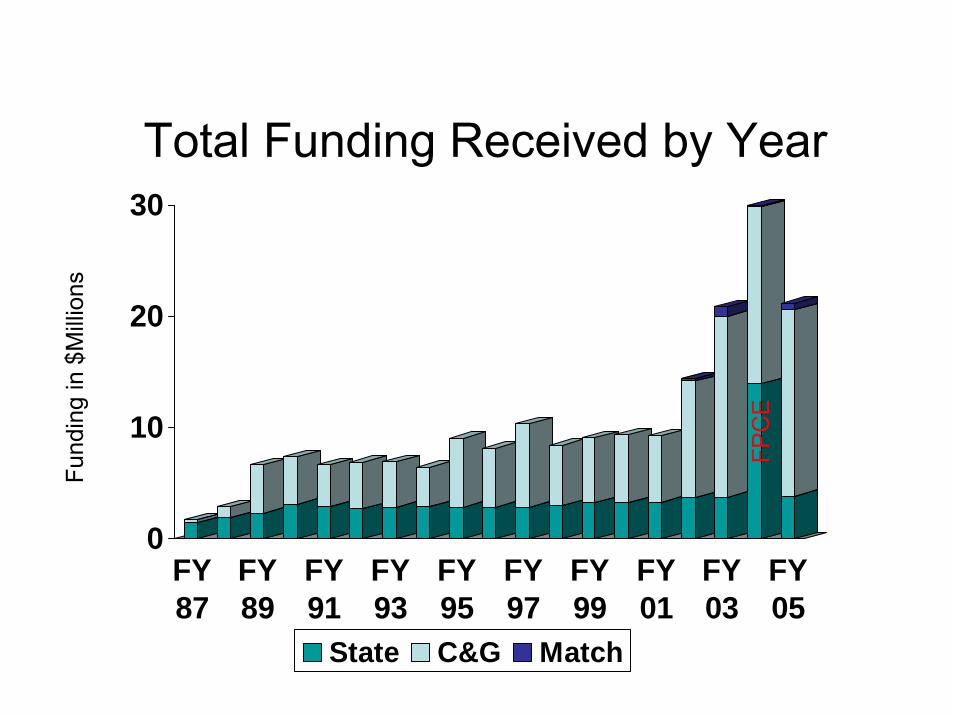
Total Funding Received by Year
0
10
20
30
FY87
FY89
FY91
FY93
FY95
FY97
FY99
FY01
FY03
FY05
State C&G Match
Fund
ing
in $
Mill
ions
FPC
E
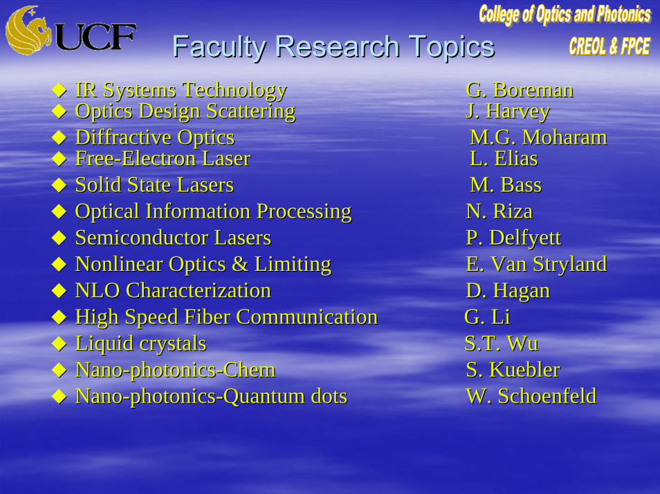
Faculty Research TopicsFaculty Research TopicsIR Systems TechnologyIR Systems Technology G. G. BoremanBoremanOptics Design ScatteringOptics Design Scattering J. HarveyJ. HarveyDiffractive OpticsDiffractive Optics M.G. M.G. MoharamMoharamFreeFree--Electron LaserElectron Laser L. EliasL. EliasSolid State LasersSolid State Lasers M. BassM. BassOptical Information ProcessingOptical Information Processing N. N. RizaRizaSemiconductor LasersSemiconductor Lasers P. P. DelfyettDelfyettNonlinear Optics & LimitingNonlinear Optics & Limiting E. Van E. Van StrylandStrylandNLO CharacterizationNLO Characterization D. HaganD. HaganHigh Speed Fiber Communication High Speed Fiber Communication G. LiG. LiLiquid crystals Liquid crystals S.T. WuS.T. WuNanoNano--photonicsphotonics--ChemChem S. S. KueblerKueblerNanoNano--photonicsphotonics--Quantum dotsQuantum dots W. W. SchoenfeldSchoenfeld

Faculty Research TopicsFaculty Research TopicsNonlinear Guided-wave Optics G. Stegeman Laser Induced Damage M.J. SoileauQuantum Well Optoelectronics P. LiKamWaX-ray Sources, Lithography W. SilfvastUltrashort Pulse, X-rays, Plasma Physics M. RichardsonLaser Processing of Materials A. KarTheory of Light/Matter Interactions B. Zel’dovichVirtual Reality & 3D Imaging Systems J. RollandOptical Diagnostics, Scattering A. DogariuDiffractive optics for Telecom. E. JohnsonPhotorefractive glass L. GlebovLasers and host crystal growth H. JenssenOPTICS! E. WolfSoliton theory for telecom D. ChristodoulidesNano-photonics P. Kik
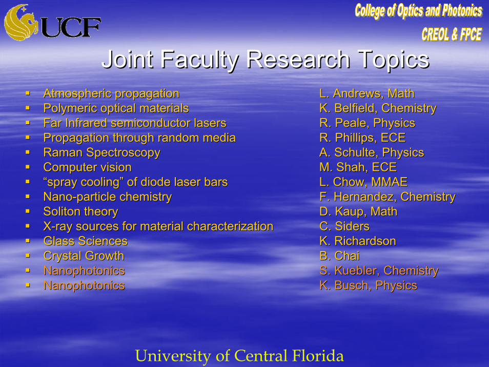
Joint Faculty Research TopicsJoint Faculty Research TopicsAtmospheric propagationAtmospheric propagation L. Andrews, MathL. Andrews, MathPolymeric optical materialsPolymeric optical materials K. Belfield, ChemistryK. Belfield, ChemistryFar Infrared semiconductor lasersFar Infrared semiconductor lasers R. Peale, PhysicsR. Peale, PhysicsPropagation through random mediaPropagation through random media R. Phillips, ECER. Phillips, ECERaman SpectroscopyRaman Spectroscopy A. Schulte, PhysicsA. Schulte, PhysicsComputer visionComputer vision M. Shah, ECEM. Shah, ECE““spray coolingspray cooling”” of diode laser barsof diode laser bars L. Chow, MMAEL. Chow, MMAENanoNano--particle chemistryparticle chemistry F. Hernandez, ChemistryF. Hernandez, ChemistrySolitonSoliton theorytheory D. D. KaupKaup, Math, MathXX--ray sources for material characterization ray sources for material characterization C. C. SidersSidersGlass SciencesGlass Sciences K. RichardsonK. RichardsonCrystal Growth Crystal Growth B. B. ChaiChaiNanophotonicsNanophotonics S. S. KueblerKuebler, Chemistry, ChemistryNanophotonicsNanophotonics K. Busch, PhysicsK. Busch, Physics
University of Central Florida
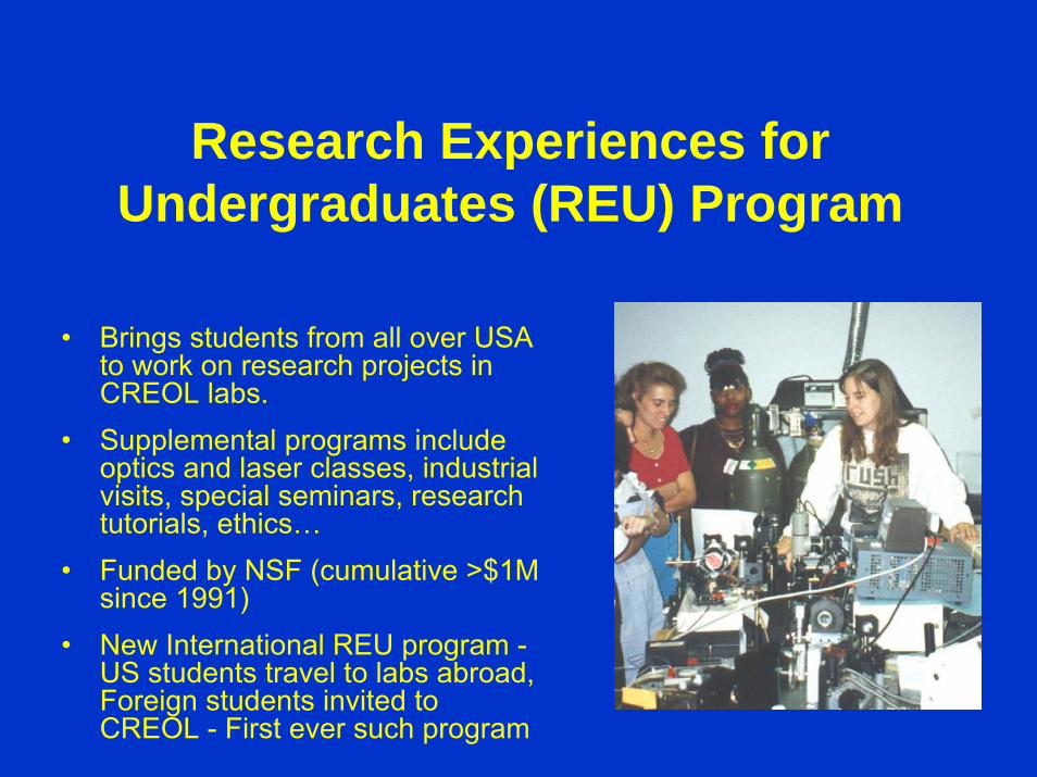
Research Experiences for Undergraduates (REU) Program
• Brings students from all over USA to work on research projects in CREOL labs.
• Supplemental programs include optics and laser classes, industrial visits, special seminars, research tutorials, ethics…
• Funded by NSF (cumulative >$1M since 1991)
• New International REU program -US students travel to labs abroad, Foreign students invited to CREOL - First ever such program
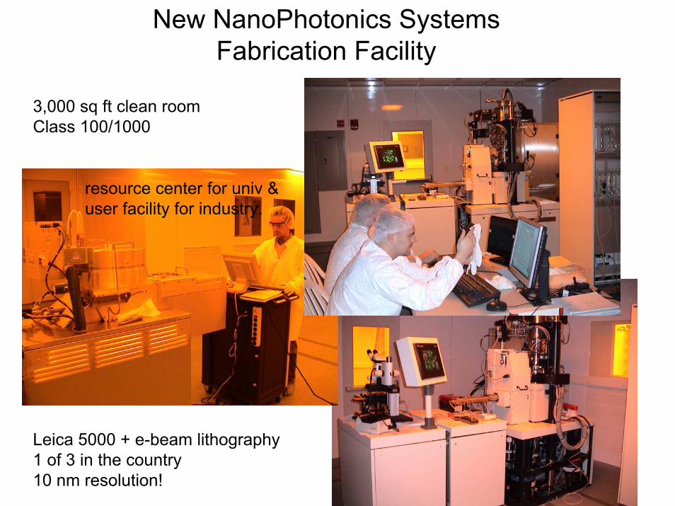
New NanoPhotonics SystemsFabrication Facility
3,000 sq ft clean roomClass 100/1000
Leica 5000 + e-beam lithography1 of 3 in the country10 nm resolution!
resource center for univ &user facility for industry.
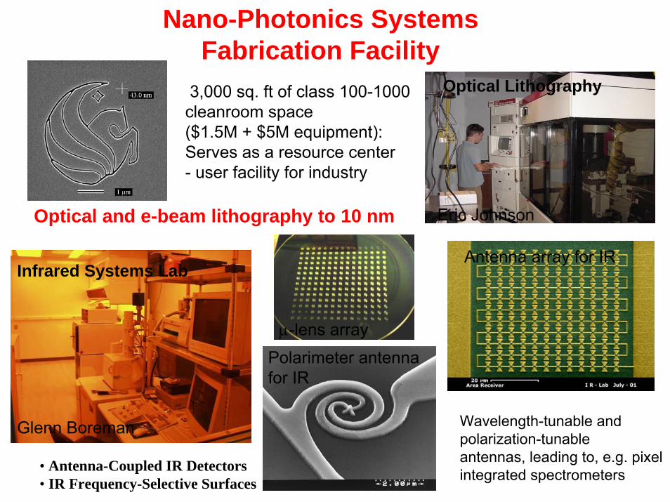
• Antenna-Coupled IR Detectors• IR Frequency-Selective Surfaces
Wavelength-tunable and polarization-tunableantennas, leading to, e.g. pixel integrated spectrometers
Infrared Systems Lab
Glenn Boreman
Optical and e-beam lithography to 10 nm
Optical Lithography
Eric Johnson
Polarimeter antennafor IR
3,000 sq. ft of class 100-1000cleanroom space($1.5M + $5M equipment): Serves as a resource center- user facility for industry
Nano-Photonics SystemsFabrication Facility
Antenna array for IR
μ-lens array
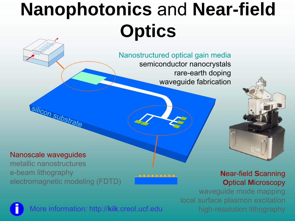
Nanophotonics and Near-field OpticsNanostructured optical gain media
semiconductor nanocrystalsrare-earth doping
waveguide fabrication
More information: http://kik.creol.ucf.edu
silicon substrate
Near-field Scanning Optical Microscopy
waveguide mode mapping local surface plasmon excitation
high-resolution lithography
Nanoscale waveguidesmetallic nanostructurese-beam lithographyelectromagnetic modeling (FDTD)

New Lithography fabricated IR optics
( Glenn Boreman, CREOL)Extension of RF concepts to IR through advanced lithography
• Antenna-Coupled IR Detectors• IR Frequency-Selective Surfaces• THz & mm-Wave Sensors


The Ruby Laser The Ruby Laser
1960
1964
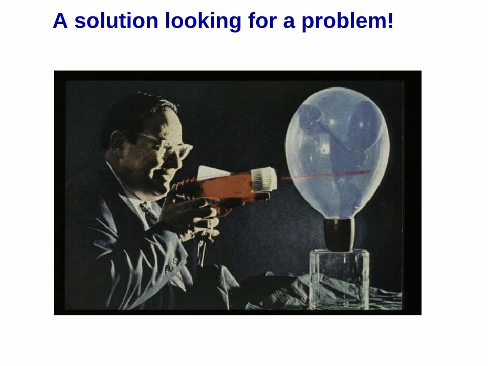
A solution looking for a problem!

THE LARGEST LASER IN THE WORLD THE LARGEST LASER IN THE WORLD National Ignition Facility 192 beams, 4 MJ per pulse
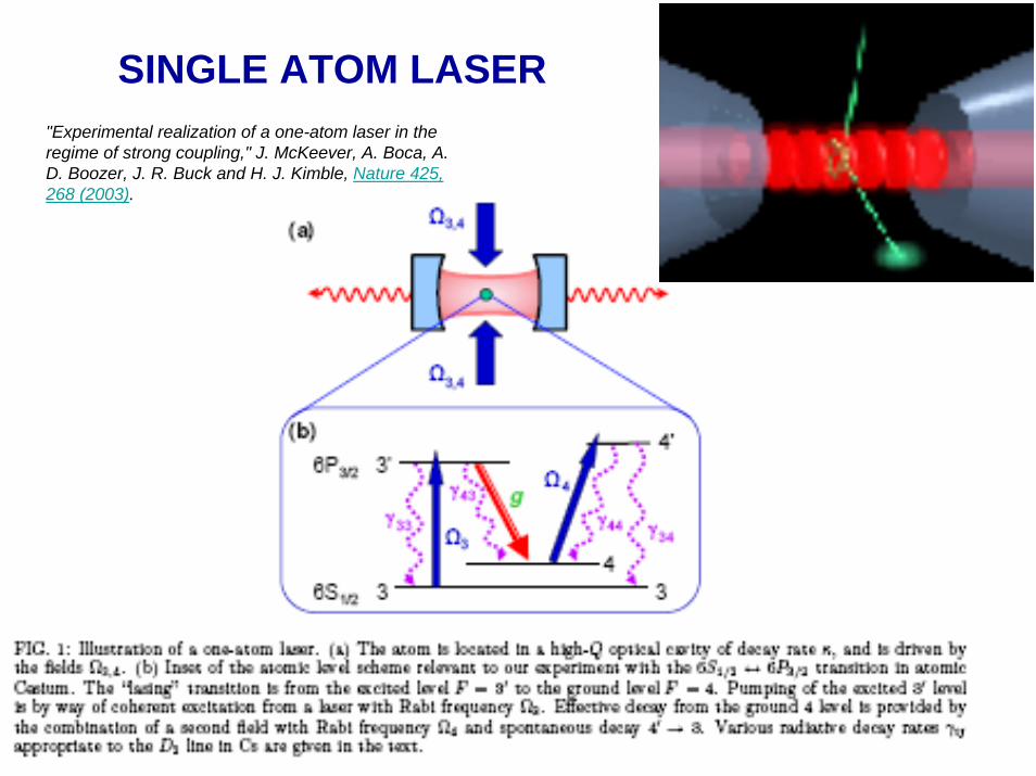
"Experimental realization of a one-atom laser in the regime of strong coupling," J. McKeever, A. Boca, A. D. Boozer, J. R. Buck and H. J. Kimble, Nature 425, 268 (2003).
SINGLE ATOM LASER
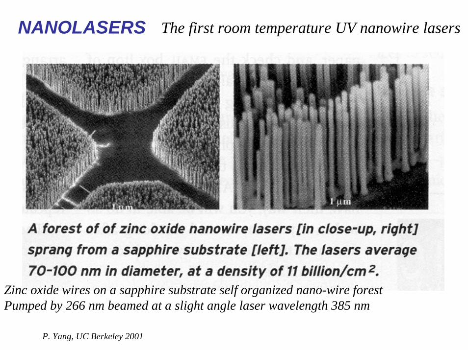
NANOLASERS
P. Yang, UC Berkeley 2001
Zinc oxide wires on a sapphire substrate self organized nano-wire forestPumped by 266 nm beamed at a slight angle laser wavelength 385 nm
The first room temperature UV nanowire lasers

Absorption and Stimulated Emission We can write the rate of change of population
2212 NW
dtdN
st
−=⎟⎠⎞
⎜⎝⎛
E1
E2
Stimulated Emission
N2
N1
E1
E2
Absorption
N2
N1
However, now the rate of stimulated emissionis dependent on the intensity of the EM wave
FW 2121 σ=
stimulated emission cross-section (units = area)
Photon flux (number of photons/ unit area/unit time)
Similarly for Absorption
1121 NW
dtdN
ab
−=⎟⎠⎞
⎜⎝⎛
FW 1212 σ=
absorption cross-section
Courtesy A. Siegman

Courtesy A. Siegman

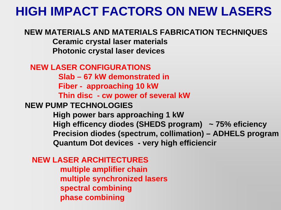
NEW LASER CONFIGURATIONSSlab – 67 kW demonstrated in Fiber - approaching 10 kWThin disc - cw power of several kW
NEW PUMP TECHNOLOGIESHigh power bars approaching 1 kWHigh efficency diodes (SHEDS program) ~ 75% eficiencyPrecision diodes (spectrum, collimation) – ADHELS programQuantum Dot devices - very high efficiencir
NEW MATERIALS AND MATERIALS FABRICATION TECHNIQUESCeramic crystal laser materialsPhotonic crystal laser devices
HIGH IMPACT FACTORS ON NEW LASERS
NEW LASER ARCHITECTURESmultiple amplifier chainmultiple synchronized lasersspectral combiningphase combining
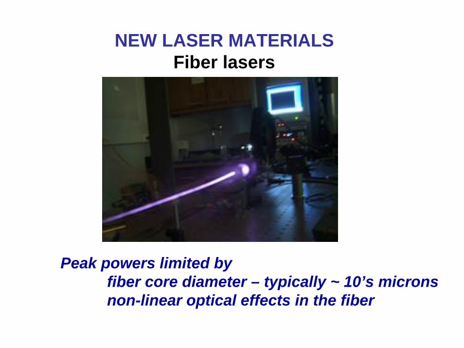
NEW LASER MATERIALSFiber lasers
Peak powers limited byfiber core diameter – typically ~ 10’s micronsnon-linear optical effects in the fiber

High Power Fiber Lasers - JTO MRI 2005PI’s: John Ballato, Clemson Univ., Martin Richardson, UCF
Program Goals• Develop kW class “eye-safe” fiber lasers.• Focus on novel materials and designs.• Guiding Principles: Large mode area, purely single mode, single frequency,
and polarization, minimize nonlinear effects, buffer coating greater then 200°C stability.
Fundamental Significance• Focus on erbium 1.55 μm emission and thulium “2-for-1” emission at 2 μm.• Silica and non-silica materials focusing on (a) multicores and (b) gain-guiding.
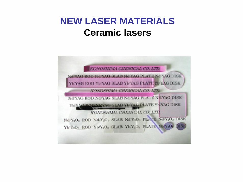
NEW LASER MATERIALSCeramic lasers

NEW LASER MATERIALSNovel high power optics
Writingbeam
PTR glass Writingbeam
Readingbeam
Transmittedbeam
Diffractedbeam
Bragg grating
Leon Glebov - Photo-Thermal-Refractive (PTR) glass
APPLICATIONS•Conventional opticsbeam splitters, polarizers, atten.•Laser systemsattenuators, mode selectors, ...•Opt. Com.- WDM filters, add/drop, equalizers, ...•Data storage -unlimited reading
Volume Holograms in Glass
Multiple integrated optics functionalitye.g. lens, pol., grating, mirror, filter, etc.
e.g. Na doublet (0.6 nm) resolved without collimator or slit
e.g. Na doublet (0.6 nm) resolved without collimator or slit
Optics in a 3-D chip
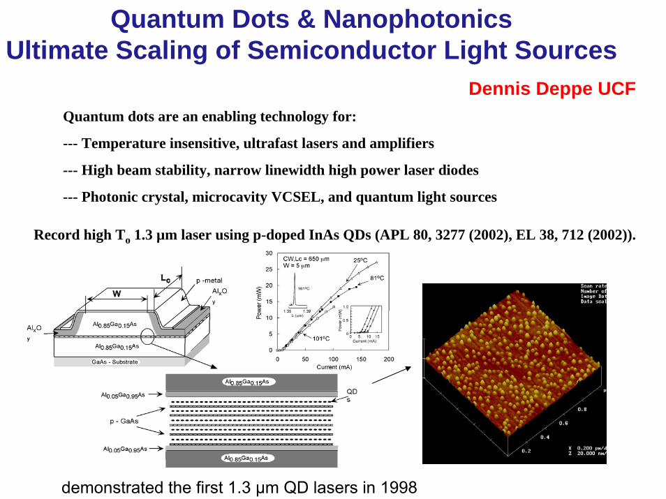
Quantum Dots & NanophotonicsUltimate Scaling of Semiconductor Light Sources
Quantum dots are an enabling technology for:
--- Temperature insensitive, ultrafast lasers and amplifiers
--- High beam stability, narrow linewidth high power laser diodes
--- Photonic crystal, microcavity VCSEL, and quantum light sources
Record high To 1.3 µm laser using p-doped InAs QDs (APL 80, 3277 (2002), EL 38, 712 (2002)).
Dennis Deppe UCF
demonstrated the first 1.3 µm QD lasers in 1998
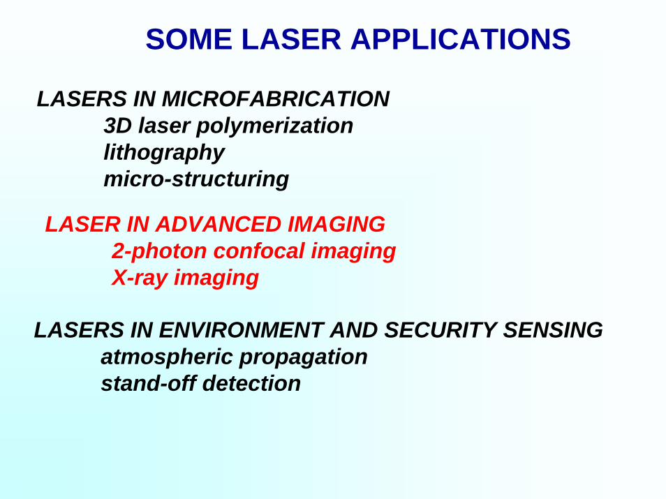
SOME LASER APPLICATIONS
LASERS IN MICROFABRICATION3D laser polymerizationlithographymicro-structuring
LASER IN ADVANCED IMAGING2-photon confocal imagingX-ray imaging
LASERS IN ENVIRONMENT AND SECURITY SENSINGatmospheric propagationstand-off detection

• Micro-fluidics• Micro-optical devices• Bio-nanophotonic systems
CAD-defined target structure
Final structure
Automated 3Dmicrofabrication
Cumpston et al., Nature, 1999Kuebler et al., J. Photopolym. Sci. Technol., 2001Zhou et al., Science, 2002

Lithography is the technology that produces today’s computers
Process
0.130mm process
Pentium 4™
Minimumfeatures size
NAkW λ1=
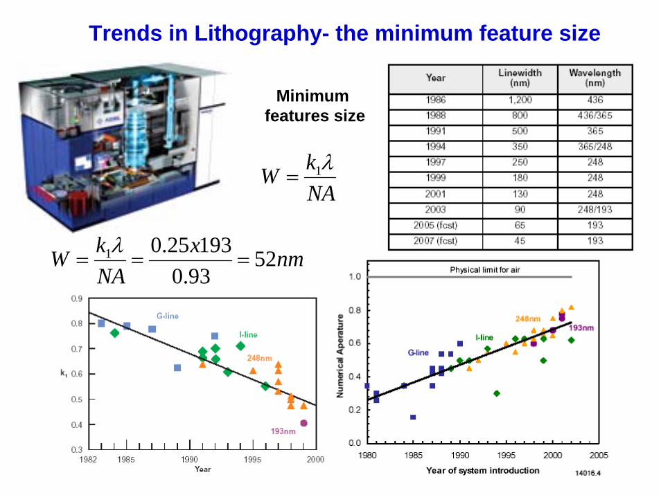
Trends in Lithography- the minimum feature size
nmxNAkW 52
93.019325.01 ===
λ
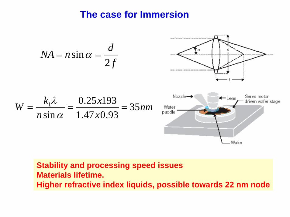
The case for Immersion
fdnNA
2sin == α
nmxx
nkW 35
93.047.119325.0
sin1 ===
αλ
Stability and processing speed issuesMaterials lifetime.Higher refractive index liquids, possible towards 22 nm node

The computer chip industry is driven by Lithography
Computer chip development has been governed for 30 years by Moore’s Law

The minimum feature size on a computer chipFrom microelectronics into the world of nanotechnology

Today’s computer chips are made with UV laser light sources
The wavelength of these UV sources is too large for tomorrow’s lithography…
Lithography machine
Minimum feature size
Wavelength
NAk1=W λ

Tomorrow’s lithography will use EUV sources
Year 2010 Wavelength λ =13 nm (EUV) Completely new optics for lithography
Use mirrors instead of lenses
0.0
0.2
0.4
0.6
0.8
1.0
12.5 13.0 13.5 14.0 14.5Wavelength (nm)
Mo-Si multilayer mirrorReflectivity 68% at 13.5nm
New type of lithography machine
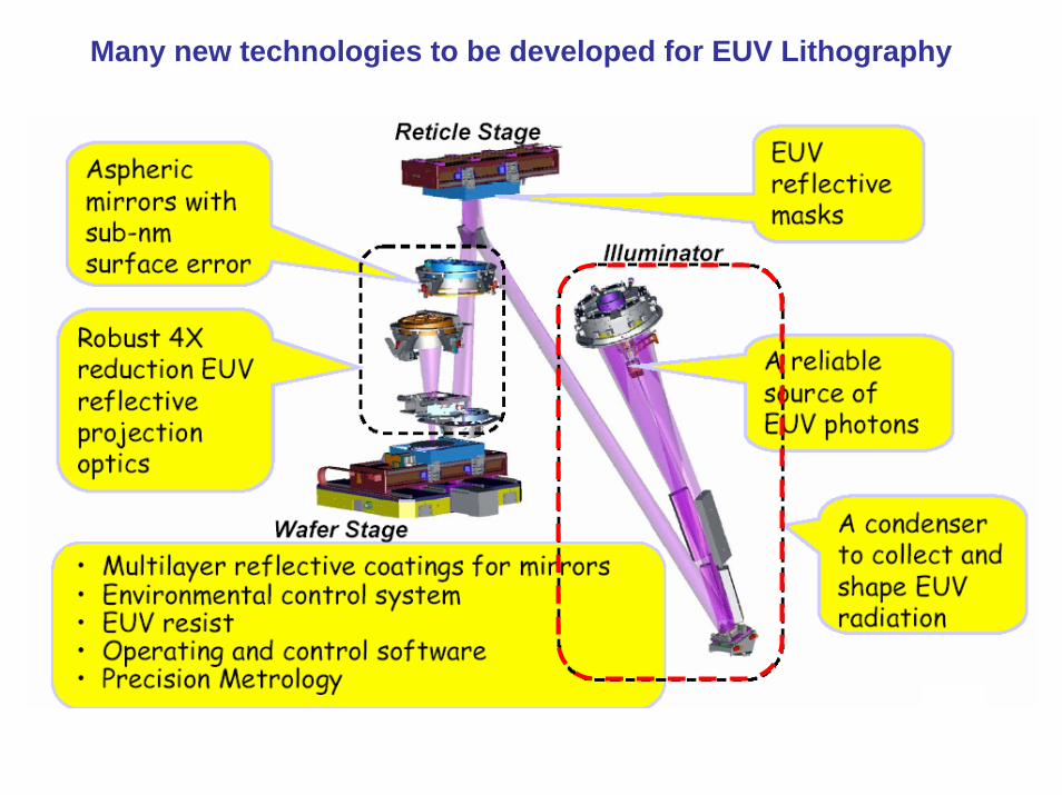
Many new technologies to be developed for EUV Lithography

The IR - visible – UV region The x-ray region
The EUV – Soft X-ray region
The EUV The EUV –– Soft XSoft X--ray region of the electromagnetic spectrumray region of the electromagnetic spectrum
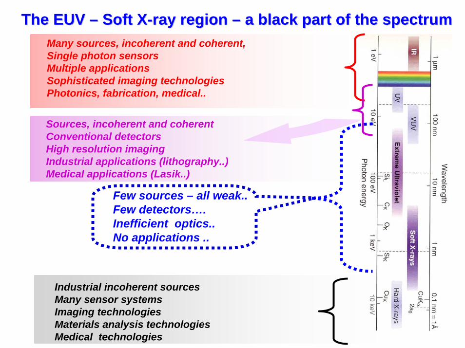
The EUV The EUV –– Soft XSoft X--ray region ray region –– a black part of the spectruma black part of the spectrumMany sources, incoherent and coherent,Single photon sensorsMultiple applicationsSophisticated imaging technologiesPhotonics, fabrication, medical..
Sources, incoherent and coherentConventional detectorsHigh resolution imagingIndustrial applications (lithography..)Medical applications (Lasik..)
Industrial incoherent sourcesMany sensor systemsImaging technologiesMaterials analysis technologiesMedical technologies
Few sources – all weak..Few detectors….Inefficient optics..No applications ..
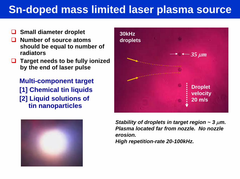
Sn-doped mass limited laser plasma source
Multi-component target[1] Chemical tin liquids[2] Liquid solutions of
tin nanoparticles
Small diameter dropletNumber of source atoms should be equal to number of radiatorsTarget needs to be fully ionized by the end of laser pulse
Stability of droplets in target region ~ 3 μm.Plasma located far from nozzle. No nozzle erosion. High repetition-rate 20-100kHz.
35 μm
Dropletvelocity20 m/s
30kHz droplets
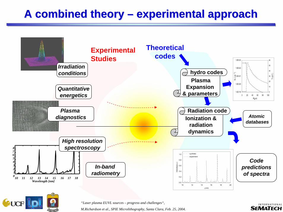
“Laser plasma EUVL sources – progress and challenges“,
M.Richardson et al., SPIE Microlithography, Santa Clara, Feb. 25, 2004.
A combined theory A combined theory –– experimental approachexperimental approach
1.0E+19
1.0E+20
1.0E+21
1.0E+22
1.0E+23
0 20 40 60 80 100R(μm)
Ne (
cm-3
)
0
10
20
30
40
50
60
Te(e
V)
10 11 12 13 14 15 16 17 18
876543210
Wavelength [nm]
hydro codesPlasma
Expansion& parameters
Theoretical codes
Experimental Studies
Irradiation conditions
Quantitativeenergetics
Plasma diagnostics
High resolutionspectroscopy
In-band radiometry
0.0
0.2
0.4
0.6
0.8
1.0
10 12 14 16 18 20
λ(nm)
Inte
nsity
(a.u
.)
synthetic
experiment
Radiation codeIonization &
radiation dynamics
Atomic databases
Code predictions of spectra
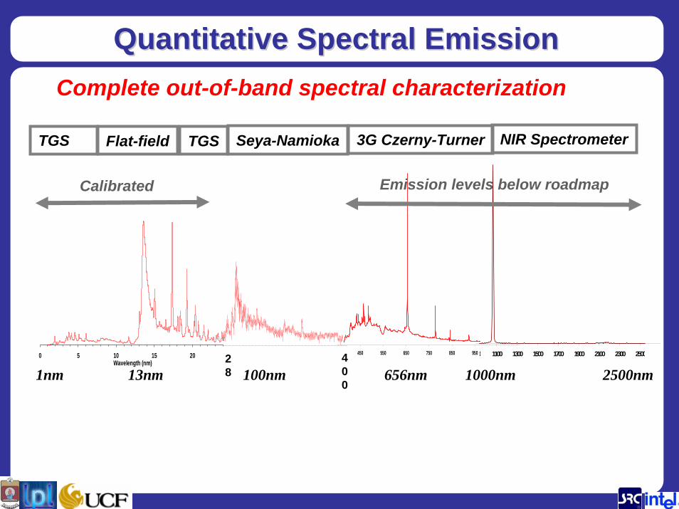
Quantitative Spectral EmissionQuantitative Spectral Emission
0 5 10 15 20Wavelength (nm)
0 1100 1300 1500 1700 1900 2100 2300 250028
400
450 550 650 750 850 950
1nm 13nm 100nm 656nm 1000nm 2500nm
TGS Flat-field TGS Seya-Namioka 3G Czerny-Turner NIR Spectrometer
Complete out-of-band spectral characterization
Emission levels below roadmapCalibrated
0.0E+00
5.0E+06
1.0E+07
1.5E+07
2.0E+07
100 1000 10000 100000
KE [eV]
dN/dE
O+
O2+
O3+
O4+
O5+
-0.06
-0.04
-0.02
0
0.02
0.0E+00 1.0E-05 2.0E-05 3.0E-05
TOF [s]
Sig
nal [
V]
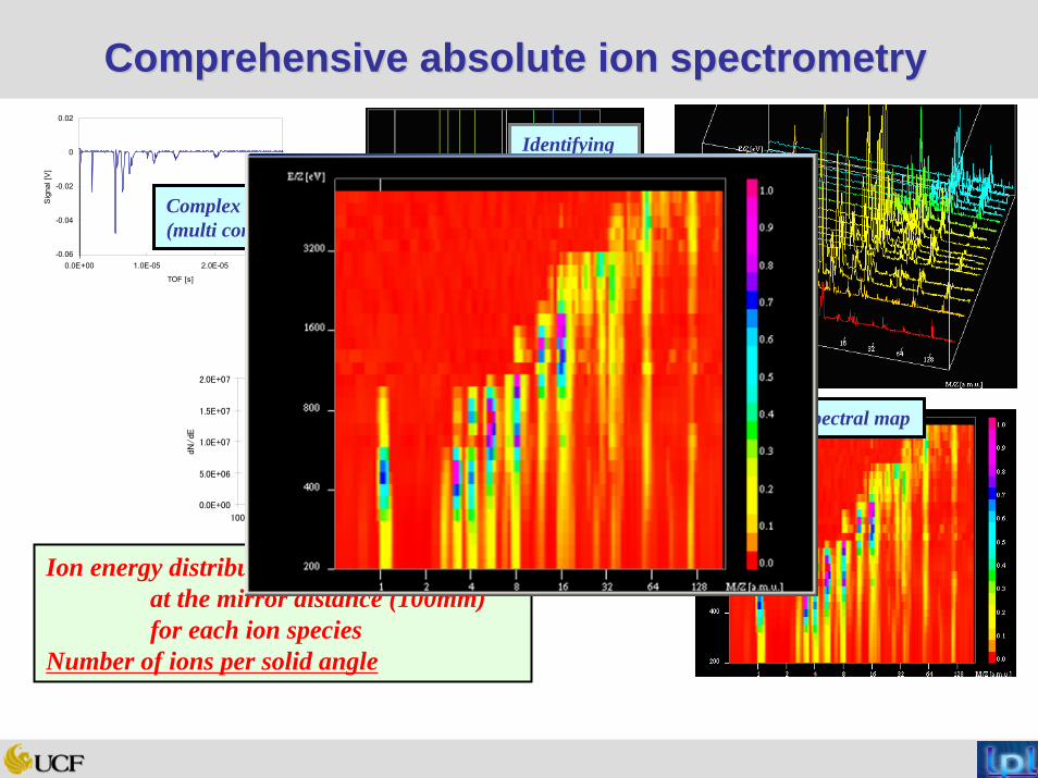
Comprehensive absolute ion spectrometryComprehensive absolute ion spectrometry
Complex signal (multi components)
Identifying all peaks
Entire spectral map
Ion energy distribution obtainedat the mirror distance (100mm)for each ion species
Number of ions per solid angle
Energy distributions
Conversion Repeat and sweeping analyzer voltage
Interpolation
Extracting for each ion species & counting charges
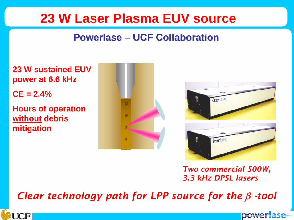
Clear technology path for LPP source for the β -tool
23 W Laser Plasma EUV sourcePowerlasePowerlase –– UCF CollaborationUCF Collaboration
Two commercial 500W, 3.3 kHz DPSL lasers
23 W sustained EUV power at 6.6 kHz
CE = 2.4%
Hours of operation without debris mitigation

Extension to HVM requirements Extension to HVM requirements
Current Power at Source 24 WTwo 500 W lasers Shooting 2 targets out of 10Current laser shot rate 6.6 kHzTarget rate 33 kHz
With 10 lasers Source Power = 120 WSource repetition rate… equals target rate = 33 kHz At least 30 W at IF
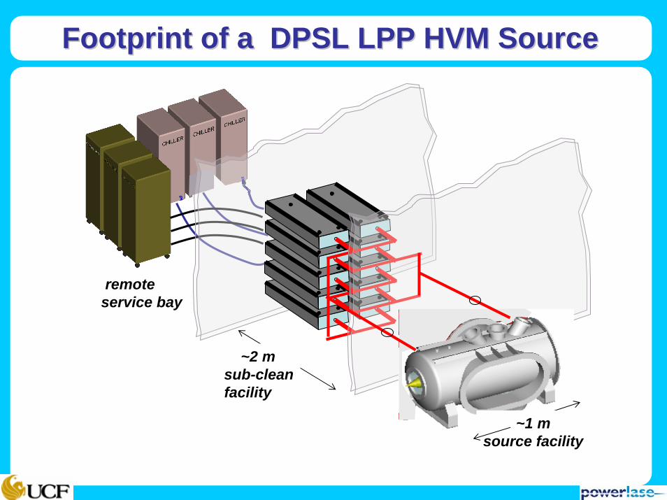
Footprint of a DPSL LPP HVM SourceFootprint of a DPSL LPP HVM Source
~2 msub-cleanfacility
~1 m source facility
remote service bay
Δn
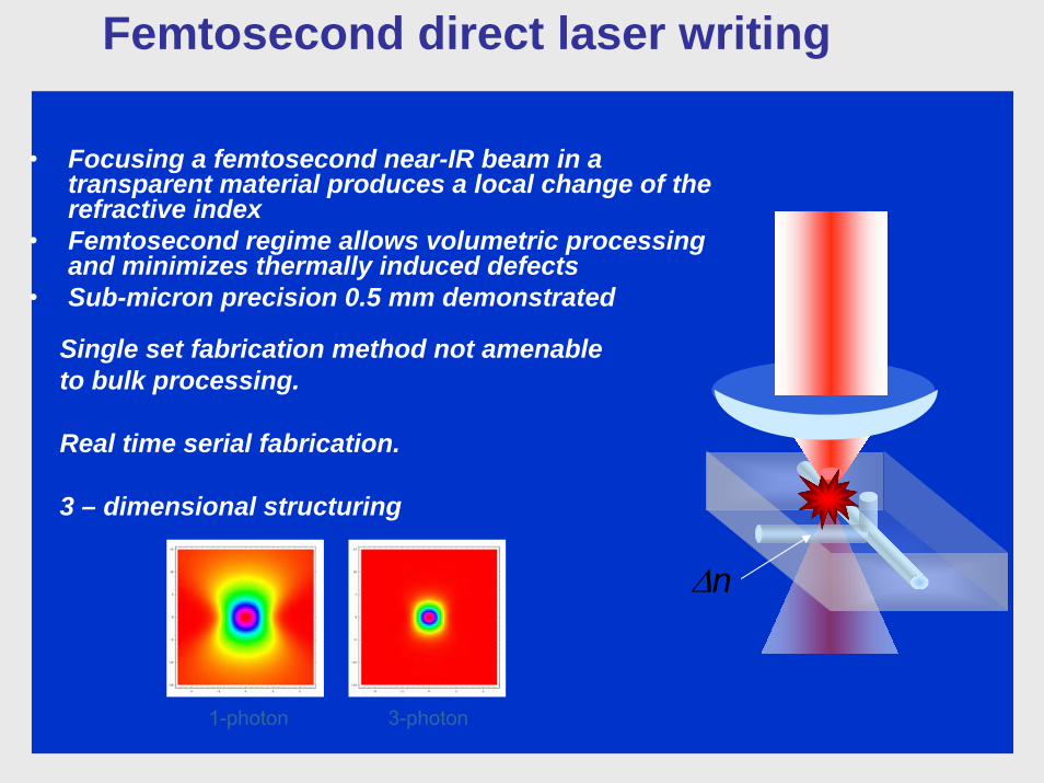
• Focusing a femtosecond near-IR beam in a transparent material produces a local change of the refractive index
• Femtosecond regime allows volumetric processing and minimizes thermally induced defects
• Sub-micron precision 0.5 mm demonstrated
Single set fabrication method not amenable to bulk processing.
Real time serial fabrication.
3 – dimensional structuring
Femtosecond direct laser writing
1-photon 3-photon

Just below plasma production…..
Surface profile (interferometer microscope)
Typical width ~10 μm (FWHM)
I = 40 GW/cm2 ~ 106 pulses
Λ = 20 μm
30 nm surface relief
I = 0.25 GW/cm2 ~ 106 pulses
Micro-ablation relief features Micro-restructuring of material
Photo-induced expansion
45 35 25 15 5I (GW/cm2)

Photo-chemical: bond changesPhoto-expansion: ΔV Photo-refraction: ΔnPhoto-darkening: ΔαIncrease in thermal conductivity: Δκ
As As
As
S
S
S
Fs pulseAsS
Free electron excitation leads to structural change
Conduction band
Valence band
Multiphotonabsorption
fs pulse
Avalanche absorption
ek
ke ntItIt
n )()( ασ +=∂
∂
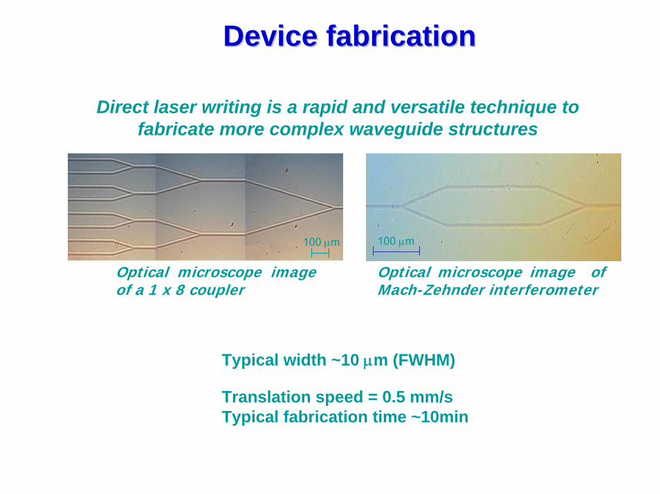
Direct laser writing is a rapid and versatile technique to fabricate more complex waveguide structures
Typical width ~10 μm (FWHM)
Translation speed = 0.5 mm/s Typical fabrication time ~10min
100 μm100 μm
Device fabricationDevice fabrication
Optical microscope image of a 1 x 8 coupler
Optical microscope image of Mach-Zehnder interferometer
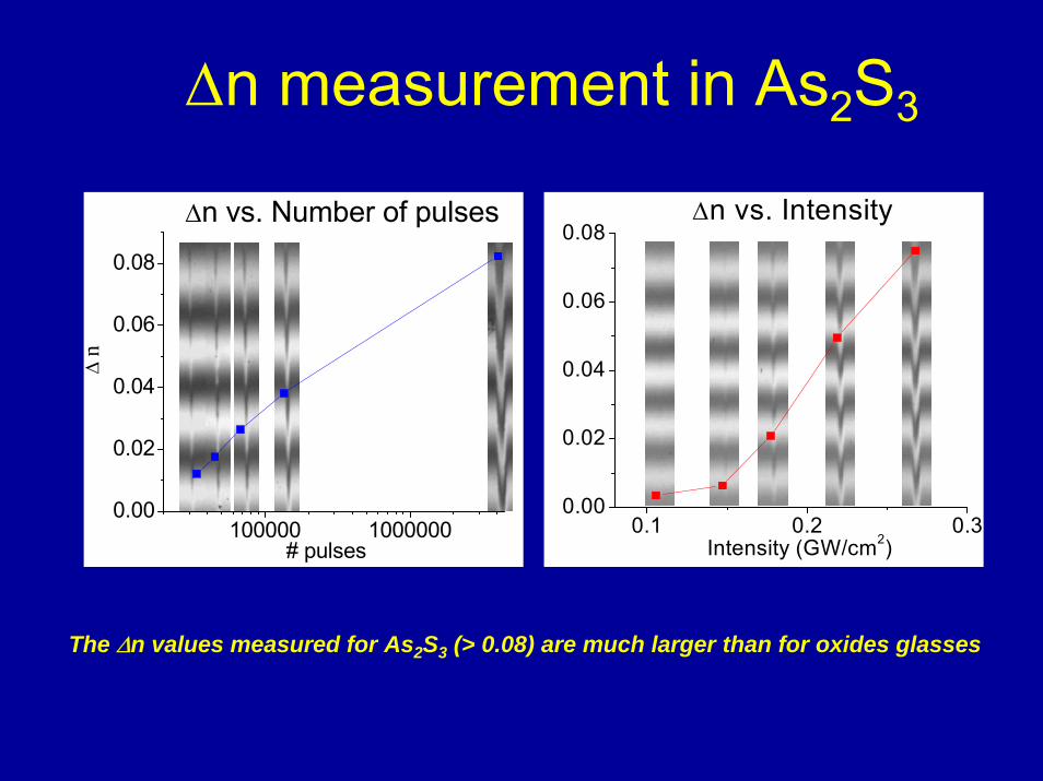
The Δn values measured for As2S3 (> 0.08) are much larger than for oxides glasses
Δn measurement in As2S3
0.1 0.2 0.30.00
0.02
0.04
0.06
0.08Δn vs. Intensity
Intensity (GW/cm2)100000 1000000
0.00
0.02
0.04
0.06
0.08
Δn vs. Number of pulses
Δ n
# pulses
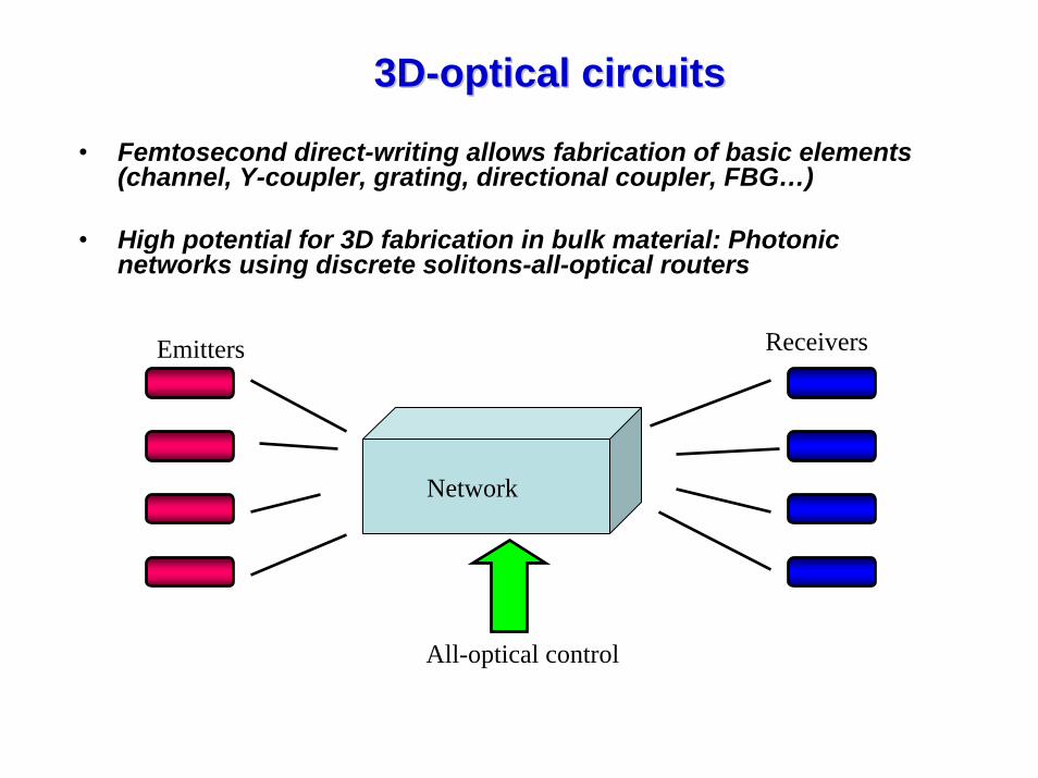
3D3D--optical circuitsoptical circuits
• Femtosecond direct-writing allows fabrication of basic elements (channel, Y-coupler, grating, directional coupler, FBG…)
• High potential for 3D fabrication in bulk material: Photonic networks using discrete solitons-all-optical routers
Emitters Receivers
All-optical control
Network

Discrete solitons in nonlinear waveguide arraysDiscrete solitons in nonlinear waveguide arrays
• From coupled-mode theory, the modal fields in a nonlinear waveguide array are governed by a discrete nonlinear Schroedinger equation
0)( 211 =+++ −+ nnnn
n EEEEcdz
dEi γ
linear coupling effectsbetween nearest neighbors
Nonlinear self-phase modulation effects in each waveguide
D. N. Christodoulides and R. I. Joseph, Optics Letters 13, 794 (1988)

Moving discrete solitonsMoving discrete solitons
-150 -100 -50 0 50 100 1500
1
2
X,
z = 0
z = 4.356 mmz = 8.57 mm
mμ
Discrete solitons move on predefined tracks and thus can be “navigated” in an optical network
Demitrios Christodoulides, George Stegeman

T = 96 %
T = 92 %T = 98 %
Blockers (strongly confined discrete solitons) can be used as control solitons for all-optical switching applications
Blocking discrete solitons at network junctionsBlocking discrete solitons at network junctionsBlocking discrete solitons at network junctions
E. D. Eugenieva, N. K. Efremidis and D. N. Christodoulides, Opt. Lett. 26, 1978 (2001)

X-ray microscopy of labeled live biological organisms with a nanosecond laser-plasma source
X-ray microscopy of labeled live biological organisms with a nanosecond laser-plasma source
10 μm
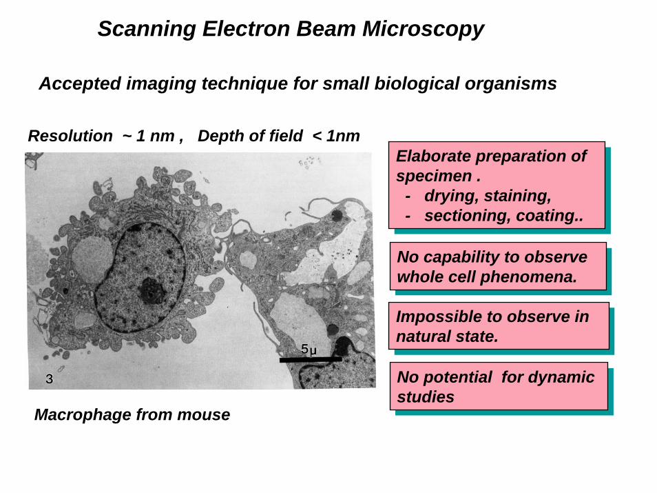
Scanning Electron Beam Microscopy
Macrophage from mouse
Resolution ~ 1 nm , Depth of field < 1nm Elaborate preparation of specimen .- drying, staining, - sectioning, coating..
Elaborate preparation of specimen .- drying, staining, - sectioning, coating..
No capability to observe whole cell phenomena.
No capability to observe whole cell phenomena.
Impossible to observe in natural state.
Impossible to observe in natural state.
No potential for dynamic studies
No potential for dynamic studies
Accepted imaging technique for small biological organisms
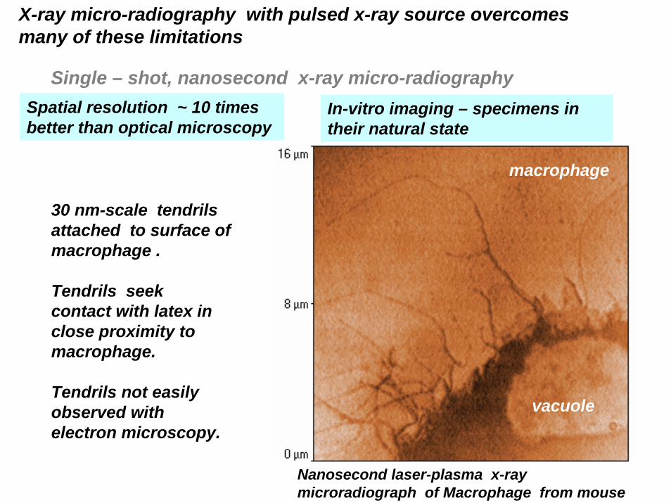
X-ray micro-radiography with pulsed x-ray source overcomes many of these limitations
30 nm-scale tendrils attached to surface of macrophage .
Tendrils seek contact with latex in close proximity to macrophage.
Tendrils not easily observed with electron microscopy.
tendrils
Nanosecond laser-plasma x-ray microradiograph of Macrophage from mouse
macrophage
vacuole
Single – shot, nanosecond x-ray micro-radiographySpatial resolution ~ 10 times better than optical microscopy
In-vitro imaging – specimens in their natural state
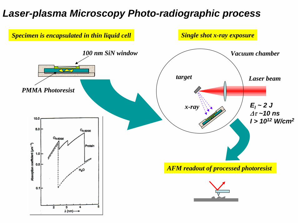
Specimen is encapsulated in thin liquid cell
100 nm SiN window
PMMA Photoresist
Single shot x-ray exposure
Vacuum chamber
Laser beamtarget
x-ray
AFM readout of processed photoresist
Laser-plasma Microscopy Photo-radiographic process
El ~ 2 JΔτ ~10 nsI > 1012 W/cm2
Unfixed Fixed
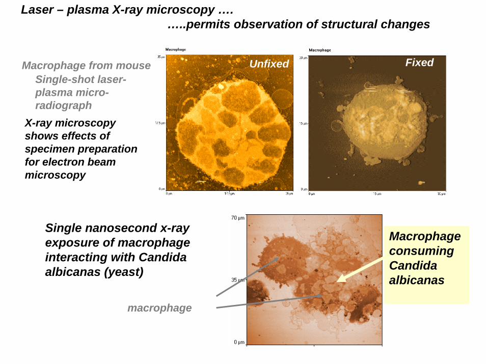
Laser – plasma X-ray microscopy ….…..permits observation of structural changes
Macrophage from mouse
X-ray microscopy shows effects of specimen preparation for electron beam microscopy
Single-shot laser-plasma micro-radiograph
Macrophage consuming Candida albicanas
Single nanosecond x-ray exposure of macrophage interacting with Candida albicanas (yeast)
macrophage
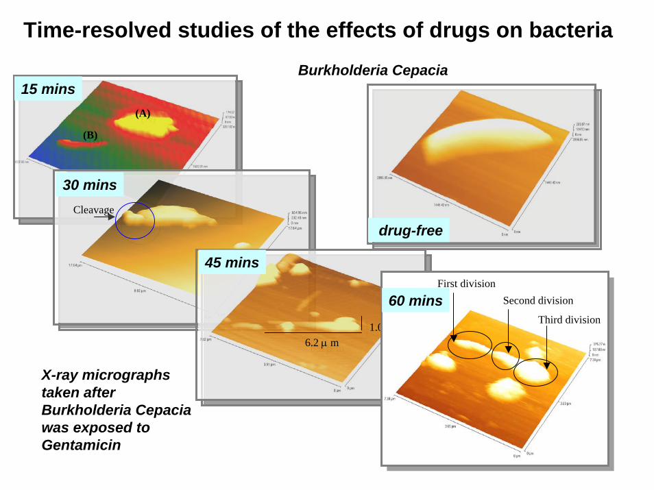
(A)
(B)
(A)
(B)
CleavageCleavage
6.2 μ m 1.0 μm
6.2 μ m 1.0 μm
Third division
Second divisionFirst division
Time-resolved studies of the effects of drugs on bacteriaBurkholderia Cepacia
30 mins
15 mins
45 mins
60 mins
drug-free
X-ray micrographs taken after Burkholderia Cepaciawas exposed to Gentamicin

Nano paticle doped Antibody
Antigen
Cell Membrane
Individual 18 nm goldnanoparticles
X-ray imaging of single cells – protein labeling
human lymphocytes
Optical imageX- ray image
Dr Ma’an Al- AniPhD -2001
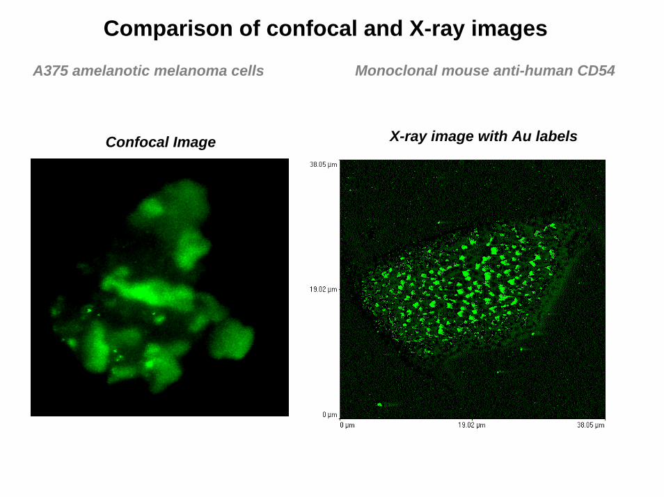
Confocal Image X-ray image with Au labels
Comparison of confocal and X-ray images
A375 amelanotic melanoma cells Monoclonal mouse anti-human CD54
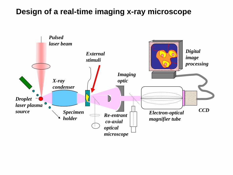
Pulsedlaser beam
Dropletlaser plasmasource
X-ray condenser
Specimenholder
External stimuli
Imaging optic
Electron-opticalmagnifier tube
CCD
Digitalimageprocessing
Re-entrantco-axial
opticalmicroscope
Design of a real-time imaging x-ray microscope

Fs high energy electron, x-ray, particle source
++++
+++
+ +
+
focused high intensity femtosecond laser radiation
multi- 100MG magnetic fields
relativistic electrons Collimated
beams of high energy protons
mVE
mWmVEI
mwfstmJU
/102
.10377
).(
10,100,100
11
220212
0
×=∴
==
==Δ=
−−
μ 30 μm
10 μm
35 μm
30kHz droplets
10 17 10 18 10 19 10 20 10 210,1
1
10
100
Tan
Gitomer
Fews
Beg
Maksimchuk
NemotoClark
Clark 2
HatchettSnavely
Mackinnon
Bell
Mori
Murakami
Spencer KrushelnickZepf
MBI 1kHz
Laser Intensity [Wµm²/cm²]
MBI 1kHz
Max
. pro
ton
ener
gy (M
eV)
Con
vers
ion
effic
ienc
y (%
age)
10
1
0.1
0.01
kHz
10 17 10 18 10 19 10 20 10 210,1
1
10
100
10 17 10 18 10 19 10 20 10 210,1
1
10
100
Tan
Gitomer
Fews
Beg
Maksimchuk
NemotoClark
Clark 2
HatchettSnavely
Mackinnon
Bell
Mori
Murakami
Spencer KrushelnickZepf
MBI 1kHz
Laser Intensity [Wµm²/cm²]
MBI 1kHz
Max
. pro
ton
ener
gy (M
eV)
Con
vers
ion
effic
ienc
y (%
age)
10
1
0.1
0.01
kHz
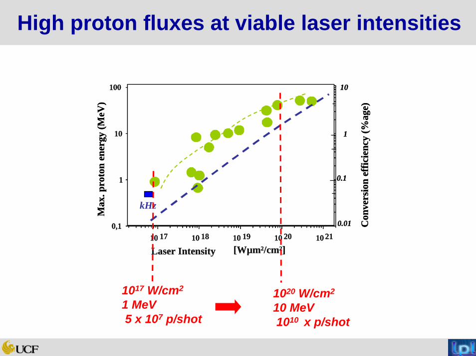
1017 W/cm2
1 MeV 5 x 10⁷ p/shot
1020 W/cm2
10 MeV 1010 x p/shot
High proton fluxes at viable laser intensities

Proton Therapy of Choroid Melanoma of the eye
• 50% of all proton cancer therapy
• 70 MeV - modulated
• 5 – 6 facilities worldwide
• Only alternatives –isotopes or removal
http://www.triumf.ca/welcome/proton
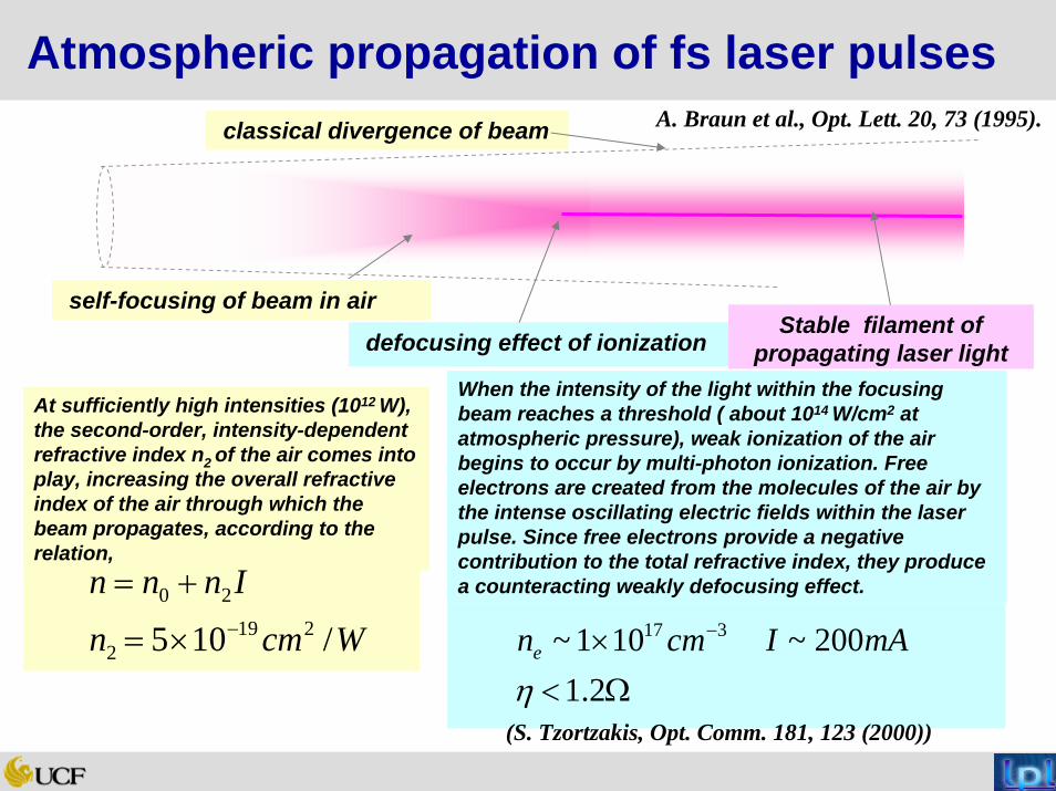
Atmospheric propagation of fs laser pulsesclassical divergence of beam
defocusing effect of ionizationStable filament of
propagating laser light
At sufficiently high intensities (1012 W), the second-order, intensity-dependent refractive index n2 of the air comes into play, increasing the overall refractive index of the air through which the beam propagates, according to the relation,
When the intensity of the light within the focusing beam reaches a threshold ( about 1014 W/cm2 at atmospheric pressure), weak ionization of the air begins to occur by multi-photon ionization. Free electrons are created from the molecules of the air by the intense oscillating electric fields within the laser pulse. Since free electrons provide a negative contribution to the total refractive index, they produce a counteracting weakly defocusing effect.
A. Braun et al., Opt. Lett. 20, 73 (1995).
Wcmn
Innn
/105 2192
20−×=
+=
self-focusing of beam in air
Ω<× −
2.1200~101~ 317
ηmAIcmne
(S. Tzortzakis, Opt. Comm. 181, 123 (2000))
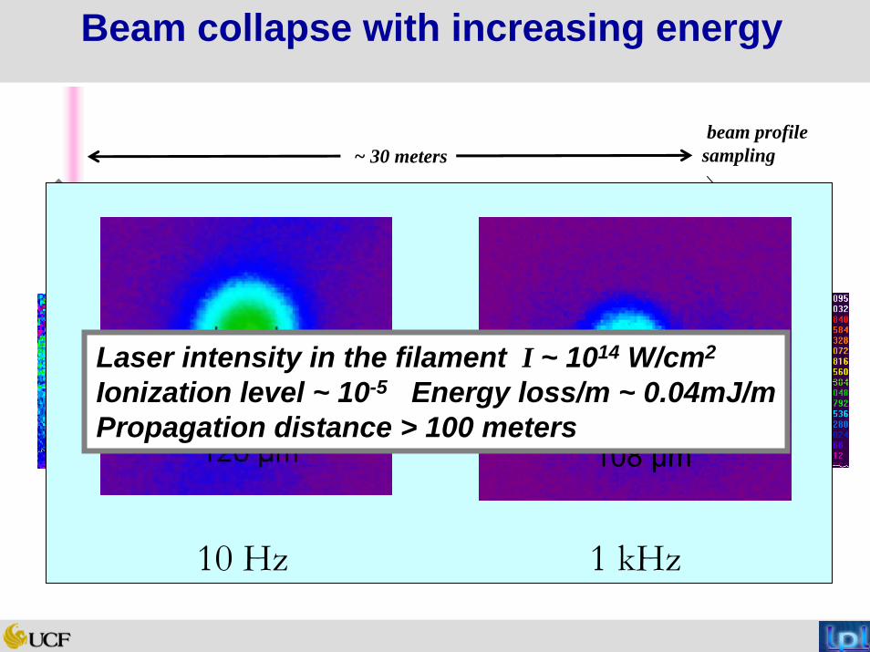
3 mJ 6 mJ 10 mJ 14 mJ
beam profile sampling~ 30 meters
Beam collapse with increasing energy
Spiricon
108 μm
10 Hz 1 kHz
Laser intensity in the filament I ~ 1014 W/cm2
Ionization level ~ 10-5 Energy loss/m ~ 0.04mJ/mPropagation distance > 100 meters
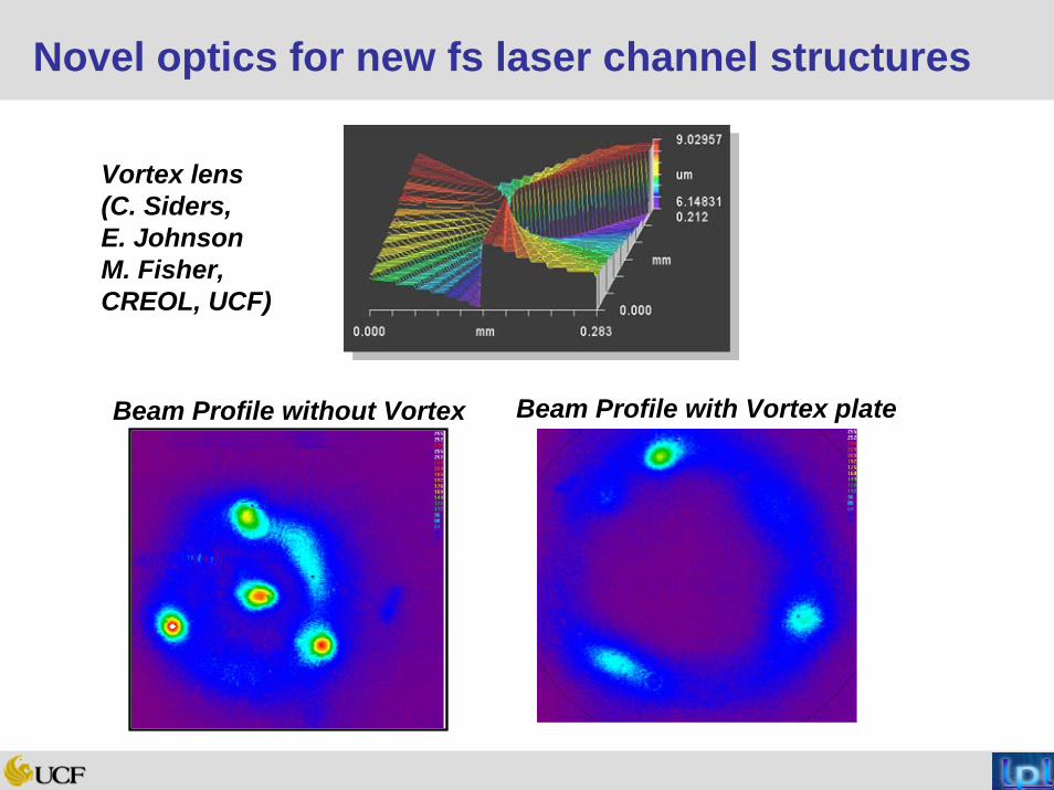
Novel optics for new fs laser channel structures
Beam Profile without Vortex Beam Profile with Vortex plate
Vortex lens(C. Siders,E. JohnsonM. Fisher, CREOL, UCF)
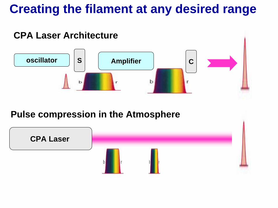
CPA Laser Architecture
oscillator S Amplifier C
CPA Laser
Pulse compression in the Atmosphere
Creating the filament at any desired range
R. Rairoux, et al., Appl . Phys. B 71 573 ( 2000)
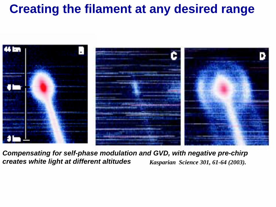
Creating the filament at any desired range
Compensating for self-phase modulation and GVD, with negative pre-chirp creates white light at different altitudes Kasparian Science 301, 61-64 (2003).

“Defying diffraction – High intensity femtosecond laser propagation through the atmosphere”. M. Richardson et al. Presented at PQE Conference, Snowbird, UT, Jan 7, 2004
Laser Plasma Laboratory School of Optics / CREOL
Unique propagation characteristicsUnique propagation characteristics…………
R Rairoux et al., Appl. Phys B 71,573 (2000)
Kasparian etal., Opt. Lett. 25, 1397 (2000)
300 μm Richardson et al CLEO 2003
The self-channeled beams can be extremely circular
The white light continuum extends from the atmospheric UV cut-off to the mid-IR

“Defying diffraction – High intensity femtosecond laser propagation through the atmosphere”. M. Richardson et al. Presented at PQE Conference, Snowbird, UT, Jan 7, 2004
Laser Plasma Laboratory School of Optics / CREOL
White light absorption spectroscopy LIDAR White light absorption spectroscopy LIDAR
Atmospheric transmission in the vis – IR R. Rairoux et alAppl. Phys. B 71, 573 (2000)
550-1050 m 150-1050 m 600-850 m 550-1100 m
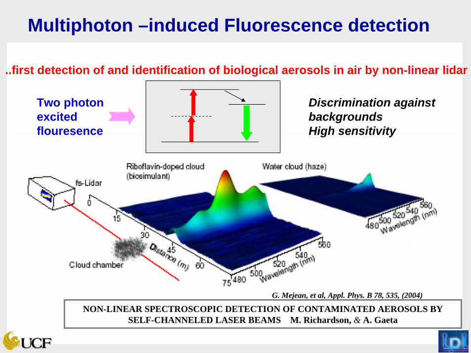
Multiphoton –induced Fluorescence detection
G. Mejean, et al, Appl. Phys. B 78, 535, (2004)
Two photon excited flouresence
..first detection of and identification of biological aerosols in air by non-linear lidar
Discrimination against backgroundsHigh sensitivity
NON-LINEAR SPECTROSCOPIC DETECTION OF CONTAMINATED AEROSOLS BY SELF-CHANNELED LASER BEAMS M. Richardson, & A. Gaeta

Interaction with AerosolsSelf-focusing of laser beam inside droplet.Microscopic plasma formation. Temperatures in excess of 7000 deg predicted White light emission dominated by LIB emission
Na D lines from saline solution droplet
Strong angle dependence of white light backscattered emission
C. Favre, et al, Phy. Rev. Lett. 89, 035002-1, (2002)
“Propagation & interaction studies of high intensity fs laser beams in the atmosphere” M. Richardson et al., NTAR VI –Nov.15-17, 2004 NTIC
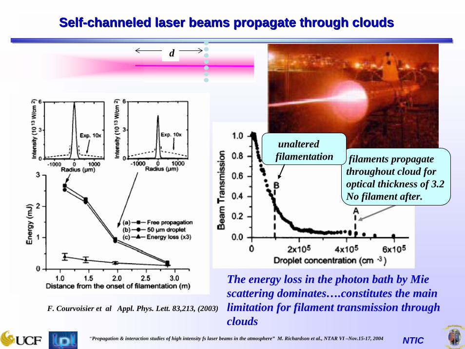
SelfSelf--channeled laser beams propagate through cloudschanneled laser beams propagate through clouds
F. Courvoisier et al Appl. Phys. Lett. 83,213, (2003)
The energy loss in the photon bath by Mie scattering dominates….constitutes the main limitation for filament transmission through clouds
d
filaments propagate throughout cloud for optical thickness of 3.2 No filament after.
unaltered filamentation

“Propagation & interaction studies of high intensity fs laser beams in the atmosphere” M. Richardson et al., NTAR VI –Nov.15-17, 2004 NTIC
Remote Remote LIBsLIBs with fs channelingwith fs channeling
fs laser
spectrometer
Kamil Stelmaszczyk, et al Appl. Phys Lett. (to be published)
R-LIBS at 1 km possible!

TNT Spectrum In Argon (Shot 1)
-500
0
500
1000
1500
2000
2500
3000
200 300 400 500 600 700 800 900
Wavelength (nm)
Military Grade TNT
3000
2500
2000
1500
1000
500
0200 300 400 500 600 700 800 900
Wavelength (nm)
I (a.
u.)
C - 247.8 nm O – 777.54 nm
O – 844.64 nm
CN Violet System-388.34 nm
C2 Swan System-516.52 nm
Ar
ArAr
Ar
ArAr
New LIBS data for TNT
Single Pulse Nanosecond LIBS, 1064 nm, 100 mJ/pulseArgon atmosphere
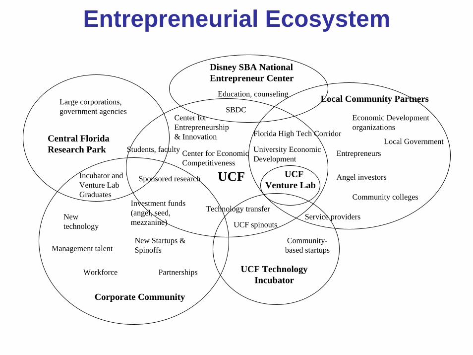
Corporate Community
UCF
Central Florida Research Park
Local Community Partners
New technology
Management talentNew Startups & Spinoffs
Partnerships
Students, faculty
Large corporations, government agencies
Center for Entrepreneurship & Innovation
Sponsored research UCFVenture Lab
University Economic Development
Investment funds (angel, seed, mezzanine)
Local Government
Economic Development organizations
Community colleges
Florida High Tech Corridor
UCF Technology Incubator
Community-based startups
UCF spinouts
Disney SBA National Entrepreneur Center
SBDC
Technology transferService providers
Angel investors
Education, counseling
Entrepreneurs
Workforce
Incubator and Venture Lab Graduates
Center for Economic Competitiveness
Entrepreneurial Ecosystem
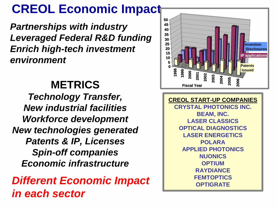
CREOL Economic ImpactPartnerships with industryLeveraged Federal R&D fundingEnrich high-tech investment environment
METRICSTechnology Transfer,
New industrial facilitiesWorkforce development
New technologies generatedPatents & IP, Licenses
Spin-off companiesEconomic infrastructure
1998
1999
2000
2001
2002
2003
2004
2005
2006
05
101520253035404550
Fiscal Year
IP applications
InventionDisclosures
PatentsIssued
1998
1999
2000
2001
2002
2003
2004
2005
2006
05
101520253035404550
Fiscal Year
IP applications
InventionDisclosures
PatentsIssued
CREOL START-UP COMPANIESCRYSTAL PHOTONICS INC.
BEAM, INC.LASER CLASSICS
OPTICAL DIAGNOSTICSLASER ENERGETICS
POLARAAPPLIED PHOTONICS
NUONICSOPTIUM
RAYDIANCEFEMTOPTICSOPTIGRATEDifferent Economic Impact
in each sector

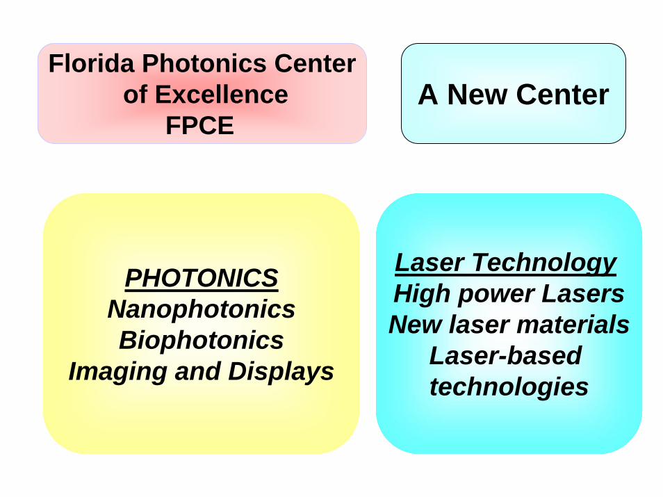
Florida Photonics Centerof Excellence
FPCE
PHOTONICSNanophotonicsBiophotonics
Imaging and Displays
Laser Technology High power LasersNew laser materials
Laser-based technologies
A New Center
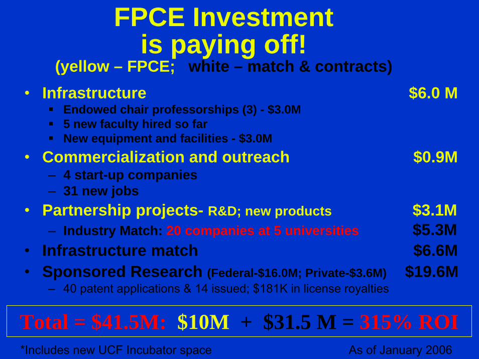
FPCE Investmentis paying off!
(yellow – FPCE; white – match & contracts)• Infrastructure $6.0 M
Endowed chair professorships (3) - $3.0M5 new faculty hired so farNew equipment and facilities - $3.0M
• Commercialization and outreach $0.9M – 4 start-up companies– 31 new jobs
• Partnership projects- R&D; new products $3.1M– Industry Match: 20 companies at 5 universities $5.3M
• Infrastructure match $6.6M• Sponsored Research (Federal-$16.0M; Private-$3.6M) $19.6M
– 40 patent applications & 14 issued; $181K in license royalties
Total = $41.5M: $10M + $31.5 M = 315% ROIAs of January 2006*Includes new UCF Incubator space
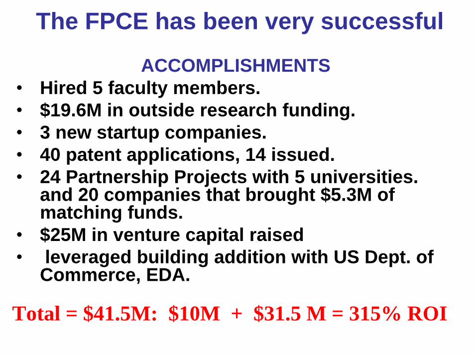
The FPCE has been very successful
ACCOMPLISHMENTS• Hired 5 faculty members. • $19.6M in outside research funding. • 3 new startup companies.• 40 patent applications, 14 issued.• 24 Partnership Projects with 5 universities.
and 20 companies that brought $5.3M of matching funds.
• $25M in venture capital raised• leveraged building addition with US Dept. of
Commerce, EDA.
Total = $41.5M: $10M + $31.5 M = 315% ROI
Florida Photonics Centerof Excellence
FPCE
PHOTONICSNanophotonicsBiophotonics
Imaging and Displays
Laser Technology High power LasersNew laser materials
Laser-based technologies
A New Center
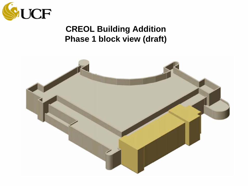
CREOL Building Addition Phase 1 block view (draft)
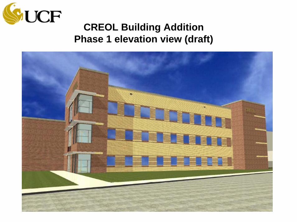
CREOL Building AdditionPhase 1 elevation view (draft)

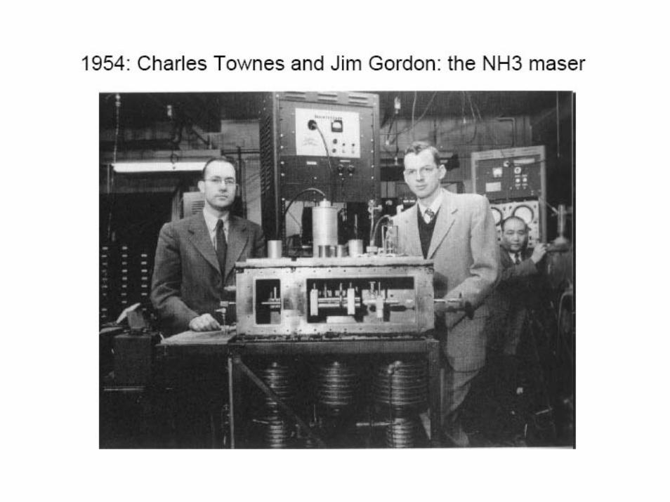
Nobel Prize 1964Nobel Prize 1964 Templeton Prize 2005Templeton Prize 2005
A laser center named after Charles Townes – the inventor of the Laser
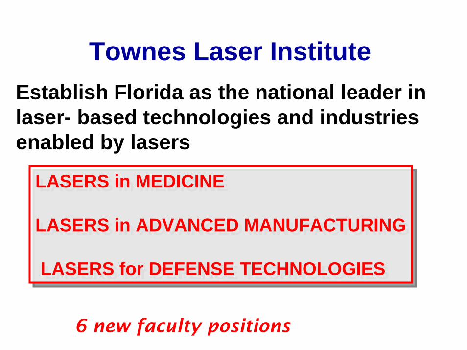
LASERS in MEDICINE
LASERS in ADVANCED MANUFACTURING
LASERS for DEFENSE TECHNOLOGIES
LASERS in MEDICINE
LASERS in ADVANCED MANUFACTURING
LASERS for DEFENSE TECHNOLOGIES
Establish Florida as the national leader in laser- based technologies and industries enabled by lasers
6 new faculty positions
Townes Laser Institute

Charles Townes (and Mrs Townes) - 2006