Embed Size (px)
Citation preview
Name___________________________________ Date: ________________ Course number: _________________ MAKE SURE TA & TI STAMPS EVERY PAGE BEFORE YOU START
TA or TI Signature ___________________________________ 1 of 17
Laboratory Section: ____________ Partners’ Names: __________________________ Last Revised on January 8, 2015 Grade: ___________________________
EXPERIMENT 5
The Equivalence of Energy: Heat, Mechanical, Electrical, and
Light 0. Pre-Laboratory Work [2pts] 1. A 90kg person jumps from a 30m tower into a tub of water with a volume of 5m3 initially at
20°C. Assuming that all of the work done by the person is converted into heat to the water, what is the final temperature of the water? It’s helpful to first find the work done by the person to the water tub and then the amount of heat equivalent to that work. Make sure you have the correct value for the mass of the water. Include units. [1pt]
2. In both Section 3.1 and Section 3.2.1 you are asked to continue taking temperature
measurements even after the heat source has been turned off. What effect are we trying to observe and how do we use this effect in our data analysis? [1pt]
Name___________________________________ Date: ________________ Course number: _________________ MAKE SURE TA & TI STAMPS EVERY PAGE BEFORE YOU START
TA or TI Signature ___________________________________ 2 of 17
Last Revised on January 8, 2015
EXPERIMENT 5
The Equivalence of Energy: Heat, Mechanical, Electrical, and
Light 1. Purpose
The purpose is to observe the conversion of energy from one form to another. In part Ι , you will measure the proportional relationship of mechanical work to heat, a relationship governed by Joule’s constant [4.18 J/cal (Joules per calorie)]. In part ΙΙ , you will use a light bulb to convert electrical energy into either heat, from which you will again determine Joule’s constant, or you will convert electrical energy into heat and light, allowing the light energy from the light bulb to escape. (Your TA will assign you to one of these two experiments in part II.). By comparing your results with another group, you will be able to calculate the efficiency of the conversion of electrical energy to light.
In summary, you will do the following: Ι . Conversion of Mechanical Energy into Heat ΙΙ . Conversion of Electrical Energy
1. Conversion of Electrical Energy into Heat 2. Conversion of Electrical Energy into Heat and Light
2. Introduction
One of the most fundamental principles of physics is the conservation of energy. According to this principle, energy cannot be created or destroyed but may only be transformed from one form to another. An early application of this principle was used to explain the conversion of work to heat by Joule. This was soon extended to other experiments such as the conversion of electrical energy to work, heat, or light. Einstein’s famous equation 2mcE = is an application of this principle. So strong is this principle that in 1931 Pauli confidently predicted based on the energy conservation the existence of a massless particle—the neutrino—to explain certain experiments. Direct confirmation was not obtained until 1953!
2.1 Conversion of Mechanical Energy into Heat
Name___________________________________ Date: ________________ Course number: _________________ MAKE SURE TA & TI STAMPS EVERY PAGE BEFORE YOU START
TA or TI Signature ___________________________________ 3 of 17
A common experience with friction is direct evidence for a relation between mechanical
and thermal energies. When two rough objects are rubbed together they tend to warm up. Consider, for example, two hands on a cold Rochester morning or two dry sticks in the care of a skillful Scout.
Joule noticed this fact and conjectured that the mechanical work W done in rubbing is directly proportional to the quantity of heat QΔ produced,
QJW MechanicalΔ= , Equation 5.1 where MechanicalJ is Joule’s constant of proportionality for mechanical energy. Joule devised elegant experiments that confirmed this relationship. He also showed that W could be any form of energy, not just work against friction, provided it is all converted to heat.
In this experiment you will recreate one of Joule’s experiments involving friction. Mechanical work W is the product of a force times the distance through which it acts. How can one measure heat? A body’s state is changed when heat is added. For instance, its temperature may rise or there may be a phase change (e.g., from solid to liquid or liquid to gas). As long as the temperature change is small and no change of phase occurs, the heat QΔ into a body is directly proportional to the change in its temperature, to a first approximation. Furthermore, since a body can be (conceptually) broken up into smaller ones and the heat into the whole is the sum of the heat into the parts, a given temperature change should require an amount of heat directly proportional to the mass. Therefore, the heat QΔ into the body is
( )if TTmCTmCQ −=Δ=Δ , Equation 5.2 where m is the mass of the body, and iT and fT are the initial and final temperatures, respectively. The constant of proportionality C , called the specific heat, relates the temperature change of the body to the quantity of heat that causes it. The specific heat is a characteristic of the material of which the body is composed. This relationship that C is independent of temperature is an approximation that is good over small temperature changes.
The CGS (centimeters, grams, seconds) unit of heat is a calorie and defined as the quantity of heat required to raise the temperature of one gram (g) of water from 14.5°C to 15.5°C. Hence, by definition, water has a specific heat of 1 cal/g°C over that range of temperature. The specific heats of other materials are determined by comparing with that of water and are tabulated for many common materials. For instance, the accepted value of the
specific heat of brass is Cgcal0925.0 =BC , which you will need in analyzing your
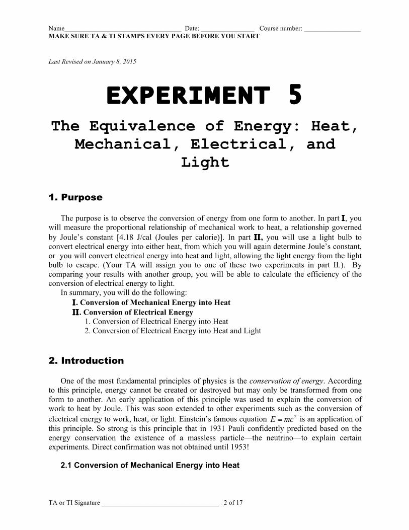
experiment. In this experiment there are two brass pieces, held stationary by a string, and one plastic
disk, which is positioned between the two brass pieces and rotated by a hand crank. As the plastic disk rotates, it rubs against the brass pieces creating heat, while the tension of the string prevents the brass pieces from moving. The force of cranking is countered by the friction with the brass pieces rather than accelerating the plastic disk, and so the work put into the system generates heat (via the friction) instead of mechanical energy.(See Figure 5.1.)
Figure 5.1
Name___________________________________ Date: ________________ Course number: _________________ MAKE SURE TA & TI STAMPS EVERY PAGE BEFORE YOU START
TA or TI Signature ___________________________________ 4 of 17
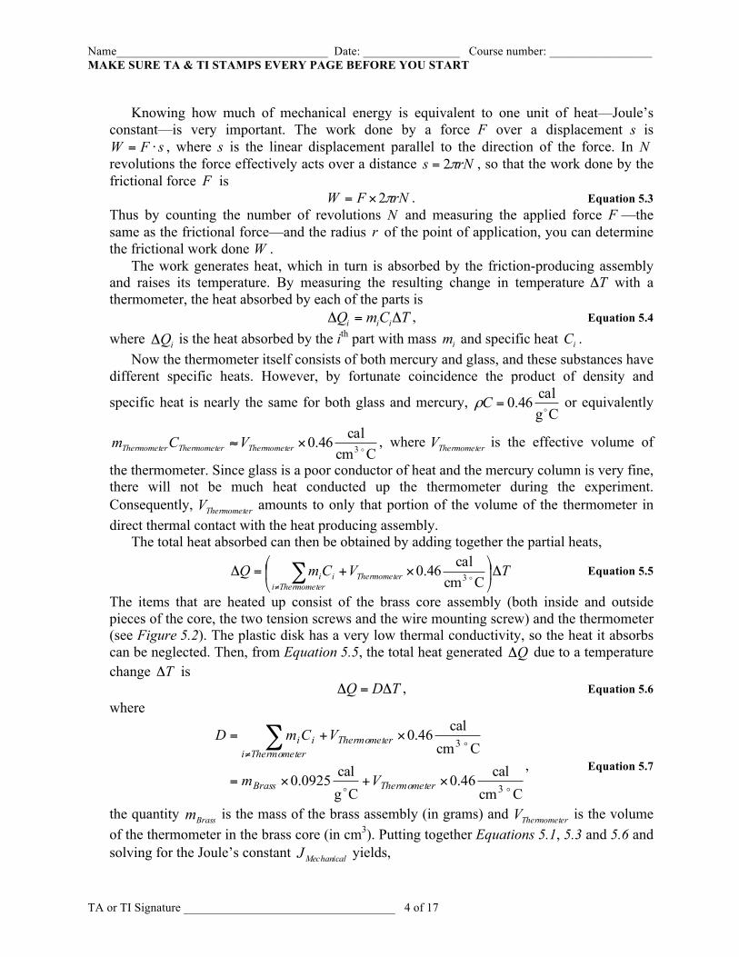
Knowing how much of mechanical energy is equivalent to one unit of heat—Joule’s
constant—is very important. The work done by a force F over a displacement s is sFW ⋅= , where s is the linear displacement parallel to the direction of the force. In N
revolutions the force effectively acts over a distance rNs π2= , so that the work done by the frictional force F is
rNFW π2×= . Equation 5.3 Thus by counting the number of revolutions N and measuring the applied force F —the same as the frictional force—and the radius r of the point of application, you can determine the frictional work done W .
The work generates heat, which in turn is absorbed by the friction-producing assembly and raises its temperature. By measuring the resulting change in temperature TΔ with a thermometer, the heat absorbed by each of the parts is
TCmQ iii Δ=Δ , Equation 5.4 where iQΔ is the heat absorbed by the ith part with mass im and specific heat iC .
Now the thermometer itself consists of both mercury and glass, and these substances have different specific heats. However, by fortunate coincidence the product of density and
specific heat is nearly the same for both glass and mercury, Cgcal46.0 =Cρ or equivalently
Ccmcal46.0 3 ×≈ rThermometerThermometerThermomete VCm , where rThermometeV is the effective volume of
the thermometer. Since glass is a poor conductor of heat and the mercury column is very fine, there will not be much heat conducted up the thermometer during the experiment. Consequently, rThermometeV amounts to only that portion of the volume of the thermometer in direct thermal contact with the heat producing assembly.
The total heat absorbed can then be obtained by adding together the partial heats,
TVCmQ rThermometerThermometeiii Δ⎟
⎠
⎞⎜⎝
⎛×+=Δ ∑
≠ Ccmcal46.0 3 Equation 5.5
The items that are heated up consist of the brass core assembly (both inside and outside pieces of the core, the two tension screws and the wire mounting screw) and the thermometer (see Figure 5.2). The plastic disk has a very low thermal conductivity, so the heat it absorbs can be neglected. Then, from Equation 5.5, the total heat generated QΔ due to a temperature change TΔ is
TDQ Δ=Δ , Equation 5.6 where
Ccmcal46.0
Cgcal0925.0
Ccmcal46.0
3
3
×+×=
×+= ∑≠
rThermometeBrass
rThermometerThermometeiii
Vm
VCmD
, Equation 5.7
the quantity Brassm is the mass of the brass assembly (in grams) and rThermometeV is the volume of the thermometer in the brass core (in cm3). Putting together Equations 5.1, 5.3 and 5.6 and solving for the Joule’s constant MechanicalJ yields,
Name___________________________________ Date: ________________ Course number: _________________ MAKE SURE TA & TI STAMPS EVERY PAGE BEFORE YOU START
TA or TI Signature ___________________________________ 5 of 17
TDrNF
QWJMechanical Δ
=Δ
=π2 . Equation 5.8
2.2 Conversion of Electrical Energy
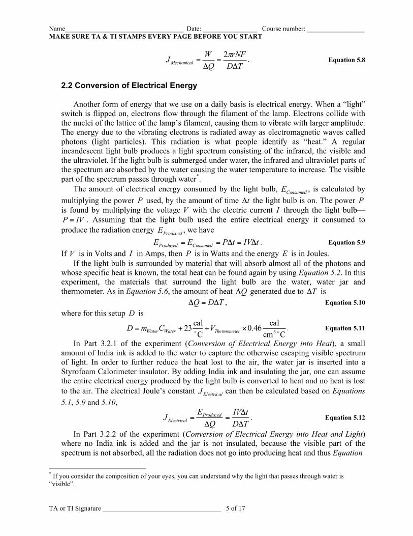
Another form of energy that we use on a daily basis is electrical energy. When a “light”
switch is flipped on, electrons flow through the filament of the lamp. Electrons collide with the nuclei of the lattice of the lamp’s filament, causing them to vibrate with larger amplitude. The energy due to the vibrating electrons is radiated away as electromagnetic waves called photons (light particles). This radiation is what people identify as “heat.” A regular incandescent light bulb produces a light spectrum consisting of the infrared, the visible and the ultraviolet. If the light bulb is submerged under water, the infrared and ultraviolet parts of the spectrum are absorbed by the water causing the water temperature to increase. The visible part of the spectrum passes through water*.
The amount of electrical energy consumed by the light bulb, ConsumedE , is calculated by multiplying the power P used, by the amount of time tΔ the light bulb is on. The power P is found by multiplying the voltage V with the electric current I through the light bulb—
IVP = . Assuming that the light bulb used the entire electrical energy it consumed to produce the radiation energy ProducedE , we have
tIVtPEE ConsumedProduced Δ=Δ== . Equation 5.9 If V is in Volts and I in Amps, then P is in Watts and the energy E is in Joules.
If the light bulb is surrounded by material that will absorb almost all of the photons and whose specific heat is known, the total heat can be found again by using Equation 5.2. In this experiment, the materials that surround the light bulb are the water, water jar and thermometer. As in Equation 5.6, the amount of heat QΔ generated due to TΔ is
TDQ Δ=Δ , Equation 5.10 where for this setup D is
Ccm
cal46.0Ccal23 3 ×++= rThermometeWaterWater VCmD . Equation 5.11
In Part 3.2.1 of the experiment (Conversion of Electrical Energy into Heat), a small amount of India ink is added to the water to capture the otherwise escaping visible spectrum of light. In order to further reduce the heat lost to the air, the water jar is inserted into a Styrofoam Calorimeter insulator. By adding India ink and insulating the jar, one can assume the entire electrical energy produced by the light bulb is converted to heat and no heat is lost to the air. The electrical Joule’s constant ElectricalJ can then be calculated based on Equations 5.1, 5.9 and 5.10,
TDtIV
QEJ Produced
Electrical ΔΔ
=Δ
= . Equation 5.12
In Part 3.2.2 of the experiment (Conversion of Electrical Energy into Heat and Light) where no India ink is added and the jar is not insulated, because the visible part of the spectrum is not absorbed, all the radiation does not go into producing heat and thus Equation
* If you consider the composition of your eyes, you can understand why the light that passes through water is “visible”.
Name___________________________________ Date: ________________ Course number: _________________ MAKE SURE TA & TI STAMPS EVERY PAGE BEFORE YOU START
TA or TI Signature ___________________________________ 6 of 17
5.12 is not applicable in this case. However, the visible light producing efficiency can be calculated from the following,
Produced
AbsorbedProduced
Produced
htVisibleLig
EEE
EE
−=
=Efficiency ProducingLight Visible, Equation 5.13
where htVisibleLigE is the energy of the visible light and AbsorbedE is the radiation energy absorbed by the water. Since the absorbed radiation energy AbsorbedE is the heat absorbed by the water, AbsorbedE can be calculated according to
QJEAbsorbed Δ= . Equation 5.14
where calJ19.4=J is the accepted value of Joule’s constant. The amount of heat QΔ
transferred to the water must be found using Equations 5.10 and 5.11. 3. Laboratory Work
3.1 Conversion of Mechanical Energy into Heat
Introduction In this experiment you will convert mechanical energy into heat. The mechanical energy
will produce friction, which in turn will generate heat. The heat will be observed by measuring the increase in temperature of known masses with known specific heat capacity.
Instructions for Mechanical Equivalence Apparatus
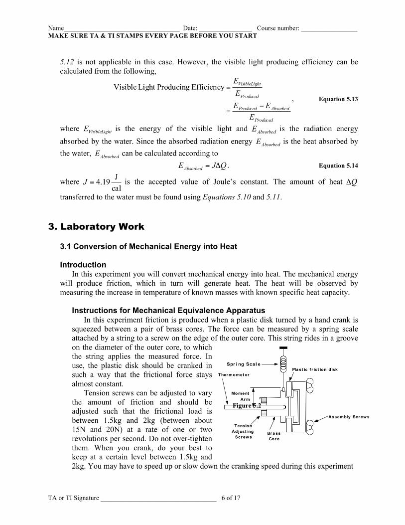
In this experiment friction is produced when a plastic disk turned by a hand crank is squeezed between a pair of brass cores. The force can be measured by a spring scale attached by a string to a screw on the edge of the outer core. This string rides in a groove on the diameter of the outer core, to which the string applies the measured force. In use, the plastic disk should be cranked in such a way that the frictional force stays almost constant.
Tension screws can be adjusted to vary the amount of friction and should be adjusted such that the frictional load is between 1.5kg and 2kg (between about 15N and 20N) at a rate of one or two revolutions per second. Do not over-tighten them. When you crank, do your best to keep at a certain level between 1.5kg and 2kg. You may have to speed up or slow down the cranking speed during this experiment
P l a s t i c f r i c t i o n d i s k
r M o m e n t
A r m
S p r i n g S c a l e
T e n s i o n A d j u s t i n g
S c r e w s
T h e r m o m e t e r
B r a s s C o r e
A s s e m b l y S c r e w s
Figure 5.2
Name___________________________________ Date: ________________ Course number: _________________ MAKE SURE TA & TI STAMPS EVERY PAGE BEFORE YOU START
TA or TI Signature ___________________________________ 7 of 17
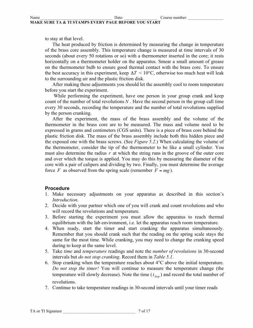
to stay at that level.
The heat produced by friction is determined by measuring the change in temperature of the brass core assembly. This temperature change is measured at time intervals of 30 seconds (about every 50 rotations or so) with a thermometer inserted in the core; it rests horizontally on a thermometer holder on the apparatus. Smear a small amount of grease on the thermometer bulb to ensure good thermal contact with the brass core. To ensure the best accuracy in this experiment, keep TΔ < 10°C, otherwise too much heat will leak to the surrounding air and the plastic friction disk.
After making these adjustments you should let the assembly cool to room temperature before you start the experiment.
While performing the experiment, have one person in your group crank and keep count of the number of total revolutionsN . Have the second person in the group call time every 30 seconds, recording the temperature and the number of total revolutions supplied by the person cranking.
After the experiment, the mass of the brass assembly and the volume of the thermometer in the brass core are to be measured. The mass and volume need to be expressed in grams and centimeters (CGS units). There is a piece of brass core behind the plastic friction disk. The mass of the brass assembly include both this hidden piece and the exposed one with the brass screws. (See Figure 5.2.) When calculating the volume of the thermometer, consider the tip of the thermometer to be like a small cylinder. You must also determine the radius r at which the string runs in the groove of the outer core and over which the torque is applied. You may do this by measuring the diameter of the core with a pair of calipers and dividing by two. Finally, you must determine the average force F as observed from the spring scale (remember mgF = ).
Procedure 1. Make necessary adjustments on your apparatus as described in this section’s
Introduction. 2. Decide with your partner which one of you will crank and count revolutions and who
will record the revolutions and temperature. 3. Before starting the experiment you must allow the apparatus to reach thermal
equilibrium with the lab environment, i.e. let the apparatus reach room temperature. 4. When ready, start the timer and start cranking the apparatus simultaneously.
Remember that you should crank such that the reading on the spring scale stays the same for the most time. While cranking, you may need to change the cranking speed during to keep at the same level.
5. Take time and temperature readings and note the number of revolutions in 30-second intervals but do not stop cranking. Record them in Table 5.1.
6. Stop cranking when the temperature reaches about 4°C above the initial temperature. Do not stop the timer! You will continue to measure the temperature change (the temperature will slowly decrease). Note the time ( Stopt ) and record the total number of revolutions.
7. Continue to take temperature readings in 30-second intervals until your timer reads
Name___________________________________ Date: ________________ Course number: _________________ MAKE SURE TA & TI STAMPS EVERY PAGE BEFORE YOU START
TA or TI Signature ___________________________________ 8 of 17
Stopt2 . You should observe that the temperature will be decreasing because of radiant
cooling. 8. Calculate rThermometeV , an estimate volume of the portion of the thermometer inside the
brass assembly, by measuring its dimensions. Record the mass in Question 3. You can consider the thermometer’s shape to be like a uniform cylinder. Remember that the volume of a cylinder is hrV 2π= .
3.2 Conversion of Electrical Energy To be able to compare more data in the allotted time, you will be completing only half this section and will be utilizing results from other groups in this lab. Before you begin this section, the Lab T.A or T.I. will assign your group to complete EITHER Part 3.2.1 OR Part 3.2.2. DO NOT DO BOTH. You are asked to share your data with the laboratory section by writing your results on the chalk board as soon as you have them available, and in turn you will be using results of others to perform calculations and data analysis of the section you were not assigned.
Introduction
In Part 3.2.1, Conversion of Electrical Energy into Heat (With Ink & Insulator),we are assuming all the energy produced by the light bulb is absorbed by the water when calculating ElectricalJ . A 35-Watt incandescent lamp is immersed in a known quantity of water with a
small amount of India ink added to make it opaque to the visible light, so as to absorb the visible light. The water jar is inserted into a Styrofoam Calorimeter insulator to prevent heat from escaping to the air. The temperature of the water is measured with a thermometer. By monitoring the water temperature, the heat produced by the lamp can be calculated. The ratio between the electrical energy that flows into the lamp and the heat produced by the lamp determines the Joule’s constant for the electrical energy.
In Part 3.2.2, Conversion of Electrical Energy into Heat and Light (Without Ink & Insulator), the efficiency of the incandescent lamp is measured. The details are similar to the first part, but no India ink is added to the water and the jar is not insulated. Without the ink, some (not all) of the energy from the lamp is absorbed into the water, but the visible light energy escapes. To determine the amount of visible light energy, the heat transferred into the water is subtracted from the total energy produced by the light bulb, which is the same as the total electrical energy it consumed. The ratio between the light energy and the electrical energy gives the light producing efficiency of the bulb.
3.2.1 Conversion of Electrical Energy into Heat (With Ink & Insulator)
Procedure 1. Measure the room temperature. 2. Weigh the jar assembly including the lid and record its mass Jarm in Section 4.2.1. 3. Remove the lid of the jar and fill it to the indicated water level. Do not overfill.
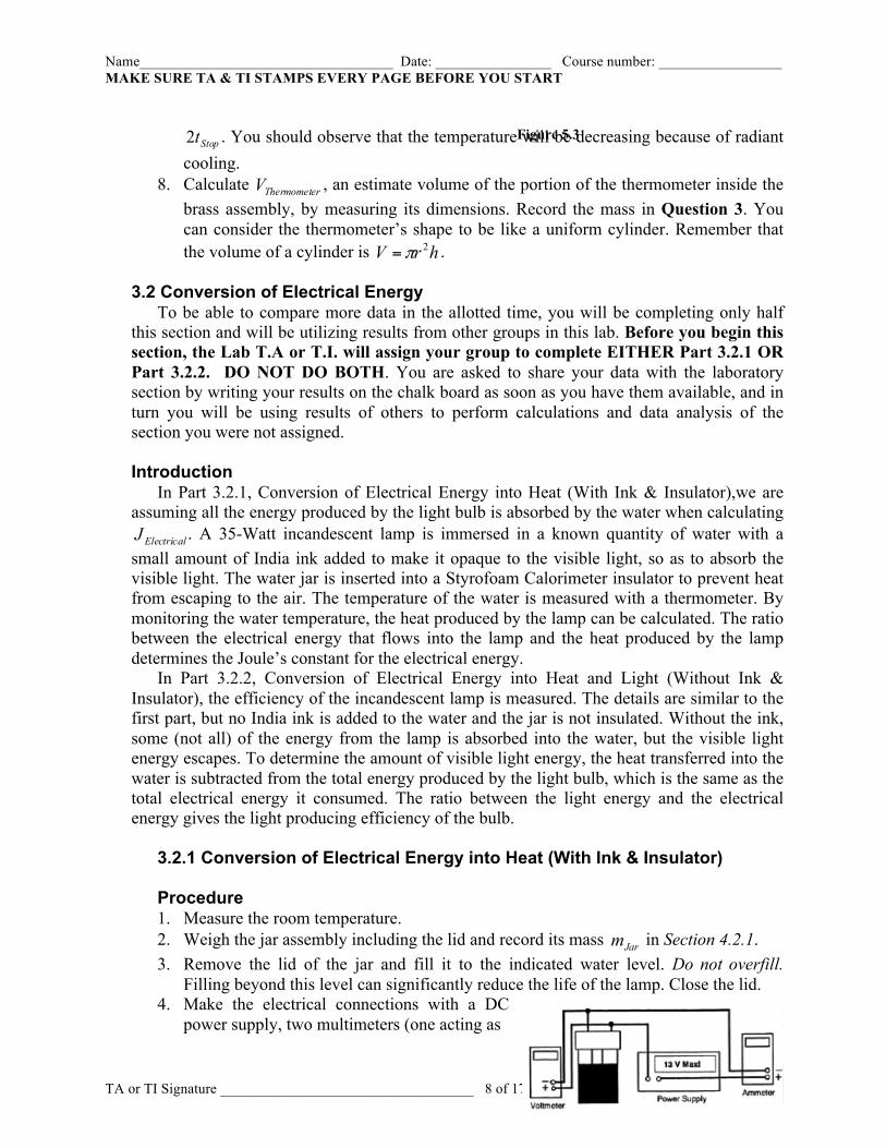
Filling beyond this level can significantly reduce the life of the lamp. Close the lid. 4. Make the electrical connections with a DC
power supply, two multimeters (one acting as
Figure 5.3
Name___________________________________ Date: ________________ Course number: _________________ MAKE SURE TA & TI STAMPS EVERY PAGE BEFORE YOU START
TA or TI Signature ___________________________________ 9 of 17
a voltmeter and the other as an ampmeter) and wires with banana plug connectors. The voltmeter is to measure the voltage difference between the two terminals of the lamp and the ampmeter is to measure the current through the lamp. (See Figure 5.3.)
5. Turn on the power supply and quickly adjust the power supply voltage to about 9.8 volts. At this voltage the ammeter should read about 2.2 amps. Shut the power off right away. Do not leave the power on long, otherwise it will raise the water temperature before the measurement takes place later. Do not let power exceed 35 watts! ( VIP = .)
6. Add enough India ink to the water, so the lamp filament is just barely visible when the lamp is illuminated.
7. Insert the jar into a Styrofoam Calorimeter insulator. 8. Insert a thermometer through the hole in the top of the jar. You may want to swirl the
jar slightly while in contact with table to reach an equilibrium temperature (room temperature). When swirling, hold the rubber part of the insulator in order to reduce the heat going into the jar from your hand.
9. When ready, turn the power supply on and start the timer. 10. On Table 5.2, record the current, voltage, and temperature of water with respect to
time in constant intervals of 60 seconds. Keep an eye on the ammeter and voltmeter throughout the measurement to be sure these values do not change significantly. Continually swirl the jar gently the whole time! As in Step 8, hold the rubber part of the insulator.
11. When the temperature increases by about 8°C, shut off the power but do not stop the timer. Record the time Stopt and temperature.
12. As done in Section 3.1, continue to take temperature readings in 60-seconds intervals until the timer reads Stopt2 . Continue swirling the water gently.
13. Remove the jar from the insulator. Note how much of the thermometer is immersed in the water. Remove the thermometer from the jar. Calculate rThermometeV —an estimate volume of the portion of the thermometer that was immersed in the water. Record it in Section 4.2.1.
14. Weigh the jar assembly including the water WaterJarm + and record it in Section 4.2.1. Discard the water.
3.2.2 Conversion of Electrical Energy into Heat and Light (Without Ink & Insulator)
Procedure 1. Without the India ink and Styrofoam Calorimeter insulator, follow Steps 3 – 14 of
Section 3.2.1. You wish to allow visible light to escape. Since you will not be using the Styrofoam calorimeter insulator hold the lid of the jar when swirling instead. Record your data in Table 5.3.
Name___________________________________ Date: ________________ Course number: _________________ MAKE SURE TA & TI STAMPS EVERY PAGE BEFORE YOU START
TA or TI Signature ___________________________________ 10 of 17
Last Revised on January 8, 2015
EXPERIMENT 5
The Equivalence of Energy: Heat, Mechanical, Electrical, and
Light 4. Post-Laboratory Work [20pts]
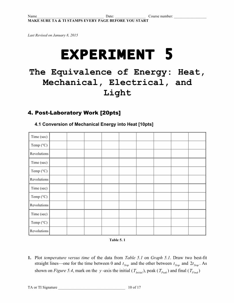
4.1 Conversion of Mechanical Energy into Heat [10pts]
Time (sec)
Temp (°C)
Revolutions
Time (sec)
Temp (°C)
Revolutions
Time (sec)
Temp (°C)
Revolutions
Time (sec)
Temp (°C)
Revolutions
Table 5. 1
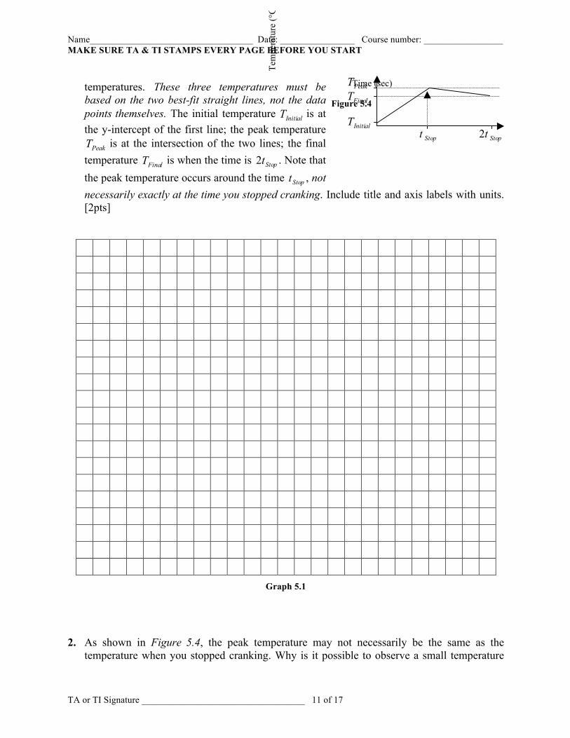
1. Plot temperature versus time of the data from Table 5.1 on Graph 5.1. Draw two best-fit
straight lines—one for the time between 0 and Stopt and the other between Stopt and Stopt2 . As shown on Figure 5.4, mark on the y -axis the initial ( InitialT ), peak ( PeakT ) and final ( FinalT )
Name___________________________________ Date: ________________ Course number: _________________ MAKE SURE TA & TI STAMPS EVERY PAGE BEFORE YOU START
TA or TI Signature ___________________________________ 11 of 17
temperatures. These three temperatures must be based on the two best-fit straight lines, not the data points themselves. The initial temperature InitialT is at the y-intercept of the first line; the peak temperature PeakT is at the intersection of the two lines; the final
temperature FinalT is when the time is Stopt2 . Note that the peak temperature occurs around the time Stopt , not necessarily exactly at the time you stopped cranking. Include title and axis labels with units. [2pts]
Graph 5.1 2. As shown in Figure 5.4, the peak temperature may not necessarily be the same as the
temperature when you stopped cranking. Why is it possible to observe a small temperature
InitialT
FinalTPeakT
Temperature vs. Time
Time (sec)
Tem
pera
ture
(°C
)
Stopt Stopt2
Figure 5.4
Name___________________________________ Date: ________________ Course number: _________________ MAKE SURE TA & TI STAMPS EVERY PAGE BEFORE YOU START
TA or TI Signature ___________________________________ 12 of 17
increase even after you stopped cranking? As a hint, you can imagine holding with you hand one end of a cold metal rod and consider whether the temperature at the other end rises immediately. [2pt]
3. Calculate the quantity D from Equation 5.7, which is the sum of the products of the
involved materials’ masses and specific heats. Include units and show your calculation work (including the calculation for rThermometeV ). [1pt]
Brassm (grams) = 183g
rThermometeV (cm3) = 4. Calculate the work done by the spring on the brass assembly (refer to Equation 5.3). The
apparent temperature change produced by the work is ( ) InitialPeakdUncorrecte TTT −=Δ . Using this uncorrected temperature change and the calculated quantity D from Question 3 and applying them to Equation 5.8, calculate the “uncorrected” Joule constant ( ) dUncorrecteMechanicalJ . Include units and show your calculation work. [1pt]
Total Number of Revolutions N = __________ Radius of Groove Piece r (m) = __________ Average Force Applied by Spring F (N) = __________ ( ) dUncorrecteTΔ (°C) = InitialPeak TT − = __________ 5. While cranking, some heat was lost to the air by radiant/ambient cooling. An estimate of this
heat loss during that time (between 0 and Stopt ) is provided by the temperature drop ( ) FinalPeaklingRadiantCoo TTT −=Δ . The temperature drop should be added to the uncorrected temperature change ( ) dUncorrecteTΔ to compensate for the temperature loss. Thus, the corrected temperature change ( )CorrectedTΔ for Equation 5.8 is ( ) ( ) ( ) lingRadiantCoodUncorrecteCorrected TTT Δ+Δ=Δ . Similar to Question 4, calculate the “corrected” Joule constant ( )CorrectedMechanicalJ . Include units and show your calculation work. [1pt]
Name___________________________________ Date: ________________ Course number: _________________ MAKE SURE TA & TI STAMPS EVERY PAGE BEFORE YOU START
TA or TI Signature ___________________________________ 13 of 17
6. Get an estimate of the error in MechanicalJ by taking 21 of the difference between the
corrected and uncorrected MechanicalJ ’s (( ) ( )
2CorrectedMechanicaldUncorrecteMechanical
MechanicalJJ
J−
=Δ ).
Is your ( )CorrectedMechanicalJ compatible with the accepted value of the Joule’s constant
calJ19.4=J ? You can say it is compatible if the difference between ( )CorrectedMechanicalJ and
the accepted value is at most MechanicalJΔ2 . Include the unit and show your calculation work. [2pt]
7. Discuss one major source of error in this experiment besides the ambient/radiant cooling, and
how it may have affected the measured Joule’s constant. Had that error been removed, would it have increased the measured Joule’s constant or decreased it? Explain. [1pt]
Name___________________________________ Date: ________________ Course number: _________________ MAKE SURE TA & TI STAMPS EVERY PAGE BEFORE YOU START
TA or TI Signature ___________________________________ 14 of 17
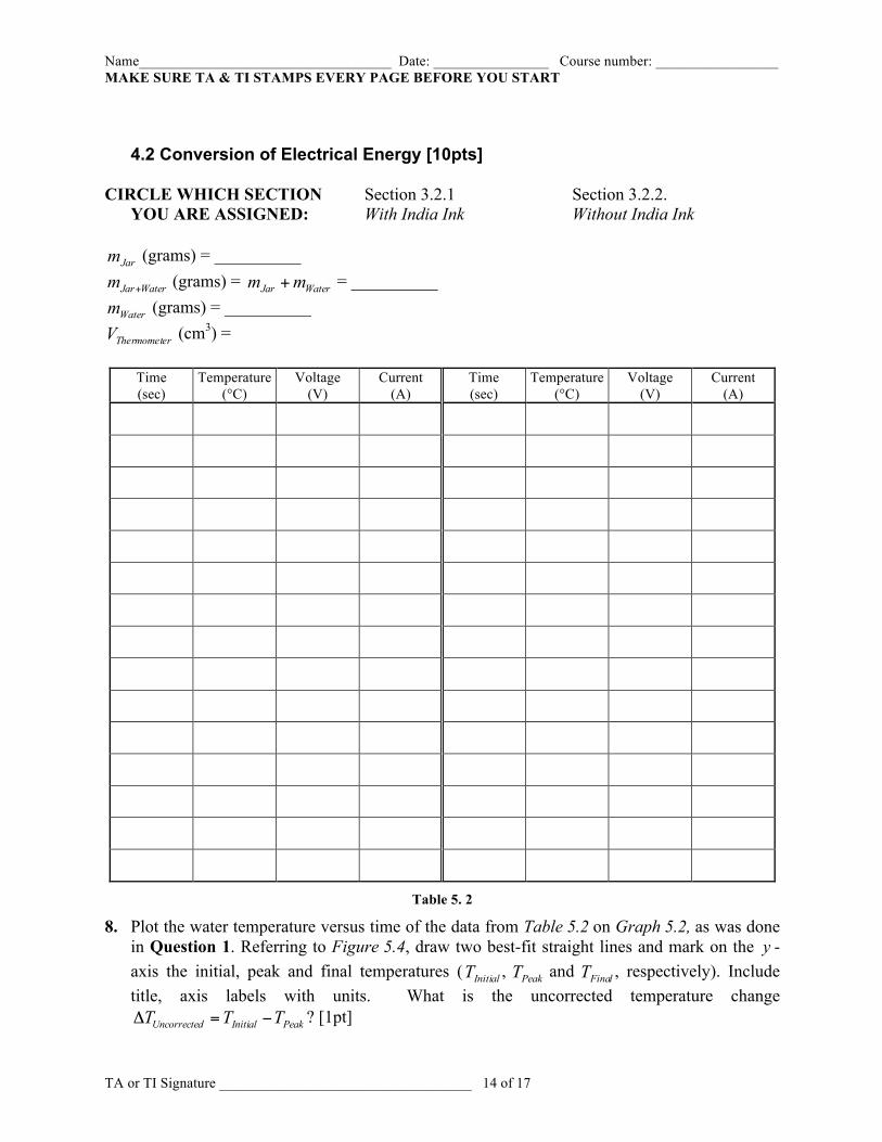
4.2 Conversion of Electrical Energy [10pts]
CIRCLE WHICH SECTION Section 3.2.1 Section 3.2.2. YOU ARE ASSIGNED: With India Ink Without India Ink
Jarm (grams) = __________
WaterJarm + (grams) = WaterJar mm + = __________
Waterm (grams) = __________
rThermometeV (cm3) =
Time (sec)
Temperature (°C)
Voltage (V)
Current (A)
Time (sec)
Temperature (°C)
Voltage (V)
Current (A)
Table 5. 2
8. Plot the water temperature versus time of the data from Table 5.2 on Graph 5.2, as was done in Question 1. Referring to Figure 5.4, draw two best-fit straight lines and mark on the y -axis the initial, peak and final temperatures ( InitialT , PeakT and FinalT , respectively). Include title, axis labels with units. What is the uncorrected temperature change
PeakInitialdUncorrecte TTT −=Δ ? [1pt]
Name___________________________________ Date: ________________ Course number: _________________ MAKE SURE TA & TI STAMPS EVERY PAGE BEFORE YOU START
TA or TI Signature ___________________________________ 15 of 17
Graph 5.2
9. As done as in Question 5, find ( )CorrectedTΔ based on the Question 8’s graph. Record your answer below and in Table 5.3. Include units and show calculation work. [1pt]
10. Calculate the quantity D using Equation 5.11, as done similarly in Question 3. Record your
answer below and in Table 5.3. Include units and show calculation work. [1pt]
Name___________________________________ Date: ________________ Course number: _________________ MAKE SURE TA & TI STAMPS EVERY PAGE BEFORE YOU START
TA or TI Signature ___________________________________ 16 of 17
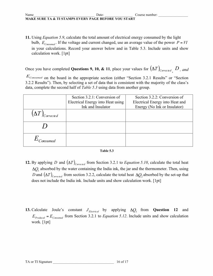
11. Using Equation 5.9, calculate the total amount of electrical energy consumed by the light
bulb, ConsumedE . If the voltage and current changed, use an average value of the power VIP = in your calculations. Record your answer below and in Table 5.3. Include units and show calculation work. [1pt]
Once you have completed Questions 9, 10, & 11, place your values for ( )CorrectedTΔ , D , and
ConsumedE on the board in the appropriate section (either “Section 3.2.1 Results” or “Section 3.2.2 Results”). Then, by selecting a set of data that is consistent with the majority of the class’s data, complete the second half of Table 5.3 using data from another group.
Section 3.2.1: Conversion of
Electrical Energy into Heat using Ink and Insulator
Section 3.2.2: Conversion of Electrical Energy into Heat and
Energy (No Ink or Insulator)
( )CorrectedTΔ
D
ConsumedE
Table 5.3 12. By applying D and ( )CorrectedTΔ from Section 3.2.1 to Equation 5.10, calculate the total heat
1QΔ absorbed by the water containing the India ink, the jar and the thermometer. Then, using D and ( )CorrectedTΔ from section 3.2.2, calculate the total heat 2QΔ absorbed by the set-up that does not include the India ink. Include units and show calculation work. [1pt]
13. Calculate Joule’s constant ElectricalJ by applying 1QΔ from Question 12 and
ConsumedProduced EE = from Section 3.2.1 to Equation 5.12. Include units and show calculation work. [1pt]
Name___________________________________ Date: ________________ Course number: _________________ MAKE SURE TA & TI STAMPS EVERY PAGE BEFORE YOU START
TA or TI Signature ___________________________________ 17 of 17
By what fraction of the accepted Joule’s constant calJ19.4=J does your ElectricalJ differ from
it, i.e. what is J
JJ Electrical − ? What is the corrected MechanicalJ you found in Question 5?
Which one of MechanicalJ and ElectricalJ is closer to the accepted value J ? Explain. [2pt] 14. Find AbsorbedE by the water without the ink, the jar, and the thermometer by expressing the
heat 2QΔ found in Question 12 in units of Joules using Equation 5.14. [1pt] 15. Calculate the efficiency of the lamp in producing light using Equation 5.13. Is the
incandescent lamp more efficient as a light producing source or as a heat source? Explain. [1pt]