Embed Size (px)
Citation preview

Contents lists available at ScienceDirect
Ocean Engineering
journal homepage: www.elsevier.com/locate/oceaneng
Lateral load bearing capacity of offshore high-piled wharf with batter piles
Yaofeng Xiea,⁎, Chenglin Liua, Suyang Gaoa, Jieping Tangb, Yan Chena
a School of Transportation, Southeast University, Chinab College of Geography and Marine Science, Nanjing University, China
A R T I C L E I N F O
Keywords:Finite element modelLateral loadPile top displacementForce-displacement formulaBatter pileHigh-piled wharf
A B S T R A C T
Understanding the lateral load behavior of high-piled wharf is of practical value to structural design, and thehorizontal load bearing capacity of the bent is essential to analyzing the behavior of the high-piled wharf. In thispaper, finite element models of high-piled wharf are built in a general finite element software–ANSYS toinvestigate the lateral loading behavior. Parametric analyses have been performed on the working behavior ofsingle pile with varying slopes and section sizes under different load levels. The behavior of bent with batterpiles under different lateral loads is discussed. The formulas of lateral load vs. horizontal displacement for singlepile and high-piled wharf are formulated and presented in this paper. The numerical simulation results of piletop displacement are found to be in good agreement with those predicted using the theoretical formulapresented in this paper. These formulas, which describe the relationship between top displacement andstiffness, inclination and loads, can be useful to determine the horizontal load bearing capacity of the high-piledwharf with batter piles and can realize the real-time safety monitoring of the high-piled wharf for practicalapplication.
1. Introduction
The high-piled wharf structures have been widely applied in oceanengineering and port engineering, evidenced by the many high-piledwharves constructed in the past three decades. The main loads on thehigh-piled wharf structures are horizontal loads caused by wave load,flow load, wind load and ship impact load (Zhu and Xie, 2015; Xieet al., 2015). While among these loads, the ship load should be the mostemphasized for its largest magnitude, especially for the high-piledwharf located in the open sea.
Considering the fact that the lateral load capacity of plumb pile islimited, high-piled wharves with batter piles have been widely used inoffshore structures in order to achieve improved lateral load capacity.However, with the development of larger size ships and increasingdemand for safety, high-piled wharf is expected to sustain horizontalloads of greater magnitude. The deformation of the wharf structuresubjected to horizontal loads has been a main concern to its safeoperation and thus considered as an important engineering problem byengineers.
Previous studies on high-piled wharf have been mainly based ontheoretical analysis, laboratory tests and the field experiment method.The underlying pile is an important foundation component in the high-piled wharf. The elastic theoretical method proposed by Poulos (1971)is one of the earliest methods for pile foundation analysis, in which the
soil is assumed to be ideally homogeneous and isotropic in elastic halfspace. In the P-Y curve method proposed by Matlock (1970) (where P isthe soil resistance along the pile, Y is the lateral deflection of the pile atthe same location), the pile behavior under the lateral loads isdescribed using a series of nonlinear curves regarded as the functionof the depth along the pile, and also as the representative of the elastic-plastic analysis method. However, these theoretical analysis methodshave limitation in practical application due to the complexity of thesoil-pile interaction. Several researchers also conducted laboratoryexperiments and field tests on the high-piled wharf. Pan et al. (2000)studied the stress and the deformation of the pile under horizontalloading by doing scale model experiments. Bonakdar and Oumeraci(2015) conducted a small scale model tests in a 2 m-wide wave flume toinvestigate the pile group effect on the wave loading of a slender pileand tested different pile arrangement.
With advances in computing technology and finite element analysissoftware, numerical simulation based analysis methods have beenwidely employed, and potentially can be used to investigate the effectof a large number of influencing factors of the pile-supported platformunder horizontal load. Additionally, numerical study is usually lesscostly and less time consuming than physical experiments even withsmall scale model.
Rajashree and Sitharam (2001) conducted finite element analysis ofbatter piles under lateral load by idealizing the piles as beam elements
http://dx.doi.org/10.1016/j.oceaneng.2017.07.001Received 7 November 2016; Received in revised form 5 June 2017; Accepted 1 July 2017
⁎ Corresponding author.E-mail addresses: [email protected], [email protected] (Y. Xie).
Ocean Engineering 142 (2017) 377–387
Available online 13 July 20170029-8018/ © 2017 Elsevier Ltd. All rights reserved.
MARK

and the soil as elastoplastic spring elements. The nonlinear soilbehavior is represented by a hyperbolic relation. The importance ofthe degradation factor and its effect on the P-Y curves on batter pilesare demonstrated.
With the widespread use of pile-supported platform in offshorestructures, research works are also reported on the behavior of offshorehigh-piled wharf under horizontal load. Mostafa and Naggar (2004)studied the response of offshore platform subjected to extreme waveand current loading with varying parameter values. Giannakou et al.(2010) studied the seismic response of batter pile including the“kinematic” pile deformation as well as the “inertial” soil-pile-structureresponse using three-dimensional finite-element model in which elasticbehavior was assumed for the soil, piles and the superstructure. Wangand He (2013) employed a 3-D elastic-plastic finite element model toanalyze the load bearing capacity of vertical pile-supported wharfunder horizontal loads with pseudo-static method. Fan and Yuan(2014) developed finite element models for ship-structure-soil inter-actions and identified four interaction phases for the overall flexuralfailure of the pile-supported platform as initial contact, unloading andfree vibration and loading with approximate velocities.Muthukkumaran and Arun (2015) analyzed the soil-structure interac-tion behavior with varying seabed slope by performing static waveanalysis on a typical fixed offshore platform using finite differencemethod. It is found that the lateral displacement at the pile topincreases as the seabed slope increases.
Although the above literature review shows that a few factors havebeen considered such as the pile length, the stiffness of pile, the loadinclination angle and the pile spacing of pile group, few researches onthe displacement calculation method of the high-piled wharf underhorizontal loads have been done. Therefore, it is of interest to carry outthe research on the displacement calculation method for the high-piledwharf under horizontal loads. Theoretical research by Xie (1996)suggested that the problem of analyzing high-piled wharf can beresolved into analyzing bent structure. Determining the workingproperties of bent structure is the key component in studying thebehavior of high-piled wharf.
In the present study, the finite element analysis software package-ANSYS is employed to simulate the deformation of high-piled wharfunder the lateral load. The relationship between the lateral load anddeformation is expatiated, and the theoretical formula is proposed. Thefield berthing test is used to investigate the theoretical formula. In thisway, the lateral displacement under certain lateral load and the lateralbearing capacity under a limited displacement can be predicted.
2. Numerical model of high-piled wharf: description
2.1. Prototype of bent
As shown in Fig. 1, the section of the beam is an inverted “T” shape.The width of the lower rectangular beam section is 1.20 m, and itsdepth is 1.10 m. The width of the upper rectangular beam sectionmeasures 0.70 m, and its height measures 2.12 m. The base of the pilesis assumed to be located at the same elevation. The section size of allthe piles is equal to 0.6 m×0.6 m. The free length (i.e., length of theunburied part) of the piles in the vertical direction is 10 m. From left toright, the piles are labeled as #1 to #5 or from #1 to #9 respectively.The horizontal load is assumed to be a static concentrated load and isapplied to the centroidal axis of the beam at one time for each loadingcase. The load direction is pointing to right. The parameters of the soiland the piles are shown in Tables 1, 2. Three different designs of thebent prototype models are showed in Fig. 2(a) to 2(c) respectively.
2.2. Basic assumption in the model
The following basic assumptions are made in the finite elementmodel of the prototype high-piled wharf structures.
(1) In the model, the soil is assumed to be continuous, homogeneous,and isotropic. The boundary conditions of the soil are given: thebottom surface of soil is constrained in all directions, and the sidesurfaces of soil are constrained in the horizontal directions.
(2) The elastic modulus and Poisson's ratio of the surrounding soilremain constant with the pile embedded in it.
(3) The pile and the soil are both assumed to behave as elastic-plasticmaterial. The soil follows the Drucker-Prager Yield Criteria, whichwas also employed in previous study by Wang et al. (2014) as aclassical model.
(4) Pile-soil interface is represented with a contact surface, andbottom section of the pile is laid on a horizontal surface.
2.3. Engineering parameters
The parameters of the soil and piles are listed in Tables 1 and 2,respectively. The parameters used for plastic soil behavior is materialconstant β and yield strength σy . β = sin
sin2 ∅
3 (3 − ∅), σ =y
ccossin
6 ∅3 (3 − ∅)
(ANSYS
Help version 16.0, 2014). Where ∅ refers to the internal friction angle,and c refers to the cohesion, the parameters ∅ and c are presented inTable 1.
The compressive strength of the concrete is C40. These engineeringparameter values are taken from a real offshore pile-supportedstructure located in the Yangtze River estuary, China.
2.4. Contact surface setting
In the ANSYS model, the contact surface element is adopted tosimulate the pile-soil interaction. In general, the following rules andsome research experience are followed to define the target surface andcontact surface between the piles and the soil,
(1) The fine mesh surface should be set as the contact surface, and therough mesh surface should be set as the target surface.
(2) The flat and concave surface should be set as the target surface.(3) The harder one should be set as the target surface, and the softer
one should be set as the contact surface.(4) The surface with higher order element as base elements should be
set as the contact surface, and the surface with lower order elementshould be set as the target surface.
Fig. 1. The section of the beams.
Y. Xie et al. Ocean Engineering 142 (2017) 377–387
378

(5) The larger surface should be set as target surface, and the smallersurface should be set as contact surface.
(6) The nodes belonging to both contact surfaces are not required to becorresponding to each other, but more accurate results can beobtained if they are corresponding to each other.
(7) The continuity of the main surface should be ensured.(8) The normal directions of a pair of surfaces should be opposite to
each other.(9) The surface with larger stiffness should be the main surface.
In the ANSYS software package, Conta 174 is an 8-node elementthat is generally used for rigid-flexible and flexible-flexible contactanalysis and is applicable for 3-D geometries. Targe 170 is intended torepresent 3-D target surfaces for the associated contact elements (e.g.Conta 174). To create the “contact-target pair”, the pile is selected asthe target surface and the target segment element Targe 170 is used tooverlay the pile body. Correspondingly, the soil is set as the subordinatecontact surface and the surface-to-surface contact element Conta 174 isused to overlay the soil surface which is associated with the pile body inthe present finite element analysis (ANSYS Help version 16.0, 2014).
The node pairs of the discrete element built on the contact surfacesshould satisfy the displacement compatibility condition and theHooke's Law. The soil and the piles cannot penetrate into each other.The pressure is the only normal force, and the friction force is the onlytangential force between the soil and piles. The friction coefficient istaken as 0.2.
3. Finite element modeling of single pile
3.1. Model details
Finite element models of a single pile with different slopes andsubjected to different loads were built in ANSYS. The slopes of thebatter piles are chosen as 1:7, 1:6, 1:5, 1:4 and 1:3 respectively. Thehorizontal load is applied to the top end of the pile. The bases of thepiles are all located at the same elevation level. The free length of thepiles in the vertical direction is 10 m. The elastic modulus andPoisson's ratio are given in Table 2. By comparing the results frommodel simulation results, the relationships between the displacementand slope, load and stiffness can be established for the piles.
3.2. Finite element model analyses
The bottom and surroundings of the soil body are set as fixedconstraints. The displacements of the plumb pile and the batter pile areobtained when applying different loads to the piles separately.
In this part, in order to understand the relationship between thedisplacements of piles and different slopes and stiffness, the pilesections are set to be 0.4 m×0.4 m, 0.6 m×0.6 m, 0.8 m×0.8 m,1.0 m×1.0 m, respectively; other pile parameters besides the pile
sections are the same as those listed in Table 2. The displacements ofthe piles with different slopes and stiffness subjected to different loadsrecorded from finite element analysis results are listed in Tables 3–5.
3.3. Behavior analysis of single pile
3.3.1. Relationship between top displacement and slope of single pileIt is found that the relationship between the horizontal displace-
ment of the pile top and the pile inclination to the power of m is almostlinear, as shown in Fig. 3. The least square method is adopted to fit thecomputed data.
Eq. (1) can be expressed as below,
y α y= (1 + )sm
0 (1)
where ys is the horizontal displacement of single pile top (unit = m), α isthe inclination angle between pile longitudinal axis and verticaldirection (unit = radian), y0 is the horizontal displacement of theplumb pile top under identical load (unit = m), and m is the exponentthat is related to the inclination angle (Generally, it varies from 1.3 to1.5.).
3.3.2. Top displacements of single plumb pileThe plumb pile inserted in the soil is similar to a cantilever beam
structure. Therefore, it is reasonable to assume that the top horizontaldisplacement of the plumb pile is inversely proportional to its stiffnesswhile the top displacement is proportional to its free length cubed. Eq.(2) below can be written out for the top force-displacement of theplumb pile,
y l l Ft EI= ( + ) /(3 )q0 03 (2)
where Ft is the horizontal load acting on the pile top (unit: kN ), l0 is thefree length of the pile in vertical direction (unit: m), lq is the distancebetween the embedded point (all piles are assumed to be embedded attheir maximummoment points) and the soil surface (unit: m), and EI isthe flexural stiffness of the pile (unit: kN m· 2).
l Ft b= (6 + 0.016 )q (3)
Where b is the width of the square-section pile (unit: m).Fig. 4 shows the relationship between the flexibility (inverse of the
stiffness) and the top horizontal displacement of the plumb pile. Thecurves are seen to match very well with those predicted by Eq. (2).
In Eq. (2), y0 is expressed as a function of the flexural stiffness of thepile, the property of the soil and the load. The embedded depth isgreater when the load is larger. Further research may be needed if otherfactors are to be taken into account in this formula.
By combing the above equations, the top force vs. displacementrelationship of single pile can be derived as Eq. (4) below,
y α l l Ft EI= (1 + )( + ) /(3 )sm
q03 (4)
Fig. 5 shows the results of the theoretical calculation and numerical
Table 1The parameters of soil.
Material Density (kg m/ 3) Elastic modulus (Mpa) Poisson's ratio Cohesion (kPa) Internal friction angle (°) Expansion angle (°)
Soil 1950 8.6 0.3 9 33 30
Table 2The parameters of piles.
Material Section Size (m) Elastic modulus (Mpa) Yield Stress (Mpa) Moment of Inertia (m4) Poisson's ratio Length (m) Buried depth (m)
Plumb pile 0.6×0.6 3.25×10⁴ 65 0.0108 0.2 38 28Batter pile(1:5) 0.6×0.6 3.25×10⁴ 65 0.0108 0.2 38.8 28.6
Y. Xie et al. Ocean Engineering 142 (2017) 377–387
379

simulation. In Fig. 5(a), the size of the pile is m m0.6 × 0.6 . In Fig. 5(b),the size of the pile is m m0.8 × 0.8 . In Fig. 5(c), the size of the pile is
m m1.0 × 1.0 . As can be seen from Fig. 3, the results of the theoreticalcalculation match well with the data from the numerical model study.Fig. 6 shows the lateral load-displacement relation for single pile withvarious pile slope, and the pile section is m m0.6 × 0.6 .
4. Finite element analysis of pile-supported bent with batterpiles
4.1. FE model and FEA results of bent with plumb piles
4.1.1. Model description of bent with plumb pilesThere are 5 piles total in the bent model, and these 5 piles are all
plumb piles. In the bent, the spacing between the piles is 2 m, 4.25 m,
Fig. 2. Bent structure layout and dimensions. (a). Layout of bent structure with all plumb piles. (b). Layout of bent structure with one pair of batter piles. (c). Layout of bent structurewith two pairs of batter piles.
Table 3Horizontal displacements of single pile with different stiffness under 5 kN load.
Stiffness
EI (kN·m2)
Pilesection(m m× )
Horizontal displacement of pile top (m)
Plumb pile Batterpile(1:7)
Batterpile(1:6)
Batterpile(1:5)
Batterpile(1:4)
Batterpile(1:3)
69,333.33 0.4×0.4 4.68 E−02 4.87E−02
4.92E−02
5.05E−02
5.27E−02
5.68E−02
351,000 0.6×0.6 1.20E−02 1.25E−02
1.27E−02
1.29E−02
1.34E−02
1.45E−02
1,109,333 0.8×0.8 4.88E−03 5.12E−03
5.17E−03
5.28E−03
5.45E−03
5.85E−03
2,708,333 1.0×1.0 2.52E−03 2.64E−03
2.67E−03
2.73E−03
2.83E−03
3.02E−03
Table 4Horizontal displacements of single pile with different stiffness under 10 kN load.
Stiffness
EI (kN·m2)
Pilesection(m m× )
Horizontal displacement of pile top (m)
Plumb pile Batterpile(1:7)
Batterpile(1:6)
Batterpile(1:5)
Batterpile(1:4)
Batterpile(1:3)
69,333.33 0.4×0.4 9.54 9.97 1.01 1.03 1.08 1.17E−02 E−02 E−01 E−01 E−01 E−01
351,000 0.6×0.6 2.42 2.54 2.56 2.62 2.72 2.95E−02 E−02 E−02 E−02 E−02 E−02
1,109,333 0.8×0.8 9.77 1.02 1.03 1.06 1.09 1.17E−03 E−02 E−02 E−02 E−02 E−02
2,708,333 1.0×1.0 5.05 5.28 5.35 5.46 5.65 6.03E−03 E−03 E−03 E−03 E−03 E−03
Table 5Horizontal displacements of single pile with different stiffness under 50 kN load.
Stiffness
EI (kN·m2)
Pilesection(m m× )
Horizontal displacement of pile top (m)
Plumb pile Batterpile(1:7)
Batterpile(1:6)
Batterpile(1:5)
Batterpile(1:4)
Batterpile(1:3)
351,000 0.6×0.6 1.33 1.41 1.43 1.47 1.53 1.68E−01 E−01 E−01 E−01 E−01 E−01
1,109,333 0.8×0.8 5.11 5.40 5.49 5.59 5.82 6.29E−02 E−02 E−02 E−02 E−02 E−02
2,708,333 1.0×1.0 2.59 2.72 2.76 2.83 2.93 3.15E−02 E−02 E−02 E−02 E−02 E−02
Fig. 3. Displacement of pile top vs. pile inclination angle. (The exponent m here is equalto 1.4).
Y. Xie et al. Ocean Engineering 142 (2017) 377–387
380
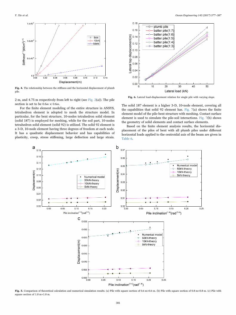
2 m, and 4.75 m respectively from left to right (see Fig. 2(a)). The pilesection is set to be m m0.6 × 0.6 .
For the finite element modeling of the entire structure in ANSYS,tetrahedron element is adopted to mesh the structure model. Inparticular, for the bent structure, 10-nodes tetrahedron solid element(solid 187) is employed for meshing, while for the soil part, 10-nodestetrahedron solid element (solid 92) is utilized. The solid 92 element isa 3-D, 10-node element having three degrees of freedom at each node.It has a quadratic displacement behavior and has capabilities ofplasticity, creep, stress stiffening, large deflection and large strain.
The solid 187 element is a higher 3-D, 10-node element, covering allthe capabilities that solid 92 element has. Fig. 7(a) shows the finiteelement model of the pile-bent structure with meshing. Contact surfaceelement is used to simulate the pile-soil interactions. Fig. 7(b) showsthe geometry of solid elements and contact surface elements.
Based on the finite element analysis results, the horizontal dis-placement of the piles of bent with all plumb piles under differenthorizontal loads applied to the centroidal axis of the beam are given inTable 6.
Fig. 4. The relationship between the stiffness and the horizontal displacement of plumbpile.
Fig. 5. Comparison of theoretical calculation and numerical simulation results. (a) Pile with square section of 0.6 m×0.6 m. (b) Pile with square section of 0.8 m×0.8 m. (c) Pile withsquare section of 1.0 m×1.0 m.
Fig. 6. Lateral load-displacement relation for single pile with varying slope.
Y. Xie et al. Ocean Engineering 142 (2017) 377–387
381

4.1.2. Displacement of bent with plumb pilesFig. 8(a) and Fig. 8(b) show the displacement profiles along the
length of pile #1 and pile #3 in the bent with all plumb piles underdifferent horizontal loads respectively. Fig. 9 presents the lateral load-displacement relation of bent with plumb piles.
It is shown in this study that under the same load, pile-topdisplacements of each pile are basically the same and under differentloads, the displacements of each pile all decrease to zero at the section15-m down from the pile top.
4.2. FE model and FEA results of bent with a pair of batter piles
4.2.1. Model description of bent with a pair of batter pilesThe finite element model of the bent includes five piles including a
pair of batter piles with a slope of 1:5. In the bent with batter piles, thespacing between each pile are 2 m , 4.25 m , 2 m, and 4.75 m at top(see Fig. 2(b)). The pile section is set to be m m0.6 × 0.6 .
In the finite element model of the bent, the structure element, thecontact surface element and other related settings are identical to thosein the finite element model of the bent with all plumb piles. Fig. 10shows the element division of the bent model.
4.2.2. Displacement of bent with a pair of batter pilesThe lateral load is applied to the centroidal axis of the beam. From
the finite element simulation results, it is seen that the top displace-ments of all piles in the bent are the same in the horizontal direction atall load levels. Table 7 lists the top displacements of the bent.
This study shows that: (1) At the same load level, pile-topdisplacements of all piles are basically the same; (2) Under differentload levels, the displacements of the three plumb piles all decrease tozero at locations 15-m away from the pile top; (3) The displacement ofbatter pile #3 changes from positive to negative values more quicklythan those of plumb piles; (4) The displacement of batter pile #4 doesnot switch direction along its length.
Fig. 11(a) and Fig. 11(b) show the distribution profile of thedisplacement responses along pile #1 and pile #3 of the bent with a
pair of batter piles in vertical direction under different horizontal loadlevels respectively. Fig. 12 illustrates the lateral load-displacementrelation of bent with a pair of batter piles.
4.3. FE model and FEA results of bent with two pairs of batter piles
4.3.1. Model description of bent with two pairs of batter pilesThe finite element model of the bent is composed of nine piles
including two pairs of batter piles with a slope of 1:5. In the bent, thespacing between each pile are 2 m, 4.25 m, 1.6 m, 2.65 m, 8.75 m,2.65 m, 2.1 m, and 2 m from left to right pile top respectively(Fig. 2(c)). The pile section is set to be m m0.6 × 0.6 .
In the finite element model of the bent, the structure element, thecontact surface element and other related settings are identical to thosein the finite element model of the bent with all plumb piles. Fig. 13shows the element division of the bent model.
4.3.2. Displacement of bent with two pairs of batter pilesThe lateral load is applied to the centroidal axis of the beam. The
pile top displacement of bent with two pairs of batter piles arepresented in Table 8.
This study shows that: (1) At the same load level, pile-topdisplacements of all piles are basically the same; (2) Under differentload levels, the displacements of the four plumb piles all decrease tozero at locations 15-m away from the pile top; (3) Because batter pile#4 and batter pile #6 are under tension, the displacements of the lowerhalf of these two piles keep as negative, and the smaller the load is, thecloser the zero displacement point is to pile top; (4) Because pile #5and pile #7 are under compression, the displacements of these twopiles remain in the positive direction along its length.
Fig. 14(a) to 14(c) show the distribution profile of the displacementresponses along pile #1, pile #4 and pile #6 of the bent with two pairsof batter piles under different horizontal load levels respectively.Fig. 15 presents the lateral load-displacement relation for bent withtwo pairs of batter piles.
Fig. 7. (a) Element division of bent with all plumb piles. (b) Geometry of solid elements and contact surface elements.
Table 6Horizontal displacement of the piles of bent with all plumb piles.
Load (kN ) Displacement of pile at soil surface (m) Pile top displacement (m)
Pile #1 Pile #2 Pile #3 Pile #4 Pile #5
100 3.91E−03 3.95E−03 4.02E−03 3.92E−03 3.62E−03 2.55E−02200 7.95E−03 7.93E−03 8.13E−03 7.87E−03 7.31E−03 4.75E−02400 1.76E−02 1.72E−02 1.77E−02 1.71E−02 1.59E−02 9.64E−02600 2.96E−02 2.84E−02 2.94E−02 2.80E−02 2.60E−02 1.49E−01800 4.37E−02 4.17E−02 4.31E−02 4.08E−02 3.76E−02 2.07E−01
Y. Xie et al. Ocean Engineering 142 (2017) 377–387
382

4.4. Pile group coefficients of high-piled wharf
Based on the result of numerical simulation and analytical study,the displacement at the top section of each pile are found to be almostthe same. Considering that the minimum pile space is larger than 3times of pile section, which has little influence on the pile interaction.The pile group coefficient is regarded to be merely related to thenumber of piles from the view of engineering practice. The pile groupcoefficients formula can be expressed as follows:
For vertical high-piled wharf:
η n=1 10.99 (5)
For high-piled wharf with batter piles:
η n n=1 10.99
20.22 (6)
And the pile group coefficients of the soil surface can be expressedas:
η = 1.0~1.22 (7)
where η1 is the pile group coefficients of pile top; η2 is the pile groupcoefficients of soil surface; n1 and n2 are total numbers of plumb pilesand batter piles respectively.
5. Load vs. displacement relationship of high-piled wharfwith batter piles
Based on the data from the afore-mentioned finite element simula-tion study, the relationship of lateral load and bent displacement can beestablished and presented in this section. The bent top displacement iscomprised of two parts: pile displacement at the soil surface section,wh,and the deformation of the pile portion above the soil surface,wd .Combined with theoretical analysis presented below, pile-top displace-ment formula can be derived. The following assumptions are made inthe formulation presented here: (1) pile top's horizontal displacementsare uniform along the wharf platform beam; (2) horizontal force istransmitted along the beam, and then to the piles.
Free body diagram of the beam and piles above the soil surface isschematically shown in Fig. 16. Fig. 16 illustrates the process of solvingthe high-piled wharf with batter piles using displacement method instructural mechanics. Generally, F is lateral load acting on the beam, F′i
Fig. 8. Displacement profiles of Piles #1 and #3 subjected to lateral load. (a) Pile #1 of bent with all plumb piles. (b) Pile #3 of bent with all plumb piles.
Fig. 9. Lateral load-displacement relation of bent with all plumb piles.
Fig. 10. Meshed finite element model of the bent structure with a pair of batter piles.
Table 7Pile top horizontal displacement of the bent with a pair of batter piles.
Load (kN ) 100 200 400 600 800 1000
Displacement (m) 2.06E−02 4.57E−02 8.95E−02 1.38E−01 1.90E−01 2.46E−01
Y. Xie et al. Ocean Engineering 142 (2017) 377–387
383

is the shear force acted on the pile head while the Fi is the shear forceacting on the beam, whose value is equal to F′i . The lower end sectionsof all piles are assumed to be embedded at their maximum momentpoints, and rigid connection assumption is adopted for the connectionof the upper pile end section and beam (for the sake of showing internal
forces, the piles are drawn separately from the beam at the section cut).From basic structural mechanics theory, the pile top displacementformula can be derived as below,
w w F l EIcos α cos α F l EAcosα sin α= = ( /12 ) +( / )d i i i i i i i3 3 2 2 (8)
where i denotes the ith pile. αi is the inclination angle between ith pilelongitudinal axis and vertical direction, as shown in Fig. 16. Accordingto the Newton's third law, the total force acting on the beam F is equalto the forces contributed by all connecting piles,
∑ ∑F F w= =+i
i n
ii
i ni
lEIcosα
lsin αEAcosα=1
=
=1
=
12 iii
3 2
(9)
Because the pile top displacements are the same, and if the slope ofall batter piles is assumed to be constant, the following formula can bewritten out for the displacement of pile above soil surface,
wη F
EIcosα=
+d
nl
nl l I A sin α
1
12 12+12 ( / )
13
23 2
⎡⎣⎢
⎤⎦⎥ (10)
According to the data of plumb pile at soil surface from the FEsimulation study, the pile's horizontal displacement at soil surfacesection can be expressed as,
wη
n n
FlkEI
=+ +
5h
cosαIsin α
Al cosα
2
1 21 12
2
2
2
⎛⎝⎜
⎞⎠⎟ (11)
Combining Eq. (10) with Eq. (11), the total pile top displacementcan be written as,
w w wη F
EIcosα
η
n n
FlkEI
= + =+
++ +
5
d hn
ln
l l I A sin α cosαIsin α
Al cosα
1
12 12+12 ( / )
2
1 21 12
2
13
23 2
2
2
⎡⎣⎢
⎤⎦⎥
⎛⎝⎜
⎞⎠⎟
(12)
where w is the pile top displacement, wd is the pile top displacementdue to the deformation of the segment above the soil surface, wh is thepile top displacement at soil surface, η1,η2,n1 and n2 can be referred to
Fig. 11. The distribution law of displacements along piles in vertical direction. (a) Pile #1 of bent with a pair of batter piles. (b) Pile #3 of bent with a pair of batter piles.
Fig. 12. Lateral load-displacement relation of bent with a pair of batter piles.
Fig. 13. Meshed finite element model of the bent structure with two pairs of batter piles.
Table 8Pile top horizontal displacement of the bent with two pairs of batter piles.
Load (kN ) 200 400 600 800 100 1400 1600 2000
Displacement (m) 1.64 3.47 5.40 7.44 9.6 1.43 1.68 2.24E−02 E−02 E−02 E−02 E−02 E−02 E−01 E−01
Y. Xie et al. Ocean Engineering 142 (2017) 377–387
384

Eqs. (5) to (7), α is the slope of batter pile, E is the modulus of elasticityof pile material, I is the moment of inertia of the pile's section, k is the
pile deformation coefficient(k = m bEI1 1 ,m1 is the horizontal resistance
coefficient of foundation soils), b1 is the pile calculation widthb K K ·K·b( = · )f1 0 , b is the pile section width, Kf is the property conver-sion coefficient (K = 1.0f ), K0 is the force conversion coefficient(K b= 1 + 1/0 ), and K is the pile influence coefficient(K = 1.0). l isdistance from the pile top section to maximum moment point along
pile body in vertical direction (l l l= + q0 ), l0 is the distance from the piletop to soil surface in vertical direction, lq is the distance between theembedded point.
Based on the above formulation, Eq. (12) can be used to determinethe pile top force-displacement relationship. Table 9 shows the resultsof both numerical simulation study and the results predicted using Eq.(12).
In order to verify the finite element model and theoretical formula,a berthing test for high-pile wharf was conducted. The experimentaltest site is located in the middle and lower reaches of the Yangtze River.The high-pile wharf measures 700 m×300 m, comprising of elevensegmentations. The berthing test was focused on the seventh segmen-
Fig. 14. Distribution profile of horizontal displacements along piles. (a) Pile #1 of bent with two pairs of batter piles. (b) Pile #4 of bent with two pairs of batter piles. (c)Pile #6 of bentwith two pairs of batter piles.
Fig. 15. Lateral load-displacement relation for bent with two pairs of batter piles.
Fig. 16. Free body diagram of bent model.
Y. Xie et al. Ocean Engineering 142 (2017) 377–387
385

tation. The bent is composed of nine piles including two pairs of batterpiles with a slope of 1:5. In the bent, the spacing between each pile are2 m, 4.25 m, 1.6 m, 2.65 m, 8.75 m, 2.65 m, 2.1 m, and 2 m from left toright pile top, respectively. The pile section is 0.6 m×0.6 m, as shown inFig. 2(c).
The field test data was collected from the ‘Youmei’ Ship (the shipgross tonnage is 36,498 t) berthing test, in which force of the rubberfender and displacement of the bent were measured in separateberthing test (JPWTRCET, 2012). In berthing test, the ship grosstonnage is calculated by measuring waterline depth, and the speed andangle of ship berthing were obtained from GPS data. The locations ofthe inclinometers along the pile body are shown in Fig. 17.
Fig. 18 shows the comparison of results from numerical simulationstudy, theoretical formula (Eq. (12)) and experimental data (berthing
test). As is shown in Fig. 18, the results from the numerical simulationstudy and those predicted by the theoretical formula are close to thethree berthing test data points. It should be noted that the berthing testonly involved load amplitude lower than 450 kN. If the force furtherincreases, the results given by the theoretical formula are slightlyhigher than the numerical simulation results. This clearly shows thatEq. (12) can be used to estimate the bearing capacity of the bent.
The bent structure is the basic structure of a high-piled wharf.Previous research has shown that the calculation formulas for high-piled wharf can be extended to those for the bent structure in oceanengineering and port engineering. Eq. (12) is capable of estimating thebearing capacity of the high-piled wharf with batter piles.
6. Conclusions
To study the working behavior of offshore high-piled wharf underlateral loading, finite element models of single pile and high-piledwharf are built in a general finite element analysis software – ANSYS.Parameters including the slopes, section sizes of the piles, and lateralload magnitude were taken into account for single pile analysis. Theslopes of the batter piles were 1:7, 1:6, 1:5, 1:4, and 1:3, respectively.Pile-soil interface is modeled with the contact surface element inANSYS. The behavior of bent structure with batter piles under differentlateral loads is discussed. Based on the analysis results from the modelsconsidered in this study, the following conclusions can be drawn.
(1) The top displacement of the plumb pile is almost linearly propor-tional to the horizontal load under allowable working conditions.
(2) The single pile force vs. displacement formula and high-piledwharf force vs. displacement formula are presented based on theresults in the present study. Through comparing the results fromthe simulation results and berthing test results with theoretical
Table 9Comparison of pile top displacement from numerical simulation and Eq. (12).
Load (kN ) Top displacement from FE simulation (m) Top displacement From Eq. (12) (m)
Plumb pile bent One batter pile bent Two batter piles bent Plumb pile bent One batter pile bent Two batter piles bent
200 4.75E−02 4.57E−02 1.64E−02 3.99E−02 3.60E−02 1.75E−02400 9.64E−02 8.95E−02 3.47E−02 7.98E−02 7.20E−02 3.49E−02600 1.49E−01 1.38E−01 5.40E−02 1.20E−01 1.08E−01 5.24E−02800 2.07E−01 1.90E−01 7.44E−02 1.60E−01 1.44E−01 6.99E−021000 2.46E−01 9.60E−02 1.80E−01 8.74E−02
Fig. 17. Arrangement of inclinometers along the pile body (unit: mm).
Fig. 18. Comparison of numerical simulation, theoretical formula and experimental(berthing test) results.
Y. Xie et al. Ocean Engineering 142 (2017) 377–387
386

formula, Eq. (12) is shown to be reasonably accurate when the loadamplitude is lower than 450 kN. This formula is of practical valueto offshore platform structure designs.
(3) Considering that the allowable lateral displacement of high piledwharf is limited in a certain range, as well as the lateral force. Thelateral load acting on the high-piled wharf can be obtained throughthe Eq. (12) if the lateral displacement of the high-piled wharf isprovided. Or to get the lateral displacement according to the lateralload through Eq. (12). For practical application, according to theforce vs. displacement relationship, the real-time monitoring canbe realized.
(4) It should also be noted that the Eq.(12) is specific for the soilmechanical properties and pile parameters analyzed in this paperand should be cautious when applied to other situations.
The analysis of high-piled wharf can be extended to the bentstructure in ocean engineering and port engineering, and the forcevs. displacement relationship of the bent structure is thus a keyresearch topic.
References
Ansys Help, 2014. version16.0. Ansys Inc.,Bonakdar, L., Oumeraci, H., 2015. Pile group effect on the wave loading of a slender pile:
a small-scale model study. Ocean Eng. 108, 449–461.Fan, W., Yuan, W.C., 2014. Numerical simulation and analytical modeling of pile-
supported structures subjected to ship collisions including soil-structure interaction.
Ocean Eng. 91, 11–27.Giannakou, A., Gerolymos, N., Gazetas, G., et al., 2010. Seismic behavior of batter piles:
elastic response. J. Geotech. Geoenviron. Eng. 136 (9), 1187–1199.Jiangsu provincial water transport research center of engineering technology
(JPWTRCET), 2012. The report on deformation characteristics of high-pile pierstructure under berthing load.
Matlock, H., 1970. Correlations for design of laterally loaded piles in soft clays. In:Proceedings of the 2nd Annual Offshore Technology Conference. OTC, Vol.1, pp.577–594.
Mostafa, Y.E., Naggar, M.H.E., 2004. Response of fixed offshore platforms to wave andcurrent loading including soil–structure interaction. Soil Dyn. Earthq. Eng. 24,357–368.
Muthukkumaran, K., Arun, K.S., 2015. Erratum to: Effect of seabed slope on the pilebehaviour of a fixed offshore platform under lateral forces. J. Ocean Eng. Mar.Energy 1 (3), 223–236.
Pan, J., Goh, A., Wong, K., Teh, C., 2000. Model tests on single piles in soft clay. Can.Geotech. J. 37 (4), 890–897.
Poulos, H.G., 1971. Behavior of laterally loaded piles: I-single piles. J. Soil Mech. Found.Div. 97 (5), 711–731.
Rajashree, S., Sitharam, T., 2001. Nonlinear finite-element modeling of batter pilesunder lateral load. J. Geotech. Geoenviron. Eng. 127 (7), 604–612.
Wang, Y.Z., He, L.L., 2013. Finite element analysis on bearing capacity of all-vertical-piled wharf in offshore deep-water. Ocean Eng. (Haiyang Gongcheng) 31 (6),45–52, (in Chinese).
Wang, Y.Z., He, L.L., Wang, Z.Y., 2014. Research on dynamic simplified calculationmethod of all-vertical-piled wharf in offshore deep-water. Rock. Soil Mech. 35 (10),2969–2976, (in Chinese).
Xie, Y.F., 1996. Behavior and bearing capacity of laterally loaded pile groups. Chin. J.Geotech. Eng. 18 (6), 39–45, ( in Chinese).
Xie, Y.F., Liu, X.X., Tang, J.P., et al., 2015. Research on berthing capability and workingproperty of pontoon bases. J. Coast. Res. 73, 505–510.
Zhu, D.T., Xie, Y.F., 2015. Hydrodynamic characteristics of offshore and pilebreakwaters. Ocean Eng. 104, 257–265.
Y. Xie et al. Ocean Engineering 142 (2017) 377–387
387