Embed Size (px)
Citation preview

Lateral Load Testing of the Advanced Stirling Convertor(ASC–E2) Heater Head
Peggy A. Cornell 1 and David L. Krause2
NASA Glenn Research Center, Cleveland, Ohio, 44135
Glen Davis3
Sunpower, Inc., Athens, Ohio, 45701
Malcolm G. Robbie4 and David A. Gubics5
QinetiQ North America, Cleveland, Ohio, 44135
Free-piston Stirling convertors are fundamental to the development of NASA’s nextgeneration of radioisotope power system, the Advanced Stirling Radioisotope Generator(ASRG). The ASRG will use General Purpose Heat Source (GPHS) modules as the energysource and Advanced Stirling Convertors (ASCs) to convert heat into electrical energy, andis being developed by Lockheed Martin under contract to the Department of Energy.Achieving flight status mandates that the ASCs satisfy design as well as flight requirementsto ensure reliable operation during launch. To meet these launch requirements, GRCperformed a series of quasi-static mechanical tests simulating the pressure, thermal, andexternal loading conditions that will be experienced by an ASC–E2 heater head assembly.These mechanical tests were collectively referred to as “lateral load tests” since a primaryexternal load lateral to the heater head longitudinal axis was applied in combination with theother loading conditions. The heater head was subjected to the operational pressure, axialmounting force, thermal conditions, and axial and lateral launch vehicle accelerationloadings. To permit reliable prediction of the heater head’s structural performance, GRCcompleted Finite Element Analysis (FEA) computer modeling for the stress, strain, anddeformation that will result during launch. The heater head lateral load test directlysupported evaluation of the analysis and validation of the design to meet launchrequirements. This paper provides an overview of each element within the test and presentsassessment of the modeling as well as experimental results of this task.
NomenclatureAFSPCMAN = Air Force Space Command ManualASC = Advanced Stirling ConvertorASRG = Advanced Stirling Radioisotope GeneratorCSAF = Cold Side Adapter FlangeFEA = Finite Element AnalysisGPHS = General Purpose Heat SourceGRC = Glenn Research CenterLVDT = Linear Variable Differential TransformerPIR = Program Information Request/ReleaseRPS = Radioisotope Power System
1 Test Engineer, GRC-RPT, 21000 Brookpark Rd/Mail Stop 301-2, AIAA Member.2Research Materials Engineer, GRC-RXL, 21000 Brookpark Rd/Mail Stop 51-1, AIAA Member.3Mechani cal Engineer, Sunpower, Inc., 182 Mill Street, Athens, OH 45701.4Design Engineer, QinetiQ North America, 21000 Brookpark Rd/Mail Stop 500–AOS.5Mechani cal Engineer, Qi neti Q North America, 21000 Brookpark Rd/Mail Stop 500-AOS.
American Institute of Aeronautics and Astronautics
https://ntrs.nasa.gov/search.jsp?R=20100040682 2020-04-13T14:49:50+00:00Z

I. Introduction
NASA’s next generation of Radioisotope Power System (RPS), the Advanced Stirling Radioisotope Generator(ASRG), is progressing toward flight qualification. It is intended to provide electrical power for spacecraft and
planetary probes that cannot rely on solar energy. The ASRG system efficiency of 28 to 32% would reduce theamount of radioisotope required for a given power level by a factor of four compared to radioisotope thermoelectricgenerators. Its high specific power enables certain missions and applications. 1
A key element in the path to qualification is that the Advanced Stirling Convertors (ASCs) satisfy design as wellas flight requirements that achieve reliable operation during launch. The ASCs are being developed by Sunpower,Inc. under the management and technical assistance of NASA Glenn Research Center (GRC). One of therequirements for launch mandated from the Air Force Space Command Manual (AFSPCMAN) 91 –710 V3 wasfulfilled by subjecting an ASC –E2 heater head assembly to the maximum external axial and lateral loads anticipatedduring an ASRG mission and verifying that it successfully withstood the load environment. The load values andload application points for this test were documented by Lockheed Martin in the Program InformationRequest/Release (PIR) for derivation of loads to be used for the heater head lateral load test. A secondary objectiveof this test was to qualify the Finite Element Analysis (FEA) used to predict the stress, strain, and deflection withinthe test article. The heater head lateral load test subjected the hardware to thermal, pressure, and external forceloads, while measuring the stress, strain, and deflection at key locations of interest.
II. Test Description
A. Test ArticleThe test article used to qualify the heater head analysis and to ^ _ s^rtrYr
provide validated test results to meet launch requirements was an UpperASC–E2 assembly prepared and provided by Sunpower, Inc., of DeflectionAthens, Ohio. The test article is shown in Fig. 1 and consists of the Load Block Plate
following major components: heater head assembly, transitionassembly, cylinder assembly, pressure vessel, split flange, water ICE.jacket assembly, load block, and deflection plates.
The heater head assembly consists of the heater head, heat 1collector body, heater collector plate, and internal acceptor. The Heater Head 1heater head assembly was fabricated and tested according to WaterSunpower, Inc’s ASC–E2 process document with the exception of Jacketbolt holes that were placed in the heat collector plate and heat Assembly
collector body. The purpose of the bolt holes was for attachment of Jthe load block and upper deflection plate unique to this test. The load -block was fabricated and mounted above the heat collector to permit
CSAF
both axial loading through the test article axis and lateral loading Pressure Lower
through a line of action simulating the combined center of gravity of Vessel Deflection
components above the cold side adapter flange (CSAF). The upper {'- Plate
and lower deflection plates were used for mounting the mini-LVDTs
Head Lateral LoadHeaterFigurei Her(Linear Variable Differential Transformers) to measure lateral Test 1. model of the primarydefl ection and rotation. . er
The transition assembly, which was secured to the heater head assembly components.
assembly by laser welding the weld flange on the heater head to the flange on the transition, consists of thetransition, internal rejector, external rejector, and CSAF. The internal and external rejectors were brazed to thetransition, while the CSAF was attached to the external rejector by electron beam welding. A water jacket assemblywas fixed firmly to the top side of the CSAF and was used to control the rejector temperature of the test article. Thewater jacket assembly contains an integral, open channel for heated glycol to be brought into contact with the CSAF.The transition assembly as a whole was then joined via a split flange to the pressure vessel that held the lowerdeflection plates.
The cylinder assembly, which extends into the bore of the heater head, comprised a cylinder, hot cylinder,clamping ring, and regenerators. The cylinder was modified from the baseline ASC–E2 design to allow for apressure vessel of shorter length. The pressure vessel was designed specifically to fit over the opening to the cavityin the heater head permitting pressurization of the test article. A full-scale pressure vessel was unnecessary given
2American Institute of Aeronautics and Astronautics

Figure 2. Heater Head Lateral LoadTest Article mounted onto thefixture’s rigid mounting plate.
that the linear alternator and related components were not required forassessment of the structural performance of the heater head.
B. Test Fixtures and HardwareA preexisting test fixture was used to mount the ASC–E2 heater head
and instrumentation. The rigid fixture provided support and alignment forthe test article and provided the datum for displacement measurements.The fixture was mounted to the test facility bedplate and allowed access tothe test article for load actuators, LV DTs, strain gages, heating source, andpressurization system. The components that made up the fixture includemini-LVDT displacement sensors, LVDT mounting plates and brackets,load rollers, and a mounting plate and stands. Sunpower, Inc. wasresponsible for designing and fabricating a new mounting plate and standscustomized for testing the ASC–E2 test article. The remaining preexistingcomponents were employed without modification. A view of the testarticle mounted onto the fixture’s mounting plate is shown in Fig. 2. Thetest article CSAF was bolted to the mounting plate. Stiff plates enclosedthe test article and provided attachment locations for the mini-LVDTs, aswell as provided a level of protection for test personnel from potentialburn and burst hazards.
C. Test Machine and InstrumentationAs shown in Fig. 3, an Instron in-plane biaxial load frame at the NASA
GRC Structural Benchmark Test Facility was used to apply external loadsto the test article using servo-valve-controlled hydraulic actuators. The = '` "*=?"^
stiffness of the load frame was designed to industry standards for high-cycle fatigue loadings up to 200,000 pounds. The four axes’ positions are y _
actuated with 110,000-pound-capacity double-acting hydraulic pistons. r _,
Closed-loop stroke displacement control of the actuators was achieved "^̂with feedback from LVDTs mounted inside the actuators’ hydraulic {pistons. Closed-loop load control was achieved with feedback from 2500- .'^ s.I♦.
pound-capacity fatigue-rated load cells mounted to each actuator. To _^4accommodate the ASC–E2 Heater Head Lateral Load Test, a custom —' r
bedplate was installed within the load frame, which included a top 5-inch-thick T-slotted steel mounting plate rigidly attached vertically andhorizontally to the load frame. Figure 3. Servo-valve-controlled
Control of the load frame actuators was accomplished with an MTI hydraulic actuators in the InstronTESTExpress Biaxial Digital Controller, Version 1.0.17 (2009). This in-plane biaxial load frame. Thecontroller provides programmable proportional-integral-derivative closed- actuators were used to apply externalloop stroke, load, or strain control of the actuator motion. Actuator control loads to the test article.can be independent, or linked in any combination including cross-compensated centroidal control. A function generator is also provided to permit preprogramming of loadingwaveforms for each actuator. Furthermore, limit stop and annunciation functionality is provided to safely terminateany loading upon reaching a predefined load or displacement limit. The load frame controller, which was poweredby an uninterruptible conditioning power supply, also includes a basic data acquisition system to record the appliedloads and displacements from the four actuators, plus eight additional channels for conditioned analog signals suchas strain gages or LV DTs.
B i mba Flat-1 Model FS–1252.5 pneumatic cylinders were used on the load frame actuators to provide amechanical overload safety function. They were powered by the laboratory central service air system and controlledlocally with Marsh Bellofram Type 10EXHR–REG–25–2–120T10 high relief exhausting regulating valves.
For controlling and maintaining the test article’s temperature, an ethylene glycol solution was pumped to the testarticle water jacket with a Fisher Scientific Isotemp 3016 recirculation water heating-cooling bath. For controllingand maintaining the test article’s internal pressure, a K-bottle helium source was manually controlled with a gasregulator; the system included a spring-loaded relief valve set to protect the assembly from over-pressurization.
A National Instruments LabV I EW 5.01 data system was used to collect and save the test data. The collection rateis programmable and was synchronized with the load frame controller. The channels that were acquired include four
3American Institute of Aeronautics and Astronautics

load and two stroke channels from the load frame controller; ^ ^uYeight mini-LVDTs; and 18 strain gages. A National Instruments , Paxial,
SCXI data conditioning system was used to stream the digital idata, including load stroke mini -LV DT an gaged strain e .
, , , g" ^ P to eralsignals, to the LabV IEW system. Other test data were primarily
static and recorded by hand. This information included testarticle dimensional data, test article internal pressure, glycol '^^ _-^` z
bath reservoir, test article rejector temperature, roomtemperature, room relative humidity, and actuator air cylinderpressures.
The axial and lateral loads were controlled and measured ^^—^-- ' a,46az
using two 2,500-pound-capacity Tovey Model FR10–2.5K– A0B000 load cells. Loads were also measured redundantly with
^► ' ^wtwo 12,500-pound-capacity Tovey Model FR20–12.5K–B000load cells mounted in series on the actuator. The loads cellswere conditioned b
,the load frame controller stem that also
^ ► 1y system ^ ^^^ ^I^^ I
provided analog output signals. The analog signals were ^^ ^'^ C^ r X
converted to digital signals by a National Instruments module inthe test data acquisition system. The axial and lateral loadlocations on the test article are shown in Fi g. 4.
lLY2\^pQe^ Note: Mini-LVDTn
12 ^t,'A Noshok Model 615–1000–2–1–2–8 pressure transducer 1^^^gr^" ' sefje`^ionplpacings at up "r
ateareand digital readout measured the internal pressure. Two Omega ^^^' identicalType N thermocouples measured the test article rejectortemperature through thermocouple access holes with a Fluke Figure 4. Heater Head Lateral Load TestModel 54II handheld conditioner. The pressure and temperature Article load and mini-LVDT locations.readings were recorded by hand.
The test article displacements were measured by eight Micro-Epsilon DTA–1G–1.5–SA–F mini-LVDTs. Thesewere conditioned with matched Micro-Epsilon in-line conditioners that provided analog output signals, which wereconverted to digital signals by National Instruments modules in the data acquisition system. As shown in Fi g. 4, themini-LVDTs were located on the upper and lower deflection plates, denoted by “U” and “L,” and representing “X”and “Y” axes, respectively. For the upper deflection plate located on top of the load block, two mini-LVDTs weremounted laterally and measured lateral deflection and rotation. The average of the two displacement readings is thelateral deflection of the point midway between the measurement points, and their difference divided by theirseparation distance is the torsional rotation of the line connecting their centers. Two mi ni -LV DTs were mountedaxially on the upper deflection plate and measured axial deflection and rotation. The average of the twodisplacement readings is the axial deflection of the point midway between the measurement points, and theirdifference divided by their separation distance is the bending rotation of the line connecting their centers. Four mini -LVDTs were mounted on the lower deflection plate located beneath the pressure vessel and measured deflectionsand rotations similarly. Comparison ofdeflection and rotation of the upper andlower plates provided an evaluation oflinearity and elasticity of the test articleand discernment of distortion between the tom`
heater head and the CSA F.
Two Vishay Micro-Measurements 2 Single-Element StrainType EA–06–062AA–120 strain gages, Gages (180° apart)
one trimmed Type EA–06–031 RB–120, Strain Gages 4 Three-Element Strainand five Type EA–06–031 RB–120 strain at CSA F Gage Rosettes (90° apart)gage three-element rectangular rosettes ^^ a
permitted measurement of 18 test article MarM-247 High Stress Areastrains. Four three-element strain gage for Final Load Case
rosettes were located near the predictedhighest stress area on the MarM-247 heater =
head test article and provided the surfacetwo-dimensional state-of-strain through Figure 5. Heater Head Lateral Load Test Article strain gagestandard mechanics of materials strain locations.
4American Institute of Aeronautics and Astronautics

equations. Two single-element strain gages measured principal strains at the predicted high stress area slightlyremoved from geometry-induced stress concentrated areas. Additionally, one rosette and one single-element gagemeasured strains in the CSA F component. National Instruments modules in the test data acquisition systemconditioned the thermocouple readings. The strain gage locations on the test article are shown in Fig. 5.
D. Test MethodologyA substitute test article with dimensions and stiffness similar to the heater head was used to determine acceptable
proportional-integral-derivative settings for the test frame closed-loop controller. This assured that the axial andlateral load hydraulic actuators would provide stable, acceptable performance for testing in load control.Representative ramped load steps of the test sequence matrix were applied to the substitute test article to assureproper operation of controls, instrumentation, and data recording. Finally, the substitute test article was used toactivate the actuator push-rods to determine correlation factors for the overload safety pneumatic cylinders, whichrelate air pressure to mechanical overload force protection. The substitute test article was removed and the heaterhead test article and all related instrumentation was installed and verified. Alignment of the heater head test articlewithin the load frame was determined by observation of strain gage readings upon axial loading to 50 pounds.
The heater head test article was tested in three combined external load cases. Each case required 100 °Ctemperature at the rejector braze location and the maximum internal operating pressure expected during launch. Foreach load case, the axial or lateral external loads were applied in discontinuous increasing and decreasing rampedsteps of increasing peak magnitude until the maximum indicated peak load value was reached. This enabledstructural evaluation of the test article for evidence of material yielding or other failure modes during and after eachramp step. The temperature and pressure conditions as well as the following loads were provided by the LockheedMartin PI R.
1. Load Case 1 – Maximum expected flight axial compressive load2. Load Case 2 – Nominal flight axial load plus maximum expected flight lateral load3. Load Case 3 – Nominal flight axial load plus failure-inducing lateral load
For Load Case 1, the peak values of the axial ramped steps were increased incrementally until the indicated peakload was reached. For Load Case 2, the peak values of the lateral ramped steps were increased incrementally untilthe indicated peak load was reached. For Load Case 3, the alternating ramped steps of increasing peak magnitudeconcluded with a steady lateral load ramp that was imposed on the test article until a failure-inducing lateral loadwas reached. Failure was defined in the test plan by the first occurrence of significant material yielding, materialstress rupture, elastic or inelastic buckling, braze failure, fastener fracture, or leakage of the pressurization gas.
Analysis
Pro/Engineer was utilized with ANSYS simulation software for stress, strain, and deflection predictions of thethree load cases. The geometry was updated based on measurements obtained from the test article inspection reportprovided by Sunpower, Inc. This allowed for “as-built” configuration geometries of the test article and the testfixture to provide the baseline modeling data for this analysis. The parameters for each of the load case simulationswere provided by Lockheed Martin. Simulationswere based on the test conditions of maximum 1 ", G-1internal operating pressure, however, thethermal conditions were analyzed at roomtemperature rather than operating temperature.This thermal state was acceptable for the I ianalysis given that the behavior of MarM-247 _..i ••^material tends to exhibit similar propertycharacteristics at temperatures less than 800 °C. i ,,, _ l ••'^The boundary conditions for the load cases wereset by fixing the model on eight mountinglocations on the CSA F. For Load Case 1, the ; • ; Jmaximum compressive axial force anticipatedduring a mission was applied to the top of theload block. For Load Case 2, a compressive axialforce of reduced intensity as well as the Figure 6. Predicted Maximum Stress in Heater Head. Themaximum anticipated lateral force was applied to red arrow indicates the maximum stress location on the testthe load block through a line of action simulating article given an applied lateral load.
5American Institute of Aeronautics and Astronautics

the combined center of gravity above the CSAF. Load Case 3 was equivalent to Load Case 2 with the exception of anincreased lateral load to the point of yield on the heater head. Figure 6 shows the location of predicted maximum stress onthe heater head for Load Cases 2 and 3, and thus the location of predicted failure in Load Case 3.
Furthermore, deflection values of the upper and lower deflection plates for each load case in the model weredetermined by ANSYS and used to generate the predicted lateral deflection and rotation of the test assembly.
This predicted force and deflection data was used during the actual test to corroborate the experimental results.
IV. Experimental Results
A. Pre-Test ConfigurationPrior to applying the external loads, the test article was heated to 100 °C at the rejector braze location by
pumping an ethylene glycol solution of higher temperature to the test article water jacket and maintaining atemperature gradient such that the rejector braze location reached the required 100 °C. Upon reaching thermalequilibrium, the test article was pressurized internally with helium gas at the specified maximum operating pressure,which was maintained by manually regulating a K-bottle helium source. Strain measurements at predicted highstress areas indicated that the strain at this state was nominal.
B. Material Inelasticity DescriptionM arM -247 does not have a well - —
defined yield point like materials such as
fYield Str sslf (IS2° Offset Tense el est 4^ta^carbon steel. Rather, upon first loading, an _„_, ^, -,-, , ,_
^ ^ _ ^^Yi IdPoi^nY
initially stiff linear stress-strain responsegradually transforms to lower values untilthe ultimate strength is attained. For suchmetals, the ASTM Standard E6 is often ^ o,^
used to define the yield strength for the gmaterial at a particular offset strain value, ^t,,load(st p^ 55 li
commonly 0.2%. The curve denoted m'“Tensile Test Data” in Fig. 7 illustrates
ICO =Q
the stress-strain behavior, and the dashed
lines show the determination of the yield 'a^oaaystrength (0.2% offset) from the _ ^^ ^^ 14
intersection of a line parallel to the initialtangent modulus line and offset to +0.2%strain. - , ,
When such a material is loaded as was Strain'{%o)performed for the heater head lateral load Figure 7. Strain Hardening Illustration. The incrementaltest, the cyclic increasing load steps result accumulation of inelastic strain during cyclic increasing load steps isin the incremental accumulation of illustrated on a stress-strain diagram for a generic material with aninelastic strain. At stress levels previously indistinct yield point; linear behavior is manifest for load magnitudesnot experienced, the nonlinear stress- up to the prior loading history.strain curve is followed; at stress levels ator below prior loading history, the deformation is linear and occurs at the initial tangent elastic modulus. Steps ofunloading follow the elastic modulus, but are offset by the amount of inelastic (plastic) strain. Two increasing loadsteps are shown, for example, in yellow and green in Fig. 7. The designation of the “Yield Point” has no effect onthis deformation pattern, but rather is chosen to facilitate engineering design of structures using such materials.
C. Load Case 1The first four axial load ramps of Load Case 1 were completed without incident, except that the measured axial
deflections, although very small in magnitude, greatly exceeded the predicted values. For this reason, it was decidedto perform the Load Case 2 lateral load ramps before proceeding with the final two axial load ramps of Load Case 1.After completing Load Case 2, these final two axial load ramps were completed without incident. The load-timehistory for Load Case 1 is shown in Fig. 8.
6American Institute of Aeronautics and Astronautics
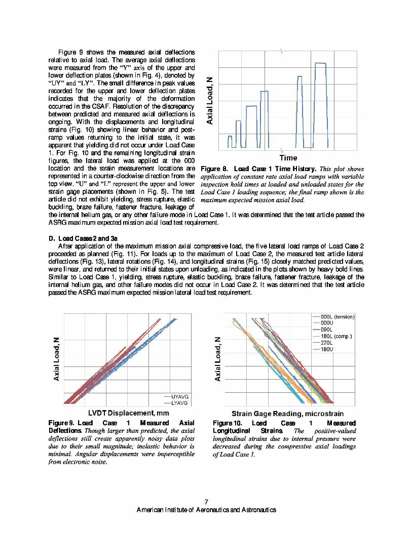
Figure 9 shows the measured axial deflectionsrelative to axial load. The average axial deflectionswere measured from the “Y” axis of the upper andlower deflection plates (shown in Fig. 4), denoted by“UY” and “LY”. The small difference in peak values Z,recorded for the upper and lower deflection plates 0indicates that the majority of the deformation o,occurred in the CSA F. Resolution of the discrepancy Jbetween predicted and measured axial deflections is
ICU
ongoing. With the displacements and longitudinal Qstrains (Fig. 10) showing linear behavior and post-ramp values returning to the initial state, it wasapparent that yielding did not occur under Load Case1. For Fig. 10 and the remaining longitudinal strainfigures, the lateral load was applied at the 000 Tim elocation and the strain measurement locations are Figure 8. Load Case 1 Time History. This plot showsrepresented in a counter-clockwise direction from the application of constant rate axial load ramps with variabletop view. “U” and “L” represent the upper and lower inspection hold times at loaded and unloaded states for thestrain gage placements (shown in Fig. 5). The test Load Case 1 loading sequence; the final ramp shown is thearticle did not exhibit yielding, stress rupture, elastic maximum expected mission axial load.buckling, braze failure, fastener fracture, leakage ofthe internal helium gas, or any other failure mode in Load Case 1. It was determined that the test article passed theASRG maximum expected mission axial load test requirement.
D. Load Cases 2 and 3aAfter application of the maximum mission axial compressive load, the five lateral load ramps of Load Case 2
proceeded as planned (Fig. 11). For loads up to the maximum of Load Case 2, the measured test article lateraldeflections (Fig. 13), lateral rotations (Fig. 14), and longitudinal strains (Fig. 15) closely matched predicted values,were linear, and returned to their initial states upon unloading, as indicated in the plots shown by heavy bold lines.Similar to Load Case 1, yielding, stress rupture, elastic buckling, braze failure, fastener fracture, leakage of theinternal helium gas, and other failure modes did not occur in Load Case 2. It was determined that the test articlepassed the ASRG maximum expected mission lateral load test requirement.
Figure 9. Load Case 1 M easured AxialDeflections. Though larger than predicted, the axialdeflections still create apparently noisy data plotsdue to their small magnitude; inelastic behavior isminimal. Angular displacements were imperceptiblefrom electronic noise.
Strai'ntGage Reading, aftrostraintFigure 10. Load Case 1 M easuredLongitudinal Strains. The positive-valuedlongitudinal strains due to internal pressure weredecreased during the compressive axial loadingsof Load Case 1.
7American Institute of Aeronautics and Astronautics

Figure 11. Load Case 2 Time History. This plotshows application of constant rate lateral load rampswith variable inspection hold times at loaded andunloaded states for the Load Case 2 loading sequence;the final ramp shown is the maximum expected missionlateral load.
Figure 12. Load Case 3a Time History. This plotshows application of constant rate lateral load rampswith variable inspection hold times at loaded andunloaded states for the Load Case 3a loadingsequence; all ramp peaks are at magnitudes greaterthan the maximum expected mission lateral load.
The data plots of Load Case 3a initially replicates Load Case 2, as the increased lateral load ramps of this caseare an experimental extension of the Load Case 2 ramps. Fig. 12 provides the load-time history for the sevenincreasing peak lateral load ramps of Load Case 3a; the last peak value was more than twice the Load Case 2 lateralload value. For the Load Case 3a loadings, the accumulation of inelastic deformation and strain (Figs. 13 to 15) isevident, as described in the Material Inelasticity Description (Section B) above. The average lateral deflectionsshown in Fig. 13 were measured from the “X” axis of the upper and lower deflection plates (shown in Fig. 4),denoted by “UX” and “LX”. For Fig. 14 and the remaining lateral rotation figures, the total rotation, CSA F rotation(ӨROT), and heater head rotation (ӨBEND) are shown. Even at the maximum lateral load of this case, the measuredresidual strain at the high stress area remained well below 0.2%, so it is assured that the defined yield strength (0.2%offset) was not reached. In addition, no other failure modes were observed for Load Case 3a. The peak load of LoadCase 3a was slightly greater than the predicted load to reach the defined yield stress at the most critical location ofthe test article.
Figure 13. Load Cases 2 and 3a MeasuredLateral Deflections. For the prefailure lateral loadcases, the measured lateral deflections closelymatched the predicted values, especially after the first20 to 30% of the maximum load shown. Very littleinelastic behavior is noted at and below the maximumexpected mission lateral load shown in bold.
Angu1'ar Di'Splaornent, deg reesFigure 14. Load Cases 2 and 3a MeasuredLateral Rotations. Similar to lateral deflectionsmeasured for the prefailure lateral load cases, themeasured lateral rotations matched the predictedvalues. Again, very little inelastic deformation isapparent at and below the maximum expected missionlateral load shown in bold.
8American Institute of Aeronautics and Astronautics
E. Load Case 3bTo determine the maximum lateral load-carrying
capacity of the test article and induce gross structuraldeformation or other failure modes, the internalpressure and axial compressive loads were maintainedas in Load Cases 2 and 3a, and a final lateral loadramp using the constant rate from previous testing was ^0', .
imposed on the test article. The end peak load for this (o)ramp was set to a very high value to cause test ytermination by attaining a predefined large lateral —'000L (tension)deflection. The load-time history for Load Case 3b is 011 —•000u
shown in Fig. 16, where a peak load was reached that —090L
is more than three times greater than the maximum • •• 270L (comp.)
r ^
expected mission lateral load. Lateral deflections (Fig. , •18ou
17), lateral rotations (Fig. 18), and longitudinal strains ^.Y : Load'fCasey2'Max..
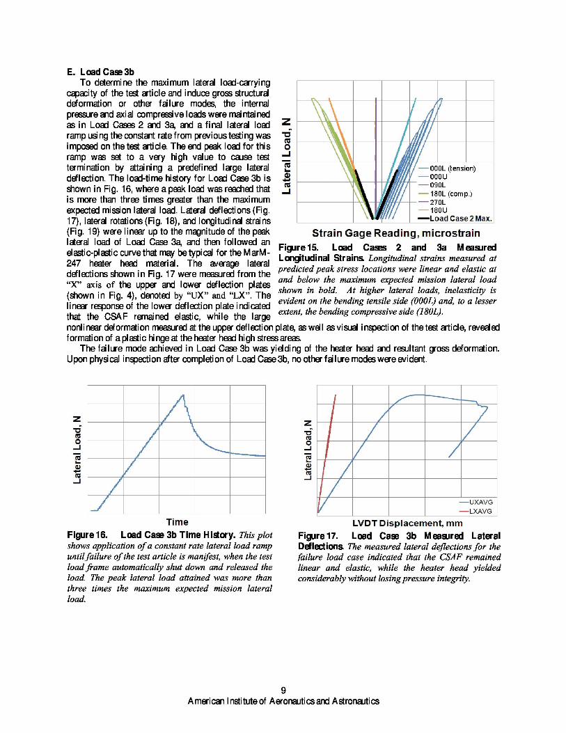
(Fig. 19) were linear up to the magnitude of the peak !Strai'n''G'ag'e.Read'irtg, mi'crostrainlateral load of Load Case 3a, and then followed an
Figure 15. Load Cases 2 and 3a Measuredelastic-plastic curve that may be typical for the MarM- Longitudinal Strains. Longitudinal strains measured at247 heater head material. The average lateral
predicted peak stress locations were linear and elastic atdeflections shown in Fig. 17 were measured from the“X” axis of the upper and lower deflection plates
and below the maximum expected mission lateral load
(shown in Fig. 4), denoted by “UX” and “LX”. The shown in bold. At higher lateral loads, inelasticity isevident on the bending tensile side (000L) and, to a lesser
linear response of the lower deflection plate indicatedthat the CSA F remained elastic, while the large
extent, the bending compressive side (180L).
nonlinear deformation measured at the upper deflection plate, as well as visual inspection of the test article, revealedformation of a plastic hinge at the heater head high stress areas.
The failure mode achieved in Load Case 3b was yielding of the heater head and resultant gross deformation.Upon physical inspection after completion of Load Case 3b, no other failure modes were evident.
Figure 16. Load Case 3b Time History. This plotshows application of a constant rate lateral load rampuntil failure of the test article is manifest, when the testload frame automatically shut down and released theload. The peak lateral load attained was more thanthree times the maximum expected mission lateralload.
Figure 17. Load Case 3b Measured LateralDeflections. The measured lateral deflections for thefailure load case indicated that the CSAF remainedlinear and elastic, while the heater head yieldedconsiderably without losing pressure integrity.
9American Institute of Aeronautics and Astronautics

Figure 18. Load Case 3b Measured LateralRotations. Similar to the measured lateral deflections,the lateral rotation measurements for the failure loadcase indicated that the CSAF remained linear andelastic, while the heater head yielded considerably.
'Strain G'ag'e Read i'ng,.N,trostrainFigure 19. Load Case 3b Measured LongitudinalStrains. Even at the highest stress area, thelongitudinal strains under the failure lateral loadingwere linear up to prior history load levels (shown inphantom), then followed the shape of a stress-straincurve typical for the heater head MarM-247 material.
V. Conclusion
The Heater Head Lateral Load Test was successful in directly supporting qualification of the Advanced StirlingConvertor (ASC)–E2 heater head analysis and validation of the design to meet launch requirements. The pressurizedtest article was exposed to anticipated maximum axial compressive and maximum lateral loads during an AdvancedStirling Radioisotope Generator (ASRG) launch, and reliably sustained these load conditions. After demonstratingthat the test article did not fail under flight-like loads, the test continued with increased lateral loading until theheater head yielded, sustaining more than three times the maximum expected mission lateral load while maintainingpressure integrity. This test result validated the capability of the heater head to meet the launch load requirementswith sufficient margin.
AcknowledgmentsThis work is funded through the NASA Science Mission Directorate. Any opinions, findings, and conclusions or
recommendations expressed in this article are those of the authors and do not necessarily reflect the views of theNational Aeronautics and Space Administration. The authors wish to acknowledge the people who made this effortpossible including Jeff Schreiber, Ralph Pawl i k, Wayne Wong, Frank B remenour, and Sreeramesh Kal l uri of NASAGlenn Research Center, as well as Debbie Kuhlman and Greg McNelis of Lockheed Martin for their counsel andsupport throughout this test. The authors also thank Ms. Angela Coates of the University of Akron for her real-timeevaluation of test article response and enthusiastic analysis of the voluminous post-test data.
References1Chan, J., Wood, J.G., and Schreiber, J.G., “Development of Advanced Stirling Radioisotope Generator for Space
Exploration,” proceedings of Space Technology and Applications International Forum (STAI F 2007), edited by M.S. El-Genk,A I P Conference Proceedings 880, pp. 615–623, 2007.
10American Institute of Aeronautics and Astronautics