Embed Size (px)
Citation preview
Journal of Computational Applied Mechanics 2020, 52(1)
DOI: 10.22059/jcamech.2021.311144.564
RESEARCH PAPER
Lateral Safety Enhancement in a full Dynamic Vehicle Model
Based on Series Active Variable-Geometry Suspension Amin Najafi and Masoud Masih-Tehrani*
School of Automotive Engineering, Iran University of Science and Technology
Abstract Today, the importance of providing safety and stability while pay attention to the ride comfort and
providing road holding is of paramount importance. This issue has become more important due to the
many accidents related to vehicle rollover. In this article, an attempt has been made to reduce the risk of rollover prevention of the vehicle while pay attention to the needs of the occupant and the road. In this
research, an attempt has been made to reduce the overall acceleration of the GT vehicle by using a series
of active variable geometry suspensions and by using a variety of control strategies such as Fuzzy PID, LQR, Sliding mode. In previous works, PID and Skyhook controllers have been used. However, in this
study, the choice of the controllers is based on attention to accuracy and optimization while pay attention
to control aims. This study was performed in conditions of severe asymmetric roughness and cornering
maneuvers. The examination of the results shows an improvement of more than 20% for the goal of vehicle stability while providing other suspension goals. This performance improvement occurs with
the effect of suspending variable geometry along with the use of a suitable controller. It should also be
noted that the improvement achieved by consuming energy is far less than other suspensions, which is the strength of the research.
Keywords: Series active variable-geometry suspension, SAVGS, Rollover prevention, LQR, Sliding
mode, Fuzzy
Introduction
Given the high importance of vehicle overturning in recent years and the spread of concern in
this regard, the issue of preventing lateral overturning of the vehicle has become a paramount
concern [1]. Therefore, it is necessary and crucial to developing the vehicle rollover moot point
and anti-rollover control system to improve the roll stability and avoid rollovers. This goal
largely depends on the design and performance of the vehicle's suspension. On the other hand,
today, given the importance of the energy issue, this point should be taken into account in
designing the suspension system [2] [3]. Besides, the primary function of the suspension system
should be considered in creating suitable ride comfort while the road holding [4, 5].
The use of an active suspension system that provides instantaneous control of the amount of
stiffness and dumping of the system primarily covers the above objectives [1, 6]. The biggest
problem of active suspensions is their high energy consumption. The series variable-geometry
suspension system by changing the position and angle of the suspension stratum with the help
of the added link and a servo motor covers the mentioned need [4, 7].
In previous works, many procedures were used for vehicle roll prevention, such as active
differential braking system [8-10], active steering [11, 12], active and semi-active suspension
[13-15], and together with active suspension and differential braking [3, 16, 17].
This article uses a series active variable geometry suspention to study a ground tour (GT)
vehicle in certain conditions. In this study, a recovery control strategy has been used in the
vehicle's dynamic response. Given the importance of the issue mentioned above and the high
* Corresponding author e-mail: [email protected]

Journal of Computational Applied Mechanics 2021, 52(1) 155
casualties of vehicle overturning, extensive research has been done in this field. However, the
main differences and innovations of the study are as follows:
Paying attention to the majority of the vehicle's dynamic parameters using the full vehicle
model instead of the one-quarter model
The use of a new type of suspension system that has not been studied extensively in the
field of vehicle rolls
Paying attention to performance improvement in several areas by choosing the type of
the suspension and operator in addition to providing dynamic response purposes, reduces
energy consumption
Possibility to add driving maneuvers to the vehicle's mathematical model and use hard
condition maneuvers (combining road conditions and environmental conditions) that
will lead to the realization of the study.
Implement a variety of modern and classic controllers that provide the conditions for
multifunctional and more comprehensive studies
For this purpose, first, a complete model providing the dynamic characteristics of the vehicle
and the conditions for performing the test on the designed model will be discussed is designed
(section 2). Then, a complete description of the control methods used (section 3) to achieve the
appropriate system response will be provided. In the last section, the results will be described,
and the results of the work will be done.
Modeling of a Full Vevicle Model
The mathematical model is used to explain the dynamic states of the vehicle, and the suspension
is the existing model of the Cheng reference paper [18]. This model of vehicle mode space has
10 inputs and 15 outputs given in equation 1.
The details of how to calculate the state space matrices with the exact value of the components
along with the vibrational and force relations governing the base are explained in the reference
[9].
1 2 3 41 2 3 4
1 2 3 4 1 2 3 4 1 2 3 4
, , ,[ , , , , , , ]
[ , , , , , , , , , , , , , , ]
SL SL SL SL
T
T
p r r r r r
t t t t s s s s s s s s
u T T z z z z
y l l l l z z z z Z l l l l
(1)
This model has rough road inputs and external torques on the vehicle, which the road
roughness assumed in the research will be from a standard random road type C and E. These
two types of road roughness are obtained by considering the car speed of 100 km/h and using
the rules of Wong [19, 20] and are applied asymmetrically to both sides of the vehicle. Figure
1 shows the asymmetric unevenness diagram generated as a random standard. Where the left
side of the vehicle passes with type C roughness and the right side with more severe type E
roughness and the car is in an asymmetric roughness.
To simulate Tp/Tr (to excite the rotational movements) as 1 and 2 inputs, The spring travel
difference between the front and rear suspension and the left and right of the vehicle is
calculated. Then by calculating the suspension force resulting from the compression difference
and considering the distance to the center of mass and installation ratio, the torque values are
calculated [21].
(1,2) 1 2
(3,4) 3 4
1 2 3 4
( )
( )
p s s
p s s
sf
sr
p p p p p
T l or l K wheelbase Weight distribution
T l or l K wheelbase Weight distribution
T T T T T
(2)
156 Najafi and Masih-Tehrani
Figure 1. Road disturbance on type C and E ISO random road
The equation 2 shows the calculated pitching torque of each corner of the vehicle, and we
can get the total Tp of the vehicle. Similarly, the amount of this torque for the vehicle roll can
be obtained.
Table 1 lists the values of important and influential parameters in the design of the vehicle
model, which are obtained by using the Ferrari F430 vehicle catalog.
Table 1. Parameters of the model
Number Parameter Value Unit
1 Wb 2.6 m
2 CMh 450 mm
3 / sm m 1325/1525 kg
4 (F/R)disW 57/43 %
5 (F/R)sk 92/158 N/mm
6 (F/R)tk 275 N/mm
7 (F/R)T 1.405/1.43 m
8 /xx yyI I 300/1500 kg.m2
9 (F/R)usm 47.5/52.5 kg
10 Φ ΦK / C 189506/6364 N/rad , N.s/rad
One of the main differences between the existing model and the reference article is the
possibility of adding different maneuvers (desired maneuver output information or
simultaneous stimulation of the maneuver in dynamic analysis software) to achieve a more
comprehensive study of road conditions and control objectives.
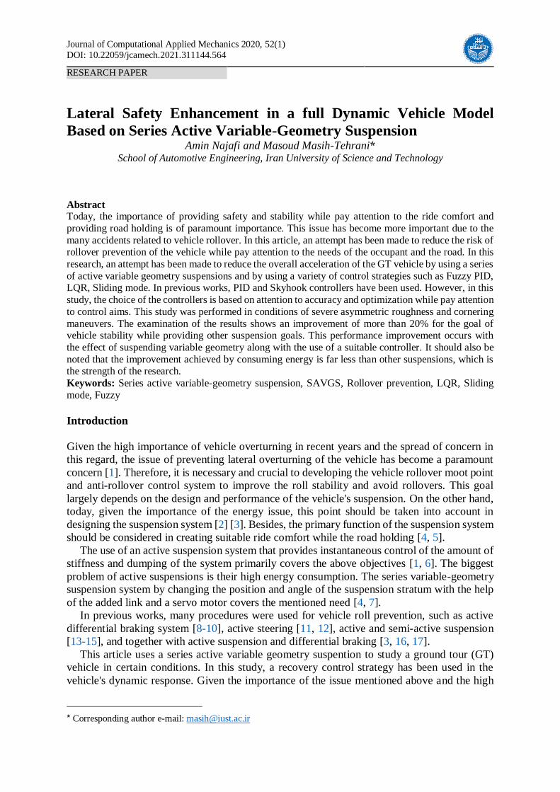
The crosswind maneuver consists of a path where the vehicle is affected by lateral winds
while traveling at speeds of 100 km/h. The purpose of this work is to make the wind test have
a high impact on the dynamics of the system and to face the most challenging conditions
according to the type of rough road. The wind speed terms of time during the test diagram are
given in figure 2, which shows that a high wind with variable wind conditions has been used.
Journal of Computational Applied Mechanics 2021, 52(1) 157
Figure 2. Global wind speed in the crosswind test
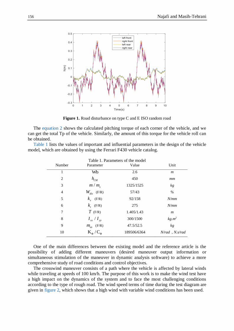
Validation of the model
As mentioned earlier, the model used is the Cheng reference model, which has already been
verified. However, since the front torque and roll of the vehicle have been calculated separately
and given to the model, it is necessary to verify again with the model.
As can be seen in figure 3, the amount of acceleration and tire deflection of the vehicle in
the passive state is very close to its value in the reference article, and the reason for its small is
more complicated due to the change in problem conditions for testing.
(a)
(b) (c)
Figure 3. Vehicle responses of reference and designed model (a) Pitch angular acceleration (b) Tire deflection (c) Bounce acceleration
158 Najafi and Masih-Tehrani
Table 2 shows the numerical values obtained from the results of the reference model in
comparison with the model designed in passive mode under a road by type A at speed of 100
km/h.
Table 2. numerical values for validation
Parameter Reference
value Generated value Unit Error
Max Pitch acc 0.83 0.85 Rad/s2 4%
Min Pitch acc -0.94 -0.99
Max Roll acc 2.2 2.1 Rad/s2 4.5%
Min Roll acc -2 -2.1
CG max acc 2.95 3 m/s2 1.3%
CG Min acc -2.98 -3.01
Tire Max deflection 2.95 2.98 cm 1.6%
Controller Scheme
The primary purpose of this work is to design a control process based on the full vehicle
dynamics to reduce the amount of roll to achieve the desired conditions to avoid the rollover in
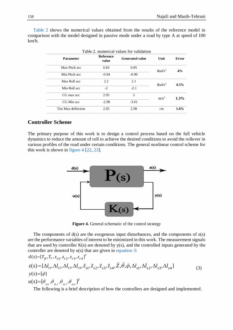
various profiles of the road under certain conditions. The general nonlinear control scheme for
this work is shown in figure 4 [22, 23].
Figure 4. General schematic of the control strategy
The components of d(s) are the exogenous input disturbances, and the components of z(s)
are the performance variables of interest to be minimized in this work. The measurement signals
that are used by controller K(s) are denoted by y(s), and the controlled inputs generated by the
controller are denoted by u(s) that are given in equation 3:
1 2 3 4
2 3 4
1 2 3 4
1
1 2 3 4 1 2 3 4
, , ,
( ) [ , , , , , ]
]( ) [
( ) [ , , , , , , , , , , , , , , ]
( ) [ ]SL SL SL SL
T
r r r
t t t t
T
p r r
s s s s s s s s
d s T T z z z z
y s
z s l l l l z z z z Z l l l
u s
l
(3)
The following is a brief description of how the controllers are designed and implemented.

Journal of Computational Applied Mechanics 2021, 52(1) 159
Fuzzy PID Controller
The first controller used in this research is the use of Fuzzy PID controller. The controller has
been used in previous research. In this paper, a fuzzy generator is used to determine the values
of the PID controller coefficients, which are shown in figure 5 of the input and output
memberships [24-26].
Figure 5. Memberships of inputs and outputs
The control rules between input and output are also given in another article is being
published by the authors of this article, that the value range and forms of memberships and rules

160 Najafi and Masih-Tehrani
of this controller have been changed to appropriate values after trial and error and compliance
with the references [27].
LQR Controller
Fuzzy PID controller is responsive to many conditions of the suspension due to its robustness
property. However, a controller that is useful for state-space design. With the feature of being
optimal is needed [28, 29]. To achieve this aim, an LQR controller is designed and used to
compare with two controller strategies.
LQR controller design is for linear systems by generating system states and using them to
create a controlling factor. Therefore, before designing the controller, one must design an
observer [30].
( ) ( ) ( )
( ) ( ) ( )
( ) ( )
x t Ax t Bu t
y t Cx t Du t
u t Ke t
(4)
Due to the design of the observer, the values related to the road design, and also the
ineffectiveness of the maneuvers performed, the mentioned values must be entered into the
system as follows: ( ) ( ) ( )
( ) ( ) ( )m
e t r t x t
u t u t d t
(5)
The observer designed in the article is a combination of system inputs and outputs, taking
into account the initial conditions and specific values of the system.
The K is evaluated concerning the system dynamics for the minimum value of the quadratic
performance index j as specified in the equation 6 [31].
0
[ ( ) ( ) ( ) ( )]T Tj x t Qx t u t Ru t dt
(6)
One of the categories that LQR controller design depends on is choosing the right values for
Q and R matrices.
For this purpose, first of all, by referring to the articles that had worked in the field of vehicle
rolls, the mentioned matrices were defined.
After that, considering the suggested values of the existing articles [32] and rules for
selecting the range of high matrices, we reached the following values that are given in equation
7 , with several changes. 3
14 14
10 10
10
[1]
Q C C
R diag
(7)
Sliding Mode Controller
After implementing the two mentioned controllers, the slider mode controller will be designed
to create an optimal and resistant mode for the problem. In this controller that the general view
of which is shown in figure 6, will quantify the output of the controller in the optimal range by
receiving the measured error resulting from the output value of the system and the reference
value of zero and the time derivative of the error [33].
Before defining and implementing the basic rules for the slider mode controller mentioned,
first, the changes in the parameters used in table 3 are given [24].

Journal of Computational Applied Mechanics 2021, 52(1) 161
Figure 6. Simulink diagram from the sliding mode controller
Table 3. Sliding mode control coefficient design table
Parameter Equivalent Parameter
ry 0
dy
r de y y 0e
S e e ( )S
sgn( )equ u k S ( , , , , )SMCu SMC e e k
In the equation 8 and equation 9, the basic rules of controller design are given, which have
been implemented with the authorities after verification.
sat( ) sgn( )
sat( )
s e e
s psi s sif
selse spsi
(8)
Values related to the design of the controller operation are obtained from the references [34]
and after finding the relationship between the inputs and outputs of the controller and placing
them in the governing equations [35].
( , , , , )output SMC e e k psi (9)
Results and Discussion
In this section, the results of the behavior of the vehicle model will be discussed. For this
purpose, the vehicle traveled with the said conditions and mentioned in the maneuver and road
conditions for 10 seconds, and the control methods discussed are applied to the model. The
results of the vehicle oscillation response in each of the factors are compared with its value
under the same conditions without the use of SAVGS.
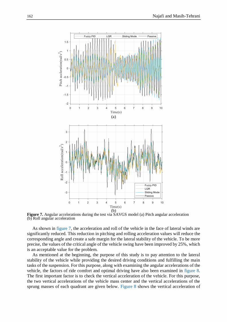
Figure 7 shows the values obtained from the vehicle's angular acceleration response. The
reason for the importance of these two values is to ensure the lateral security of the vehicle and
prevent rollover.
162 Najafi and Masih-Tehrani
(a)
(b)
Figure 7. Angular accelerations during the test via SAVGS model (a) Pitch angular acceleration (b) Roll angular acceleration
As shown in figure 7, the acceleration and roll of the vehicle in the face of lateral winds are
significantly reduced. This reduction in pitching and rolling acceleration values will reduce the
corresponding angle and create a safe margin for the lateral stability of the vehicle. To be more
precise, the values of the critical angle of the vehicle swing have been improved by 25%, which
is an acceptable value for the problem.
As mentioned at the beginning, the purpose of this study is to pay attention to the lateral
stability of the vehicle while providing the desired driving conditions and fulfilling the main
tasks of the suspension. For this purpose, along with examining the angular accelerations of the
vehicle, the factors of ride comfort and optimal driving have also been examined in figure 8.
The first important factor is to check the vertical acceleration of the vehicle. For this purpose,
the two vertical accelerations of the vehicle mass center and the vertical accelerations of the
sprung masses of each quadrant are given below. Figure 8 shows the vertical acceleration of

Journal of Computational Applied Mechanics 2021, 52(1) 163
the vehicle mass center (bounce acceleration) and the sprung mass acceleration of each corner
of the vehicle.
Figure 8. Vehicle CG vertical acceleration response and Sprung mass acceleration response in each corner of the vehicle
As can be seen, the parameters affecting the comfort of the vehicle have also been improved
along with the focus on the angular acceleration of the vehicle. This achievement is of great
value, which achieved several desirable goals by using a special suspension system and using
the appropriate control method while reducing the energy consumption of the operator and the
vehicle. This means that if a lateral disturbing factor such as strong winds that disrupts the
stability of the vehicle is applied to the model and the model enters a very high and asymmetric
roughness at a very high speed, preserve a significant improvement in lateral stability. More of
them, the vehicle does not loss of ride comfort.
Now that the stability of the vehicle and the comfort of the passenger have been examined,
the road holding and the favorable driving conditions are being considered. The reason for this
is due to the nature of the suspension system and the coverage of the suspension targets in a
different frequency range and instantaneously. The influential factor in the mentioned factor is
the instantaneous compression of the vehicle tire. Figure 9 shows the instantaneous oscillation
response of a vehicle tire to road roughness and vertical load application.
Figure 9. Deflection value per each vehicle tire

164 Najafi and Masih-Tehrani
As can be seen, as in the previously studied variables, there is a slight improvement in the
compression of the tire in each corner of the vehicle with the assumption of one-way wind and
severe asymmetric unevenness, which indicates that the model used with the assumptions and
designs mentioned all parameters improved the vehicle as a whole. The numerical and exact
values of the vehicle response and the diagrams are shown in table 4.
Table 4. The numerical value of system responses
Parameter
Passive Fuzzy PID LQR Sliding Mode
Unit Value Value Change Value Change Value Change
Max Pitch acc 1.815 1.47 19.01% 1.595 12.12% 1.754 3.36% Rad/s2
Min Pitch acc -1.859 -1.518 18.34% -1.332 28.35% -1.809 2.69%
Max Roll acc 3.286 1.911 41.84% 2.25 31.53% 2.108 35.85% Rad/s2
Min Roll acc -3.285 -1.798 45.27% -2.169 33.97% -1.719 47.67%
Max CG acc 3.303 2.159 34.64% 2.601 21.25% 2.145 35.06% m/s2
Min CG acc -4.698 -3.363 28.42% -3.863 17.77% -3.34 28.91%
Max Tire deflection 0.008 0.0058 27.5% 0.0054 32.5% 0.006 25%
cm Min Tire
deflection -0.00009 -0.0057 36.7% -0.0037 48.89% -0.006 33.33%
Max Sprung mass acc 2.785 2.195 21.18% 2.108 24.31% 2.582 7.29 m/s2
Min Sprung mass acc -3.045 -2.051 32.64% -2.543 16.49 -2.436 20%
As shown in table 4, the rate of improvement of the variables in all vehicle output parameters
is in the range of 10 to 50%, which varies according to the nature of the variable and the
controller used. The noteworthy point is the reduction of high energy consumption and low
manufacturing complexity while operating the improvement, which promises the development
of this suspension system and conducting more accurate and comprehensive research.
Conclusions
This study presents the technology of a new suspension system with the right control strategy
to the roll prevention of vehicle that effected in challenging conditions of maneuvers. This
vehicle model includes the effects of the road profile and test conditions. These effects are made
significant-high rollover risks. In summary, the work done in the three main sections is as
follows:
Suspension and vehicle modeling with its effects
Define maneuvering and implementation on the complete vehicle model
Definition of modern and classic control strategy and the possibility of the
implementation for multi-parameter control
With this condition, a significant improvement of about 35% has been achieved to prevent
overturning. This performance improvement has occurred because due to the use of the
SAVGS system, the vehicle's energy consumption has been dramatically reduced compared to
the active suspension. This improvement in overturning and roll performance is of great
importance by reducing energy consumption and improving vertical acceleration parameters
and occupant ride comfort and road holding.
In conclusion, the improvement of the vehicle's roll parameters is about 40%, and the
comfort and adhesive parameters are about 25% while reducing the energy consumption of the
suspension.

Journal of Computational Applied Mechanics 2021, 52(1) 165
In future research, it is suggested that the existing model be linked to automotive analysis
software and that the values of the variables be taken from the software simultaneously. By
doing this, the used model can be implemented on all vehicles . Also, the possibility of
performing laboratory tests and using laboratory operators to make the model more really is of
paramount importance. In future work, it is possible to study different objectives of variety
vehicles by using the existing model, and it is also possible to implement more stability
maneuvers such as fishhook and double lane change, etc. in the model.
.
References
[1] M. R. Pfeiffer, Analysis of Pedestrian Injuries by Passenger Vehicle Model Year, United
States. Department of Transportation. National Highway Traffic Safety …, pp. 2020.
[2] M. Ataei, A. Khajepour, S. Jeon, Model predictive rollover prevention for steer-by-wire
vehicles with a new rollover index, International Journal of Control, Vol. 93, No. 1, pp.
140-155, 2020.
[3] B. Mashadi, M. Mokhtari-Alehashem, H. Mostaghimi, Active vehicle rollover control
using a gyroscopic device, Proceedings of the Institution of Mechanical Engineers, Part D:
Journal of Automobile Engineering, Vol. 230, No. 14, pp. 1958-1971, 2016.
[4] Y. Chen, Modeling, Control, and Design Study of Balanced Pneumatic Suspension for
Improved Roll Stability in Heavy Trucks, Thesis, Virginia Tech, 2017.
[5] M. Baghani, M. Mohammadi, A. Farajpour, Dynamic and stability analysis of the rotating
nanobeam in a nonuniform magnetic field considering the surface energy, International
Journal of Applied Mechanics, Vol. 8, No. 04, pp. 1650048, 2016.
[6] H. Li, Y. Zhao, H. Wang, F. Lin, Design of an improved predictive LTR for rollover
warning systems, Journal of the Brazilian Society of Mechanical Sciences and Engineering,
Vol. 39, No. 10, pp. 3779-3791, 2017.
[7] Y. Chen, M. Ahmadian, A. Peterson, Pneumatically balanced heavy truck air suspensions
for improved roll stability, 0148-7191, SAE Technical Paper, pp. 2015.
[8] B.-C. Chen, H. Peng, Differential-braking-based rollover prevention for sport utility
vehicles with human-in-the-loop evaluations, Vehicle system dynamics, Vol. 36, No. 4-5,
pp. 359-389, 2001.
[9] L. Li, Y. Lu, R. Wang, J. Chen, A three-dimensional dynamics control framework of
vehicle lateral stability and rollover prevention via active braking with MPC, IEEE
Transactions on Industrial Electronics, Vol. 64, No. 4, pp. 3389-3401, 2016.
[10] S. Solmaz, M. Akar, R. Shorten, Adaptive rollover prevention for automotive vehicles with
differential braking, IFAC Proceedings Volumes, Vol. 41, No. 2, pp. 4695-4700, 2008.
[11] S. Solmaz, M. Corless, R. Shorten, A methodology for the design of robust rollover
prevention controllers for automotive vehicles with active steering, International Journal
of Control, Vol. 80, No. 11, pp. 1763-1779, 2007.
[12] J. Wu, Y. Zhao, X. Ji, Y. Liu, L. Zhang, Generalized internal model robust control for
active front steering intervention, Chinese Journal of Mechanical Engineering, Vol. 28, No.
2, pp. 285-293, 2015.
[13] M. Kamal, T. Shim, Development of active suspension control for combined handling and
rollover propensity enhancement, 0148-7191, SAE Technical Paper, pp. 2007.
[14] S. Solmaz, Switched stable control design methodology applied to vehicle rollover
prevention based on switched suspension settings, IET control theory & applications, Vol.
5, No. 9, pp. 1104-1112, 2011.

166 Najafi and Masih-Tehrani
[15] S. Yim, Y. Park, K. Yi, Design of active suspension and electronic stability program for
rollover prevention, International journal of automotive technology, Vol. 11, No. 2, pp.
147-153, 2010.
[16] S. Yim, Design of a robust controller for rollover prevention with active suspension and
differential braking, Journal of mechanical science and technology, Vol. 26, No. 1, pp. 213-
222, 2012.
[17] S. R. Asemi, M. Mohammadi, A. Farajpour, A study on the nonlinear stability of
orthotropic single-layered graphene sheet based on nonlocal elasticity theory, Latin
American Journal of Solids and Structures, Vol. 11, No. 9, pp. 1515-1540, 2014.
[18] C. Cheng, S. A. Evangelou, Series Active Variable Geometry Suspension Robust Control
Based on Full-Vehicle Dynamics, Journal of Dynamic Systems, Measurement, and
Control, Vol. 141, No. 5, 2019.
[19] P. Múčka, Simulated road profiles according to ISO 8608 in vibration analysis, Journal of
Testing and Evaluation, Vol. 46, No. 1, pp. 405-418, 2017.
[20] J. Wong, Vehicle Ride Characteristics, Theory of Ground Vehicles, pp. 348-392, 1993.
[21] S. Nazemi, M. Maish-Tehrani, Series Active Variable Geometry Suspension Fuzzy-Logic
Control for a GT Car on a Rough Road.
[22] I. Cvok, J. Deur, H. E. Tseng, D. Hrovat, Comparative Performance Analysis of Active
and Semi-active Suspensions with Road Preview Control, in Proceeding of, Springer, pp.
1808-1818.
[23] M. R. Ha’iri-Yazdi, A. Safaei, V. Esfahanian, M. Masih-Tehrani, Design of the Online
Optimal Control Strategy for a Hydraulic Hybrid Bus, Journal of Control, Vol. 8, No. 1,
pp. 1-10, 2014.
[24] M. Shirzadeh, M. H. Shojaeefard, A. Amirkhani, H. Behroozi, Adaptive fuzzy nonlinear
sliding-mode controller for a car-like robot, in Proceeding of, IEEE, pp. 686-691.
[25] A. Najafi, A. Amirkhani, K. Mohammadi, A. Naimi, A novel soft computing method based
on interval type-2 fuzzy logic for classification of celiac disease, in Proceeding of, IEEE,
pp. 257-262.
[26] A. Farajpour, A. Rastgoo, M. Mohammadi, Vibration, buckling and smart control of
microtubules using piezoelectric nanoshells under electric voltage in thermal environment,
Physica B: Condensed Matter, Vol. 509, pp. 100-114, 2017.
[27] C. Conker, M. K. Baltacioglu, Fuzzy self-adaptive PID control technique for driving HHO
dry cell systems, International Journal of Hydrogen Energy, 2020.
[28] J. Marzbanrad, Y. HOJAT, H. ZOHOUR, S. Nikravesh, Optimal preview control design
of an active suspension based on a full car model, 2003.
[29] M. Mohammadi, M. Hosseini, M. Shishesaz, A. Hadi, A. Rastgoo, Primary and secondary
resonance analysis of porous functionally graded nanobeam resting on a nonlinear
foundation subjected to mechanical and electrical loads, European Journal of Mechanics-
A/Solids, Vol. 77, pp. 103793, 2019.
[30] M. A. Khan, M. Abid, N. Ahmed, A. Wadood, H. Park, Nonlinear Control Design of a
Half-Car Model Using Feedback Linearization and an LQR Controller, Applied Sciences,
Vol. 10, No. 9, pp. 3075, 2020.
[31] G. F. Franklin, J. D. Powell, M. L. Workman, 1998, Digital control of dynamic systems,
Addison-wesley Reading, MA,
[32] B. Xu, C. Song, Y. Tan, Research on LQR Control of Magnetic Suspension Active
Vibration Isolation System Based on Multi-population Genetic Algorithm, in Proceeding
of, Springer, pp. 672-688.

Journal of Computational Applied Mechanics 2021, 52(1) 167
[33] W. Perruquetti, J.-P. Barbot, 2002, Sliding mode control in engineering, CRC press,
[34] Y. Chen, S. Zhang, E. Mao, Y. Du, J. Chen, S. Yang, Height stability control of a large
sprayer body based on air suspension using the sliding mode approach, Information
Processing in Agriculture, Vol. 7, No. 1, pp. 20-29, 2020.
[35] C. Zhou, X. Liu, F. Xu, W. Chen, Sliding Mode Switch Control of Adjustable Hydro-
Pneumatic Suspension based on Parallel Adaptive Clonal Selection Algorithm, Applied
Sciences, Vol. 10, No. 5, pp. 1852, 2020.