Embed Size (px)
Citation preview
September 2012 704-0214-210 Revision A
MAINTENANCE AND SAFETY MANUAL
for Turning Centers
ii - Maintenance and Safety Manual 704-0214-210 Turning Centers Maintenance and Safety
The information in this document is subject to change without notice and does not represent a commitment on the part of Hurco Companies, Inc. (Hurco). The software described in this document is furnished under the License Agreement to customers. It is against the law to copy the software on any medium except as specifically allowed in the license agreement. The purchaser may make copies of the software for backup purposes. No part of this document may be reproduced or transmitted in any form or by any means, electronic or mechanical, including photocopying, for any purpose without the express written permission of the Hurco machine tool owner.
Hurco Manufacturing Company reserves the right to incorporate any modification or improvements in machines and machine specifications which it considers necessary, and does not assume any obligation to make any said changes in machines or equipment previously sold.
Hurco products and services are subject to Hurco’s then current prices, terms, and conditions, which are subject to change without notice.
© 2012 Hurco Companies, Inc. All rights reserved.
Patents: U.S. Patents B14,477,754; 5,453,933; Canadian Patent 1,102,434; Japanese Patents 1,649,006 and 1,375,124; other Patents pending.
Hurco, Max, Ultimax, and WinMax are Registered Trademarks of Hurco Companies, Inc.
AutoCAD, Autodesk, and DXF are registered trademarks of Autodesk, Inc.
MS-DOS, Microsoft, and Windows are registered trademarks of Microsoft Corporation.
Many of the designations used by manufacturers and sellers to distinguish their products are claimed as trademarks. Hurco has listed here all trademarks of which it is aware. For more information about Hurco products and services, contact:
Hurco Companies, Inc. One Technology WayP.O. Box 68180Indianapolis, IN 46268-0180Tel (317) 293-5309 (products)
(317) 298-2635 (service)Fax (317) 328-2812 (service)
For Hurco subsidiary contact information, go to Hurco’s Web site:www.hurco.com
Turning Centers Maintenance and Safety 704-0214-210 Maintenance Checklist — iii
MAINTENANCE CHECKLIST
Daily (Every 8 - 10 Hours) Perform operational checks. . . . . . . . . . . . . . . . . . . . . . . . . . . . . . . . . . . 4 - 2 Check the USB port. . . . . . . . . . . . . . . . . . . . . . . . . . . . . . . . . . . . . . . . 4 - 3 Check and maintain all lubricant levels. . . . . . . . . . . . . . . . . . . . . . . . . . . 4 - 3 Grease the chuck. . . . . . . . . . . . . . . . . . . . . . . . . . . . . . . . . . . . . . . . . 4 - 9 Maintain the spindle chiller system (if equipped). . . . . . . . . . . . . . . . . . . . 4- 10 Check the spindle chiller (if equipped) working environment, ventilation,
and ambient temperature. . . . . . . . . . . . . . . . . . . . . . . . . . . . . . . . . . . . 4- 12 Check the FRL unit air pressure. . . . . . . . . . . . . . . . . . . . . . . . . . . . . . . . 4- 19 Check the Filter and Regulator Unit air pressure for
TM models. . . . . . . . . . . . . . . . . . . . . . . . . . . . . . . . . . . . . . . . . . . . . . 4- 19 Check the auto moisture drain on FRL. . . . . . . . . . . . . . . . . . . . . . . . . . . 4- 20 Check the coolant level every day at the start of operation. . . . . . . . . . . . . 4- 25 Clean the coolant collector filter. . . . . . . . . . . . . . . . . . . . . . . . . . . . . . . 4- 26 Clean the chip conveyor tank (if equipped) chip screens. . . . . . . . . . . . . . 4- 36 Inspect the enclosure windows. . . . . . . . . . . . . . . . . . . . . . . . . . . . . . . . 4- 38
Weekly (Every 40 - 50 Hours) Clean the filter inside the heat exchanger. . . . . . . . . . . . . . . . . . . . . . . . . 4 - 3 Inspect the chiller solution level (if equipped). . . . . . . . . . . . . . . . . . . . . . 4- 10 Inspect the spindle chiller tank air filter and water filter (if equipped). . . . . 4- 10 Check the auto moisture drain on the Filter and Regulator Unit for
TM models. . . . . . . . . . . . . . . . . . . . . . . . . . . . . . . . . . . . . . . . . . . . . . 4- 20 Clean the coolant filters. . . . . . . . . . . . . . . . . . . . . . . . . . . . . . . . . . . . . 4- 25
Monthly (Every 150-200 Hours) Inspect conduit, connectors, cabling, and external wiring. . . . . . . . . . . . . . 4 - 3 Add a rust preventative to the Autolube system. . . . . . . . . . . . . . . . . . . . 4 - 5 Maintain the autolube fluid level and check the filler filter screen. . . . . . . . 4 - 6 Check the turret oil level. . . . . . . . . . . . . . . . . . . . . . . . . . . . . . . . . . . . 4 - 9 If compressed air is used, remove the drain plug and open the
Steady Rest drain. . . . . . . . . . . . . . . . . . . . . . . . . . . . . . . . . . . . . . . . . 4- 35 Inspect limit switches and dog fasteners. . . . . . . . . . . . . . . . . . . . . . . . . 4- 37 Perform a spindle run-in. . . . . . . . . . . . . . . . . . . . . . . . . . . . . . . . . . . . . 4- 38
Do not attempt to access the machine enclosure while machine power is on. Observe proper lock-out/tag-out procedures before performing any maintenance inside the machine enclosure.
iv - Maintenance Checklist 704-0214-210 Turning Centers Maintenance and Safety
Every 3 Months (Every 500 Hours) Check the FRL air filter element regularly and replace it for
TMX and TMM models. . . . . . . . . . . . . . . . . . . . . . . . . . . . . . . . . . . . . . . 4- 20 Clean or replace the air filter element on the Filter and Regulator Unit for
TM models. . . . . . . . . . . . . . . . . . . . . . . . . . . . . . . . . . . . . . . . . . . . . . . 4- 20 Drain moisture from the lines of the Filter and Regulator Unit and FRL. . . . . 4- 20 Replace coolant and coolant filters. . . . . . . . . . . . . . . . . . . . . . . . . . . . . . 4- 25 Inspect and clean the TMX coolant valve located on the turret. . . . . . . . . . . 4- 26 Inspect and clean the TMM coolant valve located inside the turret. . . . . . . . . 4- 30 Clean the chip conveyor tank (if equipped). . . . . . . . . . . . . . . . . . . . . . . . 4- 36 Measure the ground impedance (resistance to true earth). . . . . . . . . . . . . . 4- 37
Every 6 Months (Every 1000 Hours or as stated) Check the grease in the live-tooling turret gear box. . . . . . . . . . . . . . . . . . 4- 32 Clean the back of the live-tooling turret disk and the gasket. . . . . . . . . . . . 4- 33 Check the live-tooling turret power intake rotary seal. . . . . . . . . . . . . . . . . 4- 34 Verify the machine is sitting level. . . . . . . . . . . . . . . . . . . . . . . . . . . . . . . 4- 37
Annually (Every 2000 Hours or as stated) Clean the autolube reservoir tank and suction filter. . . . . . . . . . . . . . . . . . . 4 - 6 Flush, clean, and refill the spindle chiller tank (if equipped). . . . . . . . . . . . . 4- 11 Drain and replace the fluid and filter in the hydraulic tank. . . . . . . . . . . . . . 4- 21 Disassemble and clean the Steady Rest. . . . . . . . . . . . . . . . . . . . . . . . . . . 4- 35 Check the Steady Rest safety valve. . . . . . . . . . . . . . . . . . . . . . . . . . . . . . 4- 35
Turning Centers Maintenance and Safety 704-0214-210 Table of Contents — v
TABLE OF CONTENTS
Maintenance and Safety Manual
Maintenance Checklist . . . . . . . . . . . . . . . . . . . . . . . . . . . . . . . . . . . . . . . . iii
Documentation Conventions . . . . . . . . . . . . . . . . . . . . . . . . . . . . . . . . . . . . ix
Machine Standards . . . . . . . . . . . . . . . . . . . . . . . . . . . . . . . . . . . . . . . . . . . 1 - 1CE Requirements . . . . . . . . . . . . . . . . . . . . . . . . . . . . . . . . . . . . . . . . . 1 - 1Declaration of Conformity . . . . . . . . . . . . . . . . . . . . . . . . . . . . . . . . . . . 1 - 2ANSI Standards . . . . . . . . . . . . . . . . . . . . . . . . . . . . . . . . . . . . . . . . . . 1 - 2
Machine Components . . . . . . . . . . . . . . . . . . . . . . . . . . . . . . . . . . . . . . . . . 2 - 1Overview . . . . . . . . . . . . . . . . . . . . . . . . . . . . . . . . . . . . . . . . . . . . . . . 2 - 2Machine Model Names . . . . . . . . . . . . . . . . . . . . . . . . . . . . . . . . . . . . . . 2 - 4Frame . . . . . . . . . . . . . . . . . . . . . . . . . . . . . . . . . . . . . . . . . . . . . . . . . 2 - 4Enclosure . . . . . . . . . . . . . . . . . . . . . . . . . . . . . . . . . . . . . . . . . . . . . . . 2 - 5Spindle and Drive System . . . . . . . . . . . . . . . . . . . . . . . . . . . . . . . . . . . 2 - 6Axes Motion System . . . . . . . . . . . . . . . . . . . . . . . . . . . . . . . . . . . . . . . 2 - 13Machine Electrical Cabinet . . . . . . . . . . . . . . . . . . . . . . . . . . . . . . . . . . . 2 - 17Control Systems . . . . . . . . . . . . . . . . . . . . . . . . . . . . . . . . . . . . . . . . . . 2 - 26Operator Control Console . . . . . . . . . . . . . . . . . . . . . . . . . . . . . . . . . . . . 2 - 26Coolant System . . . . . . . . . . . . . . . . . . . . . . . . . . . . . . . . . . . . . . . . . . 2 - 31Pneumatic System . . . . . . . . . . . . . . . . . . . . . . . . . . . . . . . . . . . . . . . . 2 - 32Turret . . . . . . . . . . . . . . . . . . . . . . . . . . . . . . . . . . . . . . . . . . . . . . . . . 2 - 33
Operation Requirements . . . . . . . . . . . . . . . . . . . . . . . . . . . . . . . . . . . . . . . 3 - 1Machine Installation . . . . . . . . . . . . . . . . . . . . . . . . . . . . . . . . . . . . . . . 3 - 2Initial Test and Examination . . . . . . . . . . . . . . . . . . . . . . . . . . . . . . . . . . 3 - 5Proper Operation and Maintenance . . . . . . . . . . . . . . . . . . . . . . . . . . . . . 3 - 6Machinery Safety . . . . . . . . . . . . . . . . . . . . . . . . . . . . . . . . . . . . . . . . . 3 - 10Noise Levels . . . . . . . . . . . . . . . . . . . . . . . . . . . . . . . . . . . . . . . . . . . . . 3 - 15
Machine Maintenance . . . . . . . . . . . . . . . . . . . . . . . . . . . . . . . . . . . . . . . . . 4 - 1Daily Operational Checks . . . . . . . . . . . . . . . . . . . . . . . . . . . . . . . . . . . . 4 - 2USB Port . . . . . . . . . . . . . . . . . . . . . . . . . . . . . . . . . . . . . . . . . . . . . . . 4 - 3Heat Exchanger . . . . . . . . . . . . . . . . . . . . . . . . . . . . . . . . . . . . . . . . . . 4 - 3Exterior Wiring . . . . . . . . . . . . . . . . . . . . . . . . . . . . . . . . . . . . . . . . . . . 4 - 3Lubrication . . . . . . . . . . . . . . . . . . . . . . . . . . . . . . . . . . . . . . . . . . . . . . 4 - 3Pneumatic System . . . . . . . . . . . . . . . . . . . . . . . . . . . . . . . . . . . . . . . . 4 - 18Hydraulic System . . . . . . . . . . . . . . . . . . . . . . . . . . . . . . . . . . . . . . . . . 4 - 21Flood Coolant and Washdown System . . . . . . . . . . . . . . . . . . . . . . . . . . . 4 - 24Live-tooling Turret . . . . . . . . . . . . . . . . . . . . . . . . . . . . . . . . . . . . . . . . 4 - 30Steady Rest . . . . . . . . . . . . . . . . . . . . . . . . . . . . . . . . . . . . . . . . . . . . . 4 - 35Chip Conveyor . . . . . . . . . . . . . . . . . . . . . . . . . . . . . . . . . . . . . . . . . . . 4 - 36Limit Switches and Dogs . . . . . . . . . . . . . . . . . . . . . . . . . . . . . . . . . . . . 4 - 37Machine Electrical Ground . . . . . . . . . . . . . . . . . . . . . . . . . . . . . . . . . . . 4 - 37Machine Level . . . . . . . . . . . . . . . . . . . . . . . . . . . . . . . . . . . . . . . . . . . . 4 - 37Enclosure Windows . . . . . . . . . . . . . . . . . . . . . . . . . . . . . . . . . . . . . . . . 4 - 38Spindle Run-in or Cycle Procedure . . . . . . . . . . . . . . . . . . . . . . . . . . . . . 4 - 38
vi - List of Figures 704-0214-210 Turning Centers Maintenance and Safety
Troubleshooting . . . . . . . . . . . . . . . . . . . . . . . . . . . . . . . . . . . . . . . . . . .4 - 41Ordering Replacement Parts . . . . . . . . . . . . . . . . . . . . . . . . . . . . . . . . . . .4 - 48
Record of Changes . . . . . . . . . . . . . . . . . . . . . . . . . . . . . . . . . . . . . . . . . . . . 1
Index . . . . . . . . . . . . . . . . . . . . . . . . . . . . . . . . . . . . . . . . . . . . . . . . . . . . . 1
LIST OF FIGURES
Figure 2–1. Bar Feeder next to a TM10 Turning Center with the WinMax Lathe Max Console and Options . . . . . . . . . . . . . . . . . 2 - 2
Figure 2–2. Full Chip and Coolant Enclosure . . . . . . . . . . . . . . . . . . . . . . . . . . 2 - 5Figure 2–3. Mini-ITX Card Rack . . . . . . . . . . . . . . . . . . . . . . . . . . . . . . . . . . 2 - 19Figure 2–4. Slice I/O . . . . . . . . . . . . . . . . . . . . . . . . . . . . . . . . . . . . . . . . . . 2 - 24Figure 2–5. Communication Panel . . . . . . . . . . . . . . . . . . . . . . . . . . . . . . . . . 2 - 25Figure 2–6. Dual-Screen Control Console . . . . . . . . . . . . . . . . . . . . . . . . . . . . 2 - 26Figure 2–7. Max Control Console . . . . . . . . . . . . . . . . . . . . . . . . . . . . . . . . . 2 - 27
Figure 4–1. Autolube Pump and Tank Assembly . . . . . . . . . . . . . . . . . . . . . . . 4 - 5Figure 4–2. Steady Rest Autolube system . . . . . . . . . . . . . . . . . . . . . . . . . . . 4 - 8Figure 4–3. Steady Rest Clamping mechanism . . . . . . . . . . . . . . . . . . . . . . . . 4 - 8Figure 4–4. HWK Spindle Chiller Control Panel . . . . . . . . . . . . . . . . . . . . . . . . 4 - 14Figure 4–5. HWT Spindle Chiller Control Panel . . . . . . . . . . . . . . . . . . . . . . . . 4 - 16Figure 4–6. Filter, Regulator, and Lubricator Unit . . . . . . . . . . . . . . . . . . . . . . 4 - 18Figure 4–7. Filter and Regulator Unit . . . . . . . . . . . . . . . . . . . . . . . . . . . . . . . 4 - 19Figure 4–8. Set Screw location . . . . . . . . . . . . . . . . . . . . . . . . . . . . . . . . . . . 4 - 26Figure 4–9. Coolant Valve plug . . . . . . . . . . . . . . . . . . . . . . . . . . . . . . . . . . . 4 - 27Figure 4–10.Close-up of clean Coolant Valve plug . . . . . . . . . . . . . . . . . . . . . . 4 - 27Figure 4–11.Cap and Spring assembly . . . . . . . . . . . . . . . . . . . . . . . . . . . . . . 4 - 28Figure 4–12.Close-up of Spring . . . . . . . . . . . . . . . . . . . . . . . . . . . . . . . . . . . 4 - 28Figure 4–13.Close-up of P9 O-ring and Spring . . . . . . . . . . . . . . . . . . . . . . . . 4 - 29Figure 4–14.Nozzle Plug . . . . . . . . . . . . . . . . . . . . . . . . . . . . . . . . . . . . . . . . 4 - 29Figure 4–15.Undamaged (left) and Damaged (right) Coolant Plugs . . . . . . . . . . 4 - 29Figure 4–16.Live-tooling TMM8 MDT16 Turret Coolant Valve assembly . . . . . . . . 4 - 30Figure 4–17.Live-tooling TMM10 MDT20 Turret Coolant Valve assembly . . . . . . . 4 - 31Figure 4–18.Live-tooling Turret Gear Box . . . . . . . . . . . . . . . . . . . . . . . . . . . . 4 - 32Figure 4–19.Turret Disk side view M4x8 SHCS and spring . . . . . . . . . . . . . . . . 4 - 33Figure 4–20.Power Intake assembly and Rotary seal . . . . . . . . . . . . . . . . . . . . 4 - 34
Turning Centers Maintenance and Safety 704-0214-210 List of Tables — vii
LIST OF TABLESTable 2–1. Spindle Drive System Specifications, Metric . . . . . . . . . . . . . . . . . 2 - 6Table 2–2. Spindle Drive System Specifications, English . . . . . . . . . . . . . . . . 2 - 7Table 2–3. Draw Tube Specifications, Metric . . . . . . . . . . . . . . . . . . . . . . . . 2 - 8Table 2–4. Draw Tube Specifications, English . . . . . . . . . . . . . . . . . . . . . . . 2 - 8Table 2–5. Spindle Drive/Belt Ratio . . . . . . . . . . . . . . . . . . . . . . . . . . . . . . 2 - 10Table 2–6. Operating Specifications, Metric . . . . . . . . . . . . . . . . . . . . . . . . . 2 - 11Table 2–7. Operating Specifications, English . . . . . . . . . . . . . . . . . . . . . . . . 2 - 11Table 2–8. Machine Capacity, Metric . . . . . . . . . . . . . . . . . . . . . . . . . . . . . . 2 - 12Table 2–9. Machine Capacity, English . . . . . . . . . . . . . . . . . . . . . . . . . . . . . 2 - 12Table 2–10. Axis Travel Dimensions, Metric . . . . . . . . . . . . . . . . . . . . . . . . . 2 - 13Table 2–11. Axis Travel Dimensions, English . . . . . . . . . . . . . . . . . . . . . . . . . 2 - 14Table 2–12. Rapid Traverse Rates, Metric . . . . . . . . . . . . . . . . . . . . . . . . . . . 2 - 15Table 2–13. Rapid Traverse Rates, English . . . . . . . . . . . . . . . . . . . . . . . . . . 2 - 15Table 2–14. Coolant Capacity and Pump Rating, Metric . . . . . . . . . . . . . . . . . 2 - 31Table 2–15. Coolant Capacity and Pump Rating, English . . . . . . . . . . . . . . . . . 2- 31Table 2–16. Turret Specifications . . . . . . . . . . . . . . . . . . . . . . . . . . . . . . . . . 2 - 33Table 2–17. Turret Positioning Accuracy and Repeatability,
Metric and English . . . . . . . . . . . . . . . . . . . . . . . . . . . . . . . . . . 2 - 33Table 2–18. C Axis Positioning Accuracy and Repeatability . . . . . . . . . . . . . . . 2 - 34Table 2–19. Tool Shank Width and Boring Bar Diameters, Metric . . . . . . . . . . . 2- 34Table 2–20. Tool Shank Width and Boring Bar Diameters, English . . . . . . . . . . 2 - 34
Table 4–1. Lubrication . . . . . . . . . . . . . . . . . . . . . . . . . . . . . . . . . . . . . . . 4 - 4Table 4–2. Differential Temperature Cooling process . . . . . . . . . . . . . . . . . . 4 - 13Table 4–3. Maximum Hydraulic Pressure Settings . . . . . . . . . . . . . . . . . . . . 4 - 21Table 4–4. 1600 Max RPM Spindle Run-in or Cycle . . . . . . . . . . . . . . . . . . . . 4 - 39Table 4–5. 2800 Max RPM Spindle Run-in or Cycle . . . . . . . . . . . . . . . . . . . . 4 - 39Table 4–6. 3000 Max RPM Spindle Run-in or Cycle . . . . . . . . . . . . . . . . . . . . 4 - 39Table 4–7. 3500 Max RPM Spindle Run-in or Cycle . . . . . . . . . . . . . . . . . . . . 4 - 39Table 4–8. 4500 Max RPM Spindle Run-in or Cycle . . . . . . . . . . . . . . . . . . . . 4 - 40Table 4–9. 4800 Max RPM Spindle Run-in or Cycle . . . . . . . . . . . . . . . . . . . . 4 - 40Table 4–10. 6000 Max RPM Spindle Run-in or Cycle . . . . . . . . . . . . . . . . . . . . 4 - 40Table 4–11. Troubleshooting: Missing or Faulty Connections . . . . . . . . . . . . . . 4 - 44Table 4–12. Troubleshooting: Power Fluctuation . . . . . . . . . . . . . . . . . . . . . . 4 - 44Table 4–13. Troubleshooting: Coolant System . . . . . . . . . . . . . . . . . . . . . . . . 4 - 45Table 4–14. Troubleshooting: Spindle Unit . . . . . . . . . . . . . . . . . . . . . . . . . . 4 - 45Table 4–15. Troubleshooting: Power Off Motion Error . . . . . . . . . . . . . . . . . . . 4 - 46Table 4–16. Troubleshooting: Machine Chatter . . . . . . . . . . . . . . . . . . . . . . . 4 - 46Table 4–17. Troubleshooting: Errors in Dimensions . . . . . . . . . . . . . . . . . . . . 4 - 47Table 4–18. Troubleshooting: Environmental Factors . . . . . . . . . . . . . . . . . . . 4 - 47

viii - List of Tables 704-0214-210 Turning Centers Maintenance and Safety
Turning Centers Maintenance and Safety 704-0214-210 Documentation Conventions — ix
DOCUMENTATION CONVENTIONS
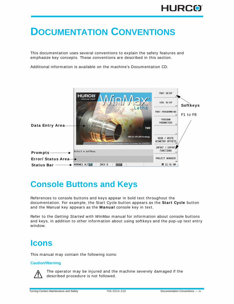
This documentation uses several conventions to explain the safety features and emphasize key concepts. These conventions are described in this section.
Additional information is available on the machine’s Documentation CD.
Console Buttons and Keys
References to console buttons and keys appear in bold text throughout the documentation. For example, the Start Cycle button appears as the Start Cycle button and the Manual key appears as the Manual console key in text.
Refer to the Getting Started with WinMax manual for information about console buttons and keys, in addition to other information about using softkeys and the pop-up text entry window.
IconsThis manual may contain the following icons:
Caution/Warning
The operator may be injured and the machine severely damaged if the described procedure is not followed.
Prompts
Status Bar Error/Status Area
Softkeys
F1 to F8
Data Entry Area
x - Documentation Conventions 704-0214-210 Turning Centers Maintenance and Safety
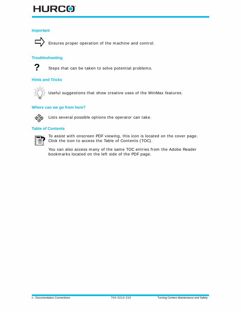
Important
Troubleshooting
Hints and Tricks
Where can we go from here?
Table of Contents
Ensures proper operation of the machine and control.
? Steps that can be taken to solve potential problems.
Useful suggestions that show creative uses of the WinMax features.
Lists several possible options the operator can take.
To assist with onscreen PDF viewing, this icon is located on the cover page. Click the icon to access the Table of Contents (TOC).
You can also access many of the same TOC entries from the Adobe Reader bookmarks located on the left side of the PDF page.
Turning Centers Maintenance and Safety 704-0214-210 Machine Standards 1-1
MACHINE STANDARDS
This chapter describes machine standards for machines sold in Europe (CE). Machine standards for machines sold in the US comply with ANSI standards, also described in this chapter.
CE Requirements
The information in this section ascertains Hurco’s compliance with the European Community’s machine safety standards.
As defined in the Foreword of the “prEN 23125 Safety of Machine Tools—Turning Machines” document, and prEN13788 for Multi-Spindle Automatic Turning Machines (where applicable),“… This European standard has been prepared under a mandate given to CEN by the Commission of the European Communities and the Secretariat of the European Free Trade Association, and supports the essential safety requirements of the Machinery Directive to determine safety for new machining centres.
“This standard has been prepared to provide one means of conforming with the essential requirements of the Machinery Directive and associated EFTA regulations.
“It was prepared by CEN/TC 143 – ‘Machine Tools - Safety’ under the direction of CEN Technical Committee 143 ‘Machine Tools - Safety’…”
European Directives and Standards
Hurco turning centers installed in Europe must conform to the directives and standards accepted by the European community. Consult local authorities for additional safety directives and standards that may apply in your country.
Directives
The Directives are listed on the Declaration of Conformity provided with each machine sold in Europe. Please refer to the sample that follows.
Harmonized Standards
The Standards are listed on the Declaration of Conformity provided with each machine sold in Europe. Please refer to the sample that follows.
Other Standards• BS 5378 Parts 1 & 3
1 - 2 Machine Standards 704-0214-210 Turning Centers Maintenance and Safety
Declaration of Conformity
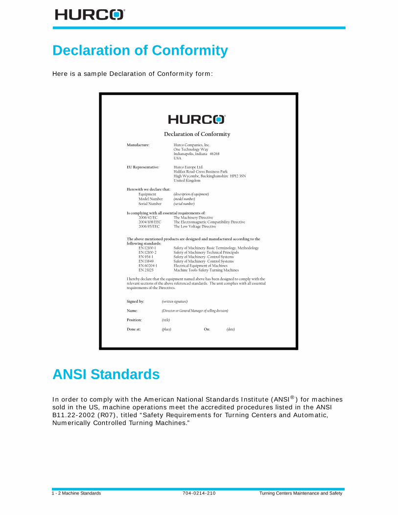
Here is a sample Declaration of Conformity form:
ANSI Standards
In order to comply with the American National Standards Institute (ANSI®) for machines sold in the US, machine operations meet the accredited procedures listed in the ANSI B11.22-2002 (R07), titled “Safety Requirements for Turning Centers and Automatic, Numerically Controlled Turning Machines.”
Declaration of Conformity
Manufacture: Hurco Companies, Inc. One Technology Way Indianapolis, Indiana 46268 USA EU Representative: Hurco Europe Ltd. Halifax Road-Cress Business Park High Wycombe, Buckinghamshire HP12 3SN United Kingdom Herewith we declare that: Equipment (description of equipment) Model Number (model number) Serial Number (serial number) Is complying with all essential requirements of: 2006/42/EC The Machinery Directive 2004/108/EEC The Electromagnetic Compatibility Directive 2006/95/EEC The Low Voltage Directive The above mentioned products are designed and manufactured according to the following standards:
EN 12100-1 Safety of Machinery-Basic Terminology, Methodology EN 12100-2 Safety of Machinery-Technical Principals EN 954-1 Safety of Machinery- Control Systems EN 13849 Safety of Machinery- Control Systems EN 60204-1 Electrical Equipment of Machines EN 23125 Machine Tools-Safety-Turning Machines
I hereby declare that the equipment named above has been designed to comply with the relevant sections of the above referenced standards. The unit complies with all essential requirements of the Directives. Signed by: (written signature) Name: (Director or General Manager of selling division) Position: (title) Done at: (place) On: (date)
Turning Centers Maintenance and Safety 704-0214-210 Machine Components 2-1
MACHINE COMPONENTS
The following topics are covered in this section:
Overview . . . . . . . . . . . . . . . . . . . . . . . . . . . . . . . . . . . . . . . . . . . . . . . . . 2 - 2
Machine Model Names. . . . . . . . . . . . . . . . . . . . . . . . . . . . . . . . . . . . . . . . 2 - 4
Frame . . . . . . . . . . . . . . . . . . . . . . . . . . . . . . . . . . . . . . . . . . . . . . . . . . . 2 - 4
Enclosure . . . . . . . . . . . . . . . . . . . . . . . . . . . . . . . . . . . . . . . . . . . . . . . . 2 - 5
Spindle and Drive System . . . . . . . . . . . . . . . . . . . . . . . . . . . . . . . . . . . . . 2 - 6
Axes Motion System . . . . . . . . . . . . . . . . . . . . . . . . . . . . . . . . . . . . . . . . . 2 - 13
Machine Electrical Cabinet . . . . . . . . . . . . . . . . . . . . . . . . . . . . . . . . . . . . . 2 - 17
Control Systems. . . . . . . . . . . . . . . . . . . . . . . . . . . . . . . . . . . . . . . . . . . . 2 - 26
Operator Control Console . . . . . . . . . . . . . . . . . . . . . . . . . . . . . . . . . . . . . 2 - 26
Coolant System . . . . . . . . . . . . . . . . . . . . . . . . . . . . . . . . . . . . . . . . . . . . 2 - 31
Turret . . . . . . . . . . . . . . . . . . . . . . . . . . . . . . . . . . . . . . . . . . . . . . . . . . . 2 - 33
2 - 2 Machine Components 704-0214-210 Turning Centers Maintenance and Safety
Overview
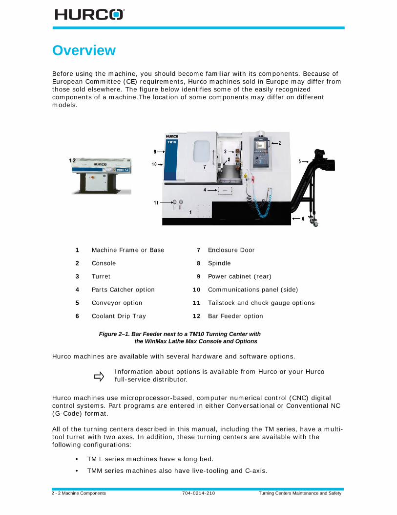
Before using the machine, you should become familiar with its components. Because of European Committee (CE) requirements, Hurco machines sold in Europe may differ from those sold elsewhere. The figure below identifies some of the easily recognized components of a machine.The location of some components may differ on different models.
Figure 2–1. Bar Feeder next to a TM10 Turning Center with the WinMax Lathe Max Console and Options
Hurco machines are available with several hardware and software options.
Hurco machines use microprocessor-based, computer numerical control (CNC) digital control systems. Part programs are entered in either Conversational or Conventional NC (G-Code) format.
All of the turning centers described in this manual, including the TM series, have a multi-tool turret with two axes. In addition, these turning centers are available with the following configurations:
• TM L series machines have a long bed.
• TMM series machines also have live-tooling and C-axis.
1 Machine Frame or Base 7 Enclosure Door
2 Console 8 Spindle
3 Turret 9 Power cabinet (rear)
4 Parts Catcher option 10 Communications panel (side)
5 Conveyor option 11 Tailstock and chuck gauge options
6 Coolant Drip Tray 12 Bar Feeder option
Information about options is available from Hurco or your Hurco full-service distributor.
Turning Centers Maintenance and Safety 704-0214-210 Machine Components 2-3
• TMX series machines have a programmable tailstock.
• TMX MY series machines have live-tooling, Y-axis motion, and a programmable tailstock.
• TMX MYS series machines have live-tooling, Y-axis motion, and a sub-spindle. Options are available to accommodate various turning applications.
Closed loop servo drive systems and motors with rotary encoders power the mechanical drives that position the axes. The rotary encoders provide positioning feedback information to the control. Limit switches mounted on each axis determine end-of-travel and establish reference points for initial machine zeros.
The control positions an axis by sending a command to the appropriate servo drive, which in turn supplies voltage to the axis servomotor.
Refer to the Parts Listing and Wiring Diagrams Manual for mechanical and electrical component drawings for your machine.
Specification measurements are supplied in metric and English.
Machine linear positioning accuracy was set at the factory, in an ambient temperature of 68º F (20º C). Continual operation at higher or lower temperatures may require that you re-compensate the linear positioning accuracy.
Optimum machine performance is reliant upon installation conditions being within Hurco’s recommended specifications (power supply, air supply, ambient air conditions, etc.).
2 - 4 Machine Components 704-0214-210 Turning Centers Maintenance and Safety
Machine Model Names
The TM6, TM8, TM10, TM12, TM18, TM18L, TMM8, TMM10, TMX8, TMX8MY, TMX8MYS, TMX10, TMX10MY, and TMX10MYS machines are described in this manual.
Frame
The major structural assemblies of each machine are constructed of thick-walled, fine-grain cast iron. This construction provides strength and excellent dampening characteristics, keeping deflection and resistance at a minimum during turning.
Head
The cast iron head assembly is designed to produce superior cutting accuracy.
Guideways
The axes guideways are precision linear rails. The tailstock (if equipped) runs on box ways.
Switches and Sensors
Limit switches, proximity switches, and electrical sensors monitor machine functions. These devices report their status to the control. If a malfunction is detected, a stop condition will shut off power to the servo systems and spindle.
Turning Centers Maintenance and Safety 704-0214-210 Machine Components 2-5
Enclosure
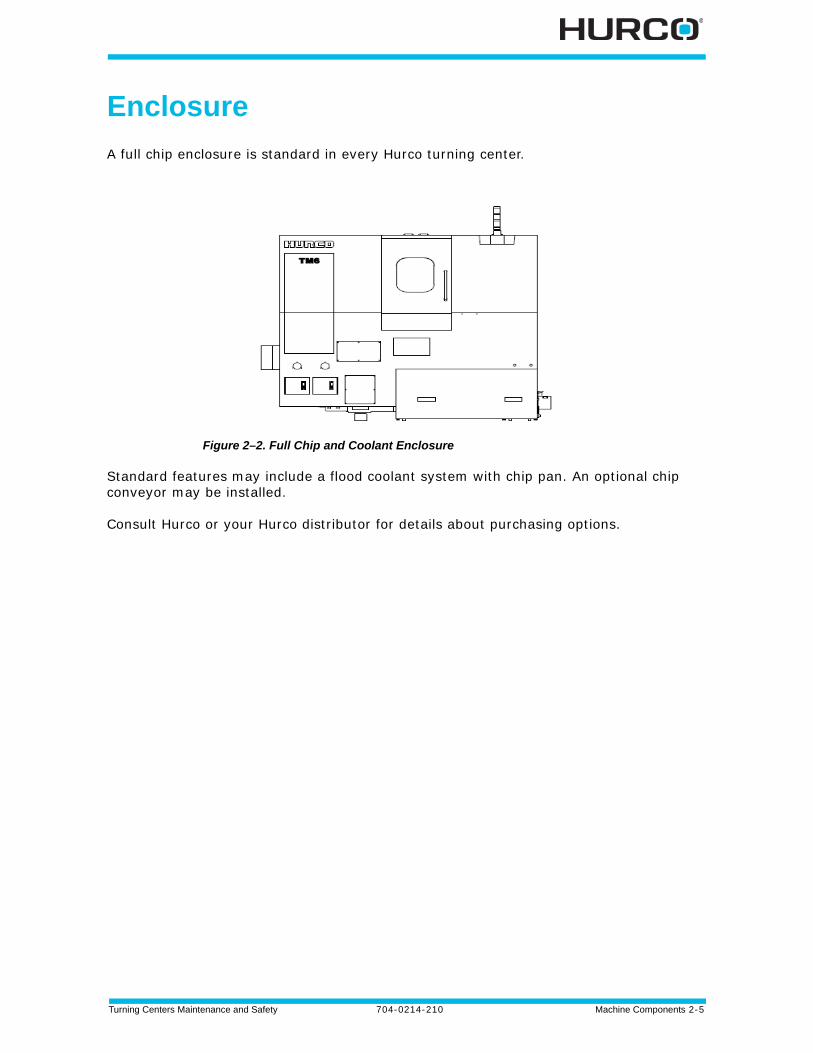
A full chip enclosure is standard in every Hurco turning center.
Figure 2–2. Full Chip and Coolant Enclosure
Standard features may include a flood coolant system with chip pan. An optional chip conveyor may be installed.
Consult Hurco or your Hurco distributor for details about purchasing options.
2 - 6 Machine Components 704-0214-210 Turning Centers Maintenance and Safety
Spindle and Drive System
Hurco machines have a cartridge-type spindle. This spindle is precision-balanced, and made of high-grade alloy steel. The spindle shaft (inside the cartridge) is supported by ABEC-7 class angular contact bearings. The bearings are grease packed.
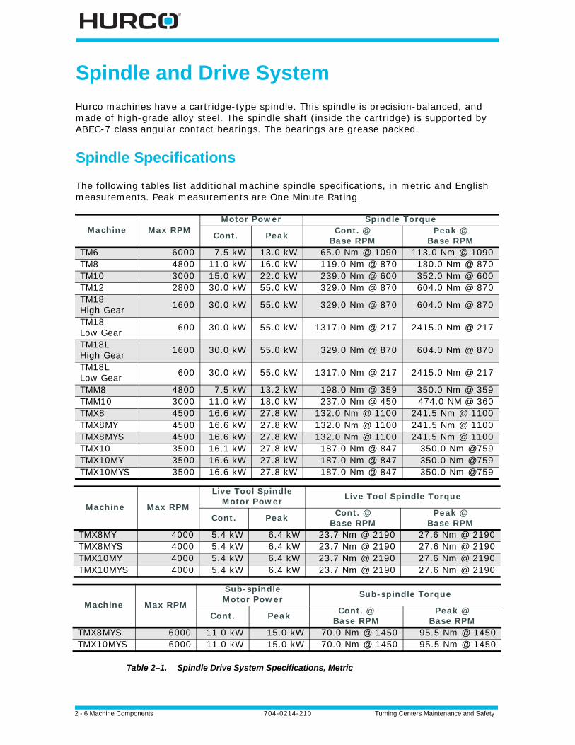
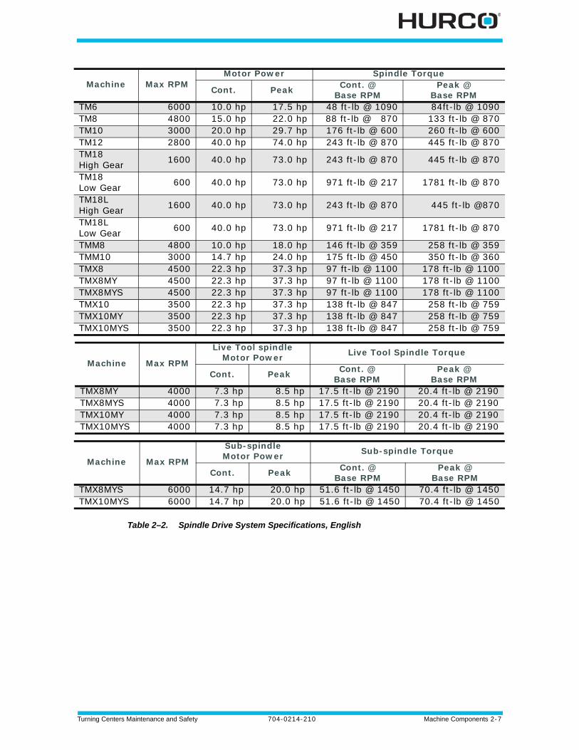
Spindle Specifications
The following tables list additional machine spindle specifications, in metric and English measurements. Peak measurements are One Minute Rating.
Table 2–1. Spindle Drive System Specifications, Metric
Machine Max RPMMotor Power Spindle Torque
Cont. Peak Cont. @ Base RPM
Peak @ Base RPM
TM6 6000 7.5 kW 13.0 kW 65.0 Nm @ 1090 113.0 Nm @ 1090TM8 4800 11.0 kW 16.0 kW 119.0 Nm @ 870 180.0 Nm @ 870TM10 3000 15.0 kW 22.0 kW 239.0 Nm @ 600 352.0 Nm @ 600TM12 2800 30.0 kW 55.0 kW 329.0 Nm @ 870 604.0 Nm @ 870TM18High Gear 1600 30.0 kW 55.0 kW 329.0 Nm @ 870 604.0 Nm @ 870
TM18Low Gear 600 30.0 kW 55.0 kW 1317.0 Nm @ 217 2415.0 Nm @ 217
TM18LHigh Gear 1600 30.0 kW 55.0 kW 329.0 Nm @ 870 604.0 Nm @ 870
TM18LLow Gear 600 30.0 kW 55.0 kW 1317.0 Nm @ 217 2415.0 Nm @ 217
TMM8 4800 7.5 kW 13.2 kW 198.0 Nm @ 359 350.0 Nm @ 359TMM10 3000 11.0 kW 18.0 kW 237.0 Nm @ 450 474.0 NM @ 360TMX8 4500 16.6 kW 27.8 kW 132.0 Nm @ 1100 241.5 Nm @ 1100TMX8MY 4500 16.6 kW 27.8 kW 132.0 Nm @ 1100 241.5 Nm @ 1100TMX8MYS 4500 16.6 kW 27.8 kW 132.0 Nm @ 1100 241.5 Nm @ 1100TMX10 3500 16.1 kW 27.8 kW 187.0 Nm @ 847 350.0 Nm @759TMX10MY 3500 16.6 kW 27.8 kW 187.0 Nm @ 847 350.0 Nm @759TMX10MYS 3500 16.6 kW 27.8 kW 187.0 Nm @ 847 350.0 Nm @759
Machine Max RPM
Live Tool SpindleMotor Power Live Tool Spindle Torque
Cont. Peak Cont. @ Base RPM
Peak @ Base RPM
TMX8MY 4000 5.4 kW 6.4 kW 23.7 Nm @ 2190 27.6 Nm @ 2190TMX8MYS 4000 5.4 kW 6.4 kW 23.7 Nm @ 2190 27.6 Nm @ 2190TMX10MY 4000 5.4 kW 6.4 kW 23.7 Nm @ 2190 27.6 Nm @ 2190TMX10MYS 4000 5.4 kW 6.4 kW 23.7 Nm @ 2190 27.6 Nm @ 2190
Machine Max RPM
Sub-spindleMotor Power Sub-spindle Torque
Cont. Peak Cont. @ Base RPM
Peak @ Base RPM
TMX8MYS 6000 11.0 kW 15.0 kW 70.0 Nm @ 1450 95.5 Nm @ 1450TMX10MYS 6000 11.0 kW 15.0 kW 70.0 Nm @ 1450 95.5 Nm @ 1450
Turning Centers Maintenance and Safety 704-0214-210 Machine Components 2-7
Table 2–2. Spindle Drive System Specifications, English
Machine Max RPMMotor Power Spindle Torque
Cont. Peak Cont. @ Base RPM
Peak @ Base RPM
TM6 6000 10.0 hp 17.5 hp 48 ft-lb @ 1090 84ft-lb @ 1090TM8 4800 15.0 hp 22.0 hp 88 ft-lb @ 870 133 ft-lb @ 870TM10 3000 20.0 hp 29.7 hp 176 ft-lb @ 600 260 ft-lb @ 600TM12 2800 40.0 hp 74.0 hp 243 ft-lb @ 870 445 ft-lb @ 870TM18High Gear 1600 40.0 hp 73.0 hp 243 ft-lb @ 870 445 ft-lb @ 870
TM18Low Gear 600 40.0 hp 73.0 hp 971 ft-lb @ 217 1781 ft-lb @ 870
TM18LHigh Gear 1600 40.0 hp 73.0 hp 243 ft-lb @ 870 445 ft-lb @870
TM18LLow Gear 600 40.0 hp 73.0 hp 971 ft-lb @ 217 1781 ft-lb @ 870
TMM8 4800 10.0 hp 18.0 hp 146 ft-lb @ 359 258 ft-lb @ 359TMM10 3000 14.7 hp 24.0 hp 175 ft-lb @ 450 350 ft-lb @ 360TMX8 4500 22.3 hp 37.3 hp 97 ft-lb @ 1100 178 ft-lb @ 1100TMX8MY 4500 22.3 hp 37.3 hp 97 ft-lb @ 1100 178 ft-lb @ 1100TMX8MYS 4500 22.3 hp 37.3 hp 97 ft-lb @ 1100 178 ft-lb @ 1100TMX10 3500 22.3 hp 37.3 hp 138 ft-lb @ 847 258 ft-lb @ 759TMX10MY 3500 22.3 hp 37.3 hp 138 ft-lb @ 847 258 ft-lb @ 759TMX10MYS 3500 22.3 hp 37.3 hp 138 ft-lb @ 847 258 ft-lb @ 759
Machine Max RPM
Live Tool spindleMotor Power Live Tool Spindle Torque
Cont. Peak Cont. @ Base RPM
Peak @ Base RPM
TMX8MY 4000 7.3 hp 8.5 hp 17.5 ft-lb @ 2190 20.4 ft-lb @ 2190TMX8MYS 4000 7.3 hp 8.5 hp 17.5 ft-lb @ 2190 20.4 ft-lb @ 2190TMX10MY 4000 7.3 hp 8.5 hp 17.5 ft-lb @ 2190 20.4 ft-lb @ 2190TMX10MYS 4000 7.3 hp 8.5 hp 17.5 ft-lb @ 2190 20.4 ft-lb @ 2190
Machine Max RPM
Sub-spindleMotor Power Sub-spindle Torque
Cont. Peak Cont. @ Base RPM
Peak @ Base RPM
TMX8MYS 6000 14.7 hp 20.0 hp 51.6 ft-lb @ 1450 70.4 ft-lb @ 1450TMX10MYS 6000 14.7 hp 20.0 hp 51.6 ft-lb @ 1450 70.4 ft-lb @ 1450
2 - 8 Machine Components 704-0214-210 Turning Centers Maintenance and Safety
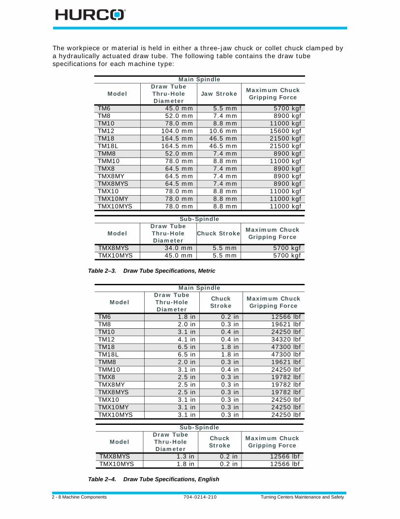
The workpiece or material is held in either a three-jaw chuck or collet chuck clamped by a hydraulically actuated draw tube. The following table contains the draw tube specifications for each machine type:
Table 2–3. Draw Tube Specifications, Metric
Table 2–4. Draw Tube Specifications, English
Main Spindle
ModelDraw Tube Thru-Hole Diameter
Jaw Stroke Maximum Chuck Gripping Force
TM6 45.0 mm 5.5 mm 5700 kgfTM8 52.0 mm 7.4 mm 8900 kgfTM10 78.0 mm 8.8 mm 11000 kgfTM12 104.0 mm 10.6 mm 15600 kgfTM18 164.5 mm 46.5 mm 21500 kgfTM18L 164.5 mm 46.5 mm 21500 kgfTMM8 52.0 mm 7.4 mm 8900 kgfTMM10 78.0 mm 8.8 mm 11000 kgfTMX8 64.5 mm 7.4 mm 8900 kgfTMX8MY 64.5 mm 7.4 mm 8900 kgfTMX8MYS 64.5 mm 7.4 mm 8900 kgfTMX10 78.0 mm 8.8 mm 11000 kgfTMX10MY 78.0 mm 8.8 mm 11000 kgfTMX10MYS 78.0 mm 8.8 mm 11000 kgf
Sub-Spindle
ModelDraw Tube Thru-Hole Diameter
Chuck Stroke Maximum Chuck Gripping Force
TMX8MYS 34.0 mm 5.5 mm 5700 kgfTMX10MYS 45.0 mm 5.5 mm 5700 kgf
Main Spindle
ModelDraw Tube Thru-Hole Diameter
Chuck Stroke
Maximum Chuck Gripping Force
TM6 1.8 in 0.2 in 12566 lbfTM8 2.0 in 0.3 in 19621 lbfTM10 3.1 in 0.4 in 24250 lbfTM12 4.1 in 0.4 in 34320 lbfTM18 6.5 in 1.8 in 47300 lbfTM18L 6.5 in 1.8 in 47300 lbfTMM8 2.0 in 0.3 in 19621 lbfTMM10 3.1 in 0.4 in 24250 lbfTMX8 2.5 in 0.3 in 19782 lbfTMX8MY 2.5 in 0.3 in 19782 lbfTMX8MYS 2.5 in 0.3 in 19782 lbfTMX10 3.1 in 0.3 in 24250 lbfTMX10MY 3.1 in 0.3 in 24250 lbfTMX10MYS 3.1 in 0.3 in 24250 lbf
Sub-Spindle
ModelDraw Tube Thru-Hole Diameter
Chuck Stroke
Maximum Chuck Gripping Force
TMX8MYS 1.3 in 0.2 in 12566 lbfTMX10MYS 1.8 in 0.2 in 12566 lbf

Turning Centers Maintenance and Safety 704-0214-210 Machine Components 2-9
Pressure is adjusted through a valve located behind an access panel at the lower left side of the front of the machine. Clamping by external, internal, or collet type workholding can be set through Manual mode. The chuck is opened or closed by pressing the foot pedal. Refer to the WinMax Lathe Options Help for information about operating the optional collet chuck.
2 - 10 Machine Components 704-0214-210 Turning Centers Maintenance and Safety
AC Spindle Drive Unit
The spindle drive uses Flux Vector method for precise speed and torque control over a wide range of motor speeds. The spindle system also requires an encoder for feedback. A microprocessor along with programming parameters governs the closed-loop control and monitoring.
The following messages are output at terminals via relay contacts:
• Speed Agree
• Spindle Fault
When the spindle drive detects a fault or alarm, the fault information is displayed on the Digital Operator (i.e., OC, or Overcurrent), the fault contact closes, and the motor stops.
Spindle Motor
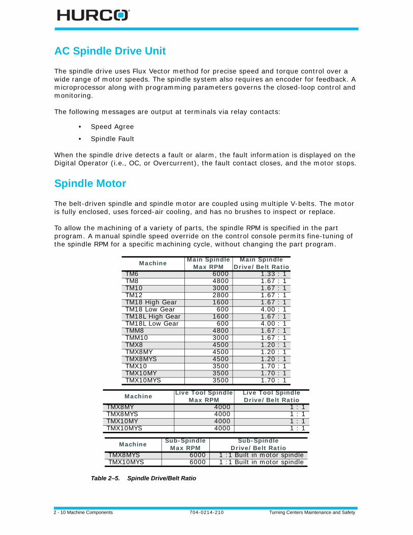
The belt-driven spindle and spindle motor are coupled using multiple V-belts. The motor is fully enclosed, uses forced-air cooling, and has no brushes to inspect or replace.
To allow the machining of a variety of parts, the spindle RPM is specified in the part program. A manual spindle speed override on the control console permits fine-tuning of the spindle RPM for a specific machining cycle, without changing the part program.
Table 2–5. Spindle Drive/Belt Ratio
Machine Main SpindleMax RPM
Main Spindle Drive/Belt Ratio
TM6 6000 1.33 : 1TM8 4800 1.67 : 1TM10 3000 1.67 : 1TM12 2800 1.67 : 1TM18 High Gear 1600 1.67 : 1TM18 Low Gear 600 4.00 : 1TM18L High Gear 1600 1.67 : 1TM18L Low Gear 600 4.00 : 1TMM8 4800 1.67 : 1TMM10 3000 1.67 : 1TMX8 4500 1.20 : 1TMX8MY 4500 1.20 : 1TMX8MYS 4500 1.20 : 1TMX10 3500 1.70 : 1TMX10MY 3500 1.70 : 1TMX10MYS 3500 1.70 : 1
Machine Live Tool SpindleMax RPM
Live Tool Spindle Drive/Belt Ratio
TMX8MY 4000 1 : 1TMX8MYS 4000 1 : 1TMX10MY 4000 1 : 1TMX10MYS 4000 1 : 1
Machine Sub-SpindleMax RPM
Sub-Spindle Drive/Belt Ratio
TMX8MYS 6000 1 :1 Built in motor spindleTMX10MYS 6000 1 :1 Built in motor spindle
Turning Centers Maintenance and Safety 704-0214-210 Machine Components 2-11
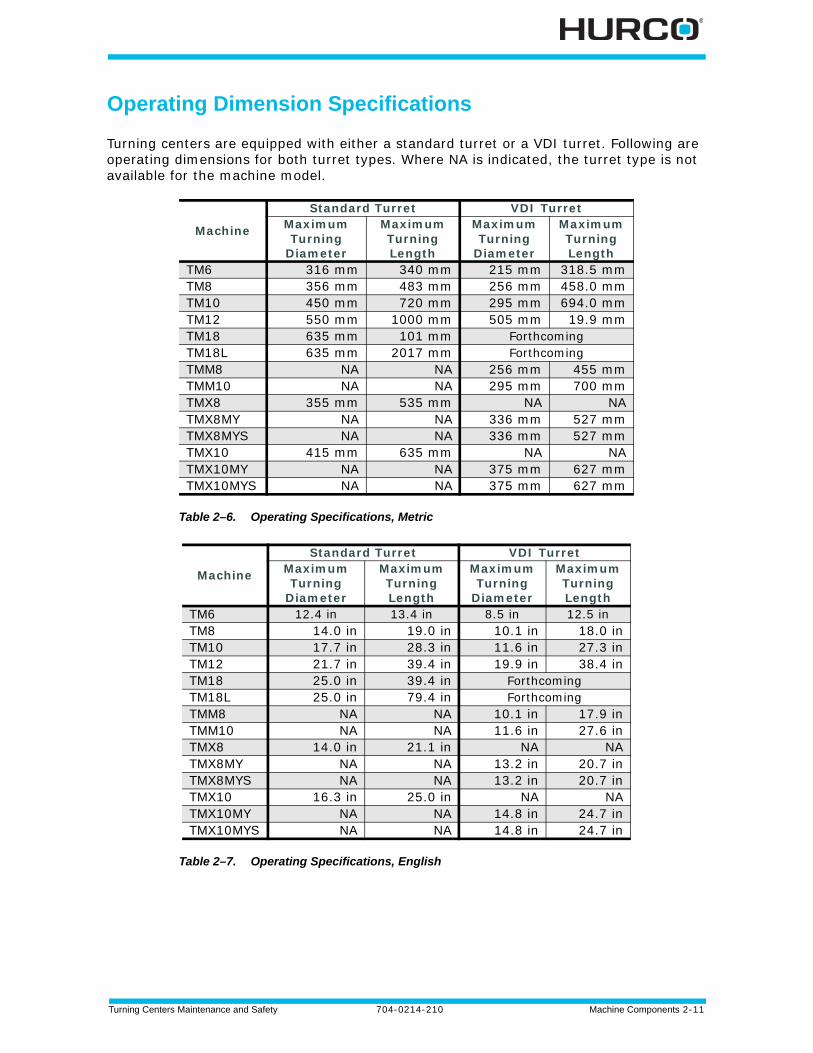
Operating Dimension Specifications
Turning centers are equipped with either a standard turret or a VDI turret. Following are operating dimensions for both turret types. Where NA is indicated, the turret type is not available for the machine model.
Table 2–6. Operating Specifications, Metric
Table 2–7. Operating Specifications, English
Machine
Standard Turret VDI TurretMaximum Turning
Diameter
Maximum Turning Length
Maximum Turning
Diameter
Maximum Turning Length
TM6 316 mm 340 mm 215 mm 318.5 mmTM8 356 mm 483 mm 256 mm 458.0 mmTM10 450 mm 720 mm 295 mm 694.0 mmTM12 550 mm 1000 mm 505 mm 19.9 mmTM18 635 mm 101 mm ForthcomingTM18L 635 mm 2017 mm ForthcomingTMM8 NA NA 256 mm 455 mmTMM10 NA NA 295 mm 700 mmTMX8 355 mm 535 mm NA NATMX8MY NA NA 336 mm 527 mmTMX8MYS NA NA 336 mm 527 mmTMX10 415 mm 635 mm NA NATMX10MY NA NA 375 mm 627 mmTMX10MYS NA NA 375 mm 627 mm
Machine
Standard Turret VDI TurretMaximum Turning
Diameter
Maximum Turning Length
Maximum Turning
Diameter
Maximum Turning Length
TM6 12.4 in 13.4 in 8.5 in 12.5 inTM8 14.0 in 19.0 in 10.1 in 18.0 inTM10 17.7 in 28.3 in 11.6 in 27.3 inTM12 21.7 in 39.4 in 19.9 in 38.4 inTM18 25.0 in 39.4 in ForthcomingTM18L 25.0 in 79.4 in ForthcomingTMM8 NA NA 10.1 in 17.9 inTMM10 NA NA 11.6 in 27.6 inTMX8 14.0 in 21.1 in NA NATMX8MY NA NA 13.2 in 20.7 inTMX8MYS NA NA 13.2 in 20.7 inTMX10 16.3 in 25.0 in NA NATMX10MY NA NA 14.8 in 24.7 inTMX10MYS NA NA 14.8 in 24.7 in
2 - 12 Machine Components 704-0214-210 Turning Centers Maintenance and Safety
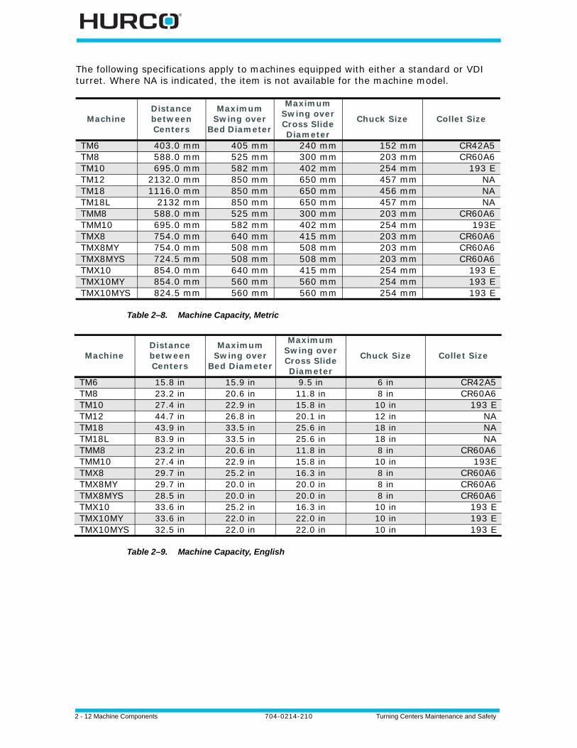
The following specifications apply to machines equipped with either a standard or VDI turret. Where NA is indicated, the item is not available for the machine model.
Table 2–8. Machine Capacity, Metric
Table 2–9. Machine Capacity, English
MachineDistance betweenCenters
Maximum Swing over
Bed Diameter
Maximum Swing over Cross Slide Diameter
Chuck Size Collet Size
TM6 403.0 mm 405 mm 240 mm 152 mm CR42A5TM8 588.0 mm 525 mm 300 mm 203 mm CR60A6TM10 695.0 mm 582 mm 402 mm 254 mm 193 ETM12 2132.0 mm 850 mm 650 mm 457 mm NATM18 1116.0 mm 850 mm 650 mm 456 mm NATM18L 2132 mm 850 mm 650 mm 457 mm NATMM8 588.0 mm 525 mm 300 mm 203 mm CR60A6TMM10 695.0 mm 582 mm 402 mm 254 mm 193ETMX8 754.0 mm 640 mm 415 mm 203 mm CR60A6TMX8MY 754.0 mm 508 mm 508 mm 203 mm CR60A6TMX8MYS 724.5 mm 508 mm 508 mm 203 mm CR60A6TMX10 854.0 mm 640 mm 415 mm 254 mm 193 ETMX10MY 854.0 mm 560 mm 560 mm 254 mm 193 ETMX10MYS 824.5 mm 560 mm 560 mm 254 mm 193 E
MachineDistance betweenCenters
Maximum Swing over
Bed Diameter
Maximum Swing over Cross Slide Diameter
Chuck Size Collet Size
TM6 15.8 in 15.9 in 9.5 in 6 in CR42A5TM8 23.2 in 20.6 in 11.8 in 8 in CR60A6TM10 27.4 in 22.9 in 15.8 in 10 in 193 ETM12 44.7 in 26.8 in 20.1 in 12 in NATM18 43.9 in 33.5 in 25.6 in 18 in NATM18L 83.9 in 33.5 in 25.6 in 18 in NATMM8 23.2 in 20.6 in 11.8 in 8 in CR60A6TMM10 27.4 in 22.9 in 15.8 in 10 in 193ETMX8 29.7 in 25.2 in 16.3 in 8 in CR60A6TMX8MY 29.7 in 20.0 in 20.0 in 8 in CR60A6TMX8MYS 28.5 in 20.0 in 20.0 in 8 in CR60A6TMX10 33.6 in 25.2 in 16.3 in 10 in 193 ETMX10MY 33.6 in 22.0 in 22.0 in 10 in 193 ETMX10MYS 32.5 in 22.0 in 22.0 in 10 in 193 E
Turning Centers Maintenance and Safety 704-0214-210 Machine Components 2-13
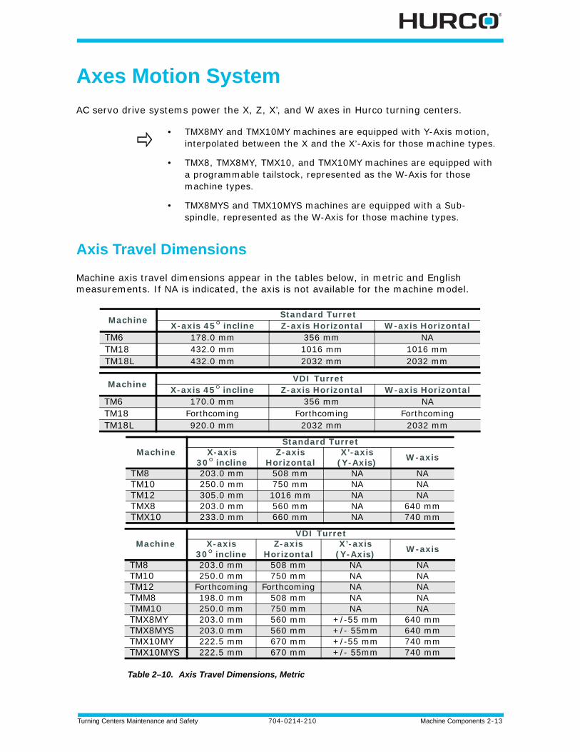
Axes Motion System
AC servo drive systems power the X, Z, X’, and W axes in Hurco turning centers.
Axis Travel Dimensions
Machine axis travel dimensions appear in the tables below, in metric and English measurements. If NA is indicated, the axis is not available for the machine model.
Table 2–10. Axis Travel Dimensions, Metric
• TMX8MY and TMX10MY machines are equipped with Y-Axis motion, interpolated between the X and the X’-Axis for those machine types.
• TMX8, TMX8MY, TMX10, and TMX10MY machines are equipped with a programmable tailstock, represented as the W-Axis for those machine types.
• TMX8MYS and TMX10MYS machines are equipped with a Sub-spindle, represented as the W-Axis for those machine types.
Machine Standard TurretX-axis 45° incline Z-axis Horizontal W-axis Horizontal
TM6 178.0 mm 356 mm NATM18 432.0 mm 1016 mm 1016 mmTM18L 432.0 mm 2032 mm 2032 mm
Machine VDI TurretX-axis 45° incline Z-axis Horizontal W-axis Horizontal
TM6 170.0 mm 356 mm NATM18 Forthcoming Forthcoming ForthcomingTM18L 920.0 mm 2032 mm 2032 mm
MachineStandard Turret
X-axis 30° incline
Z-axis Horizontal
X’-axis (Y-Axis) W-axis
TM8 203.0 mm 508 mm NA NATM10 250.0 mm 750 mm NA NATM12 305.0 mm 1016 mm NA NATMX8 203.0 mm 560 mm NA 640 mmTMX10 233.0 mm 660 mm NA 740 mm
MachineVDI Turret
X-axis 30° incline
Z-axis Horizontal
X’-axis (Y-Axis) W-axis
TM8 203.0 mm 508 mm NA NATM10 250.0 mm 750 mm NA NATM12 Forthcoming Forthcoming NA NATMM8 198.0 mm 508 mm NA NATMM10 250.0 mm 750 mm NA NATMX8MY 203.0 mm 560 mm +/-55 mm 640 mmTMX8MYS 203.0 mm 560 mm +/- 55mm 640 mmTMX10MY 222.5 mm 670 mm +/-55 mm 740 mmTMX10MYS 222.5 mm 670 mm +/- 55mm 740 mm
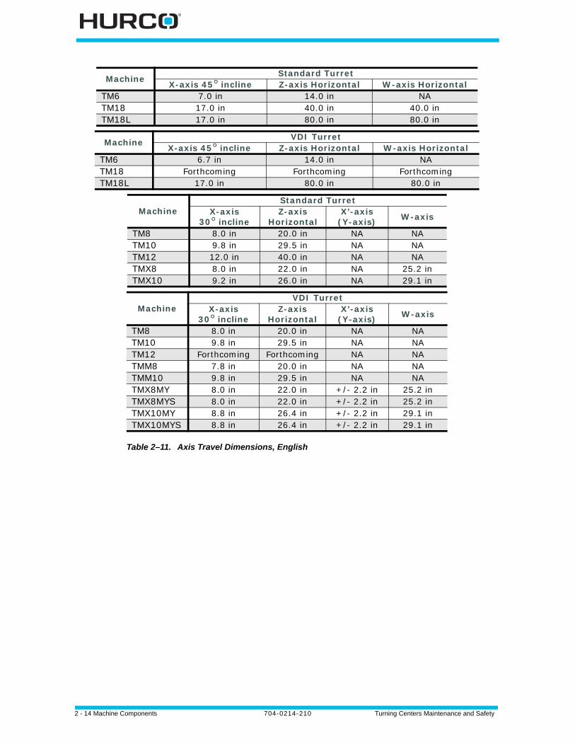
2 - 14 Machine Components 704-0214-210 Turning Centers Maintenance and Safety
Table 2–11. Axis Travel Dimensions, English
Machine Standard TurretX-axis 45° incline Z-axis Horizontal W-axis Horizontal
TM6 7.0 in 14.0 in NATM18 17.0 in 40.0 in 40.0 inTM18L 17.0 in 80.0 in 80.0 in
Machine VDI TurretX-axis 45° incline Z-axis Horizontal W-axis Horizontal
TM6 6.7 in 14.0 in NATM18 Forthcoming Forthcoming ForthcomingTM18L 17.0 in 80.0 in 80.0 in
MachineStandard Turret
X-axis 30° incline
Z-axis Horizontal
X’-axis(Y-axis) W-axis
TM8 8.0 in 20.0 in NA NATM10 9.8 in 29.5 in NA NATM12 12.0 in 40.0 in NA NATMX8 8.0 in 22.0 in NA 25.2 inTMX10 9.2 in 26.0 in NA 29.1 in
MachineVDI Turret
X-axis 30° incline
Z-axis Horizontal
X’-axis(Y-axis) W-axis
TM8 8.0 in 20.0 in NA NATM10 9.8 in 29.5 in NA NATM12 Forthcoming Forthcoming NA NATMM8 7.8 in 20.0 in NA NATMM10 9.8 in 29.5 in NA NATMX8MY 8.0 in 22.0 in +/- 2.2 in 25.2 inTMX8MYS 8.0 in 22.0 in +/- 2.2 in 25.2 inTMX10MY 8.8 in 26.4 in +/- 2.2 in 29.1 inTMX10MYS 8.8 in 26.4 in +/- 2.2 in 29.1 in
Turning Centers Maintenance and Safety 704-0214-210 Machine Components 2-15
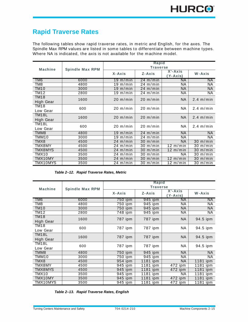
Rapid Traverse Rates
The following tables show rapid traverse rates, in metric and English, for the axes. The Spindle Max RPM values are listed in some tables to differentiate between machine types. Where NA is indicated, the axis is not available for the machine model.
Table 2–12. Rapid Traverse Rates, Metric
Table 2–13. Rapid Traverse Rates, English
Machine Spindle Max RPM
Rapid Traverse
X-Axis Z-Axis X’-Axis(Y-Axis) W-Axis
TM6 6000 19 m/min 24 m/min NA NATM8 4800 19 m/min 24 m/min NA NATM10 3000 19 m/min 24 m/min NA NATM12 2800 19 m/min 24 m/min NA NATM18High Gear 1600 20 m/min 20 m/min NA 2.4 m/min
TM18Low Gear 600 20 m/min 20 m/min NA 2.4 m/min
TM18L High Gear 1600 20 m/min 20 m/min NA 2.4 m/min
TM18LLow Gear 600 20 m/min 20 m/min NA 2.4 m/min
TMM8 4800 19 m/min 24 m/min NA NATMM10 3000 19 m/min 24 m/min NA NATMX8 4500 24 m/min 30 m/min NA 30 m/minTMX8MY 4500 24 m/min 30 m/min 12 m/min 30 m/minTMX8MYS 4500 24 m/min 30 m/min 12 m/min 30 m/minTMX10 3500 24 m/min 30 m/min NA 30 m/minTMX10MY 3500 24 m/min 30 m/min 12 m/min 30 m/minTMX10MYS 3500 24 m/min 30 m/min 12 m/min 30 m/min
Machine Spindle Max RPM
Rapid Traverse
X-Axis Z-Axis X’-Axis(Y-Axis) W-Axis
TM6 6000 750 ipm 945 ipm NA NATM8 4800 750 ipm 945 ipm NA NATM10 3000 750 ipm 945 ipm NA NATM12 2800 748 ipm 945 ipm NA NATM18 High Gear 1600 787 ipm 787 ipm NA 94.5 ipm
TM18Low Gear 600 787 ipm 787 ipm NA 94.5 ipm
TM18LHigh Gear 1600 787 ipm 787 ipm NA 94.5 ipm
TM18LLow Gear 600 787 ipm 787 ipm NA 94.5 ipm
TMM8 4800 750 ipm 945 ipm NA NATMM10 3000 750 ipm 945 ipm NA NATMX8 4500 954 ipm 1181 ipm NA 1181 ipmTMX8MY 4500 945 ipm 1181 ipm 472 ipm 1181 ipmTMX8MYS 4500 945 ipm 1181 ipm 472 ipm 1181 ipmTMX10 3500 945 ipm 1181 ipm NA 1181 ipmTMX10MY 3500 945 ipm 1181 ipm 472 ipm 1181 ipmTMX10MYS 3500 945 ipm 1181 ipm 472 ipm 1181 ipm
2 - 16 Machine Components 704-0214-210 Turning Centers Maintenance and Safety
Servomotors
Axis velocity, position, and travel direction are controlled using AC servomotors along with the CNC control. These motors are enclosed, transistor-driven, and self-cooled. Because they are designed without brushes, the motors are free from flashover and commutation loss.
Ballscrews and Bearings
The precision ballscrews are the double ballnut type . The ballscrews are hardened and ground to minimize “drag torque” and reduce backlash.
The axes positioning drives are supported at the drive-ends by ABEC-7 class bearings.
Feedback Systems
Each drive has circuitry to detect conditions in the servo closed-loop system. Each axis motor is equipped with a rotary encoder that provides velocity and position feedback signals for each closed-loop system. These signals are required for motor control and accurate positioning.
Limit switches mounted on each axis are used to establish reference points for initial machine zeros and for determining end-of-travel.
Turning Centers Maintenance and Safety 704-0214-210 Machine Components 2-17
Machine Electrical Cabinet
The electrical cabinet contains power circuitry and CNC electronics. The cabinet is attached to the machine base and connects to the machine systems via cable and harness assemblies. Power-related circuitry distributes power, while CNC-related electronics control machine operation (e.g., spindle speed and axis positioning).
The electrical control cabinet located at the back of the machine contains CNC-related electronics and power-related circuitry.
Safety Procedures for Electrical Service
Before removing or working on any printed circuit board (PCB), cables, fuses, breakers, or other machine components, make sure that the main disconnect switch on the electrical cabinet door is in the off position. Whenever work will be performed in an area away from the main disconnect switch, post a warning at the switch informing others that the machine is being serviced and the power must remain off.
An industrial UPS (Uninterruptible Power Supply) kit is available as an option. The UPS contains a battery that can power the machine for an extended amount of time in the case of a power outage. Please contact Hurco or your Hurco Distributor for details.
High voltages inside the electrical cabinet can cause serious injury or death. Only qualified personnel may service the machine, and must follow all safety rules and precautions. The line-side of the main disconnect switch is hot, unless the AC source is disconnected.
Service procedures requiring electrical work while equipment is energized shall only be performed by qualified service personnel. Service personnel performing troubleshooting or adjustment procedures to electrical equipment in the control cabinet or other electrical enclosures with doors open or protective covers removed while machine power is energized, shall observe applicable safety practices outlined in NFPA 70E and Occupational Safety and Health Administration (OSHA) 29 CFR part 1910.331-335."
2 - 18 Machine Components 704-0214-210 Turning Centers Maintenance and Safety
Handling Printed Circuit Boards
The following procedures should be taken to prevent damage when removing PCBs, or when checking the boards for proper and secure connections.
Avoid flexing the PCBs. Rough handling can result in hairline cracks in the printed circuit etching. Problems caused by cracks in PC boards can be hard to isolate. Avoid touching the components on a PCB because they can be damaged by static electricity.
• Always put on a static-safe handling wrist strap before touching PCB assemblies inside the cabinets, and before removing replacement boards from their static protective packaging.
• Visually inspect the wrist strap every time you put it on, making sure that the snap fasteners are properly connected.
• Be sure the strap fits snug to the wrist. Taking off the wrist strap should be the last thing done when finished inside the cabinet.
• After the replacement PCB is properly mounted, place the defective PCB assembly into the static shielding and return it to Hurco.
Turning Centers Maintenance and Safety 704-0214-210 Machine Components 2-19
Electrical Cabinet Layout
Electrical cabinet layout may vary depending upon the machine. See the Parts Listing and Wiring Diagrams Manual for your machine model.
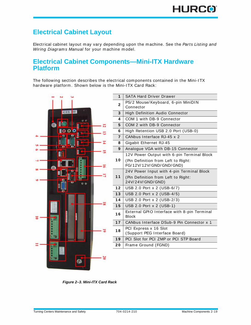
Electrical Cabinet Components—Mini-ITX Hardware Platform
The following section describes the electrical components contained in the Mini-ITX hardware platform. Shown below is the Mini-ITX Card Rack:
Figure 2–3. Mini-ITX Card Rack
1 SATA Hard Driver Drawer
2 PS/2 Mouse/Keyboard, 6-pin MiniDIN Connector
3 High Definition Audio Connector4 COM 1 with DB-9 Connector5 COM 2 with DB-9 Connector6 High Retention USB 2.0 Port (USB-0)7 CANbus Interface RJ-45 x 28 Gigabit Ethernet RJ-459 Analogue VGA with DB-15 Connector
1012V Power Output with 6-pin Terminal Block(Pin Definition from Left to Right: FG/12V/12V/GND/GND/GND)
1124V Power Input with 4-pin Terminal Block(Pin Definition from Left to Right: 24V/24V/GND/GND)
12 USB 2.0 Port x 2 (USB-6/7)13 USB 2.0 Port x 2 (USB-4/5)14 USB 2.0 Port x 2 (USB-2/3)15 USB 2.0 Port x 2 (USB-1)
16 External GPIO Interface with 8-pin Terminal Block
17 CANbus Interface DSub-9 Pin Connector x 1
18 PCI Express x 16 Slot (Support PEG Interface Board)
19 PCI Slot for PCI ZMP or PCI STP Board20 Frame Ground (FGND)

2 - 20 Machine Components 704-0214-210 Turning Centers Maintenance and Safety
Operating Temperature
The electronics inside the electrical cabinet are designed to tolerate ambient temperatures from 0º C (32º F) up to 50º C (122º F). Fans on some of the electronic assemblies and a heat exchanger on the cabinet door circulate warm air away from components. The cabinet contains a temperature sensor mounted on the Slice I/O unit for machines so equipped.
This sensor is preset to a temperature limit of 55º C (131º F). If the temperature exceeds the limit, the machine will post an error message for the operator.
Hurco machines that are not equipped with the air conditioning option may be operated in ambient temperatures to 35º C (95º F), and in relative humidity (non-condensing) up to 95%.
Control Transformer
The 500VA control transformer converts 230VAC to 200W fpr 115 VAC for the CNC power supply and 300W for 115 VAC for the field power supply. The AC outlet on the transformer powers all electrical components.
Power Supply
The Mini-ITX hardware platform uses 2 power supplies: CNC Power and Field Power.
CNC Power
Control power is converted from the 115VAC through a 24VDC, 240W power supply that goes to the terminal block via a cable. Multiple cables exit the terminal block:
• A cable connects from the terminal block into the bottom of the Slice 0 I/O.
• A cable connects from the terminal block to the Mini-ITX Card Rack.
• A cable connects from the terminal block to the RMB (Remote Motion Block).
• A cable connects from the terminal block to the console.
Field Power
Field power is isolated from the control and is converted from the 115VAC through a 24VDC, 120W power supply. The 24VDC runs though the MGND to the Bank Commons located in the Slice I/O and powers sensors and relays.
Turning Centers Maintenance and Safety 704-0214-210 Machine Components 2-21
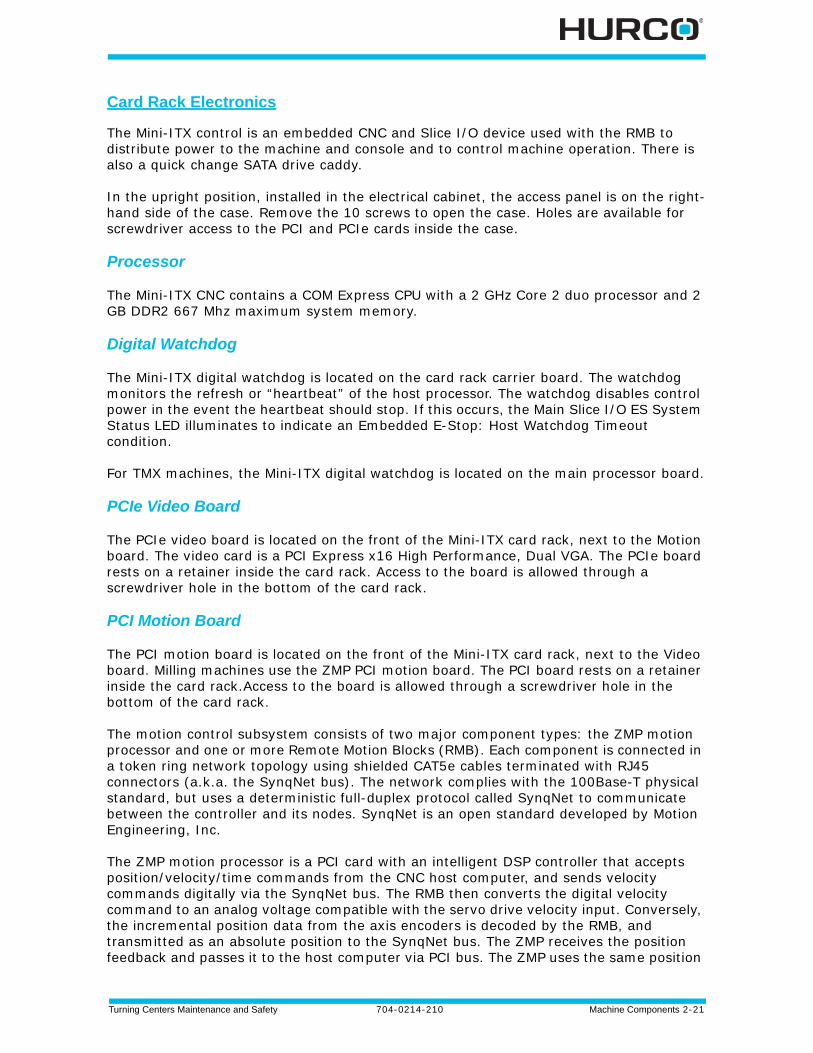
Card Rack Electronics
The Mini-ITX control is an embedded CNC and Slice I/O device used with the RMB to distribute power to the machine and console and to control machine operation. There is also a quick change SATA drive caddy.
In the upright position, installed in the electrical cabinet, the access panel is on the right-hand side of the case. Remove the 10 screws to open the case. Holes are available for screwdriver access to the PCI and PCIe cards inside the case.
Processor
The Mini-ITX CNC contains a COM Express CPU with a 2 GHz Core 2 duo processor and 2 GB DDR2 667 Mhz maximum system memory.
Digital Watchdog
The Mini-ITX digital watchdog is located on the card rack carrier board. The watchdog monitors the refresh or “heartbeat” of the host processor. The watchdog disables control power in the event the heartbeat should stop. If this occurs, the Main Slice I/O ES System Status LED illuminates to indicate an Embedded E-Stop: Host Watchdog Timeout condition.
For TMX machines, the Mini-ITX digital watchdog is located on the main processor board.
PCIe Video Board
The PCIe video board is located on the front of the Mini-ITX card rack, next to the Motion board. The video card is a PCI Express x16 High Performance, Dual VGA. The PCIe board rests on a retainer inside the card rack. Access to the board is allowed through a screwdriver hole in the bottom of the card rack.
PCI Motion Board
The PCI motion board is located on the front of the Mini-ITX card rack, next to the Video board. Milling machines use the ZMP PCI motion board. The PCI board rests on a retainer inside the card rack.Access to the board is allowed through a screwdriver hole in the bottom of the card rack.
The motion control subsystem consists of two major component types: the ZMP motion processor and one or more Remote Motion Blocks (RMB). Each component is connected in a token ring network topology using shielded CAT5e cables terminated with RJ45 connectors (a.k.a. the SynqNet bus). The network complies with the 100Base-T physical standard, but uses a deterministic full-duplex protocol called SynqNet to communicate between the controller and its nodes. SynqNet is an open standard developed by Motion Engineering, Inc.
The ZMP motion processor is a PCI card with an intelligent DSP controller that accepts position/velocity/time commands from the CNC host computer, and sends velocity commands digitally via the SynqNet bus. The RMB then converts the digital velocity command to an analog voltage compatible with the servo drive velocity input. Conversely, the incremental position data from the axis encoders is decoded by the RMB, and transmitted as an absolute position to the SynqNet bus. The ZMP receives the position feedback and passes it to the host computer via PCI bus. The ZMP uses the same position
2 - 22 Machine Components 704-0214-210 Turning Centers Maintenance and Safety
feedback in its fine interpolation algorithm to determine its velocity command.
Each RMB supports four motors (command and feedback) and one encoder (feedback only). Hurco machines use a single RMB for a 3-axis (XYZ and S) configuration. An additional RMB is required for 4th-axis, 5th-axis, and dual loop linear scale configurations.
Servo Transducer, PCI HAL8516H
The PCI motion board is located on the front of the Mini-ITX card rack, next to the Video board. TM and TMM machines use the HAL8516H PCI Servo Transducer motion board. The board rests on a retainer inside the card rack. Access to the board is allowed through a screwdriver hole in the bottom of the card rack.
The motion control subsystem consists of two major component types: the HAL8516H PCI Servo Transducer motion board and one or more Honda-8516H Breakout PCB. Each component is connected in a token ring network topology using shielded CAT5e cables terminated with RJ45 connectors (a.k.a. the SynqNet bus). The network complies with the 100Base-T physical standard, but uses a deterministic full-duplex protocol called SynqNet to communicate between the controller and its nodes. SynqNet is an open standard developed by Motion Engineering, Inc.
The motion processor is a PCI card with an intelligent DSP controller that accepts position/velocity/time commands from the CNC host computer, and sends velocity commands digitally via the SynqNet bus. The Breakout board then converts the digital velocity command to an analog voltage compatible with the servo drive velocity input. Conversely, the incremental position data from the axis encoders is decoded by the Breakout board, and transmitted as an absolute position to the SynqNet bus. The HAL8516H receives the position feedback and passes it to the host computer via PCI bus. The HAL8516H uses the same position feedback in its fine interpolation algorithm to determine its velocity command.
Each Breakout board supports four motors (command and feedback) and one encoder (feedback only). Hurco machines use a single Breakout board for a 3-axis (XYZ and S) configuration. An additional Breakout board is required for 4th-axis, 5th-axis, and dual loop linear scale configurations.
Sercos Card
The PCI motion board is located on the front of the Mini-ITX card rack, next to the Video board. TMX machines use the Sercos NGC motion board. The board rests on a retainer inside the card rack. Access to the board is allowed through a screwdriver hole in the bottom of the card rack.
Turning Centers Maintenance and Safety 704-0214-210 Machine Components 2-23
Slice I/O
The Slice I/O monitors machine sensors and controls electrical and electomechanical devices such as the Tool Changer. The device is mounted on the DIN rail, accommodating installation and servicing. The I/O devices and wiring terminals are merged into one unit for fewer connections, higher reliability, and a smaller footprint.
The standard configuration consists of a Main (Slice 0), a Slave (Slice 1) and another Slave (Slice 2). Each Slice component contains Diagnostic LEDs that indicate the status of all I/O points.
Main Slice
The Main Slice contains System Status LEDs, several Input and Output connections (see Figure 2–4. Slice I/O, on page 2 - 24 for a list of each).
System Status LEDs on Slice 0 indicate the following when lit:
• ES—Embedded E Stop
• RST—System Reset
• OT—Over Temp
• ERR—CAN Communication Error
• TX—CAN Message
Slave Slice
The secondary Slice I/O devices have binary Slice Address LEDs. Each Slice I/O has a unique address. Most machines are equipped with Slice 0 I/O and 2 secondary Slice I/O (Slice 1 and Slice 2), expandable up to 17 slices (268 inputs and 268 outputs) (see Figure 2–4. Slice I/O, on page 2 - 24 for a list of each).
2 - 24 Machine Components 704-0214-210 Turning Centers Maintenance and Safety
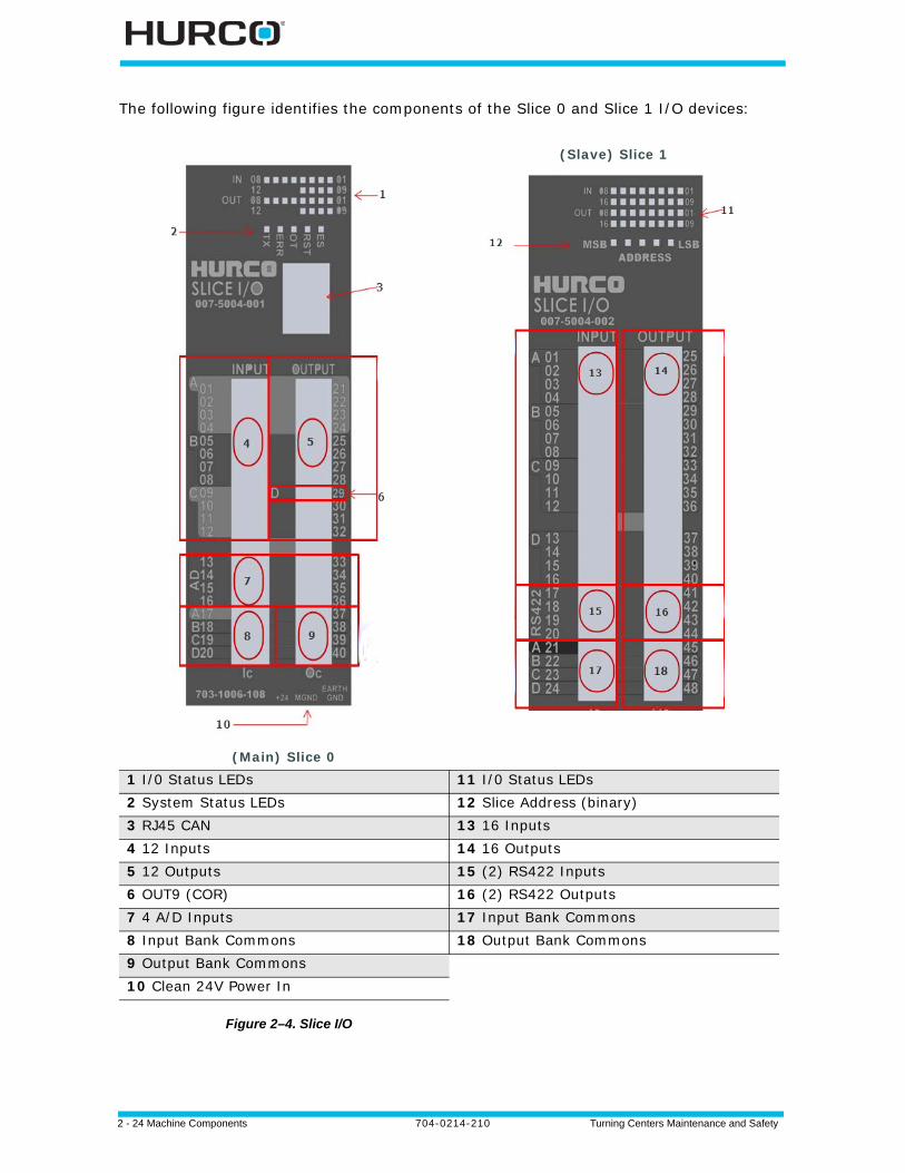
The following figure identifies the components of the Slice 0 and Slice 1 I/O devices:
Figure 2–4. Slice I/O
(Main) Slice 0
(Slave) Slice 1
1 I/0 Status LEDs 11 I/0 Status LEDs2 System Status LEDs 12 Slice Address (binary)3 RJ45 CAN 13 16 Inputs4 12 Inputs 14 16 Outputs5 12 Outputs 15 (2) RS422 Inputs6 OUT9 (COR) 16 (2) RS422 Outputs7 4 A/D Inputs 17 Input Bank Commons8 Input Bank Commons 18 Output Bank Commons9 Output Bank Commons 10 Clean 24V Power In
Turning Centers Maintenance and Safety 704-0214-210 Machine Components 2-25
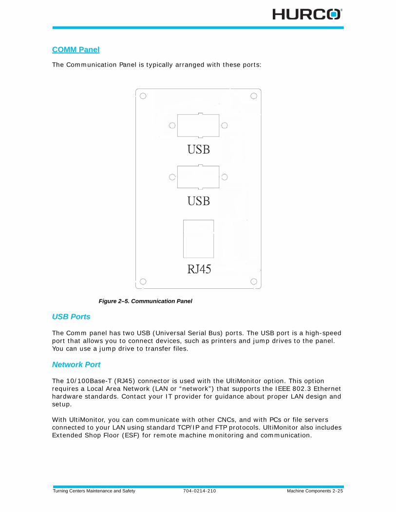
COMM Panel
The Communication Panel is typically arranged with these ports:
Figure 2–5. Communication Panel
USB Ports
The Comm panel has two USB (Universal Serial Bus) ports. The USB port is a high-speed port that allows you to connect devices, such as printers and jump drives to the panel. You can use a jump drive to transfer files.
Network Port
The 10/100Base-T (RJ45) connector is used with the UltiMonitor option. This option requires a Local Area Network (LAN or “network”) that supports the IEEE 802.3 Ethernet hardware standards. Contact your IT provider for guidance about proper LAN design and setup.
With UltiMonitor, you can communicate with other CNCs, and with PCs or file servers connected to your LAN using standard TCP/IP and FTP protocols. UltiMonitor also includes Extended Shop Floor (ESF) for remote machine monitoring and communication.
2 - 26 Machine Components 704-0214-210 Turning Centers Maintenance and Safety
Control Systems
Circuit diagrams for electrical, hydraulic, and pneumatic systems are available in the Parts Listings and Wiring Diagram Manual for the machine.
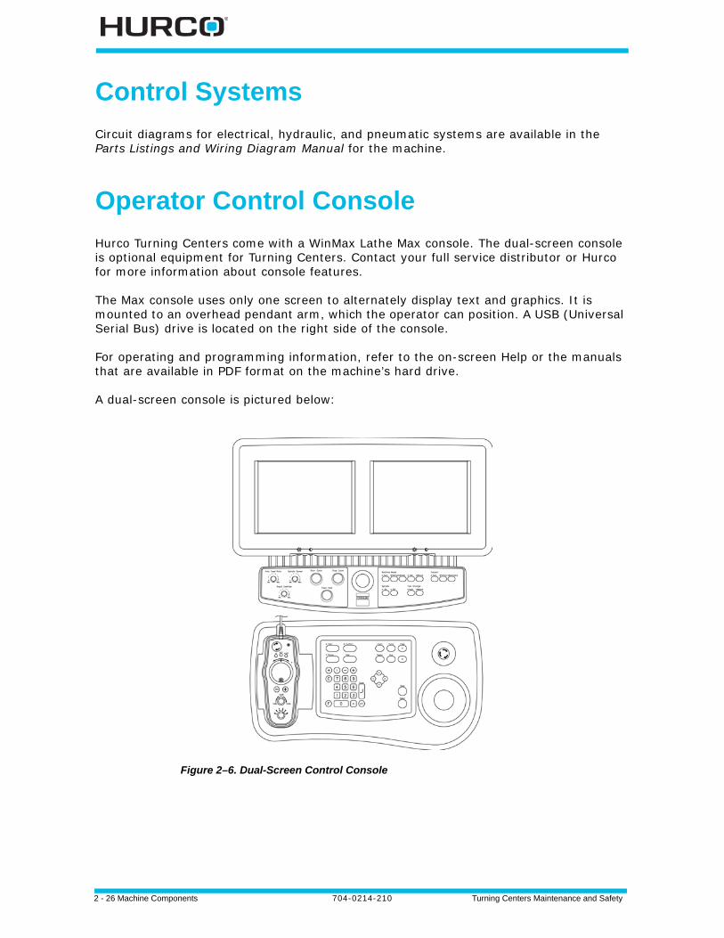
Operator Control Console
Hurco Turning Centers come with a WinMax Lathe Max console. The dual-screen console is optional equipment for Turning Centers. Contact your full service distributor or Hurco for more information about console features.
The Max console uses only one screen to alternately display text and graphics. It is mounted to an overhead pendant arm, which the operator can position. A USB (Universal Serial Bus) drive is located on the right side of the console.
For operating and programming information, refer to the on-screen Help or the manuals that are available in PDF format on the machine’s hard drive.
A dual-screen console is pictured below:
Figure 2–6. Dual-Screen Control Console
Turning Centers Maintenance and Safety 704-0214-210 Machine Components 2-27
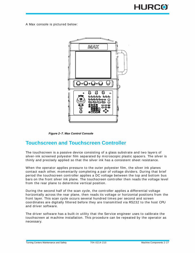
A Max console is pictured below:
Figure 2–7. Max Control Console
Touchscreen and Touchscreen Controller
The touchscreen is a passive device consisting of a glass substrate and two layers of silver-ink screened polyester film separated by microscopic plastic spacers. The silver is thinly and precisely applied so that the silver ink has a consistent sheet resistance.
When the operator applies pressure to the outer polyester film, the silver ink planes contact each other, momentarily completing a pair of voltage dividers. During that brief period the touchscreen controller applies a DC voltage between the top and bottom bus bars on the front silver ink plane. The touchscreen controller then reads the voltage level from the rear plane to determine vertical position.
During the second half of the scan cycle, the controller applies a differential voltage horizontally across the rear plane, then reads its voltage or horizontal positions from the front layer. This scan cycle occurs several hundred times per second and screen coordinates are digitally filtered before they are transmitted via RS232 to the host CPU and driver software.
The driver software has a built-in utility that the Service engineer uses to calibrate the touchscreen at machine installation. This procedure can be repeated by the operator as necessary.

2 - 28 Machine Components 704-0214-210 Turning Centers Maintenance and Safety
Flat Panel Node
The Flat Panel Node (FPN) board communicates console I/O status to the host computer serially via CANbus. The following devices rely on the FPN to function:
• Program Entry Keyboard.
• Machine Function Keyboard.
• Console Keyboard LEDs.
• Control Panel—Pushbuttons, Lamps, Override dials, E-Stop Status.
• Console Jog Functions (Max console only)—Handwheel, Rapid Jog Feed Dial, Axis Selector, +/- Jog console keys, Store Position console key, LEDs.
• Floppy Drive—(if equipped) has a dedicated non-CANbus interface that resides on the FPN. Its SVDC power is sourced from the FPN.
• Remote Jog Unit (FPN provides a CANbus pass-through connection).
Display
The monitor assembly contains a 307.3 mm (12.1 in) LCD TFT module with 800x600 pixel resolution. In addition, a switching power supply and internal A/D board converts the incoming VGA signal to a digital signal compatible with the LCD module. The monitor is powered by DC voltage supplied from the Flat Panel Node. Dual-screen consoles have a brightness control knob under the plastic bezel. Brightness level is fixed on Max console systems.
USB Drive
A USB (Universal Serial Bus) port is located on the right-hand side of the console. It is connected to the main CPU via USB active extension cable in the Control Interface Harness.
Console Jog Unit
Standard Max consoles have a Console Jog Unit. Features include
• Store Position console key
• Manual Pulse Generator (MPG) x1, x10, and x100 rate selections.
• 100 position MPG Handwheel
• Rapid +/- console keys
• Rapid Feed control knob
• Axis selector switch
Turning Centers Maintenance and Safety 704-0214-210 Machine Components 2-29
Remote Jog Unit
Standard dual-screen controls have a Remote Jog Unit that interfaces to the host computer via CANbus. It is powered by 12VDC via the Flat Panel Node. Features include
• Emergency Stop button
• Store Position console key
• Manual Pulse Generator (MPG) x1, x10, and x100 rate selections.
• 100 position MPG Handwheel
• Rapid +/- console keys
• Rapid Feed control knob
• Axis selector switch
The Remote Jog Unit may be equipped with an Enable button.
LCD Remote Jog Unit
The optional LCD Remote Jog Unit features include interfaces to the host computer via CANbus. It is powered by 12VDC via the Flat Panel Node. Features include:
• Motion Hold button
• Stop Cycle button
• Emergency Stop button
• Enable button
• Store Position key
• LCD screen with Mode Selector buttons
• Jog Hand Wheel
• Jog Feed Keys
• Manual Pulse Generator (MPG) x1, x10, and x100 rate selections
• Jog Feed Override
• Axis Select Switch
Please refer to the WinMax Mill Help for details about operating the Remote Jog Unit and the LCD Remote Jog Unit.
2 - 30 Machine Components 704-0214-210 Turning Centers Maintenance and Safety
QWERTY Keyboard Port
A 6-pin mini-DIN female PS2 style keyboard connector is mounted Each connects to the host computer via the Control Interface Harness in the pendant arm (or overarm). An optional external QWERTY keyboard with protective cover and mounting provision is available for each dual-screen and Max control. Information about options is available from Hurco or your Hurco full-service distributor.
If using a QWERTY keyboard, it must be connected prior to powering on the machine.
Turning Centers Maintenance and Safety 704-0214-210 Machine Components 2-31
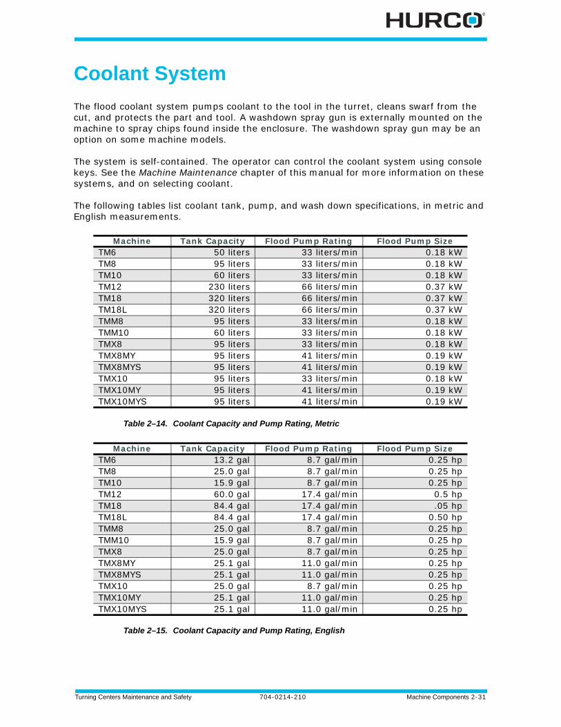
Coolant System
The flood coolant system pumps coolant to the tool in the turret, cleans swarf from the cut, and protects the part and tool. A washdown spray gun is externally mounted on the machine to spray chips found inside the enclosure. The washdown spray gun may be an option on some machine models.
The system is self-contained. The operator can control the coolant system using console keys. See the Machine Maintenance chapter of this manual for more information on these systems, and on selecting coolant.
The following tables list coolant tank, pump, and wash down specifications, in metric and English measurements.
Table 2–14. Coolant Capacity and Pump Rating, Metric
Table 2–15. Coolant Capacity and Pump Rating, English
Machine Tank Capacity Flood Pump Rating Flood Pump SizeTM6 50 liters 33 liters/min 0.18 kWTM8 95 liters 33 liters/min 0.18 kWTM10 60 liters 33 liters/min 0.18 kWTM12 230 liters 66 liters/min 0.37 kWTM18 320 liters 66 liters/min 0.37 kWTM18L 320 liters 66 liters/min 0.37 kWTMM8 95 liters 33 liters/min 0.18 kWTMM10 60 liters 33 liters/min 0.18 kWTMX8 95 liters 33 liters/min 0.18 kWTMX8MY 95 liters 41 liters/min 0.19 kWTMX8MYS 95 liters 41 liters/min 0.19 kWTMX10 95 liters 33 liters/min 0.18 kWTMX10MY 95 liters 41 liters/min 0.19 kWTMX10MYS 95 liters 41 liters/min 0.19 kW
Machine Tank Capacity Flood Pump Rating Flood Pump SizeTM6 13.2 gal 8.7 gal/min 0.25 hpTM8 25.0 gal 8.7 gal/min 0.25 hpTM10 15.9 gal 8.7 gal/min 0.25 hpTM12 60.0 gal 17.4 gal/min 0.5 hpTM18 84.4 gal 17.4 gal/min .05 hpTM18L 84.4 gal 17.4 gal/min 0.50 hpTMM8 25.0 gal 8.7 gal/min 0.25 hpTMM10 15.9 gal 8.7 gal/min 0.25 hpTMX8 25.0 gal 8.7 gal/min 0.25 hpTMX8MY 25.1 gal 11.0 gal/min 0.25 hpTMX8MYS 25.1 gal 11.0 gal/min 0.25 hpTMX10 25.0 gal 8.7 gal/min 0.25 hpTMX10MY 25.1 gal 11.0 gal/min 0.25 hpTMX10MYS 25.1 gal 11.0 gal/min 0.25 hp
2 - 32 Machine Components 704-0214-210 Turning Centers Maintenance and Safety
Pneumatic System
The pneumatic system regulates the air valves that supply compressed air to various machine systems, such as spindle blow out.
The Filter, Regulator, and Lubricator (FRL) Unit is connected to the air manifold, and meters lubricant into the pneumatic system. The FRL prevents moisture from contaminating the compressed air supply, promotes trouble-free operation of air cylinders and valves, and extends the service life of metal components that come in contact with the compressed air stream.
Incoming air pressure can be adjusted using the knob on top of the filter assembly. For information about maintaining the FRL Unit, refer to Filter, Regulator, and Lubricator Unit, on page 4 - 18.
A factory-set air pressure-detecting switch monitors the air supply to the solenoid control valves. Do not tamper with this switch.
Turning Centers Maintenance and Safety 704-0214-210 Machine Components 2-33
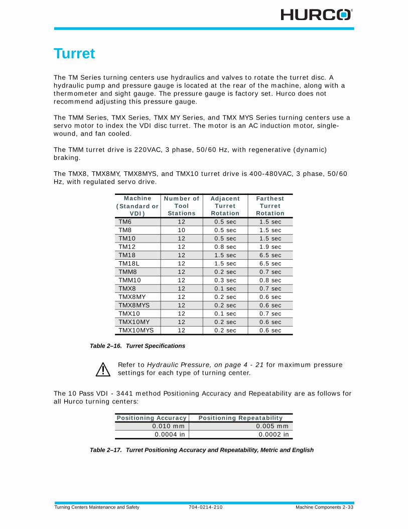
Turret
The TM Series turning centers use hydraulics and valves to rotate the turret disc. A hydraulic pump and pressure gauge is located at the rear of the machine, along with a thermometer and sight gauge. The pressure gauge is factory set. Hurco does not recommend adjusting this pressure gauge.
The TMM Series, TMX Series, TMX MY Series, and TMX MYS Series turning centers use a servo motor to index the VDI disc turret. The motor is an AC induction motor, single-wound, and fan cooled.
The TMM turret drive is 220VAC, 3 phase, 50/60 Hz, with regenerative (dynamic) braking.
The TMX8, TMX8MY, TMX8MYS, and TMX10 turret drive is 400-480VAC, 3 phase, 50/60 Hz, with regulated servo drive.
Table 2–16. Turret Specifications
The 10 Pass VDI - 3441 method Positioning Accuracy and Repeatability are as follows for all Hurco turning centers:
Table 2–17. Turret Positioning Accuracy and Repeatability, Metric and English
Machine(Standard or
VDI)
Number of Tool
Stations
Adjacent Turret
Rotation
Farthest Turret
RotationTM6 12 0.5 sec 1.5 secTM8 10 0.5 sec 1.5 secTM10 12 0.5 sec 1.5 secTM12 12 0.8 sec 1.9 secTM18 12 1.5 sec 6.5 secTM18L 12 1.5 sec 6.5 secTMM8 12 0.2 sec 0.7 secTMM10 12 0.3 sec 0.8 secTMX8 12 0.1 sec 0.7 secTMX8MY 12 0.2 sec 0.6 secTMX8MYS 12 0.2 sec 0.6 secTMX10 12 0.1 sec 0.7 secTMX10MY 12 0.2 sec 0.6 secTMX10MYS 12 0.2 sec 0.6 sec
Refer to Hydraulic Pressure, on page 4 - 21 for maximum pressure settings for each type of turning center.
Positioning Accuracy Positioning Repeatability 0.010 mm 0.005 mm0.0004 in 0.0002 in
2 - 34 Machine Components 704-0214-210 Turning Centers Maintenance and Safety
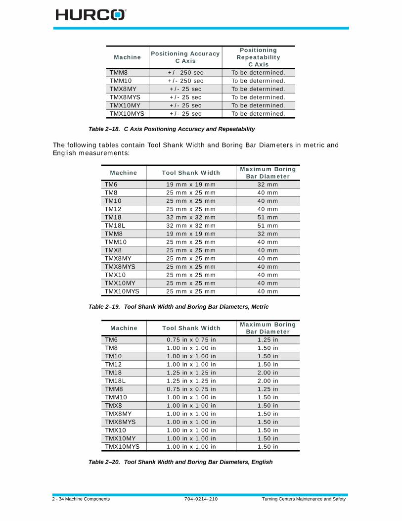
Table 2–18. C Axis Positioning Accuracy and Repeatability
The following tables contain Tool Shank Width and Boring Bar Diameters in metric and English measurements:
Table 2–19. Tool Shank Width and Boring Bar Diameters, Metric
Table 2–20. Tool Shank Width and Boring Bar Diameters, English
Machine Positioning Accuracy C Axis
Positioning Repeatability
C AxisTMM8 +/- 250 sec To be determined.TMM10 +/- 250 sec To be determined.TMX8MY +/- 25 sec To be determined.TMX8MYS +/- 25 sec To be determined.TMX10MY +/- 25 sec To be determined.TMX10MYS +/- 25 sec To be determined.
Machine Tool Shank Width Maximum Boring Bar Diameter
TM6 19 mm x 19 mm 32 mmTM8 25 mm x 25 mm 40 mmTM10 25 mm x 25 mm 40 mmTM12 25 mm x 25 mm 40 mmTM18 32 mm x 32 mm 51 mmTM18L 32 mm x 32 mm 51 mmTMM8 19 mm x 19 mm 32 mmTMM10 25 mm x 25 mm 40 mmTMX8 25 mm x 25 mm 40 mmTMX8MY 25 mm x 25 mm 40 mmTMX8MYS 25 mm x 25 mm 40 mmTMX10 25 mm x 25 mm 40 mmTMX10MY 25 mm x 25 mm 40 mmTMX10MYS 25 mm x 25 mm 40 mm
Machine Tool Shank Width Maximum Boring Bar Diameter
TM6 0.75 in x 0.75 in 1.25 inTM8 1.00 in x 1.00 in 1.50 inTM10 1.00 in x 1.00 in 1.50 inTM12 1.00 in x 1.00 in 1.50 inTM18 1.25 in x 1.25 in 2.00 inTM18L 1.25 in x 1.25 in 2.00 inTMM8 0.75 in x 0.75 in 1.25 inTMM10 1.00 in x 1.00 in 1.50 inTMX8 1.00 in x 1.00 in 1.50 inTMX8MY 1.00 in x 1.00 in 1.50 inTMX8MYS 1.00 in x 1.00 in 1.50 inTMX10 1.00 in x 1.00 in 1.50 inTMX10MY 1.00 in x 1.00 in 1.50 inTMX10MYS 1.00 in x 1.00 in 1.50 in
Turning Centers Maintenance and Safety 704-0214-210 Machine Components 2-35
Turret Operation
When moving the turret to perform Turret Diagnostics, to set the Active Tool using the Manual screen’s softkey menu, or the turret +/- console keys, the turret operates as follows:
1. The turret unclamps.
2. The turret rotates and increments or decrements one position.
3. The turret clamps.
Keep tool clearances in mind during tool setup to avoid tools coming in contact with the chuck or way covers.
The Start Cycle button flashes when the Turret -/+ console key is pressed. Press the flashing button to manually move the turret.

2 - 36 Machine Components 704-0214-210 Turning Centers Maintenance and Safety
Turning Centers Maintenance and Safety 704-0214-210 Operation Requirements 3-1
OPERATION REQUIREMENTS
This chapter contains the following requirements for operating the turning center.
Machine Installation . . . . . . . . . . . . . . . . . . . . . . . . . . . . . . . . . . . . . . . . . 3 - 2
Initial Test and Examination. . . . . . . . . . . . . . . . . . . . . . . . . . . . . . . . . . . . 3 - 5
Proper Operation and Maintenance . . . . . . . . . . . . . . . . . . . . . . . . . . . . . . . 3 - 6
Machinery Safety . . . . . . . . . . . . . . . . . . . . . . . . . . . . . . . . . . . . . . . . . . . 3 - 10
Noise Levels. . . . . . . . . . . . . . . . . . . . . . . . . . . . . . . . . . . . . . . . . . . . . . . 3 - 15
3 - 2 Operation Requirements 704-0214-210 Turning Centers Maintenance and Safety
Machine Installation
Inspect the machine to ensure that all parts are included and intact. The owner is responsible for proper site preparation before the machine is installed. A Hurco Field Service Engineer must install the machine in the prepared location. This location must not subject the machine to uncontrolled cabinet temperatures or unfavorable work environment conditions that could cause electronic component failure.
If the owner decides later to move the machine from its installed location, it is recommended that the owner call Hurco for assistance.
Guarding System
Each machine has a self-contained guarding system. Enclosure doors are located on the front of each machine. Inspect the machine to ensure the guarding system is intact.
• The enclosure doors lock during Automatic Run Mode to prevent access to the moving parts of the machine.
• The side doors on each machine are either latched or secure.
• The enclosure doors are secured with an interlocking door switch.
Foundation Conditions
The foundation must be able to support the weight of the machine, and should be constructed of continuous concrete (reinforced concrete is best). The thickness and consistency of the concrete must be compatible with industry standards for supporting machine weight. Actual requirements will depend upon the physical properties of underlying soil. Friction pads or machine anchors may be required to assure optimal machine performance.
Improper moving of the machine may result in personal injury or damage to the machine.
Turning Centers Maintenance and Safety 704-0214-210 Operation Requirements 3-3
Electrical Service Requirements
Follow all requirements below to help ensure personnel safety and to prevent equipment damage.
Run electrical power to the machine location, with adequate length to reach the connections in the power cabinet. Final connections MUST be supervised by a Hurco-certified Service Engineer.
Connecting Electrical Service
Observe the following guidelines when connecting electrical service:
• On-site wiring must comply with all established directives and standards.
• Dedicated, grounded 3-phase AC power is required to prevent high and/or low voltages, spikes, surges, and high frequency noise caused by inductive loads.
• The AC power source must match the voltage specifications listed on the machine data plate.
• Failure to provide the required power parameters may affect machine safety, performance and warranty.
• Wiring to the machine must be capable of supplying continuous, full-load specified amperage.
Recommended Isolation Transformer Configuration
If a transformer other than the one provided with the machine is used, it must meet Hurco’s machine operating voltage requirements. Use a Delta to balanced Wye configuration. Refer to the Getting Started manual for more information.
Grounding Equipment
The machine electrical and electronic control systems are interconnected, terminating at the Protective Earth (PE) or ground point.
• The ground point must be properly connected to the ground circuit of the AC power source. The ground point is located inside of the machine’s power cabinet.
• The ground point provides only one conducting path between the machine and external ground, preventing an unwanted ground loop (ground differential voltage).
3 - 4 Operation Requirements 704-0214-210 Turning Centers Maintenance and Safety
Compressed Air Requirements
For machines requiring compressed air, a continuous supply of clean and dry air is essential for proper machine operation, and must be connected to the machine as described here.
Compressed Air Specification
Compressed air must conform to the specification:
• 5 CFM at 80 - 100 psi; or
• 0.14 M3/min at 6.0 - 8.0 bar.
• Air humidity: 2º C (35º F)
Connecting Compressed Air
The air supply line must meet these requirements:
• An NPT pipefitting must connect the air supply line to the machine.
• A regulator valve must be installed to control the air pressure into the machine.
• A factory-set pressure switch must be installed to shut off control voltages if the air pressure falls below the pre-set level.
• A minimum 1.27 cm diameter (1/2 inch, trade size) pipe, or an equivalent 1.99 cm (7/8 inch) diameter air hose supply line is required to provide adequate air volume.
• A drip leg should be installed in the line ahead of the filter/regulator assembly. The drip leg will help remove moisture accumulation in the supply, making the filter last longer.
• Quick coupler type fittings should not be used at the connection to the air filter/regulator, or within the supply line to the machine.
Anti-Vibration Mountings
Anti-vibration mountings, consisting of a spring-mounted ball bearing, are attached to each machine. Loose springs and balls are signs of excessive vibration.
Check the mountings before uncrating the machine to ensure that the machine has been handled properly prior to its arrival. Continue to inspect the mountings on a regular basis.
Turning Centers Maintenance and Safety 704-0214-210 Operation Requirements 3-5
Initial Test and Examination
Follow the instructions below for performing the initial test and examination of the machine and its guarding system.
Arrange for a Hurco-certified Service Engineer to perform the final machine setup. Complete these procedures prior to the arrival of the Service Engineer:
1. Provide utilities to the machine.
2. Check all machine lubrication levels.
3. Place the flood coolant tank, tubing, and coolant pump motor near the machine base.
The Hurco-certified Service Engineer performs these tasks:
1. Inspects the machine level and makes required adjustments.
2. Checks and connects electrical service to the machine.
3. Installs the control console.
4. Measures voltages in the electrical cabinet and control enclosure and makes adjustments, if needed.
5. Installs the flood coolant tank, tubing, and coolant pump motor.
6. Installs covers and enclosures.
7. Checks fans and pumps for proper operation.
8. Checks all axes for calibration and correct limit switch operation.
9. Tests the disk drive.
Hurco is not responsible for failures of the motor encoder and cable assemblies resulting from abuse and direct spray of coolant.
3 - 6 Operation Requirements 704-0214-210 Turning Centers Maintenance and Safety
Proper Operation and Maintenance
This section addresses the proper operation of the machine. The information presented here is not a substitute for operator training, skill, and good judgment. Hurco does not accept any liability for operator error.
Training for Operators
Hurco or a Hurco-authorized distributor must train all machine operators. Hurco offers classes to demonstrate the programming capabilities of its CNC system. The training classes provide hands-on development of part programs.
Study this manual before attempting to operate the machine and become familiar with machine functions and safety features. Review all caution and warning messages, as well as all warning and instruction plates or decals on the machine.
Enclosure Doors and Guarding
Hurco machines are built to comply with the standards outlined in the Machine Standards chapter. Enclosure doors are located on the front of each machine.
Enclosure doors are provided to minimize the risks of ejection of the workpiece, machine components, tools or parts of them, swarf, chips, or coolant.
Enclosure doors are designed and constructed to withstand foreseeable impact energy, depending upon the diameter of the largest possible clamping device for the machine and its maximum speed.
If machining unbalanced workpieces, an ejection hazard is possible. Reduce this risk by counter balancing or machining at reduced speeds. Enclosure doors are intended to minimize the risks of ejection and not to eliminate them completely.
Enclosure doors should always be closed when the machine is operating in Auto Mode.
Turning Centers Maintenance and Safety 704-0214-210 Operation Requirements 3-7
Setup
Follow these precautions during machine and production setup:
• Perform all setup work with the Emergency Stop engaged. Never put your hands near a part being machined.
• Clamp the fixtures and workpiece securely before starting the machine. Loose objects such as wrenches and chuck keys can become flying projectiles if not removed before starting the machine.
• Wear gloves or use a shop cloth when handling tooling.
• Inspect tools and tool holders frequently. Use tools that are properly sharpened and in good condition.
• Never start the machine when the cutter is in contact with the workpiece. Make sure the direction of spindle rotation is correct to prevent cutter breakage. Rotate the spindle clockwise for right-hand tools, and counterclockwise for left-hand tools.
• Keep the work area well-lighted. Adjust lamps so that light does not shine directly into the operator’s eyes.
• Make certain all guards are in place before beginning operation.
Operation and Maintenance
• Know where the Emergency Stop pushbuttons are located.
• The operator should stay within reach of an Emergency Stop button when the machine is in motion.
• Be aware of all pinch points caused by the motion of the axes and turret. Be aware of protruding machine parts.
• Keep the electrical cabinet doors closed while power is on. Before opening the electrical cabinet doors, verify that the main disconnect switch has been turned Off.
• Do not remove or bypass safety limit switches, interlocks, and other safeguards.
• Do not start the machine unless all systems contain the proper amount and type of lubricant.
• Make certain that all necessary guards and protective devices are in place before operating the machine.
• If unusual sounds, smoke, heat or damaged parts occur, turn off the machine.
High voltages present in the machine electrical system can cause serious injury or death.
3 - 8 Operation Requirements 704-0214-210 Turning Centers Maintenance and Safety
Working Practices
Follow the correct service and repair procedures to ensure proper operation of the machine, and to reduce the likelihood of serious operator injury.
Observe these basic precautions when working near a machine:
Responsible Conduct
• Follow the instructions provided when performing a maintenance task.
• Keep all parts of your body away from moving parts.
• Be alert and keep safety in mind.
• Never attempt to operate or repair a machine if you have taken strong medication, used a prescription drug, or consumed an alcoholic beverage.
• Do not attempt to operate or repair a machine until you have read and understood all information that pertains to the machine, including all warning and instruction plates or decals mounted on the machine.
• Know how the machine functions, and understand its safety features.
Personal Care
• Avoid frequent or prolonged skin contact with fresh or used cutting fluids and oils.
• If machining chemicals come in contact with your skin, wash the area immediately.
• Wash your hands thoroughly before eating.
• Change clothing that has become contaminated with machining fluids and oils.
• For complete information about handling industrial chemicals used in machining, refer to the international Control of Substances Hazardous to Health (COSHH) materials from the chemical suppliers.
Wearing Apparel
• Wear eye protection and safety shoes while in the machining work area. Safety glasses with side shields are recommended. Safety shoes should be in good condition, with steel reinforced toes and oil-resistant soles.
• Remove clothing and jewelry that could get caught in machine moving parts. Do not wear loose-fitting clothing. Long shirt sleeves are not recommended.
• Keep long hair tied back so that vision is not obstructed and hair cannot become caught in moving parts.
Turning Centers Maintenance and Safety 704-0214-210 Operation Requirements 3-9
Heavy Lifting
• Do not attempt to lift more than you can safely handle. When lifting, keep your back straight and use your legs.
• Use a hoist for heavy lifting, making sure that the load is evenly balanced and is raised slowly.
• Do not raise a large load over aisles and make certain that the landing area is clear and level.
Housekeeping
• Maintain a clean and orderly workspace around the machine. The floor must be free of spills and obstructions.
• Use only sturdy work platforms with anti-slip surfaces around the machine.
• Do not store tools, shop cloths, and miscellaneous parts on the machine.
• When removing chips, make certain the spindle is completely stopped. Use a brush or chip scraper to remove chips—do not use compressed air to blow chips from the spindle, controls, cabinet or floor. Do not remove chips by hand, or while the spindle is turning. Dispose of chips frequently.
3 - 10 Operation Requirements 704-0214-210 Turning Centers Maintenance and Safety
Machinery Safety
The Hurco machine’s safety circuit is designed to provide safe and reliable operation. Tamper-resistant fasteners are used to hold combination door lock/switches in place and to prevent access to internal wiring.
If the owner or operator modifies the hardware or software by removing, altering, disabling, or tampering with any safety circuit, safety switch, or other safety operation and operates the machine with those modifications, such operation is extremely hazardous and is a foreseeable misuse of the machine, and voids the Hurco warranty. In addition, it may be in violation of federal or local regulations, directives, codes, or ordinances. If such modifications are discovered, the machine must be immediately shut off and not used. Contact a Hurco-certified Service Engineer for assistance in restoring the machine to safe operation.
Following are basic rules governing operation. Please refer to Operation Requirements, on page 3 - 11 for details about operation limitations with doors open.
• The spindle cannot operate unless all enclosure doors are closed, excluding doors that are fastened shut with bolts or screws.
• When the Limited Manual Operations are Enabled in the CE Diagnostics screen, the spindle can be run and the axes can be jogged with the enclosure door open at a limited RPM when the Start Cycle button and the Enable button are pressed and held down.
• Enclosure doors must be closed and locked during automatic operation, such as run program, warm-up cycle, calibration cycle, turret diagnostics functions, or tool setter.
• In the event that an enclosure door is opened during automatic operation, an immediate command to stop all motion will be executed, changing modes from Auto to Interrupt.
• Redundancy is included in electrical design to detect single point failures (e.g., switch contact, relay coil).
• After turning off control power, and after a deceleration delay of approximately 7 to 10 seconds, the spindle drive will be disabled.
• When the Emergency Stop button is pressed, power is removed from the spindle and axis drives, and the door locking mechanism is enabled.
Pressing the Emergency Stop button will lock the enclosure doors.
Turning Centers Maintenance and Safety 704-0214-210 Operation Requirements 3-11
Operation Requirements
Hurco machine tools are equipped with door interlocks to ensure the enclosure doors do not open during machining operations. Periodically check the safety circuits, especially after changing components. Basic mode operations are listed below.
An Enable, or Common, button is located on the side of the Max console. In order to perform specific operations with the enclosure doors open, both the Enable button and the Start Cycle button must be pressed.
The Enable button has three positions: fully up (off), middle (on), and fully down (off). The button must be in the middle position to be enabled.
Manual Mode Operations, Enclosure Doors Open• Cannot turn Control Power On unless Enclosure and Spindle doors are closed
(for TMX machines only).
• Cannot park the machine or home the axes.
• Cannot begin machine calibration cycle.
• Cannot start conveyor.
• Cannot perform coolant functions except for washdown gun.
• Cannot perform these Turret Diagnostic functions: Reference Turret and Orient Spindle. (Not available for TM Series machines.)
• Cannot retract the Part Catcher (if equipped).
• Cannot perform Tool Probing (if equipped) where the Live Spindle (if equipped) is required to run.
• Cannot run the Steady Rest Clamp/Unclamp (if equipped).
• Cannot run a part program in Auto mode.
Pressing the Emergency Stop button will lock the enclosure doors.
Chuck and Tailstock (if equipped) operations are always possible when the doors are open and the machine is powered On in any mode.
The Auto Door option (if equipped) requires pressing the Enable and Start Cycle buttons at the same time. The Auto Door is operational when the machine is powered On.
You may access the Auto (Conversational) screen and select the Run Part Program F8 softkey. The Start Cycle button flashes. When you press Start Cycle at this point, a message appears: “Cannot Start Cycle with Guard Door open.” Press the OK screen button to continue. At this point, you can shut the door and press Start Cycle to run the program.
You may select the Auto console key and access Auto (Conversational) screen to perform Estimated Run Time or Check for Errors regardless of door status.
3 - 12 Operation Requirements 704-0214-210 Turning Centers Maintenance and Safety
Manual Mode Operations, Spindle Door Open
The Spindle Door is located on the machine’s Left Side (facing machine),
• Cannot turn Control Power On unless Enclosure and Left Side doors are closed (for TMX machines only).
• Cannot begin machine calibration cycle.
• Cannot activate Spindle 1 On.
• Cannot run C-axis (TMM and TMX Series).
• Cannot perform Turret Diagnostics, including Reference Turret and Orient Spindle. (Not available for TM Series machines.)
Limited Manual Operations Enabled, Enclosure Doors Open
The user may enable limited manual operations with the doors open to allow the spindle to run at a limited speed, jog the axes at a limited feedrate, or index the turret. Refer to Enabling Limited Manual Operations, on page 3 - 13 for directions. When Limited Manual Operations are Enabled in the CE Diagnostics screen,
• Cannot run spindle unless the Enable button is pressed and held down at the same time with the Start Cycle button. The spindle will turn off if the Enable button is released.
• Spindle speed is limited to 50 RPM, including setting on Spindle Speed override dial.
• Spindle speed is limited so it will stop within 2 revolutions, including setting on Spindle Speed override dial.
• Can jog the axes using the “+” or “-” jog keys. The axes feedrate is limited to 2M/min (78.7 in/min), or as otherwise specified by regulations, including the setting of Axis Feed Rate override dial.
• If the Enable button is equipped, you must press and hold both the“+” or “-” jog key and the Enable button to jog the axes at the limited feedrate.
• Cannot jog the axes using the x1 or x10 multiplier for the selected axis unless the Enable button is pressed and held down while selecting the multiplier. If the Enable button is released, repeat the process of selecting the axis, multiplier, and pressing and holding the Enable button.
• Cannot index the turret one station at a time unless the Enable button is pressed and held down at the same time as the +/- Turret console key. Next, press and hold down the Enable button and press the Start Cycle button.
Turning Centers Maintenance and Safety 704-0214-210 Operation Requirements 3-13
Limited Manual Operations Enabled, Spindle Doors Open
The user may enable limited manual operations with the doors open to allow the spindle to run at a limited speed, jog the axes at a limited feedrate, or index the turret.Refer to Enabling Limited Manual Operations, on page 3 - 13 for directions. When Limited Manual Operations are Enabled in the CE Diagnostics screen,
• Can jog the axes using the “+” or “-” jog keys. The axes feedrate is limited to 2M/min (78.7 in/min), or as otherwise specified by regulations, including the setting of Axis Feed Rate override dial.
• If the Enable button is equipped, you must press and hold both the“+” or “-” jog key and the Enable button to jog the axes at the limited feedrate.
• With Enclosure door open or Spindle door open: Cannot index the turret one station at a time unless the Enable button is pressed and held down at the same time as the +/- Turret console key. Next, press and hold down the Enable button and press the Start Cycle button.
Enabling Limited Manual Operations
To enable Limited Manual Operations,
1. Press the Manual console key to access the Manual screen.
2. Select the Diagnostics softkey.
3. Select the CE Diagnostics softkey.
4. Select the Enter Access Code softkey. A prompt appears for entering the 4-digit Access code. For more information about the CE Diagnostics screen and the Access code, please refer to the WinMax Help.
5. Enter the numeric code using the console keypad. Asterisks (*) appear representing each entered digit.
6. The Limited Manual Operations field changes from Disabled to Enabled. The spindle can now be run at a limited RPM, or the axes can be jogged at a limited feedrate in Manual Mode, or the turret can be indexed with the enclosure doors open. The Limited Manual Operations must be enabled prior to each manual operation to be performed.
For more information about the CE Diagnostics screen, please refer to the WinMax Help.
3 - 14 Operation Requirements 704-0214-210 Turning Centers Maintenance and Safety
Auto Mode Operations• Doors must be closed to start a program and must remain closed while the
program is running.
• Doors may be opened when the program is complete.
• Doors can be opened at a Position Stop Block or M00/M01 command, but must be closed prior to pressing Start Cycle to resume the program.
• Select the Interrupt console key and the doors unlock after axis motion is completed.
• In Interrupt mode, doors are allowed to be opened after all axes, spindle, and ATC operations are stopped. The doors must be closed prior to pressing the Auto console key then press the Start Cycle console key to resume the program.
Persons Trapped in Machine
Closing the enclosure door with control power Off locks the door; therefore, it is possible for a person to be locked inside the enclosure.
If all safety circuits are intact, it is not possible to run an automatic operation while a person is in direct contact with any axis, spindle, the turret, or chip conveyor.
Releasing a Person Trapped Inside the Machine Enclosure
To release a person trapped inside the machine enclosure, where the machine is functionally sound (i.e., the machine functions as intended), follow these steps:
1. Release the Emergency Stop button.
2. Press the Manual console key.
3. Press the Power On button.
4. Press the Start button. The enclosure doors will automatically unlock.
Do not close enclosure doors while performing maintenance inside the machine enclosure.
Never perform maintenance inside the machine enclosure without someone else present.
Pressing the Emergency Stop button will lock the enclosure doors.
Turning Centers Maintenance and Safety 704-0214-210 Operation Requirements 3-15
Noise Levels
Noise level readings are taken in the vicinity of the console, 1.6 meters from the floor, 1 meter from the machine’s enclosure. The maximum ambient noise level reading taken for machines is 60 dB. The maximum reading for any Hurco machine will not exceed 85 dB.
The maximum noise levels are for reference only, and are not necessarily safe working levels. While there is a correlation between the emission and exposure levels, this cannot be used to determine whether further precautions are required. Factors that influence the actual level of exposure of the workforce include characteristics of the workroom, other sources of noise, the number of machines and other adjacent processes. Also the permissible exposure level can vary from country to country. This information, however, will enable the user of the machine to make a better evaluation of the hazard and risk.

3 - 16 Operation Requirements 704-0214-210 Turning Centers Maintenance and Safety
Turning Centers Maintenance and Safety 704-0214-210 Machine Maintenance 4-1
MACHINE MAINTENANCE
The maintenance schedule in this chapter is based on normal use (8 hours of operation per day). Your machine maintenance schedule may vary. Machines operated for longer periods each day, or in warm or humid environments, should be serviced more often.
The following topics are covered in this section:
Daily Operational Checks. . . . . . . . . . . . . . . . . . . . . . . . . . . . . . . . . . . . . . 4 - 2
USB Port . . . . . . . . . . . . . . . . . . . . . . . . . . . . . . . . . . . . . . . . . . . . . . . . . 4 - 3
Heat Exchanger . . . . . . . . . . . . . . . . . . . . . . . . . . . . . . . . . . . . . . . . . . . . 4 - 3
Exterior Wiring . . . . . . . . . . . . . . . . . . . . . . . . . . . . . . . . . . . . . . . . . . . . . 4 - 3
Lubrication. . . . . . . . . . . . . . . . . . . . . . . . . . . . . . . . . . . . . . . . . . . . . . . . 4 - 3
Autolube System . . . . . . . . . . . . . . . . . . . . . . . . . . . . . . . . . . . . . . . . . 4 - 5
Turret . . . . . . . . . . . . . . . . . . . . . . . . . . . . . . . . . . . . . . . . . . . . . . . . 4 - 9
Chuck . . . . . . . . . . . . . . . . . . . . . . . . . . . . . . . . . . . . . . . . . . . . . . . . 4 - 9
Spindle. . . . . . . . . . . . . . . . . . . . . . . . . . . . . . . . . . . . . . . . . . . . . . . . 4 - 9
Spindle Chiller. . . . . . . . . . . . . . . . . . . . . . . . . . . . . . . . . . . . . . . . . . . 4 - 9
Pneumatic System . . . . . . . . . . . . . . . . . . . . . . . . . . . . . . . . . . . . . . . . . . 4 - 18
Hydraulic System . . . . . . . . . . . . . . . . . . . . . . . . . . . . . . . . . . . . . . . . . . . 4 - 21
Flood Coolant and Washdown System . . . . . . . . . . . . . . . . . . . . . . . . . . . . . 4 - 24
Live-tooling Turret . . . . . . . . . . . . . . . . . . . . . . . . . . . . . . . . . . . . . . . . . . 4 - 30
Steady Rest . . . . . . . . . . . . . . . . . . . . . . . . . . . . . . . . . . . . . . . . . . . . . . . 4 - 35
Chip Conveyor . . . . . . . . . . . . . . . . . . . . . . . . . . . . . . . . . . . . . . . . . . . . . 4 - 36
Limit Switches and Dogs . . . . . . . . . . . . . . . . . . . . . . . . . . . . . . . . . . . . . . 4 - 37
Machine Electrical Ground . . . . . . . . . . . . . . . . . . . . . . . . . . . . . . . . . . . . . 4 - 37
Machine Level . . . . . . . . . . . . . . . . . . . . . . . . . . . . . . . . . . . . . . . . . . . . . 4 - 37
Enclosure Windows . . . . . . . . . . . . . . . . . . . . . . . . . . . . . . . . . . . . . . . . . . 4 - 38
Spindle Run-in or Cycle Procedure . . . . . . . . . . . . . . . . . . . . . . . . . . . . . . . 4 - 38
Troubleshooting . . . . . . . . . . . . . . . . . . . . . . . . . . . . . . . . . . . . . . . . . . . . 4 - 41
Ordering Replacement Parts. . . . . . . . . . . . . . . . . . . . . . . . . . . . . . . . . . . . 4 - 48
Do not attempt to access the machine enclosure while machine power is on. Observe proper lock-out/tag-out procedures before performing any maintenance inside the machine enclosure.
4 - 2 Machine Maintenance 704-0214-210 Turning Centers Maintenance and Safety
Daily Operational Checks
Daily: Perform operational checks.
The operator should check the following items each day:
• Clean the machine.
• Check that all shields, covers, and doors operate properly.
• Check the spindle chiller to be sure there is enough liquid in the tank or system.
• Check the working environment around the spindle chiller for appropriate ventilation and ambient temperature between 40° and 10° C (104° and 50° F).
• Jog each axis through its full travel, watching for smooth operation.
• Ensure that all axis limit switches are functioning correctly and are calibrated to their proper travel limits.
• Inspect the way covers for scratches or excessive wear.
• Inspect the enclosure windows for scratches, damage, cracks, or other deformities that could adversely affect the impact resistance. Please refer to Enclosure Windows, on page 4 - 38 for more information.
• Check that the way wipers are not damaged.
• Touch the guideways to check for proper lubrication. All axis guideways should have a thin film of lubricant.
• Check the hydraulic fluid level and verify pressure is set at 40 - 50 bar.
• Check the coolant level every day at the start of operation. If the machine is used more than 8 hours daily, check the coolant level every 8 hours.
• Turn power off and rotate the spindle by hand. It should rotate easily.
• Check that all console control buttons and keys light when pressed, and that all buttons and keys activate the intended functions.
• Clean the chip screens.
• Clean chips from way covers, enclosure, turret, and chip conveyor(s).
• Check the FRL unit or FR unit (depending on the type of machine) air pressure.
• Check the way lube level in pump.
• Run the spindle at various speeds, including the minimum and maximum RPM, while observing for proper start, stop, and spindle operation.
If the spindle is idle for more than thirty (30) days, please refer to the Spindle Run-in or Cycle Procedure, on page 4 - 38.
Turning Centers Maintenance and Safety 704-0214-210 Machine Maintenance 4-3
Cleaning the Machine
Follow these recommendations when cleaning the machine:
• Machined and unpainted surfaces should be wiped clean with a lint-free cloth dipped in a clean, light machine oil.
• Exterior painted surfaces may be cleaned with a soft cloth dampened with water and a mild detergent.
• The control console exterior may be cleaned with a soft cloth moistened (not wet) with water and a mild detergent.
• The console screens may be wiped with a damp, soft, lint-free cloth.
• The machine enclosure should be thoroughly cleaned annually, or as needed.
USB Port
Daily: Check the USB port. Keep dirt, dust, coolant, and oils away from opening.
Heat Exchanger
Weekly: Clean the filter inside the heat exchanger.
The heat exchanger removes heat from the control cabinet. Follow these steps to remove dust:
1. Locate the heat exchanger either on top of the power cabinet or on the power cabinet door.
2. Lift the filter from the heat exchanger, in order to remove it.
3. Rinse the filter with clean water and dry it.
4. Reinstall the filter inside the heat exchanger.
Exterior Wiring
Monthly: Inspect conduit, connectors, cabling, and wiring external to the machine for evidence of fraying, cracking, and looseness.
Lubrication
Daily: Check and maintain all lubricant levels.
Keep the machine in good operating condition. Lubrication points and recommended lubricants appear in the table below. This list is not exhaustive. Lubricants that meet the
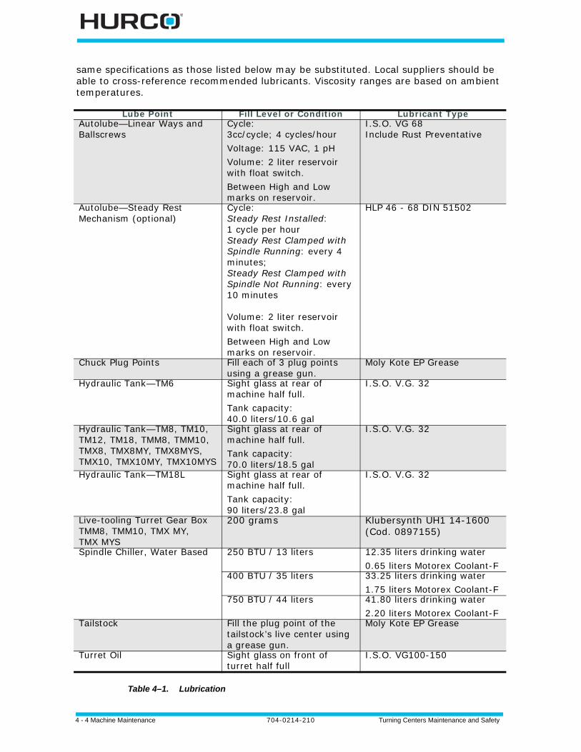
4 - 4 Machine Maintenance 704-0214-210 Turning Centers Maintenance and Safety
same specifications as those listed below may be substituted. Local suppliers should be able to cross-reference recommended lubricants. Viscosity ranges are based on ambient temperatures.
Table 4–1. Lubrication
Lube Point Fill Level or Condition Lubricant TypeAutolube—Linear Ways and Ballscrews
Cycle: 3cc/cycle; 4 cycles/hourVoltage: 115 VAC, 1 pHVolume: 2 liter reservoir with float switch.Between High and Low marks on reservoir.
I.S.O. VG 68Include Rust Preventative
Autolube—Steady Rest Mechanism (optional)
Cycle: Steady Rest Installed: 1 cycle per hourSteady Rest Clamped with Spindle Running: every 4 minutes; Steady Rest Clamped with Spindle Not Running: every 10 minutes
Volume: 2 liter reservoir with float switch.Between High and Low marks on reservoir.
HLP 46 - 68 DIN 51502
Chuck Plug Points Fill each of 3 plug points using a grease gun.
Moly Kote EP Grease
Hydraulic Tank—TM6 Sight glass at rear of machine half full.Tank capacity:40.0 liters/10.6 gal
I.S.O. V.G. 32
Hydraulic Tank—TM8, TM10, TM12, TM18, TMM8, TMM10, TMX8, TMX8MY, TMX8MYS, TMX10, TMX10MY, TMX10MYS
Sight glass at rear of machine half full.Tank capacity:70.0 liters/18.5 gal
I.S.O. V.G. 32
Hydraulic Tank—TM18L Sight glass at rear of machine half full.Tank capacity:90 liters/23.8 gal
I.S.O. V.G. 32
Live-tooling Turret Gear Box TMM8, TMM10, TMX MY, TMX MYS
200 grams Klubersynth UH1 14-1600 (Cod. 0897155)
Spindle Chiller, Water Based 250 BTU / 13 liters 12.35 liters drinking water0.65 liters Motorex Coolant-F
400 BTU / 35 liters 33.25 liters drinking water1.75 liters Motorex Coolant-F
750 BTU / 44 liters 41.80 liters drinking water2.20 liters Motorex Coolant-F
Tailstock Fill the plug point of the tailstock’s live center using a grease gun.
Moly Kote EP Grease
Turret Oil Sight glass on front of turret half full
I.S.O. VG100-150
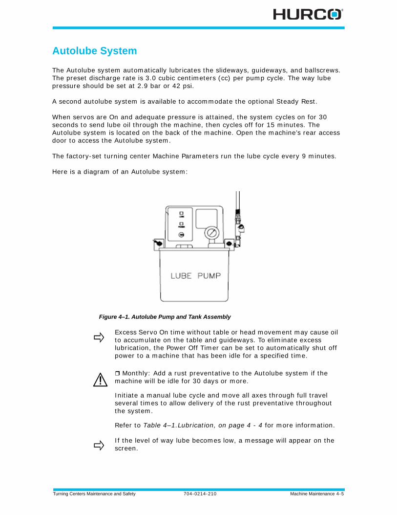
Turning Centers Maintenance and Safety 704-0214-210 Machine Maintenance 4-5
Autolube System
The Autolube system automatically lubricates the slideways, guideways, and ballscrews. The preset discharge rate is 3.0 cubic centimeters (cc) per pump cycle. The way lube pressure should be set at 2.9 bar or 42 psi.
A second autolube system is available to accommodate the optional Steady Rest.
When servos are On and adequate pressure is attained, the system cycles on for 30 seconds to send lube oil through the machine, then cycles off for 15 minutes. The Autolube system is located on the back of the machine. Open the machine’s rear access door to access the Autolube system.
The factory-set turning center Machine Parameters run the lube cycle every 9 minutes.
Here is a diagram of an Autolube system:
Figure 4–1. Autolube Pump and Tank Assembly
Excess Servo On time without table or head movement may cause oil to accumulate on the table and guideways. To eliminate excess lubrication, the Power Off Timer can be set to automatically shut off power to a machine that has been idle for a specified time.
Monthly: Add a rust preventative to the Autolube system if the machine will be idle for 30 days or more.
Initiate a manual lube cycle and move all axes through full travel several times to allow delivery of the rust preventative throughout the system.
Refer to Table 4–1.Lubrication, on page 4 - 4 for more information.
If the level of way lube becomes low, a message will appear on the screen.
4 - 6 Machine Maintenance 704-0214-210 Turning Centers Maintenance and Safety
Maintain Autolube Filler Filter Screen and Autolube Fluid Level
Monthly: Maintain the autolube fluid level and check the filler filter screen.
The filter screen inside the oil filler section of the tank prevents contamination from entering the system. The filter screen must be checked and replaced if it becomes plugged. The autolube oil must be replaced monthly.
1. Lift the oil filler cap and check the filter screen. If the screen is dirty or clogged, clean and dry the screen before reinstalling it.
2. The oil level should be between the high and low marks (about 1/2 inch or 1.25 cm from top cover of tank). If needed, add oil to the tank. Refer to Table 4–1.Lubrication, on page 4 - 4 for oil type.
3. Replace the oil filler cap.
4.
Clean Autolube Tank and Suction Pump Filter
Annually or at about every 2000 hours of use: Clean the autolube reservoir tank and suction filter.
1. Shut off power to the machine.
2. Loosen and remove the two thumbscrews that secure the reservoir to its mounting bracket.
3. Lower the reservoir downward from the threaded spacers.
4. Remove the suction filter group by first carefully prying out the retaining ring.
5. Noting the order of assembly, remove the suction filter discs and screws.
6. Insert the new coarse screen (filter disc support), fine screen (filter disc, screen disc), filter clamp ring, and retaining ring.
7. Clean any contaminates from the inside of the tank. Dry the inside of the tank with a clean, lint-free cloth.
8. Check the filter screen in the oil filler. It should be clean and undamaged.
9. Make certain the gasket is installed and in good condition.
10. Place the tank on its mounting bracket, guiding it over the threaded spacers.
11.Carefully tighten the two thumb screws that secure the tank to its mounting bracket.
12.Make certain the filter screen is installed in the oil filler.
13. Fill the reservoir with the recommended oil. Refer to Table 4–1.Lubrication, on page 4 - 4.
14.Manually activate the system.
Over-tightening these thumbscrews can damage the tank.
Turning Centers Maintenance and Safety 704-0214-210 Machine Maintenance 4-7
Activate Autolube System
If the turning center has been idle for a long time before powering up, or if the oil has just been replaced, follow these steps to activate the Autolube system:
1. Press the Manual console key to access the Manual screen.
2. Select the DIAGNOSTICS F3 softkey.
3. Select the LUBE F2 softkey. The Lube Diagnostics screen appears.
4. Select the MANUAL LUBE F1 softkey to start the pump. At this point, you may step to the side of the machine and observe the site gauge on the Autolube Pump.
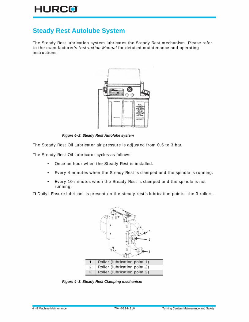
4 - 8 Machine Maintenance 704-0214-210 Turning Centers Maintenance and Safety
Steady Rest Autolube System
The Steady Rest lubrication system lubricates the Steady Rest mechanism. Please refer to the manufacturer’s Instruction Manual for detailed maintenance and operating instructions.
Figure 4–2. Steady Rest Autolube system
The Steady Rest Oil Lubricator air pressure is adjusted from 0.5 to 3 bar.
The Steady Rest Oil Lubricator cycles as follows:
• Once an hour when the Steady Rest is installed.
• Every 4 minutes when the Steady Rest is clamped and the spindle is running.
• Every 10 minutes when the Steady Rest is clamped and the spindle is not running.
Daily: Ensure lubricant is present on the steady rest’s lubrication points: the 3 rollers.
Figure 4–3. Steady Rest Clamping mechanism
1 Roller (lubrication point 1)2 Roller (lubrication point 2)3 Roller (lubrication point 2)
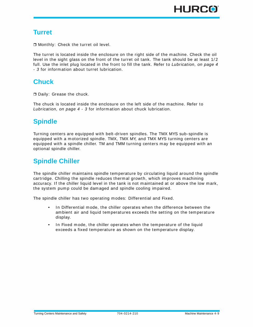
Turning Centers Maintenance and Safety 704-0214-210 Machine Maintenance 4-9
Turret
Monthly: Check the turret oil level.
The turret is located inside the enclosure on the right side of the machine. Check the oil level in the sight glass on the front of the turret oil tank. The tank should be at least 1/2 full. Use the inlet plug located in the front to fill the tank. Refer to Lubrication, on page 4 - 3 for information about turret lubrication.
Chuck
Daily: Grease the chuck.
The chuck is located inside the enclosure on the left side of the machine. Refer to Lubrication, on page 4 - 3 for information about chuck lubrication.
Spindle
Turning centers are equipped with belt-driven spindles. The TMX MYS sub-spindle is equipped with a motorized spindle. TMX, TMX MY, and TMX MYS turning centers are equipped with a spindle chiller. TM and TMM turning centers may be equipped with an optional spindle chiller.
Spindle Chiller
The spindle chiller maintains spindle temperature by circulating liquid around the spindle cartridge. Chilling the spindle reduces thermal growth, which improves machining accuracy. If the chiller liquid level in the tank is not maintained at or above the low mark, the system pump could be damaged and spindle cooling impaired.
The spindle chiller has two operating modes: Differential and Fixed.
• In Differential mode, the chiller operates when the difference between the ambient air and liquid temperatures exceeds the setting on the temperature display.
• In Fixed mode, the chiller operates when the temperature of the liquid exceeds a fixed temperature as shown on the temperature display.
4 - 10 Machine Maintenance 704-0214-210 Turning Centers Maintenance and Safety
Maintain Spindle Chiller Solution
Weekly: Inspect the chiller solution level (if equipped), and if necessary, add solution to the unit.
Follow these steps:
1. Check the solution level through the sight gauge on the chiller tank.
2. If the level is low, add the recommended chiller solution to the tank. Refer to Table 4–1.Lubrication, on page 4 - 4 for appropriate lubrication. Do not overfill the tank.
Maintain the Spindle Chiller Tank Air Filter and Water Filter
Weekly or after 40 hours of operation: Inspect the spindle chiller tank air filter and water filter (if equipped) for dirt and damage.
To maintain the spindle chiller air filter screen, follow these steps:
1. Shut off the machine power.
2. Pull the air filter out of the spindle chiller using the black tab located above the control panel. The air filter is positioned horizontally.
3. Inspect the spindle chiller tank air filter.
4. Clean the air filter using a vacuum cleaner, compressed air, or brush and water if the air filter is dirty.
5. Replace the air filter if it is damaged.
6. Inspect the water filter located in the rear of the spindle chiller tank, near the water lines exiting the tank.
7. Replace the water filter cartridge if it is dirty or damaged.
Maintain the Spindle Chiller System
Daily or before operation: Maintain the spindle chiller system (if equipped).
Follow these steps:
1. Check the chiller solution level and add solution, if necessary. Refer to Maintain Spindle Chiller Solution, on page 4 - 10.
2. Inspect chiller tubing for bends, tears, or constrictions that may impair flow to the spindle. Replace any damaged tubing.
3. Check the chiller tubing for leaks. Repair or replace if necessary.
4. Check the spindle chiller solution for presence of contaminates; sediment in the solution could block tubing.
5. Replace contaminated solution. Refer to Flush, Clean Tank, and Refill the Chiller Solution in the Spindle Chiller Tank, on page 4 - 11 for instructions.
Use a fully synthetic water miscible corrosion-protection concentrate for spindle cooling systems to protect against corrosion. The additive should not contain any glycols, which can be harmful to galvanized parts.
Turning Centers Maintenance and Safety 704-0214-210 Machine Maintenance 4-11
Flush, Clean Tank, and Refill the Chiller Solution in the Spindle Chiller Tank
Annually or every 2000 hours: Flush, clean, and refill the spindle chiller tank (if equipped) once each year and any time the spindle chiller solution shows signs of contamination or overheating.
Follow these steps:
1. Gradually add the flushing agent solution per the flushing agent supplier’s recommendations.
2. Leave machine power on to allow the solution to circulate through the chiller system for 24 hours.
3. Empty the solution.
a. Shut off machine power.b. Locate the drain on the bottom front of the chiller tank.c. Remove the drain plug.d. Use a funnel to drain fluid into a container. Discard the chiller solution per
applicable laws.e. Replace the drain plug.
4. Fill the chiller system with clean chiller solution. Refer to Table 4–1.Lubrication, on page 4 - 4 for appropriate lubricant amounts and types. Do not overfill tank.
Remove Air from Spindle Chiller Circulating System
If air penetrates the circulating system, the flow rate will decrease and there will be noise in the system. To remove air from the circulating system,
1. Turn on the main machine power. This starts the chiller unit, and the pump will start operating.
2. Loosen the pipe slightly at the outlet of the cooler unit to push the air out of the system.
3. Tighten the pipe.
4. Switch off the main machine power.
Repair Leaks in the Spindle Chiller
Leaky pipes can be repaired using tube clips or by replacing the pipes. If welding is required to repair a leaky pipe,
1. Choose a well-ventilated area.
2. Extract all water from the cooler unit.
3. Disconnect all pipes between the machine tool and the cooler unit.
4. Extract refrigerant our of the cooler unit according to the relevant regulations of environmental protection.
4 - 12 Machine Maintenance 704-0214-210 Turning Centers Maintenance and Safety
Operation Checklist
Before operating the spindle chiller,
Daily: Check the spindle chiller (if equipped) to be sure the working environment has appropriate ventilation and the ambient temperature is between 40° and 10° C (104° and 50° F).
Weekly: Check the spindle chiller (if equipped) to be sure there is a sufficient amount of liquid in the tank or in the system.
Refer to Table 4–1.Lubrication, on page 4 - 4 for the amount and type of fluid recommendation.
Follow these safety precautions:
• Keep the spindle chiller in a safe area, free of dampness or moisture.
• Do no stack anything on top of the spindle chiller.
Follow these steps to keep the exterior of the spindle chiller clean:
1. Turn off machine power.
2. Clean the surface of the spindle chiller with cool water, mild detergent, and a lint-free cloth.
3. Wipe electrical components with a dry cloth.
If repairs or replacement parts are required, please follow these safety precautions:
• Turn the machine’s main power switch Off before proceeding.
• Avoid flame near any oil (in the form of liquid or gas).
• Choose a well-ventilated location if releasing refrigerant.
Insufficient liquid within the system will cause damage to the pump.
Restarting the spindle chiller frequently will cause damage to the unit. Do not restart the cooler unit within 3 minutes after turning it off.
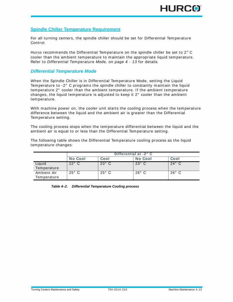
Turning Centers Maintenance and Safety 704-0214-210 Machine Maintenance 4-13
Spindle Chiller Temperature Requirement
For all turning centers, the spindle chiller should be set for Differential Temperature Control.
Hurco recommends the Differential Temperature on the spindle chiller be set to 2° C cooler than the ambient temperature to maintain the appropriate liquid temperature. Refer to Differential Temperature Mode, on page 4 - 13 for details.
Differential Temperature Mode
When the Spindle Chiller is in Differential Temperature Mode, setting the Liquid Temperature to -2° C programs the spindle chiller to constantly maintain the liquid temperature 2° cooler than the ambient temperature. If the ambient temperature changes, the liquid temperature is adjusted to keep it 2° cooler than the ambient temperature.
With machine power on, the cooler unit starts the cooling process when the temperature difference between the liquid and the ambient air is greater than the Differential Temperature setting.
The cooling process stops when the temperature differential between the liquid and the ambient air is equal to or less than the Differential Temperature setting.
The following table shows the Differential Temperature cooling process as the liquid temperature changes:
Table 4–2. Differential Temperature Cooling process
Differential at -2° CNo Cool Cool No Cool Cool
Liquid Temperature
22° C 23° C 23° C 24° C
Ambient Air Temperature
25° C 25° C 26° C 26° C
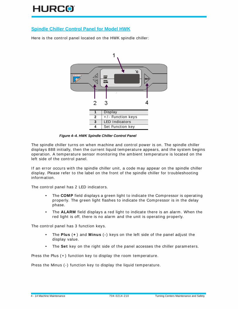
4 - 14 Machine Maintenance 704-0214-210 Turning Centers Maintenance and Safety
Spindle Chiller Control Panel for Model HWK
Here is the control panel located on the HWK spindle chiller:
Figure 4–4. HWK Spindle Chiller Control Panel
The spindle chiller turns on when machine and control power is on. The spindle chiller displays 888 initially, then the current liquid temperature appears, and the system begins operation. A temperature sensor monitoring the ambient temperature is located on the left side of the control panel.
If an error occurs with the spindle chiller unit, a code may appear on the spindle chiller display. Please refer to the label on the front of the spindle chiller for troubleshooting information.
The control panel has 2 LED indicators.
• The COMP field displays a green light to indicate the Compressor is operating properly. The green light flashes to indicate the Compressor is in the delay phase.
• The ALARM field displays a red light to indicate there is an alarm. When the red light is off, there is no alarm and the unit is operating properly.
The control panel has 3 function keys.
• The Plus (+) and Minus (-) keys on the left side of the panel adjust the display value.
• The Set key on the right side of the panel accesses the chiller parameters.
Press the Plus (+) function key to display the room temperature.
Press the Minus (-) function key to display the liquid temperature.
1 Display2 +/- Function keys3 LED Indicators4 Set Function key
Turning Centers Maintenance and Safety 704-0214-210 Machine Maintenance 4-15
Change the Liquid Temperature Setting
Press and hold the Set function key. The display shows 888 initially, then the Liquid Temperature Setting appears. To change this value, press Set again. Then press the Plus (+) or Minus (-) function key.
Hurco recommends setting the value for the Differential Liquid Temperature Setting parameter to -2° C. The default value is +10° C.
To save changes, press and hold the Set function key after making a change. The spindle chiller reverts to the temperature display mode if no further instructions are given within 30 seconds.
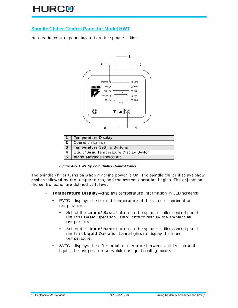
4 - 16 Machine Maintenance 704-0214-210 Turning Centers Maintenance and Safety
Spindle Chiller Control Panel for Model HWT
Here is the control panel located on the spindle chiller:
Figure 4–5. HWT Spindle Chiller Control Panel
The spindle chiller turns on when machine power is On. The spindle chiller displays show dashes followed by the temperatures, and the system operation begins. The objects on the control panel are defined as follows:
• Temperature Display—displays temperature information in LED screens:
• PV°C—displays the current temperature of the liquid or ambient air temperature.
• Select the Liquid/Basic button on the spindle chiller control panel until the Basic Operation Lamp lights to display the ambient air temperature.
• Select the Liquid/Basic button on the spindle chiller control panel until the Liquid Operation Lamp lights to display the liquid temperature.
• SV°C—displays the differential temperature between ambient air and liquid, the temperature at which the liquid cooling occurs.
1 Temperature Display2 Operation Lamps3 Temperature Setting Buttons4 Liquid/Basic Temperature Display Switch5 Alarm Message Indicators
Turning Centers Maintenance and Safety 704-0214-210 Machine Maintenance 4-17
• Operation Lamps—lights indicate operation:
• Liquid—indicates liquid temperature is being displayed in PV°C Temperature Display.
• Basic—indicates ambient air temperature is being displayed in PV°C Temperature Display.
• Pump—indicates the pump is operating.
• Cool—indicates the cooling process is operating.
• Warm—indicates the heater is operating.
• Temperature Setting Buttons—sets the SV°C temperature setting up or down.
• Liquid/Basic Temperature Display Switch—changes the PV°C display from the liquid temperature to the ambient air temperature when pressed. The default display is the liquid temperature.
• Alarm Message Indicator—indicates errors if they occur by illuminating the appropriate light and showing a message in the Temperature Display screens. If an error occurs, the spindle chiller operation stops. Refer to the label on the front of the spindle chiller for more information about alarm messages.
When no lights are illuminated, the spindle chiller is operating properly.
• Pressure—lights when a pressure fault within the refrigeration system occurs.
• Pump—lights when a fault within the pump trips the overload protector.
• Comp.—lights when a fault within the compressor trips the overload protector.
• O.P./Flow—lights when a liquid pressure fault occurs or when there is an insufficient amount of liquid within the liquid circulating system.
• Rev.—lights when the power phase input is reversed.
Setting the SV°C Temperature
To set the SV°C temperature, press the Up or Down arrows on the spindle chiller control panel for at least 0.5 seconds for each press. Hurco recommends keeping the SV°C set at -2° C for Differential Temperature control.
Press the up or down button for at least 0.5 seconds to change the value.
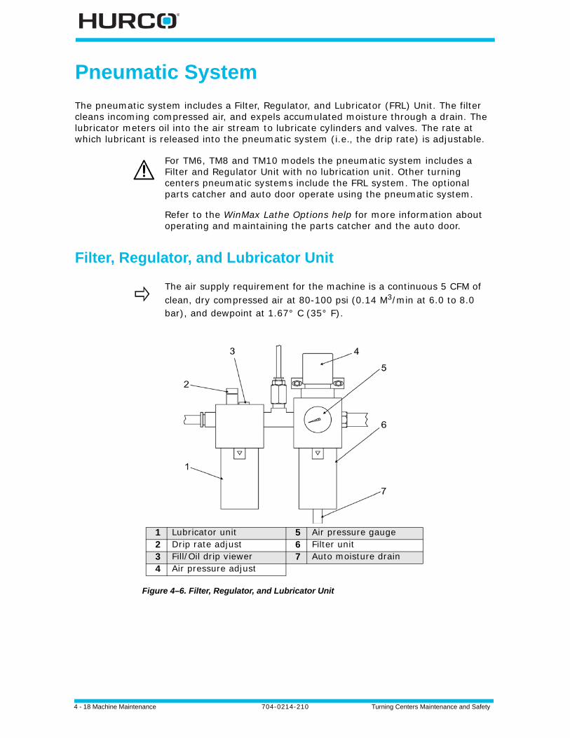
4 - 18 Machine Maintenance 704-0214-210 Turning Centers Maintenance and Safety
Pneumatic System
The pneumatic system includes a Filter, Regulator, and Lubricator (FRL) Unit. The filter cleans incoming compressed air, and expels accumulated moisture through a drain. The lubricator meters oil into the air stream to lubricate cylinders and valves. The rate at which lubricant is released into the pneumatic system (i.e., the drip rate) is adjustable.
Filter, Regulator, and Lubricator Unit
Figure 4–6. Filter, Regulator, and Lubricator Unit
For TM6, TM8 and TM10 models the pneumatic system includes a Filter and Regulator Unit with no lubrication unit. Other turning centers pneumatic systems include the FRL system. The optional parts catcher and auto door operate using the pneumatic system.
Refer to the WinMax Lathe Options help for more information about operating and maintaining the parts catcher and the auto door.
The air supply requirement for the machine is a continuous 5 CFM of clean, dry compressed air at 80-100 psi (0.14 M3/min at 6.0 to 8.0 bar), and dewpoint at 1.67° C (35° F).
1 Lubricator unit 5 Air pressure gauge2 Drip rate adjust 6 Filter unit3 Fill/Oil drip viewer 7 Auto moisture drain4 Air pressure adjust
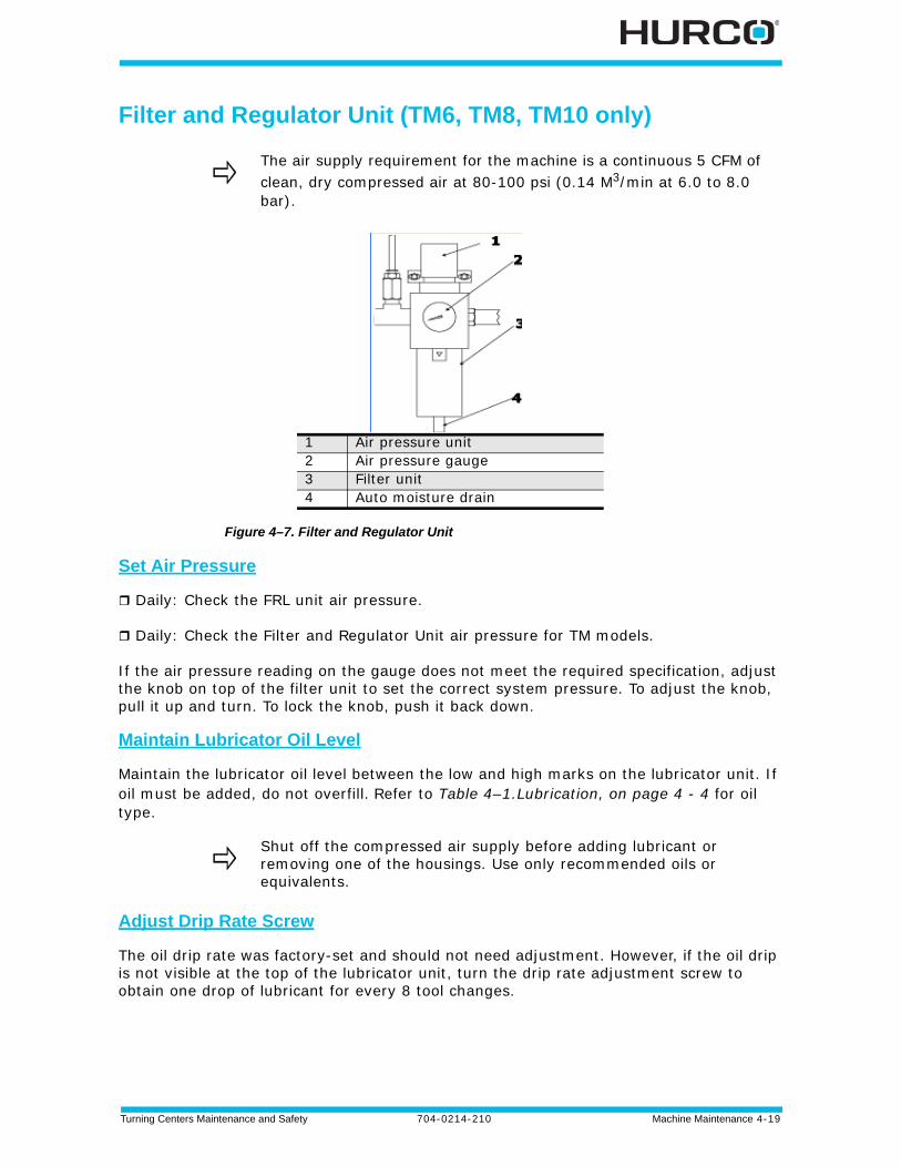
Turning Centers Maintenance and Safety 704-0214-210 Machine Maintenance 4-19
Filter and Regulator Unit (TM6, TM8, TM10 only)
Figure 4–7. Filter and Regulator Unit
Set Air Pressure
Daily: Check the FRL unit air pressure.
Daily: Check the Filter and Regulator Unit air pressure for TM models.
If the air pressure reading on the gauge does not meet the required specification, adjust the knob on top of the filter unit to set the correct system pressure. To adjust the knob, pull it up and turn. To lock the knob, push it back down.
Maintain Lubricator Oil Level
Maintain the lubricator oil level between the low and high marks on the lubricator unit. If oil must be added, do not overfill. Refer to Table 4–1.Lubrication, on page 4 - 4 for oil type.
Adjust Drip Rate Screw
The oil drip rate was factory-set and should not need adjustment. However, if the oil drip is not visible at the top of the lubricator unit, turn the drip rate adjustment screw to obtain one drop of lubricant for every 8 tool changes.
The air supply requirement for the machine is a continuous 5 CFM of clean, dry compressed air at 80-100 psi (0.14 M3/min at 6.0 to 8.0 bar).
1 Air pressure unit2 Air pressure gauge3 Filter unit4 Auto moisture drain
Shut off the compressed air supply before adding lubricant or removing one of the housings. Use only recommended oils or equivalents.
4 - 20 Machine Maintenance 704-0214-210 Turning Centers Maintenance and Safety
Adjust Parts Catcher Speed
You can adjust the speed that the parts catcher moves up and down.
1. Remove the access door on the front of the turning center. The screws are on the inside of the machine.
2. Locate the two brass knobs. Each knob is connected to its own air line feeding pressure to it.
• The knob on the top controls the speed for the upward movement.
• The knob on the bottom controls the speed for the downward movement.
3. Turn the knob (top or bottom) clockwise to lower the speed and counterclockwise to increase the speed.
4. Observe the parts catcher in operation and make adjustments to the knob settings before reattaching the access door.
Check and Replace Air Filter Element
Every 3 Months or every 500 hours: Check the FRL air filter element regularly and replace it for TMX and TMM models.
Every 3 Months or every 500 hours: Clean or replace the air filter element on the Filter and Regulator Unit for TM models.
If the filter becomes clogged, the air pressure may still measure as acceptable, but air flow to the pneumatic system will be restricted.
Check Auto Moisture Drain
Daily: Check the auto moisture drain on FRL.
Weekly: Check the auto moisture drain on the Filter and Regulator Unit for TM models.
Every 3 Months: Drain moisture from the lines of the Filter and Regulator Unit and FRL.
Make sure the auto moisture drain is not stuck open and leaking air. If the drain is stuck open, follow these steps:
1. Disconnect the compressed air supply to the machine.
2. Turn the auto drain nut at the filter unit bottom counter-clockwise one turn.
3. Using a crescent wrench, turn the auto drain nut at the bottom of the filter unit counterclockwise one turn.
4. Tighten the nut clockwise.
First remove the metal bowl guard, then remove the bowl to access the filter element, clean the bowl using a soft, lint-free cloth dabbed with the recommended lubricant. Do not use any type of cleaning fluid.
Before reconnecting the air supply, reinstall the metal bowl guard.
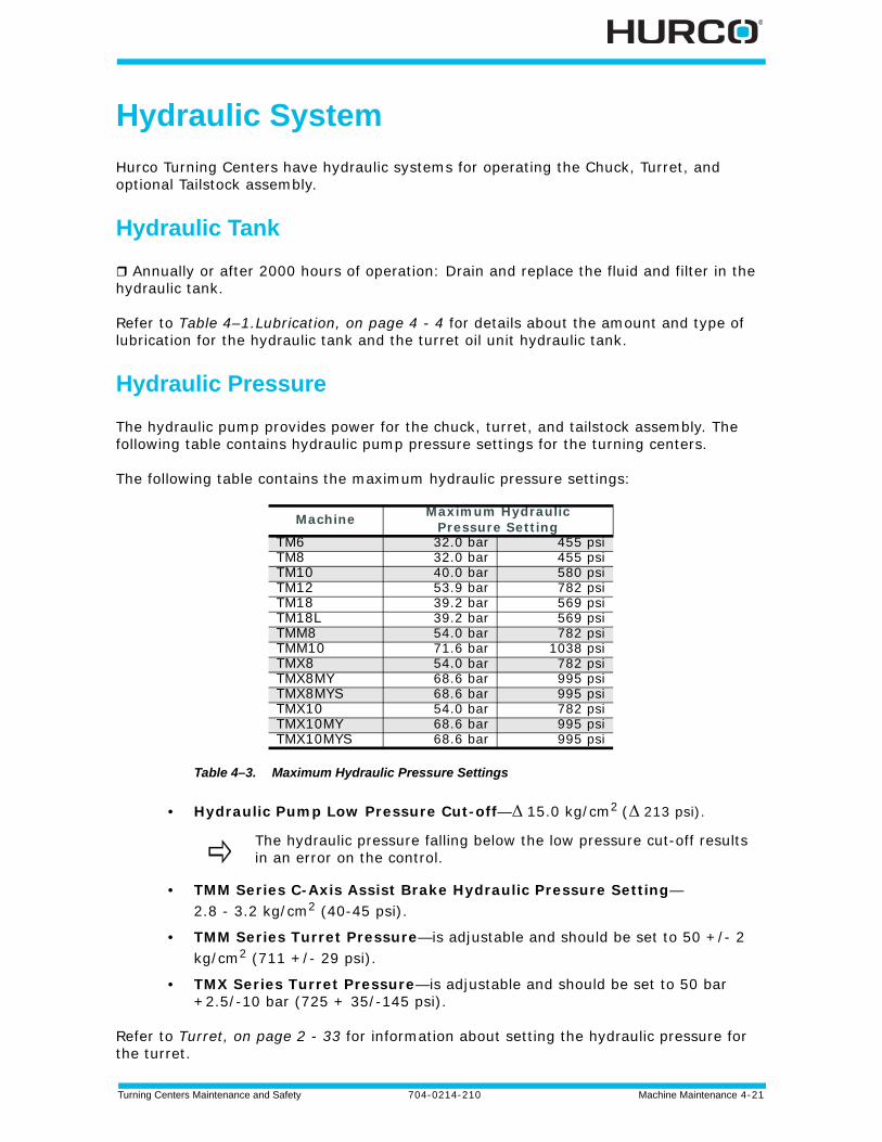
Turning Centers Maintenance and Safety 704-0214-210 Machine Maintenance 4-21
Hydraulic System
Hurco Turning Centers have hydraulic systems for operating the Chuck, Turret, and optional Tailstock assembly.
Hydraulic Tank
Annually or after 2000 hours of operation: Drain and replace the fluid and filter in the hydraulic tank.
Refer to Table 4–1.Lubrication, on page 4 - 4 for details about the amount and type of lubrication for the hydraulic tank and the turret oil unit hydraulic tank.
Hydraulic Pressure
The hydraulic pump provides power for the chuck, turret, and tailstock assembly. The following table contains hydraulic pump pressure settings for the turning centers.
The following table contains the maximum hydraulic pressure settings:
Table 4–3. Maximum Hydraulic Pressure Settings
• Hydraulic Pump Low Pressure Cut-off—Δ 15.0 kg/cm2 (Δ 213 psi).
• TMM Series C-Axis Assist Brake Hydraulic Pressure Setting—2.8 - 3.2 kg/cm2 (40-45 psi).
• TMM Series Turret Pressure—is adjustable and should be set to 50 +/- 2 kg/cm2 (711 +/- 29 psi).
• TMX Series Turret Pressure—is adjustable and should be set to 50 bar +2.5/-10 bar (725 + 35/-145 psi).
Refer to Turret, on page 2 - 33 for information about setting the hydraulic pressure for the turret.
Machine Maximum Hydraulic Pressure Setting
TM6 32.0 bar 455 psiTM8 32.0 bar 455 psiTM10 40.0 bar 580 psiTM12 53.9 bar 782 psiTM18 39.2 bar 569 psiTM18L 39.2 bar 569 psiTMM8 54.0 bar 782 psiTMM10 71.6 bar 1038 psiTMX8 54.0 bar 782 psiTMX8MY 68.6 bar 995 psiTMX8MYS 68.6 bar 995 psiTMX10 54.0 bar 782 psiTMX10MY 68.6 bar 995 psiTMX10MYS 68.6 bar 995 psi
The hydraulic pressure falling below the low pressure cut-off results in an error on the control.
4 - 22 Machine Maintenance 704-0214-210 Turning Centers Maintenance and Safety
Hydraulic Chuck Cylinder Pressure Setting
The chuck hydraulic pressure gauge is located on the front, left side of the enclosure. If there are two gauges, the chuck gauge is the one on the left; the tailstock gauge is on the right.
The amount of hydraulic pressure affects the pressure the jaws apply to the stock. The maximum hydraulic pressure setting for the chuck is 40.8 kg/cm2 (580 psi) for all turning center models.
To adjust the hydraulic pressure for the chuck,
1. Open the door beneath the gauge.
2. If there are two knobs, use the one on the left to adjust the hydraulic pressure for the chuck. Turn the knob locking ring under the pressure adjustment to unlock the knob.
3. Turn the knob clockwise to turn up the pressure for harder stock; turn the knob counterclockwise to turn down the pressure for softer stock.
4. Turn the locking ring clockwise to lock the knob in place.
Hydraulic Tailstock Pressure Gauge Settings
The tailstock hydraulic pressure gauge is located on the front, left side of the enclosure. If there are two gauges, the chuck gauge is the one on the left; the tailstock gauge is on the right.
The amount of hydraulic pressure affects the speed at which the tailstock quill advances or retracts and the force applied by the tailstock.
To adjust the hydraulic pressure for the tailstock,
1. Open the door beneath the gauge.
2. If there are two knobs, use the one on the right to adjust the hydraulic pressure for the tailstock. Turn the knob locking ring on the pressure adjustment to unlock the knob.
3. Turn the knob clockwise to turn up the pressure for harder stock; turn the knob counterclockwise to turn down the pressure for softer stock.
When the quill is advanced, the pressure can only be adjusted higher because of the check valve. To lower the pressure when the quill is advanced,
1. Retract the quill.2. Turn the knob counterclockwise to lower the pressure setting.3. Advance the tailstock.4. Turn the knob clockwise to the desired pressure.

Turning Centers Maintenance and Safety 704-0214-210 Machine Maintenance 4-23
4. Turn the locking ring clockwise to lock the knob in place.
You can also use the flow control valve located inside the left enclosure door to adjust the flow of the tailstock’s movement. Open the door on the left side of the turning center to access the control valve. This adjustment keeps the pressure set the same but makes the tailstock move faster or slower.
4 - 24 Machine Maintenance 704-0214-210 Turning Centers Maintenance and Safety
Flood Coolant and Washdown System
The flood coolant system pumps coolant to the tool in the turret.The washdown system uses a large flow of coolant to move chips to the front of the machine and onto the chip conveyor. A washdown spray gun is externally mounted on the machine to spray chips found inside the enclosure.
Chips that are flushed out of the machining center collect in the chip conveyor tank. Used coolant is cleaned of chips and oil and recirculated into the coolant tank. Filters remove contaminants from the coolant.
Selecting Coolant
Use the recommended coolant to prevent damage to the machine oil, guideways, precision ballscrews, and painted surfaces. Use a non- or semi-synthetic water soluble coolant. Coolant should have these qualities:
• Suitable for the workpiece material and machining operation.• Soluble in water.• Mineral content of at least 35%. When synthetic coolants and coolants that
contain too little mineral oil come in contact with guideway lube oil, they can clog the guideways.
• Adequate rust protection.• Anti-foam, anti-bacterial, and anti-fungal agents.• No skin irritation when prepared to manufacturer specifications.• Penetrating lubrication oil should float on the surface of the coolant (instead
of dissolving in the coolant).• No aggressive additives. However, suitable additives can increase cutting
capacity.
Preparing Coolant
Follow these guidelines when preparing coolant:
• Mix the coolant according to manufacturer instructions. Use deionized (preferred) or softened water for the coolant mixture. To prevent zinc contamination, do not store coolant in a galvanized container.
• Check coolant concentration regularly with a refractometer or by titration.
• Screen off any residue floating in the coolant.
• Use coolant additives such as bactericides, fungicides, and anti-foam corrosion agents only if recommended by the coolant manufacturer.
• Do not allow foreign matter to mix with the coolant. Contaminated coolant can damage machine parts.
Failure of devices or performance problems related to coolant are not a defect in Hurco’s material or workmanship, and will not be covered by Hurco’s warranty.
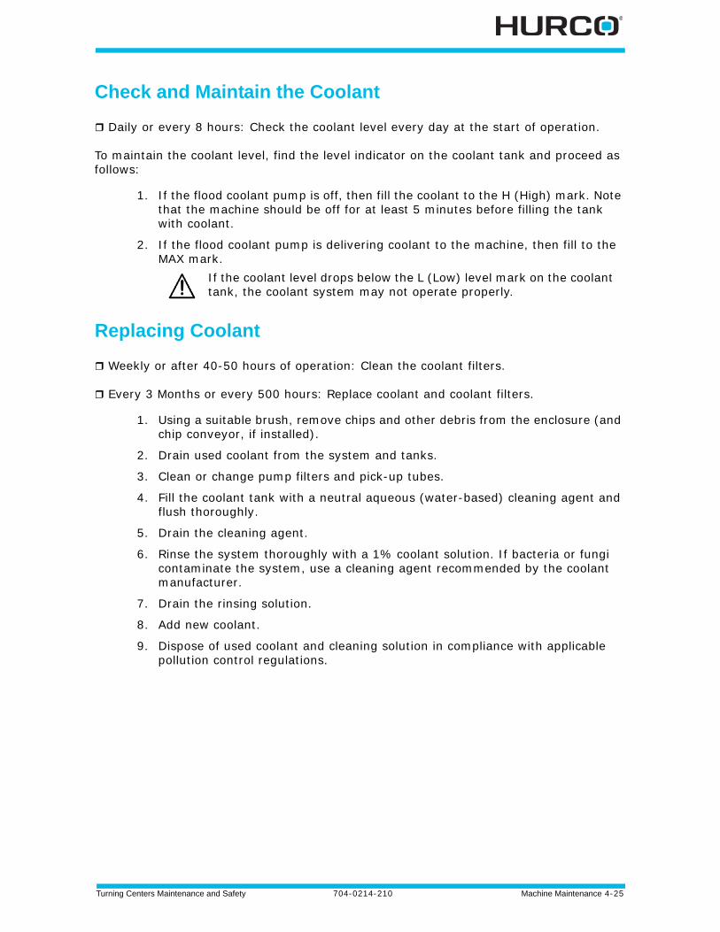
Turning Centers Maintenance and Safety 704-0214-210 Machine Maintenance 4-25
Check and Maintain the Coolant
Daily or every 8 hours: Check the coolant level every day at the start of operation.
To maintain the coolant level, find the level indicator on the coolant tank and proceed as follows:
1. If the flood coolant pump is off, then fill the coolant to the H (High) mark. Note that the machine should be off for at least 5 minutes before filling the tank with coolant.
2. If the flood coolant pump is delivering coolant to the machine, then fill to the MAX mark.
Replacing Coolant
Weekly or after 40-50 hours of operation: Clean the coolant filters.
Every 3 Months or every 500 hours: Replace coolant and coolant filters.
1. Using a suitable brush, remove chips and other debris from the enclosure (and chip conveyor, if installed).
2. Drain used coolant from the system and tanks.
3. Clean or change pump filters and pick-up tubes.
4. Fill the coolant tank with a neutral aqueous (water-based) cleaning agent and flush thoroughly.
5. Drain the cleaning agent.
6. Rinse the system thoroughly with a 1% coolant solution. If bacteria or fungi contaminate the system, use a cleaning agent recommended by the coolant manufacturer.
7. Drain the rinsing solution.
8. Add new coolant.
9. Dispose of used coolant and cleaning solution in compliance with applicable pollution control regulations.
If the coolant level drops below the L (Low) level mark on the coolant tank, the coolant system may not operate properly.
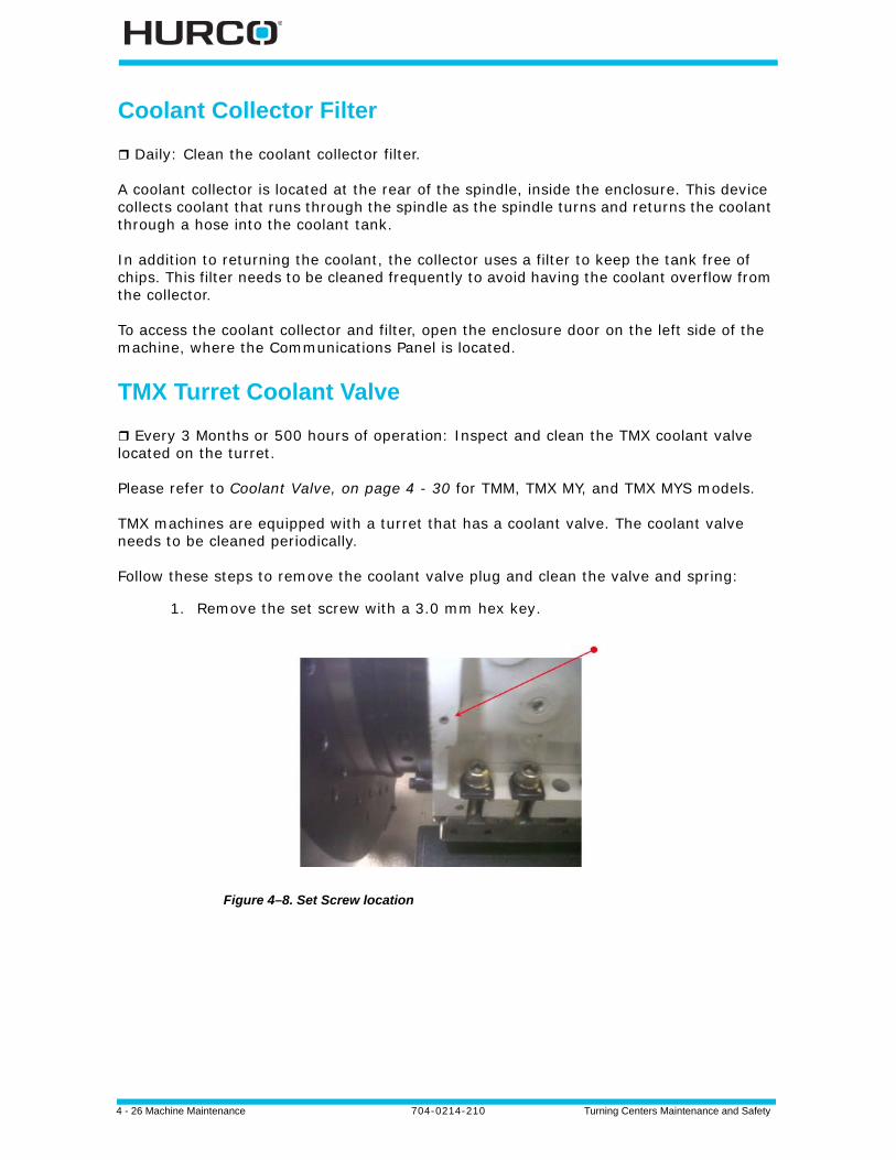
4 - 26 Machine Maintenance 704-0214-210 Turning Centers Maintenance and Safety
Coolant Collector Filter
Daily: Clean the coolant collector filter.
A coolant collector is located at the rear of the spindle, inside the enclosure. This device collects coolant that runs through the spindle as the spindle turns and returns the coolant through a hose into the coolant tank.
In addition to returning the coolant, the collector uses a filter to keep the tank free of chips. This filter needs to be cleaned frequently to avoid having the coolant overflow from the collector.
To access the coolant collector and filter, open the enclosure door on the left side of the machine, where the Communications Panel is located.
TMX Turret Coolant Valve
Every 3 Months or 500 hours of operation: Inspect and clean the TMX coolant valve located on the turret.
Please refer to Coolant Valve, on page 4 - 30 for TMM, TMX MY, and TMX MYS models.
TMX machines are equipped with a turret that has a coolant valve. The coolant valve needs to be cleaned periodically.
Follow these steps to remove the coolant valve plug and clean the valve and spring:
1. Remove the set screw with a 3.0 mm hex key.
Figure 4–8. Set Screw location
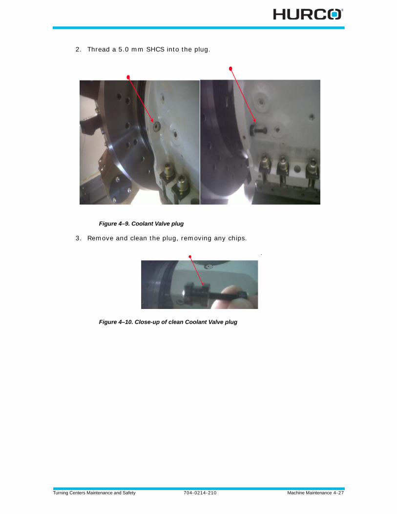
Turning Centers Maintenance and Safety 704-0214-210 Machine Maintenance 4-27
2. Thread a 5.0 mm SHCS into the plug.
Figure 4–9. Coolant Valve plug
3. Remove and clean the plug, removing any chips.
Figure 4–10. Close-up of clean Coolant Valve plug
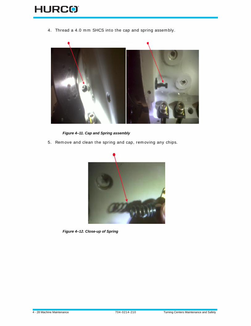
4 - 28 Machine Maintenance 704-0214-210 Turning Centers Maintenance and Safety
4. Thread a 4.0 mm SHCS into the cap and spring assembly.
Figure 4–11. Cap and Spring assembly
5. Remove and clean the spring and cap, removing any chips.
Figure 4–12. Close-up of Spring
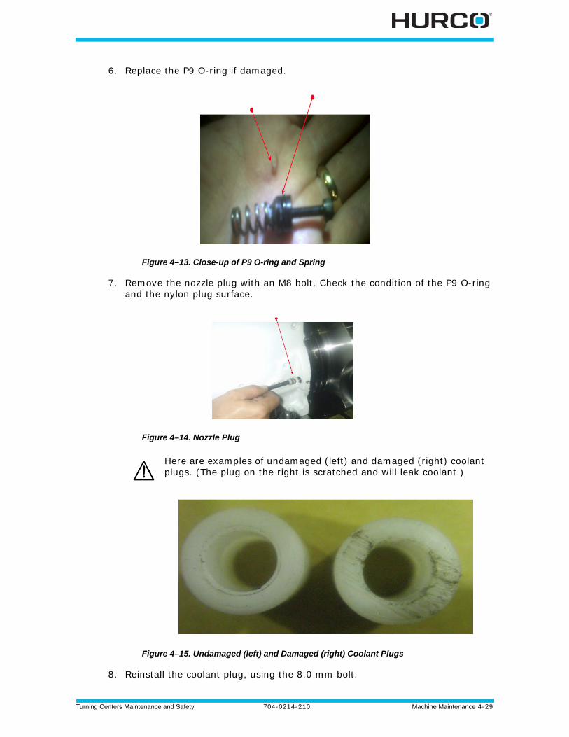
Turning Centers Maintenance and Safety 704-0214-210 Machine Maintenance 4-29
6. Replace the P9 O-ring if damaged.
Figure 4–13. Close-up of P9 O-ring and Spring
7. Remove the nozzle plug with an M8 bolt. Check the condition of the P9 O-ring and the nylon plug surface.
Figure 4–14. Nozzle Plug
Figure 4–15. Undamaged (left) and Damaged (right) Coolant Plugs
8. Reinstall the coolant plug, using the 8.0 mm bolt.
Here are examples of undamaged (left) and damaged (right) coolant plugs. (The plug on the right is scratched and will leak coolant.)
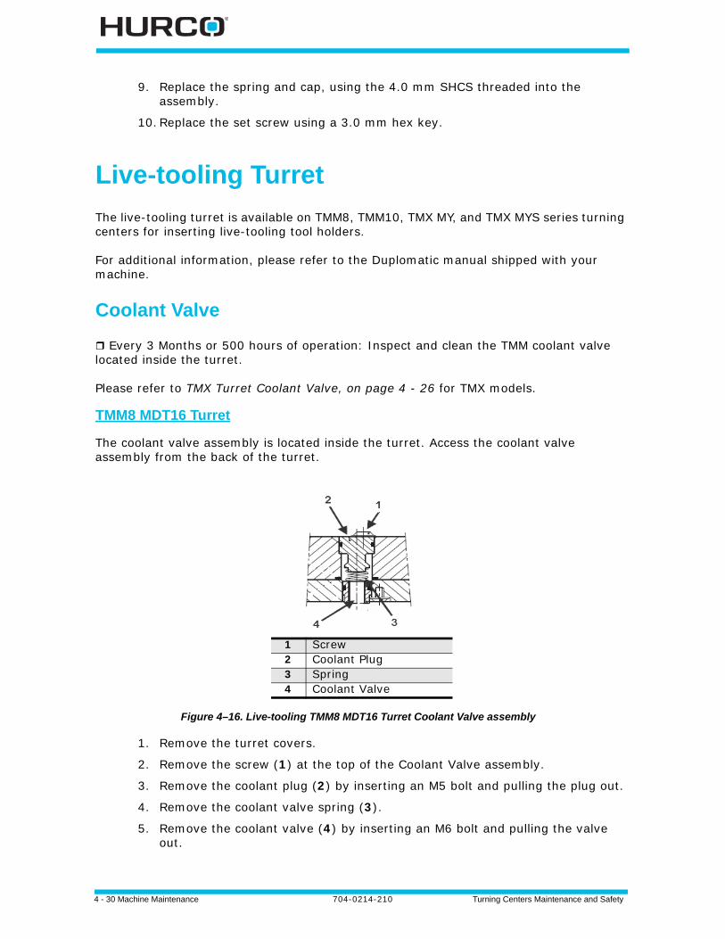
4 - 30 Machine Maintenance 704-0214-210 Turning Centers Maintenance and Safety
9. Replace the spring and cap, using the 4.0 mm SHCS threaded into the assembly.
10.Replace the set screw using a 3.0 mm hex key.
Live-tooling Turret
The live-tooling turret is available on TMM8, TMM10, TMX MY, and TMX MYS series turning centers for inserting live-tooling tool holders.
For additional information, please refer to the Duplomatic manual shipped with your machine.
Coolant Valve
Every 3 Months or 500 hours of operation: Inspect and clean the TMM coolant valve located inside the turret.
Please refer to TMX Turret Coolant Valve, on page 4 - 26 for TMX models.
TMM8 MDT16 Turret
The coolant valve assembly is located inside the turret. Access the coolant valve assembly from the back of the turret.
Figure 4–16. Live-tooling TMM8 MDT16 Turret Coolant Valve assembly
1. Remove the turret covers.
2. Remove the screw (1) at the top of the Coolant Valve assembly.
3. Remove the coolant plug (2) by inserting an M5 bolt and pulling the plug out.
4. Remove the coolant valve spring (3).
5. Remove the coolant valve (4) by inserting an M6 bolt and pulling the valve out.
1 Screw 2 Coolant Plug3 Spring4 Coolant Valve
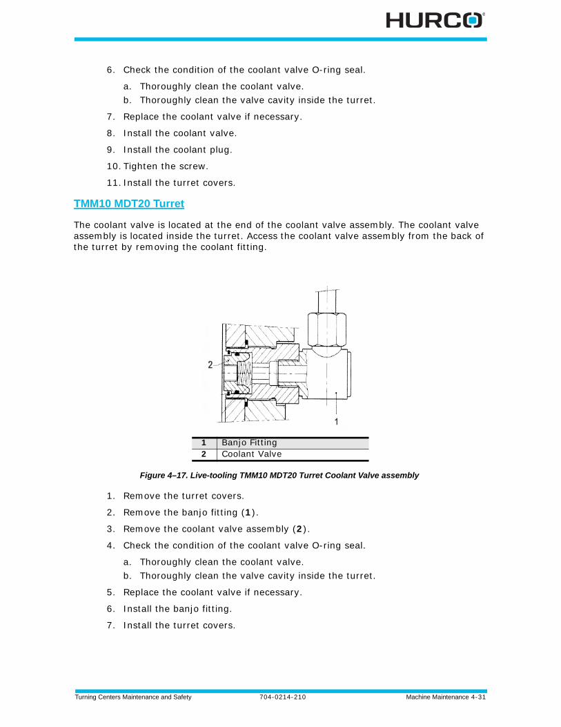
Turning Centers Maintenance and Safety 704-0214-210 Machine Maintenance 4-31
6. Check the condition of the coolant valve O-ring seal.
a. Thoroughly clean the coolant valve.b. Thoroughly clean the valve cavity inside the turret.
7. Replace the coolant valve if necessary.
8. Install the coolant valve.
9. Install the coolant plug.
10. Tighten the screw.
11. Install the turret covers.
TMM10 MDT20 Turret
The coolant valve is located at the end of the coolant valve assembly. The coolant valve assembly is located inside the turret. Access the coolant valve assembly from the back of the turret by removing the coolant fitting.
Figure 4–17. Live-tooling TMM10 MDT20 Turret Coolant Valve assembly
1. Remove the turret covers.
2. Remove the banjo fitting (1).
3. Remove the coolant valve assembly (2).
4. Check the condition of the coolant valve O-ring seal.
a. Thoroughly clean the coolant valve.b. Thoroughly clean the valve cavity inside the turret.
5. Replace the coolant valve if necessary.
6. Install the banjo fitting.
7. Install the turret covers.
1 Banjo Fitting2 Coolant Valve
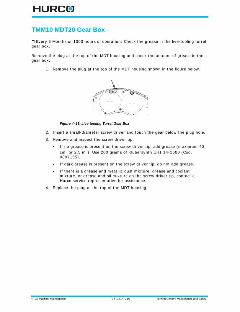
4 - 32 Machine Maintenance 704-0214-210 Turning Centers Maintenance and Safety
TMM10 MDT20 Gear Box
Every 6 Months or 1000 hours of operation: Check the grease in the live-tooling turret gear box.
Remove the plug at the top of the MDT housing and check the amount of grease in the gear box.
1. Remove the plug at the top of the MDT housing shown in the figure below.
Figure 4–18. Live-tooling Turret Gear Box
2. Insert a small-diameter screw driver and touch the gear below the plug hole.
3. Remove and inspect the screw driver tip:
• If no grease is present on the screw driver tip, add grease (maximum 40 cm3 or 2.5 in3). Use 200 grams of Klubersynth UH1 14-1600 (Cod. 0897155).
• If dark grease is present on the screw driver tip, do not add grease.
• If there is a grease and metallic dust mixture, grease and coolant mixture, or grease and oil mixture on the screw driver tip, contact a Hurco service representative for assistance.
4. Replace the plug at the top of the MDT housing.
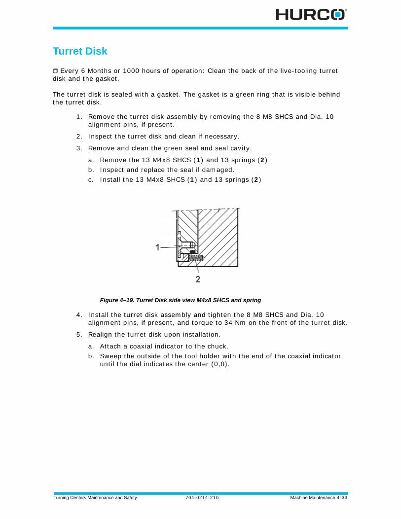
Turning Centers Maintenance and Safety 704-0214-210 Machine Maintenance 4-33
Turret Disk
Every 6 Months or 1000 hours of operation: Clean the back of the live-tooling turret disk and the gasket.
The turret disk is sealed with a gasket. The gasket is a green ring that is visible behind the turret disk.
1. Remove the turret disk assembly by removing the 8 M8 SHCS and Dia. 10 alignment pins, if present.
2. Inspect the turret disk and clean if necessary.
3. Remove and clean the green seal and seal cavity.
a. Remove the 13 M4x8 SHCS (1) and 13 springs (2)b. Inspect and replace the seal if damaged.c. Install the 13 M4x8 SHCS (1) and 13 springs (2)
Figure 4–19. Turret Disk side view M4x8 SHCS and spring
4. Install the turret disk assembly and tighten the 8 M8 SHCS and Dia. 10 alignment pins, if present, and torque to 34 Nm on the front of the turret disk.
5. Realign the turret disk upon installation.
a. Attach a coaxial indicator to the chuck.b. Sweep the outside of the tool holder with the end of the coaxial indicator
until the dial indicates the center (0,0).
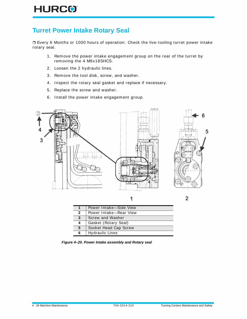
4 - 34 Machine Maintenance 704-0214-210 Turning Centers Maintenance and Safety
Turret Power Intake Rotary Seal
Every 6 Months or 1000 hours of operation: Check the live-tooling turret power intake rotary seal.
1. Remove the power intake engagement group on the rear of the turret by removing the 4 M6x18SHCS.
2. Loosen the 2 hydraulic lines.
3. Remove the tool disk, screw, and washer.
4. Inspect the rotary seal gasket and replace if necessary.
5. Replace the screw and washer.
6. Install the power intake engagement group.
Figure 4–20. Power Intake assembly and Rotary seal
1 Power Intake—Side View2 Power Intake—Rear View3 Screw and Washer4 Gasket (Rotary Seal)5 Socket Head Cap Screw6 Hydraulic Lines
Turning Centers Maintenance and Safety 704-0214-210 Machine Maintenance 4-35
Steady Rest
TM12 and TM18 series machines may be equipped with an optional SMW-AUTOBLOK Steady Rest device. The device supports long thin stock at its mid-point. Please refer to WinMax Lathe Options for programming information.
Daily: Check Steady Rest lubrication points (on the 3 rollers and on the center arm). Lubricant must be present at these points.
Monthly: If compressed air is used, remove the drain plug and open the Steady Rest drain. (The location is located on the Steady Rest label.) Ensure that air can pass through. Replace the plug to close the drain.
Annually: Disassemble and clean the Steady Rest.
Annually: Check the Steady Rest safety valve.
Please refer to the manufacturer’s Instruction Manual, located in the machine electrical cabinet, for complete details regarding installation and maintenance.
4 - 36 Machine Maintenance 704-0214-210 Turning Centers Maintenance and Safety
Chip Conveyor
The chip conveyor is optional with some models. The chip conveyor runs along the machine base.
Chip Conveyor Tank and Screens
Daily: Clean the chip conveyor tank (if equipped) chip screens.
Every 3 Months or after 500 hours of operation: Clean the chip conveyor tank (if equipped) whenever the coolant is replaced.
Chips that are not flushed out of the machine collect in the chip conveyor tank.
To clean the tank:
1. Attach a hose to the plug located in the front of the chip conveyor tank to drain the contaminated coolant.
2. Pull the tank forward and remove any remaining chips from the tank with a soft brush.
3. Remove the two chip screens from the coolant tank.
4. Rinse the screens and dry, before replacing them.
Chip Conveyor Paddle Screws and Chains
Every 6 Months: Inspect the chip conveyor chains and paddle screws (if equipped) for tightness.
There are two types of chip conveyors: drag flight and belt.
Drag Flight
The drag flight operates with paddles that pull the chips toward the conveyor for disposal. There are 3 button head screws on each end of the drag flight paddles. These screws need to be checked for tightness. If any screws are loose, tighten the screws.
The drag flight paddles move with sprockets and chains located on the inside of each side of the chip conveyor. Check the chains for looseness and tighten if necessary.
Belt
The belt type operates by collecting the chips on top of a belt moving to the conveyor for disposal. The belt runs on guides with sprockets and chains located on the inside of each side of the chip conveyor. Check the chains for looseness and tighten if necessary.
Turning Centers Maintenance and Safety 704-0214-210 Machine Maintenance 4-37
Limit Switches and Dogs
Monthly or 150-200 hours of operation: Inspect limit switches and dog fasteners for damage.
Limit switches and dogs are mounted on each axis and are used to determine end-of-travel and to establish reference points for initial machine zeroes.
1. Open the rear-access panel above the hydraulic pump so you can see the limit switches and dogs.
2. Use the jog unit to position the axes at mid-travel.
3. Check the tightness of limit switch and dog fasteners.
Machine Electrical Ground
Every 3 Months: Measure the ground impedance (resistance to true earth).
The ground for the machine is located inside the control cabinet, near the disconnect switch.
Machine Level
Every 6 Months or every 1000 hours: Verify the machine is sitting level.
Place a precision level (resolution 0.0005 in/ft.) parallel and perpendicular to the work table leveling plate that bolts onto the turret.
Only a licensed electrician should perform this procedure.
4 - 38 Machine Maintenance 704-0214-210 Turning Centers Maintenance and Safety
Enclosure Windows
Daily: Inspect the enclosure windows for scratches, damage, cracks, or other deformities that could adversely affect the impact resistance.
Polycarbonate Panels which are used as viewing window of machines are subject to significant deterioration in its impact resistance due to the action of metal working fluids and other lubricants. The degradation process depends on the amount and type of fluids and can lead to a loss of approximately 10% of panel’s impact resistance per year. It is the operator’s responsibility to ensure that the control measures for ejections of work pieces and/or chuck jaw are sufficient for the hazard and that the control measures are in proportion to the risk.
Hurco recommends that the user contact your Hurco representative for application of safety film or replacement glass periodically to ensure the proper corrective action is taken.
Spindle Run-in or Cycle Procedure
Monthly: Perform a spindle run-in before operating the machine if the spindle has been idle for more than 30 days or if the spindle has never been used.
1. Referring to the appropriate Max RPM Spindle table that follows, run the spindle for the indicated time, at the recommended speeds, depending on your maximum spindle speed. Proceed in the order listed in the table.
2. Monitor the temperature at either the front or upper bearing and either the rear or lower bearing (depending on the type of machine), both of which should not exceed 55º C (130º F) once the maximum RPM is achieved.
3. If spindle flange temperature does not exceed 55º C (130º F) at any time during the spindle run-in procedure, then the warm-up procedure is complete.
4. If spindle flange temperature exceeds 55º C (130º F) at any time during the spindle warm-up, then stop the spindle immediately. Allow the spindle to cool to room temperature.
5. Restart the warm-up procedure at the last speed used prior to the temperature spike.
6. Repeat steps 1-3 above until the spindle runs at each specified RPM for the time specified, below 55º C (130º F).
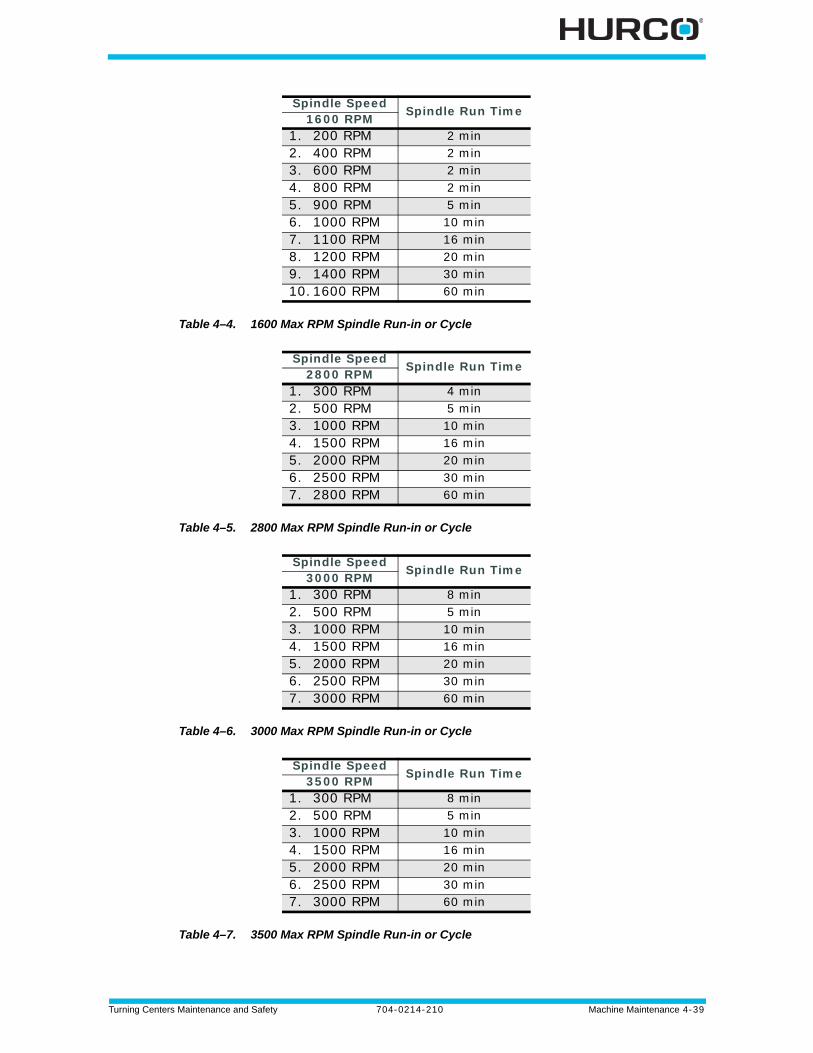
Turning Centers Maintenance and Safety 704-0214-210 Machine Maintenance 4-39
Table 4–4. 1600 Max RPM Spindle Run-in or Cycle
Table 4–5. 2800 Max RPM Spindle Run-in or Cycle
Table 4–6. 3000 Max RPM Spindle Run-in or Cycle
Table 4–7. 3500 Max RPM Spindle Run-in or Cycle
Spindle Speed Spindle Run Time1600 RPM1. 200 RPM 2 min2. 400 RPM 2 min3. 600 RPM 2 min4. 800 RPM 2 min5. 900 RPM 5 min6. 1000 RPM 10 min7. 1100 RPM 16 min8. 1200 RPM 20 min9. 1400 RPM 30 min10.1600 RPM 60 min
Spindle Speed Spindle Run Time2800 RPM1. 300 RPM 4 min2. 500 RPM 5 min3. 1000 RPM 10 min4. 1500 RPM 16 min5. 2000 RPM 20 min6. 2500 RPM 30 min7. 2800 RPM 60 min
Spindle Speed Spindle Run Time3000 RPM1. 300 RPM 8 min2. 500 RPM 5 min3. 1000 RPM 10 min4. 1500 RPM 16 min5. 2000 RPM 20 min6. 2500 RPM 30 min7. 3000 RPM 60 min
Spindle Speed Spindle Run Time3500 RPM1. 300 RPM 8 min2. 500 RPM 5 min3. 1000 RPM 10 min4. 1500 RPM 16 min5. 2000 RPM 20 min6. 2500 RPM 30 min7. 3000 RPM 60 min
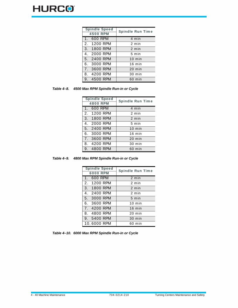
4 - 40 Machine Maintenance 704-0214-210 Turning Centers Maintenance and Safety
Table 4–8. 4500 Max RPM Spindle Run-in or Cycle
Table 4–9. 4800 Max RPM Spindle Run-in or Cycle
Table 4–10. 6000 Max RPM Spindle Run-in or Cycle
Spindle Speed Spindle Run Time4500 RPM1. 600 RPM 4 min2. 1200 RPM 2 min3. 1800 RPM 2 min4. 2000 RPM 5 min5. 2400 RPM 10 min6. 3000 RPM 16 min7. 3600 RPM 20 min8. 4200 RPM 30 min9. 4500 RPM 60 min
Spindle Speed Spindle Run Time4800 RPM1. 600 RPM 4 min2. 1200 RPM 2 min3. 1800 RPM 2 min4. 2000 RPM 5 min5. 2400 RPM 10 min6. 3000 RPM 16 min7. 3600 RPM 20 min8. 4200 RPM 30 min9. 4800 RPM 60 min
Spindle Speed Spindle Run Time6000 RPM1. 600 RPM 2 min2. 1200 RPM 2 min3. 1800 RPM 2 min4. 2400 RPM 2 min5. 3000 RPM 5 min6. 3600 RPM 10 min7. 4200 RPM 16 min8. 4800 RPM 20 min9. 5400 RPM 30 min10.6000 RPM 60 min
Turning Centers Maintenance and Safety 704-0214-210 Machine Maintenance 4-41
Troubleshooting
Failure conditions can be evident during power up and operation. Failure detection and prevention descriptions follow.
Power-Up Troubleshooting
If a problem occurs during power up, look for one of the following symptoms:
No Response on the Console
If no messages appear on the text screen after switching the power on, make sure of the following:
Initialization Error Messages
After power has been switched on, initialization messages appear on the text screen. Errors indicated by the following error messages below can be easily remedied.
Before testing live circuits or attempting any repairs to electrical connections, make sure that the power switch on the electrical cabinet is in the Off position. Follow all established safety practices. Remember that the power line from the source to the machine may be live even though the machine tool is not receiving power.
? • No messages appear on the console screen. The system may beep, but does not start up.
• Error messages appear during the initialization process before the Input screen appears.
• Error messages appear on the Input screen.
? • Power supply cord inside the electrical cabinet is properly connected to the power source.
• Power switch on the computer and rack inside the electrical cabinet is in the On position.
“Non-system disk detected. Press any key.”
There is a diskette in the floppy drive (if equipped). Remove the diskette and turn the power off and then back on.
“Security device is invalid or has failed.” The software security device has been removed, is broken, or is not properly connected. Switch off the control and remove the security device. If the device is damaged, replace it. Reconnect the device and switch on the power.

4 - 42 Machine Maintenance 704-0214-210 Turning Centers Maintenance and Safety
Other possible messages during initialization usually indicate missing or corrupted files. The usual solution for such problems is to restore or delete files. For help solving these problems, contact your local Hurco service representative.
Error Messages
If errors occur after power up, take careful note of any error messages on the screen. Note if the red beacon is on or flashing when the error occurs. Also, note if the control responds to any key, button, or touchscreen selection after the error occurs.
Corrective Measures
One or more of the following corrective measures may be necessary:
Check Wiring
Perform these checks:
• Trace the wiring as far as possible.
• Wiggle connectors and ensure they are properly seated.
• Test the connections with an ohmmeter.
• Unplug and reseat circuit boards; sometimes connectors become tarnished and do not conduct well. If the contact points on a printed circuit board (PCB) are dull looking, polish them with a rubber eraser.
Perform a Reset
Technical assistance personnel may ask you to reset a circuit board or the machine.
• To reset a PCB, press the board reset button, if present.
• To reset the machine, switch the main power off and then back on.
Swap Out a Printed Circuit Board
If the PCB is bad or has an intermittent problem, or the connector on the board is not making sufficient contact, then take the PCB out, clean the contacts with a rubber eraser, and reinstall it, taking care to reseat it firmly. If the error is not corrected, remove the board and replace it with a fresh PCB.
Before calling a Hurco service representative for assistance, always switch off the control at the power button, wait a few minutes, and then power on again.If an error message appears, write down the entire message before calling a Hurco service representative for assistance.
Turn off machine power before checking the circuit boards. DO NOT perform any circuit board work with the power on.
Be sure to wear a static-sensitive strap (grounded to the electrical cabinet) before handling any PCB.
Turning Centers Maintenance and Safety 704-0214-210 Machine Maintenance 4-43
Emergency Stop Condition
Pressing the Emergency Stop button removes all servo power and power to the way lubrication pumps. A message on the screen indicates the Emergency Stop condition, and the red beacon lights up.The red icon appears in the status bar, in addition to the red beacon light.
To restore machine power after an Emergency Stop condition:
1. Twist and lift the Emergency Stop Button.
2. Press these console keys in this order:
a. Press the Manual console key.b. Press the Power On button. The Start Cycle button flashes.
c. Press the Start Cycle button to enable the servos.
Machine Diagnostics
The control detects the status of various machine components and presents this information on the Turret Diagnostics screen.
To access the Turret Diagnostics screen, follow these steps:
1. Press the Machine Mode Manual console key.
2. Select the DIAGNOSTICS F3 softkey.
3. Select the TURRET DIAGNOSTICS F1 softkey.
If an error condition is displayed, follow these steps:
1. Follow the instructions on the Turret Diagnostics screen.
2. Once the error status is corrected, select the REFERENCE TURRET F2 softkey to reference the turret.
3. Exit the Turret Diagnostics screen.
There may be more than one Emergency Stop Button on your machine. Know the location of each one.
The system begins processing information about the servos as soon as the button begins flashing. When this processing is complete, a prompt message appears on the screen for you to press the Start Cycle button.
Please refer to the Turret Diagnostics information in the WinMax Lathe On-screen Help for more details about turret diagnostics for your turning center.
4 - 44 Machine Maintenance 704-0214-210 Turning Centers Maintenance and Safety
Common Problems
Common operator problems are listed below, with potential causes and solutions. These problems are usually noticeable without the help of error messages, although error messages may occur. More than one problem can result from a single cause.
Machine operation failures can be a programming or a hardware problem. Hardware includes electronic components, wiring, and electro-mechanical devices.
Power-on Self Test
When you turn on the machine, the control performs a self test. If an error in the control circuitry is detected, a pattern of beeps may sound instead of the normal start-up beep. A screen error message may appear—follow any on-screen instructions.
Machine Voltages
Missing or faulty connections can cause a combination of problems, as listed below.
Table 4–11. Troubleshooting: Missing or Faulty Connections
Fluctuating voltages to the machine may occur when power usage in your region is high (typically on a very hot or cold day). See the following table.
Table 4–12. Troubleshooting: Power Fluctuation
Connections DescriptionMissing • Open grounds
• Open neutrals• Open phase connections• Missing neutral-to-ground strap at main source
Improper • Phase and neutral reversed • Phase and ground reversed• Ground and neutral reversed• Ground and neutral shorted at panel
Loose • At main panels• At equipment• At other equipment in system• At service entrance
Causes Problems Solutions
Power sagFuse blows • Repair faulty in-plant wiring.
• Move any other machines on the circuit to separate circuits.
Power is lostMotor(s) overheat
Power spike
Microprocessor and/or control PC boards fail
• Move any nearby high current switching devices (arc welders, inductive motors) away from the machine.
• Properly ground equipment.• Install surge protection to insulate against
lightning strikes.
Machine stops and/or data is lost.
Turning Centers Maintenance and Safety 704-0214-210 Machine Maintenance 4-45
If a machine malfunction occurs, then consider the following issues:
• Is another machine that uses high current connected to the AC distribution power supply line?
• Is the ground impedance of the AC distribution power supply line sufficient?
• Are there fluctuations in the input voltage to the machine?
• Is there a source of “noise” nearby (crane, welder, etc.)?
• If other CNC or NC machines are connected to the same group of circuits, do any of those machines demonstrate similar problems?
• Was another machine operating at the same time the problem occurred?
• Does the problem occur mainly at a certain time of day?
Coolant System
Refer to the table below if a problem occurs with the coolant system.
Table 4–13. Troubleshooting: Coolant System
Motion and Spindle Rotation
Refer to the table below if a problem occurs with the spindle unit.
Table 4–14. Troubleshooting: Spindle Unit
Power surges can occur when large loads are suddenly placed on, or removed from, an electrical system.
Problem Cause SolutionCoolant flows slowly or stops.
• Clogging due to dirty coolant.
• Pump is not working properly.
• Flush lines, clean filters, drain and refill the system with fresh coolant.
• Check and service the pump. For mist system, check shop air pressure.
Coolant fails to start.
• Coolant is not programmed to be On.
• Coolant pump not working.
• Check the operating mode (auto or manual) or programming.
• Check connector.
Cause SolutionProgram might not have proper RPM setting.
Check the RPM setting in the program. If this setting is wrong, check and correct the entire program.
Spindle drive breaker is tripped. Power down the machine, reset the breaker on the spindle amp, and turn on power.
Override pot is at 0. Move spindle override pot above 0%.
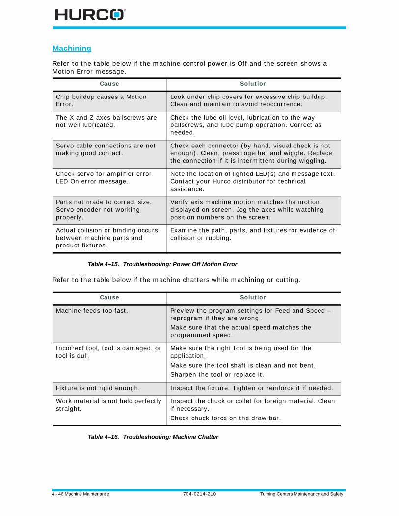
4 - 46 Machine Maintenance 704-0214-210 Turning Centers Maintenance and Safety
Table 4–15. Troubleshooting: Power Off Motion Error
Refer to the table below if the machine chatters while machining or cutting.
Table 4–16. Troubleshooting: Machine Chatter
Machining
Refer to the table below if the machine control power is Off and the screen shows a Motion Error message.
Cause Solution
Chip buildup causes a Motion Error.
Look under chip covers for excessive chip buildup. Clean and maintain to avoid reoccurrence.
The X and Z axes ballscrews are not well lubricated.
Check the lube oil level, lubrication to the way ballscrews, and lube pump operation. Correct as needed.
Servo cable connections are not making good contact.
Check each connector (by hand, visual check is not enough). Clean, press together and wiggle. Replace the connection if it is intermittent during wiggling.
Check servo for amplifier error LED On error message.
Note the location of lighted LED(s) and message text. Contact your Hurco distributor for technical assistance.
Parts not made to correct size. Servo encoder not working properly.
Verify axis machine motion matches the motion displayed on screen. Jog the axes while watching position numbers on the screen.
Actual collision or binding occurs between machine parts and product fixtures.
Examine the path, parts, and fixtures for evidence of collision or rubbing.
Cause Solution
Machine feeds too fast. Preview the program settings for Feed and Speed – reprogram if they are wrong.Make sure that the actual speed matches the programmed speed.
Incorrect tool, tool is damaged, or tool is dull.
Make sure the right tool is being used for the application. Make sure the tool shaft is clean and not bent. Sharpen the tool or replace it.
Fixture is not rigid enough. Inspect the fixture. Tighten or reinforce it if needed.
Work material is not held perfectly straight.
Inspect the chuck or collet for foreign material. Clean if necessary.Check chuck force on the draw bar.
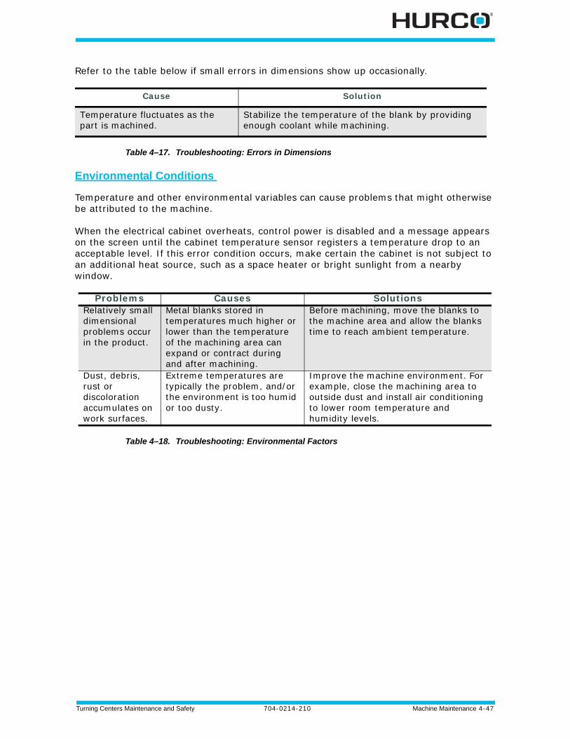
Turning Centers Maintenance and Safety 704-0214-210 Machine Maintenance 4-47
Refer to the table below if small errors in dimensions show up occasionally.
Table 4–17. Troubleshooting: Errors in Dimensions
Environmental Conditions
Temperature and other environmental variables can cause problems that might otherwise be attributed to the machine.
When the electrical cabinet overheats, control power is disabled and a message appears on the screen until the cabinet temperature sensor registers a temperature drop to an acceptable level. If this error condition occurs, make certain the cabinet is not subject to an additional heat source, such as a space heater or bright sunlight from a nearby window.
Table 4–18. Troubleshooting: Environmental Factors
Cause Solution
Temperature fluctuates as the part is machined.
Stabilize the temperature of the blank by providing enough coolant while machining.
Problems Causes SolutionsRelatively small dimensional problems occur in the product.
Metal blanks stored in temperatures much higher or lower than the temperature of the machining area can expand or contract during and after machining.
Before machining, move the blanks to the machine area and allow the blanks time to reach ambient temperature.
Dust, debris, rust or discoloration accumulates on work surfaces.
Extreme temperatures are typically the problem, and/or the environment is too humid or too dusty.
Improve the machine environment. For example, close the machining area to outside dust and install air conditioning to lower room temperature and humidity levels.
4 - 48 Machine Maintenance 704-0214-210 Turning Centers Maintenance and Safety
Ordering Replacement Parts
Hurco maintains a large inventory of service parts. You may order parts from Hurco by telephone, fax, mail, or from your local Hurco Distributor. Contact information is provided during the installation. In addition, Hurco subsidiary contact information can be found on the Hurco Web site: www.hurco.com
Information Required for Parts Orders
For Hurco to process your order and supply you with the correct part(s), you must provide the detailed information described below:
• Serial Number index of the Hurco machine. The machine serial number is located on the identification/data plate, which is attached to the electrical cabinet door.
• Your company purchase order number.
• The part number, part name (description) and quantity desired. State where you found the part number. If you found it in a manual, include the manual part number, revision or date, and page the part was found on.
• Your company name and complete address.
• Name and telephone number of person ordering the parts.
• Indicate the condition of the machine (e.g., inoperable or functional).
• Provide the billing address to which invoices are to be mailed.
• Provide the shipping address, as well as any special shipping instructions, including mode of shipment, the department and person to ship to, and the delivery date requested.
Returning Parts
You must contact Hurco to receive a Return Materials Authorization (RMA) number before returning a part. The RMA number must be written on the outside of the container used to ship the returned part.
All parts are subject to inspection before credit is issued.
All defective parts replaced under warranty agreement must be returned within 30 days.
Hurco will not accept parts shipped without an RMA number clearly displayed on the outside of the shipping container.
Turning Centers Maintenance and Safety 704-0214-210 Record of Changes — 1
RECORD OF CHANGES
704-0214-210, September 2012, ECN 17365
Revised by: K. Gross
Approved by: D Skrzypczak, September 2012
704-0214-209, November 2011, ECN 17264
Revised by: K. Gross
Approved by: P. Baechle, F.Gross, D Skrzypczak, November 2011
704-0214-208, July 2011, ECN 17266
Revised by: K. Gross
Approved by: P. Baechle, F.Gross, D Skrzypczak, July 2011
Changes
Added Machine Standards chapter.Removed references to CE Safety Manual, Machine Standards chapter from Operation Requirements chapter.Added Mini-ITX Hardware Platform information to Machine Components chapter; removed ISA Hardware Platform information.Updated Machine Installation, Guarding System section of Operation Requirements chapter.Updated Proper Operation and Maintenance, Enclosure Doors and Guarding section of Operation Requirements chapter.Added Enclosure Windows section of Maintenance chapter.Revised with updated logo and Hurco Brand Standards.
Changes
Updates based on the introduction of TM12 and TM18 with these technical specifications:• 757-4002-555, Rev A.• 757-4002-615, Rev A.Revised the TM18L dimensions, torque, and base speed information per technical specifications:• 757-4002-556, Rev B.Added TMX Turret Coolant Valve section to the Flood Coolant and Washdown System section in the Maintenance chapter.
Changes
Updates based on the introduction of TM18L with these technical specifications:• 757-4002-556, Rev A.
2 - Record of Changes 704-0214-210 Turning Centers Maintenance and Safety
704-0214-207, May 2011, ECN 17159
Revised by: K. Gross
Approved by: P. Baechle, F.Gross, D Skrzypczak, December 2010
704-0214-206, November 2010, ECN 16543
Revised by: K. Gross
Approved by: P. Baechle, F.Gross, D Skrzypczak, November 2010
704-0214-205, June 2010, ECN 16538
Revised by: K. Gross
Approved by: P. Baechle, J. Bryan, F.Gross, D Skrzypczak, June 2010
Changes
Updates based on the introduction of TMX10MY and TMX10MYS with these technical specifications:• 757-4002-593, Rev A.• 757-4002-594, Rev A.
Changes
Updates based on the introduction of TMX10 with these technical specifications:• TMX10—757-4002-560, Rev A.
Added to Safety Procedures for Electrical Service section of Machine Components chapter the statement regarding applicable safety practices outlined in NFPA 70E and Occupational Safety and Health Administration (OSHA) 29 CFR part 1910.331-335.
Added HWK Model to Spindle Chiller section of Maintenance chapter.
Added Live-tooling Turret maintenance information.
Added Chip Conveyor Paddle Screws and Chains section.
Changes
Updates based on the introduction of these machine types with these technical specifications:
TMX8—757-4002-548, Rev A.TMX8MY—757-4002-558, Rev A.TMX8MYS—757-4002-559, Rev A.
Updated Spindle Chiller section of Maintenance chapter.
Turning Centers Maintenance and Safety 704-0214-210 Record of Changes — 3
704-0214-204, May 2009, ECN 16508
Revised by: K. Gross
Approved by: J. Bryan, F.Gross, D Skrzypczak, May 2009
704-0214-203, February 2008, ECN 16430
Revised by: K. Gross
Approved by: P. Baechle, J.Bryan, D Skrzypczak, February 2008
704-0214-202, November 2007, ECN 16334
Revised by: K. Gross
Approved by: P. Baechle, J.Bryan, J.Hennke, F.Gross, D.Ornelas, D.Skrzypczak, November 2007
Changes
704-0214-204 rB: Updates based on revisions to rA and revised technical specifications:
TM6—757-4002-552, Rev A.TM8—757-4002-553, Rev A.TM10—757-4002-554, Rev A.TMM8—757-4002-561, Rev A.TMM10—757-4002-562, Rev A.
704-0214-204 rA: Updates based on technical specifications:
TM6—757-4002-358, Rev G.TM8—757-4002-359, Rev J.TM10—757-4002-360, Rev G.TMM8—757-4002-415, Rev F.TMM10—757-4002-430, Rev E.Reorganized manual. Moved options operations to Winmax Mill Options. Kept options maintenance information in Maintenance chapter.
Changes
Added information for cleaning coolant collection filter.Updated hydraulic pressure information.
Changes
Updates based on machine and software updates through v2.0.
4 - Record of Changes 704-0214-210 Turning Centers Maintenance and Safety
704-0214-201, 05/28/05, ECN 15866
Revised by: K. Gross
Approved by: P. Baechle, T. Murden, D.Ornelas, D.Skrzypczak, 5/28/05
Changes
New manual release.
Turning Centers Maintenance and Safety 704-0214-210 Index — 1
INDEX
Numerics10 Pass VDI - 3441 method
Positioning Accuracy 2 - 33Positioning Repeatability 2 - 33
AAC spindle drive unit 2 - 10adjust speed 4 - 20air filter, FR unit 4 - 20air humidity 3 - 4ANSI Standards 1 - 2anti-vibration mountings 3 - 4autolube
lubrication cycle 4 - 5Steady Rest mechanism 4 - 4system maintenance 4 - 5
axesmotion system 2 - 13positioning rotary encoder 2 - 16
axis selector switch 2 - 28, 2 - 29
Bballscrews and bearings 2 - 16
CC Axis Assist Brake hydraulic pressure
4 - 21capacities
coolant tank 2 - 31machine 2 - 12
card rack electronicsITX 2 - 21
CE Requirements 1 - 1chains, chip conveyor 4 - 36chiller, spindle 4 - 9chip conveyor
chains 4 - 36paddle screws 4 - 36
chuck 4 - 9cylinder maximum hydraulic pressure
setting 4 - 22grease 4 - 4hydraulic pressure gauge 4 - 22
circuit board, troubleshooting PCB 4 - 42circuits
auto mode 3 - 14cleaning the machine 4 - 3
COMM PanelMini-ITX hardware format 2 - 25
Common button, CE2009 3 - 11components 2 - 1compressed air
connection 3 - 4requirements 3 - 4, 4 - 18, 4 - 19
consoledual-screen 2 - 26jog functions 2 - 28keyboard LEDs 2 - 28Max single-screen 2 - 27
controlpanel 2 - 28systems 2 - 26
coolantmaintaining 4 - 25preparing 4 - 24replacing 4 - 25system troubleshooting 4 - 45washdown system 4 - 24
Coolant Collector Filter 4 - 26coolant valve, TMX turret 4 - 26customer assistance 4 - 48
Ddaily maintenance 4 - 2DIAGNOSTICS F3 softkey 4 - 43Diagnostics screen 4 - 43digital watchdog
ITX 2 - 21Directives and Standards 1 - 1display 2 - 28doors 3 - 6drive
unit, AC spindle 2 - 10Dual-screen console 2 - 26
Eelectrical cabinet
ITX operating temperature 2 - 20layout 2 - 19over temperature 4 - 47
electrical ground 4 - 37electrical hookup 3 - 3electrical requirements 3 - 3
grounding 3 - 3electrical service 2 - 17, 3 - 3electrical service procedures
NFPA 70E 2 - 17OSHA 2 - 17
2 - Index 704-0214-210 Turning Centers Maintenance and Safety
Emergency Stop 4 - 43condition 4 - 43LCD Remote Jog Unit 2 - 29pushbutton 2 - 29
Enable button 3 - 11Enable button, LCD Remote Jog Unit 2 - 29enclosure 2 - 5Enclosure Doors and Guarding 3 - 6encoder, rotary 2 - 3environmental conditions 4 - 47error messages 4 - 41, 4 - 42European Directives and Standards 1 - 1European machines 2 - 2exterior wiring 4 - 3
Ffailure modes 4 - 41feedback systems 2 - 16feedrates, rapid 2 - 15filter
coolant collector 4 - 26flat panel node 2 - 28foundation requirements 3 - 2FR unit air filter 4 - 20frame 2 - 4FRL Unit 2 - 32, 4 - 18
air filter 4 - 20oil level 4 - 19
Ggraphics board
ITX 2 - 21grounding 3 - 3guarding system 3 - 2, 3 - 6guideways 2 - 4
Hhandwheel 2 - 28, 2 - 29head 2 - 4heat exchanger 4 - 3heavy lifting 3 - 9housekeeping 3 - 9humidity, electrical cabinet 2 - 20hydraulic
pressure 4 - 21pump low pressure cut-off 4 - 21
hydraulic pressureC-Axis Assist Brake 4 - 21turret 4 - 21
hydraulic tank 4 - 4
Iicons - ixinitial test and examination 3 - 5initialization
error messages 4 - 41error, security key 4 - 41
installation, guarding system and machine 3 - 2
isolation transformer 3 - 3
Jjog feed override 2 - 29
Kkeyboard LEDs 2 - 28
LLCD Remote Jog Unit
LCD screen 2 - 29LEDs 2 - 28level machine 4 - 37linear positioning accuracy 2 - 3lubrication
autolube 4 - 6cycle 4 - 5fill levels 4 - 3pneumatic system 4 - 18, 4 - 19points 4 - 3recommended lubricants 4 - 3spindle chiller 4 - 9
Mmachine capacity 2 - 12machine components 2 - 1Machine Diagnostics screen 4 - 43Machine Function keyboard 2 - 28Machine safety standards
Europe 1 - 1maintenance
coolant 4 - 25daily 4 - 2preventive 4 - 1routine 4 - 1scheduled 4 - 1
manual jogfeed keys 2 - 29hand wheel 2 - 29
Manual Modeenclosure doors open 3 - 11
manual pulse generator 2 - 28, 2 - 29Max console 2 - 27
Turning Centers Maintenance and Safety 704-0214-210 Index — 3
messagesinitialization error 4 - 41
Mode Selector buttons, LCD Remote Jog Unit 2 - 29
Motion Hold button, LCD Remote Jog Unit 2 - 29
motion system, axes 2 - 13
Nnetwork
ports, ITX 2 - 25network port
ITX 2 - 25noise levels 3 - 15
Ooperating dimension specifications 2 - 11operation and maintenance 3 - 7operator
control console 2 - 26training 3 - 6
Ppaddle screws, chip conveyor 4 - 36parts
ordering replacement 4 - 48returning 4 - 48
personal care 3 - 8persons trapped inside machine enclosure
3 - 14pneumatic system 2 - 32
maintenance 4 - 19requirements 4 - 18, 4 - 19
portnetwork ITX 2 - 25network, ITX 2 - 25QWERTY keyboard 2 - 30
positioningaccuracy 2 - 33repeatability 2 - 33
power cabinetover temperature 4 - 47
power supplyITX 2 - 20
power-on self test 4 - 44power-up
troubleshooting 4 - 41pressure setting
hydraulic 4 - 21way lube 4 - 5
preventive maintenance 4 - 1printed circuit boards, handling 2 - 18Program Entry keyboard 2 - 28
QQWERTY keyboard port 2 - 30
Rrapid
+/- console keys 2 - 28, 2 - 29feed control knob 2 - 28, 2 - 29feedrates 2 - 15traverse 2 - 15
rate selections, manual pulse generator 2 - 28, 2 - 29
REFERENCE TURRET F2 softkey 4 - 43releasing a person trapped inside the ma-
chine enclosure 3 - 14remote jog unit 2 - 28, 2 - 29replacement parts
ordering from full service distributor 4 - 48
return 4 - 48reset PCB or machine 4 - 42responsible conduct 3 - 8Return Authorization Tag (RMA number)
4 - 48rotary encoder 2 - 3, 2 - 16run-in, spindle 4 - 38
Ssafety
electrical cabinet 4 - 41European directives and standards 1 - 1fixturing 3 - 7operation 3 - 6
screen error messages 4 - 42security key initialization error 4 - 41servomotors 2 - 16set air pressure 4 - 19setup 3 - 7single-screen console 2 - 27site foundation 3 - 2spindle
and drive system 2 - 6chiller 4 - 9drive 2 - 10drive unit, AC 2 - 10motor 2 - 10run-in 4 - 38specifications 2 - 6
4 - Index 704-0214-210 Turning Centers Maintenance and Safety
spindle chillerair filter 4 - 10chiller solution level 4 - 10clean tank 4 - 11cleaning 4 - 12set temperature 4 - 16temperature display 4 - 16water filter 4 - 10
standard turret operating specifications 2 - 11
StandardsEuropean 1 - 1
steady rest autolube system 4 - 4Stop Cycle button, LCD Remote Jog Unit
2 - 29Stop, Emergency 4 - 43Store Position console key 2 - 29switches and sensors 2 - 4
Ttailstock
hydraulic pressure gauge 4 - 22settings 4 - 22
Technical Services call 4 - 42temperature
ITX electrical cabinet 2 - 20temperature display, spindle chiller 4 - 16temperature requirement, spindle chiller
4 - 13touchscreen 2 - 27
controller 2 - 27training for operators 3 - 6transformer 3 - 3troubleshooting 4 - 41
common problems 4 - 44coolant system 4 - 45electrical connections 4 - 44Emergency Stop 4 - 43Machine Diagnostics screen 4 - 43power up problems 4 - 41power-on self test 4 - 44spindle rotation 4 - 47
turret 2 - 33, 4 - 9oil 4 - 4operation 2 - 35pressure 4 - 21standard operating specifications 2 - 11VDI operating specifications 2 - 11
turret coolant valve, TMX 4 - 26Turret Diagnostics 4 - 43TURRET DIAGNOSTICS F1 softkey 4 - 43
UUSB drive 2 - 28USB port 4 - 3
ITX 2 - 25
VVDI turret operating specifications 2 - 11video board
ITX 2 - 21voltages 4 - 44
Wwatchdog
ITX 2 - 21way lube
oil 4 - 4oil for Steady Rest mechanism 4 - 4preset discharge rate 4 - 5pressure setting 4 - 5
wearing apparel 3 - 8