Embed Size (px)
Citation preview
LATTICE DESIGN OF THE BEAM TRANSFER LINE (BTL) FROM PIP-II LINAC TO THE BOOSTER AT FERMILAB*
M. Xiao†, Fermilab, Batavia, USA
Abstract PIP-II Beam Transfer Line (BTL) is designed to
transport the beam from PIP-II Linac to the Booster ring at Fermilab. The latest design eliminates rolling the dipoles in the beam line to cross over the Tevatron tunnel. Also, re-designed is the lattice in the region of the Booster Injection to meet the request of the civil construction needs and ac-commodate the constrains of the Booster injection request. A beam line to the beam absorber is designed based on the request from the results of Mars simulations and ANASYS calculation of the absorber. Simulations with dipole and quadrupole field errors for the BTL to the Booster, which provides the specifications for all the magnets and Power supplies, will be presented too.
INTRODUCTION PIP-II stands for the Proton Improvement Plan II, an es-
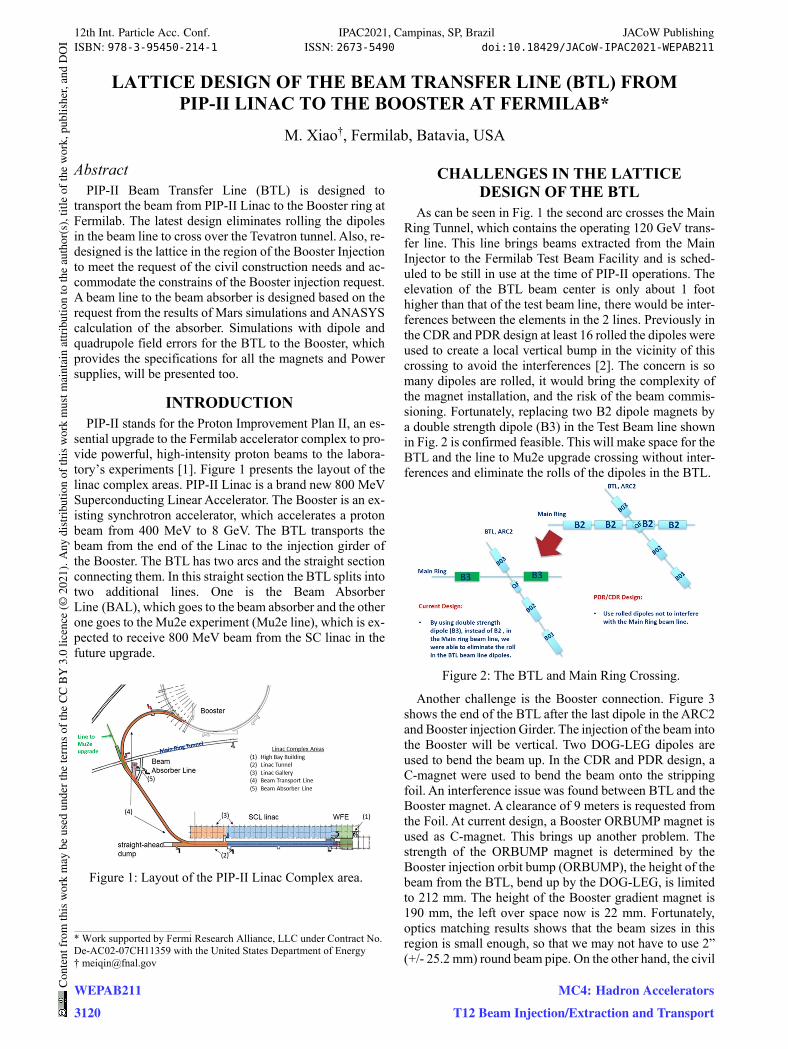
sential upgrade to the Fermilab accelerator complex to pro-vide powerful, high-intensity proton beams to the labora-tory’s experiments [1]. Figure 1 presents the layout of the linac complex areas. PIP-II Linac is a brand new 800 MeV Superconducting Linear Accelerator. The Booster is an ex-isting synchrotron accelerator, which accelerates a proton beam from 400 MeV to 8 GeV. The BTL transports the beam from the end of the Linac to the injection girder of the Booster. The BTL has two arcs and the straight section connecting them. In this straight section the BTL splits into two additional lines. One is the Beam Absorber Line (BAL), which goes to the beam absorber and the other one goes to the Mu2e experiment (Mu2e line), which is ex-pected to receive 800 MeV beam from the SC linac in the future upgrade.
Figure 1: Layout of the PIP-II Linac Complex area.
CHALLENGES IN THE LATTICE DESIGN OF THE BTL
As can be seen in Fig. 1 the second arc crosses the Main Ring Tunnel, which contains the operating 120 GeV trans-fer line. This line brings beams extracted from the Main Injector to the Fermilab Test Beam Facility and is sched-uled to be still in use at the time of PIP-II operations. The elevation of the BTL beam center is only about 1 foot higher than that of the test beam line, there would be inter-ferences between the elements in the 2 lines. Previously in the CDR and PDR design at least 16 rolled the dipoles were used to create a local vertical bump in the vicinity of this crossing to avoid the interferences [2]. The concern is so many dipoles are rolled, it would bring the complexity of the magnet installation, and the risk of the beam commis-sioning. Fortunately, replacing two B2 dipole magnets by a double strength dipole (B3) in the Test Beam line shown in Fig. 2 is confirmed feasible. This will make space for the BTL and the line to Mu2e upgrade crossing without inter-ferences and eliminate the rolls of the dipoles in the BTL.
Figure 2: The BTL and Main Ring Crossing.
Another challenge is the Booster connection. Figure 3 shows the end of the BTL after the last dipole in the ARC2 and Booster injection Girder. The injection of the beam into the Booster will be vertical. Two DOG-LEG dipoles are used to bend the beam up. In the CDR and PDR design, a C-magnet were used to bend the beam onto the stripping foil. An interference issue was found between BTL and the Booster magnet. A clearance of 9 meters is requested from the Foil. At current design, a Booster ORBUMP magnet is used as C-magnet. This brings up another problem. The strength of the ORBUMP magnet is determined by the Booster injection orbit bump (ORBUMP), the height of the beam from the BTL, bend up by the DOG-LEG, is limited to 212 mm. The height of the Booster gradient magnet is 190 mm, the left over space now is 22 mm. Fortunately, optics matching results shows that the beam sizes in this region is small enough, so that we may not have to use 2” (+/- 25.2 mm) round beam pipe. On the other hand, the civil
___________________________________________
* Work supported by Fermi Research Alliance, LLC under Contract No. De-AC02-07CH11359 with the United States Department of Energy † [email protected]
12th Int. Particle Acc. Conf. IPAC2021, Campinas, SP, Brazil JACoW PublishingISBN: 978-3-95450-214-1 ISSN: 2673-5490 doi:10.18429/JACoW-IPAC2021-WEPAB211
WEPAB211Con
tent
from
this
wor
km
aybe
used
unde
rthe
term
sof
the
CC
BY
3.0
licen
ce(©
2021
).A
nydi
stri
butio
nof
this
wor
km
ustm
aint
ain
attr
ibut
ion
toth
eau
thor
(s),
title
ofth
ew
ork,
publ
ishe
r,an
dD
OI
3120
MC4: Hadron Accelerators
T12 Beam Injection/Extraction and Transport
construction strategy in PDR/CDR requires tearing down Booster Tower East Enclosure and removing a section of the Booster and build a BTL service building which con-nects to the rebuilt Booster Tower east, then reinstall the part of the Booster. A big concern is on the impact of the 40 years old Booster machine. A strong request to the civil construction is to keep the Booster untouched. A solution of the BTL optics was found, a Chute – an 8 meters beam pipe will be utilized in the current design for the connection between the BTL and the Booster. Now the civil construc-tion strategy is changed so that the Booster machine and the Booster Enclosure keep unchanged.
Figure 3: The BTL, the Booster connection and injection into the Booster.
The Beam Switch system, which consists of a fast cor-rector and a septum with 3 apertures. In the CDR and PDR design, only one beam switching system is installed in the 4th and 5th cells of the straight section. When the field in the fast corrector is on the beam is deflected from the center orbit and passes through two large aperture quadrupoles before it comes to the septum. When the beam reaches the 3-way septum, it enters into one of two side apertures which magnetic field deflects the beam to the BAL or the Mu2e line. If the fast corrector is off, the beam remains at the vacuum chamber axis and arrives the septum central aperture. There is no magnetic field in this aperture and the beam is continue its direction to the Booster. At current de-sign of the Main Ring Crossing, if the beam for the Mu2e line is deflected from 4th cell with a minimum angle needed to go through the Septum, an interference between a quad in the future Mu2e line and a B3 in the Main Ring BTL can’t be avoided. Therefore, the 7th and 8th straight section FODO cells are reserved for the installation of another identical beam switch system for the Mu2e line, and the Septum magnet now actually only need to be 2-ways.
LATTICE OF THE BTL AND THE BAL The particle loss of the BTL is dominated by Lorentz
stripping, which limited the magnetic field of the dipoles to 2.39 kG for the beam of 800 MeV. The angle difference in the horizontal plane between the linac direction and the Booster injection straight is around 217°. This bending an-gle is produced by 32 identical 2.45 m long (effective length) rectangular dipoles with 2.282 kG field. A FODO lattice is used for the beam transport line. Four achromatic
ARCs, each with 4 FODO cells, connected by a straight section with 8 FODO cells. Phase advances of the FODO cell is 90° in both horizontal and vertical planes. Its period is chosen to keep the dispersion and betafunctions compa-rable to their values in the SC Linac and Booster. Geomet-rical constraints set the cell length to about 11.8 m.
The BAL follows the similar FODO cell structure too. It starts from the end of the Septum in the BTL and consists of five dipole magnets of the same design as used in the arcs. It deflects the beam horizontally to the beam absorber placed so that there would not be any other beam lines at distances smaller than 10 m. Four quadrupoles of the sim-ilar design as used in the arcs are used for beam focusing. We purposely placed the first defocusing quad a bit far away from the Septum, so that the two defocusing quads in the BTL and the BAL won’t interference in the tunnel with the designed bending angle of the switch magnet. This dis-tance is 3 meters. As mentioned, the effective length of the dipole is 2.45 meters, but the physical length of the dipole is 3.2 meters, as its preliminary design shows. It was found that the space left between the dipoles in the design of PDR/CDR is not enough to accommodate the ends for coils of the magnets, the BPMs and correctors etc. In the current design, the separation between dipoles are increased, BPMs and correctors are placed in the lattice. The quads are relocated accordingly, which helps smoothing the beta-functions in the line while keeping the same constrains on the core of the absorber. Five dipoles in the BAL are con-trolled by one power supply, independent of the BTL di-poles. We also requested 4 power supplies for 4 quadru-poles in the BAL, this makes the beta-functions in the line more smoothly and more flexible for the future commis-sioning.
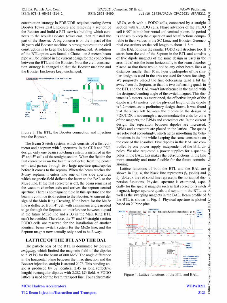
Lattice functions of both the BTL and the BAL are shown in Fig. 4, the black line represents βx (solid) and βy (dotted), the red solid line represents the horizontal dis-persion functions. Physical aperture is examined, espe-cially for the special magnets such as fast corrector (switch magnet), larger aperture quads and septum in the BTL, as well as the sweeping magnets in the BAL. Beam profile of the BTL is shown in Fig. 5. Physical aperture is plotted based on 2” bine pine.
Figure 4: Lattice functions of the BTL and BAL.
12th Int. Particle Acc. Conf. IPAC2021, Campinas, SP, Brazil JACoW PublishingISBN: 978-3-95450-214-1 ISSN: 2673-5490 doi:10.18429/JACoW-IPAC2021-WEPAB211
MC4: Hadron Accelerators
T12 Beam Injection/Extraction and Transport
WEPAB211
3121
Con
tent
from
this
wor
km
aybe
used
unde
rthe
term
sof
the
CC
BY
3.0
licen
ce(©
2021
).A
nydi
stri
butio
nof
this
wor
km
ustm
aint
ain
attr
ibut
ion
toth
eau
thor
(s),
title
ofth
ew
ork,
publ
ishe
r,an
dD
OI
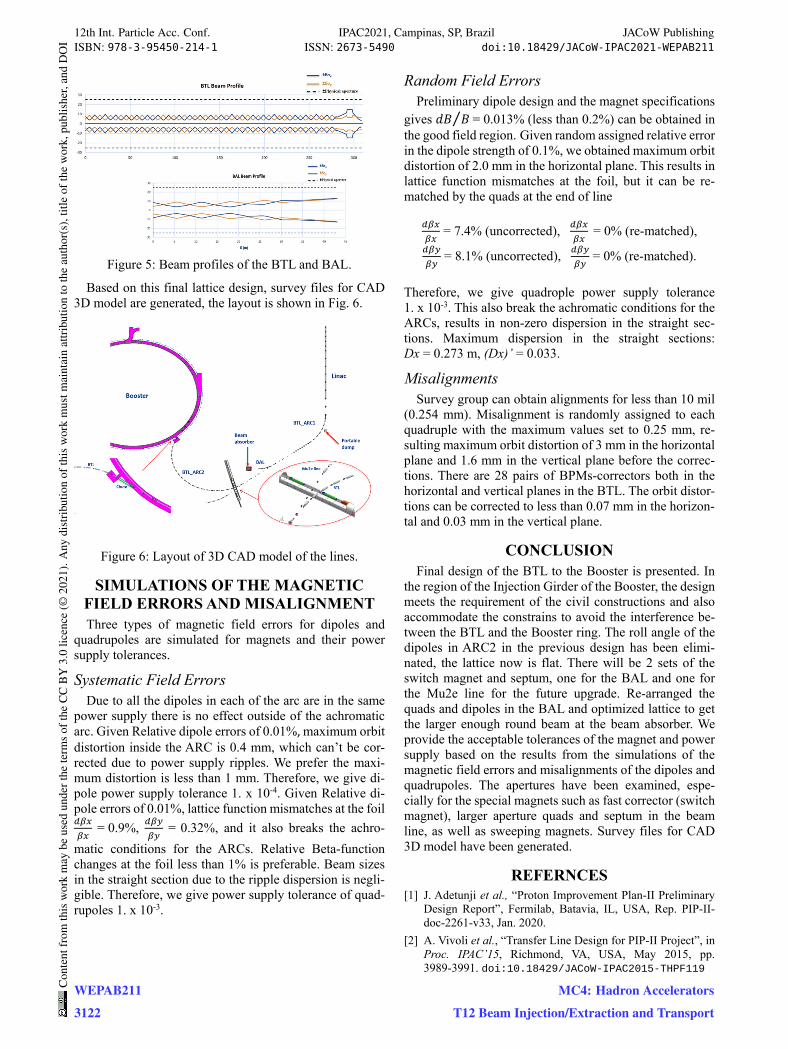
Figure 5: Beam profiles of the BTL and BAL.
Based on this final lattice design, survey files for CAD 3D model are generated, the layout is shown in Fig. 6.
Figure 6: Layout of 3D CAD model of the lines.
SIMULATIONS OF THE MAGNETIC FIELD ERRORS AND MISALIGNMENT Three types of magnetic field errors for dipoles and
quadrupoles are simulated for magnets and their power supply tolerances.
Systematic Field Errors Due to all the dipoles in each of the arc are in the same
power supply there is no effect outside of the achromatic arc. Given Relative dipole errors of 0.01%, maximum orbit distortion inside the ARC is 0.4 mm, which can’t be cor-rected due to power supply ripples. We prefer the maxi-mum distortion is less than 1 mm. Therefore, we give di-pole power supply tolerance 1. x 10-4. Given Relative di-pole errors of 0.01%, lattice function mismatches at the foil = 0.9%, = 0.32%, and it also breaks the achro-matic conditions for the ARCs. Relative Beta-function changes at the foil less than 1% is preferable. Beam sizes in the straight section due to the ripple dispersion is negli-gible. Therefore, we give power supply tolerance of quad-rupoles 1. x 10-3.
Random Field Errors Preliminary dipole design and the magnet specifications
gives 𝑑𝐵 𝐵 = 0.013%⁄ (less than 0.2%) can be obtained in the good field region. Given random assigned relative error in the dipole strength of 0.1%, we obtained maximum orbit distortion of 2.0 mm in the horizontal plane. This results in lattice function mismatches at the foil, but it can be re-matched by the quads at the end of line
= 7.4% (uncorrected), = 0% (re-matched),
= 8.1% (uncorrected), = 0% (re-matched).
Therefore, we give quadrople power supply tolerance 1. x 10-3. This also break the achromatic conditions for the ARCs, results in non-zero dispersion in the straight sec-tions. Maximum dispersion in the straight sections: Dx = 0.273 m, (Dx)’ = 0.033.
Misalignments Survey group can obtain alignments for less than 10 mil
(0.254 mm). Misalignment is randomly assigned to each quadruple with the maximum values set to 0.25 mm, re-sulting maximum orbit distortion of 3 mm in the horizontal plane and 1.6 mm in the vertical plane before the correc-tions. There are 28 pairs of BPMs-correctors both in the horizontal and vertical planes in the BTL. The orbit distor-tions can be corrected to less than 0.07 mm in the horizon-tal and 0.03 mm in the vertical plane.
CONCLUSION Final design of the BTL to the Booster is presented. In
the region of the Injection Girder of the Booster, the design meets the requirement of the civil constructions and also accommodate the constrains to avoid the interference be-tween the BTL and the Booster ring. The roll angle of the dipoles in ARC2 in the previous design has been elimi-nated, the lattice now is flat. There will be 2 sets of the switch magnet and septum, one for the BAL and one for the Mu2e line for the future upgrade. Re-arranged the quads and dipoles in the BAL and optimized lattice to get the larger enough round beam at the beam absorber. We provide the acceptable tolerances of the magnet and power supply based on the results from the simulations of the magnetic field errors and misalignments of the dipoles and quadrupoles. The apertures have been examined, espe-cially for the special magnets such as fast corrector (switch magnet), larger aperture quads and septum in the beam line, as well as sweeping magnets. Survey files for CAD 3D model have been generated.
REFERNCES [1] J. Adetunji et al., “Proton Improvement Plan-II Preliminary
Design Report”, Fermilab, Batavia, IL, USA, Rep. PIP-II-doc-2261-v33, Jan. 2020.
[2] A. Vivoli et al., “Transfer Line Design for PIP-II Project”, in Proc. IPAC’15, Richmond, VA, USA, May 2015, pp. 3989-3991. doi:10.18429/JACoW-IPAC2015-THPF119
12th Int. Particle Acc. Conf. IPAC2021, Campinas, SP, Brazil JACoW PublishingISBN: 978-3-95450-214-1 ISSN: 2673-5490 doi:10.18429/JACoW-IPAC2021-WEPAB211
WEPAB211Con
tent
from
this
wor
km
aybe
used
unde
rthe
term
sof
the
CC
BY
3.0
licen
ce(©
2021
).A
nydi
stri
butio
nof
this
wor
km
ustm
aint
ain
attr
ibut
ion
toth
eau
thor
(s),
title
ofth
ew
ork,
publ
ishe
r,an
dD
OI
3122
MC4: Hadron Accelerators
T12 Beam Injection/Extraction and Transport