Embed Size (px)
Citation preview
Structural Engineering International 4/2009 Structures Worldwide 1
Launching the Vicario Viaduct: Andalucia, SpainJosé M. Simón-Talero, Prof., Civil Eng.; Ramón M. Merino, Civil Eng.; Torroja Ingeniería S.L., Madrid, Spain.
Contact: [email protected]
The final alignment of the motorway defined a 175 m long structure to cross the Vicario gorge. Both slopes of the gorge are too inclined and so it was de-cided to place only one pier on the bot-tom of the gorge. A two-span bridge (87,5 + 87,5 m) was then designed.
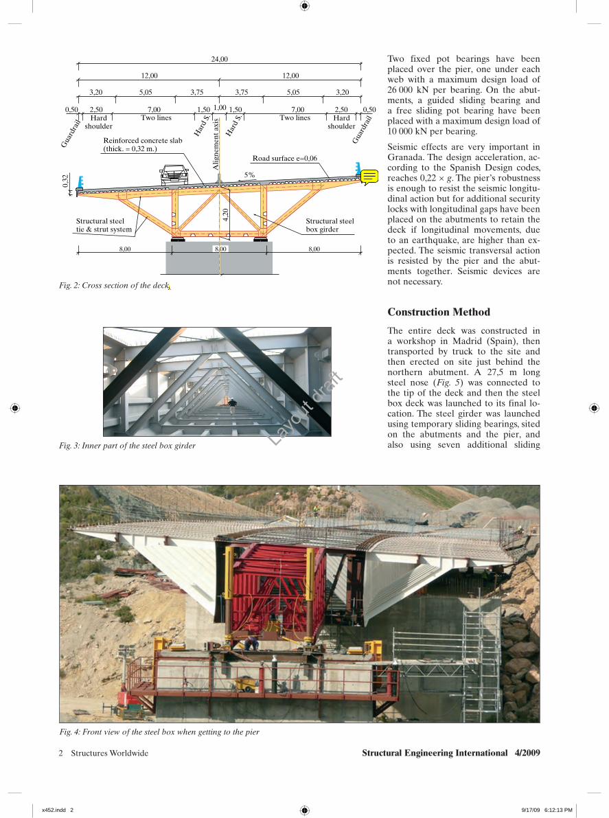
The deck is 24 m wide for a dual carriageway with two lanes in each direction, as shown in Fig. 2. The hori-zontal alignment is a curve, with a ra-dius of 1420 m. The vertical alignment is defined by an ascending gradient of 0,80%. A constant slope of –5% is defined all over the deck in the trans-verse direction.
General Definition
Deck
Keeping in mind the significant seismic action, a steel-concrete composite con-tinuous deck was proposed, to reduce the weight of the deck. The deck is 24 m wide and 175 m long, and divided into two 87,5 m long spans. The cross section depth is 4,52 m (a 4,20 m struc-tural steel box and a 0,32 m reinforced concrete slab).
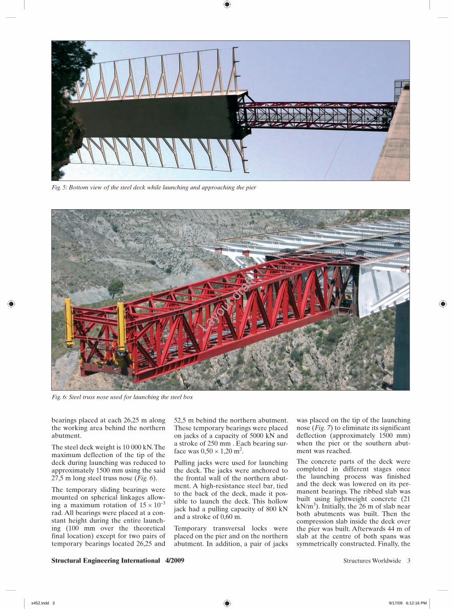
The cross section is a single-cell struc-tural steel box, 8 m wide and 4,20 m deep (Fig. 3). The complete width of 24 m is reached by adding a strut and tie system, each 4,375 m on both sides of the box (Fig. 2).
A reinforced lightweight concrete ribbed slab is placed on the steel box. The connection between steel and con-crete is made using shear connectors. A galvanized steel folded plate has been
used as formwork for the reinforced lightweight concrete slab. Maximum and minimum concrete slab thickness is 0,32 and 0,18 m, respectively.
Important bending moments appear in the deck near the location of the pier and so the bottom plates of the box girder are subject to huge compressive stresses. To prevent buckling of the bottom plates, a cast in situ reinforced concrete slab with 0,50 m thickness is placed over a length of 17,5 m on each side of the pier.
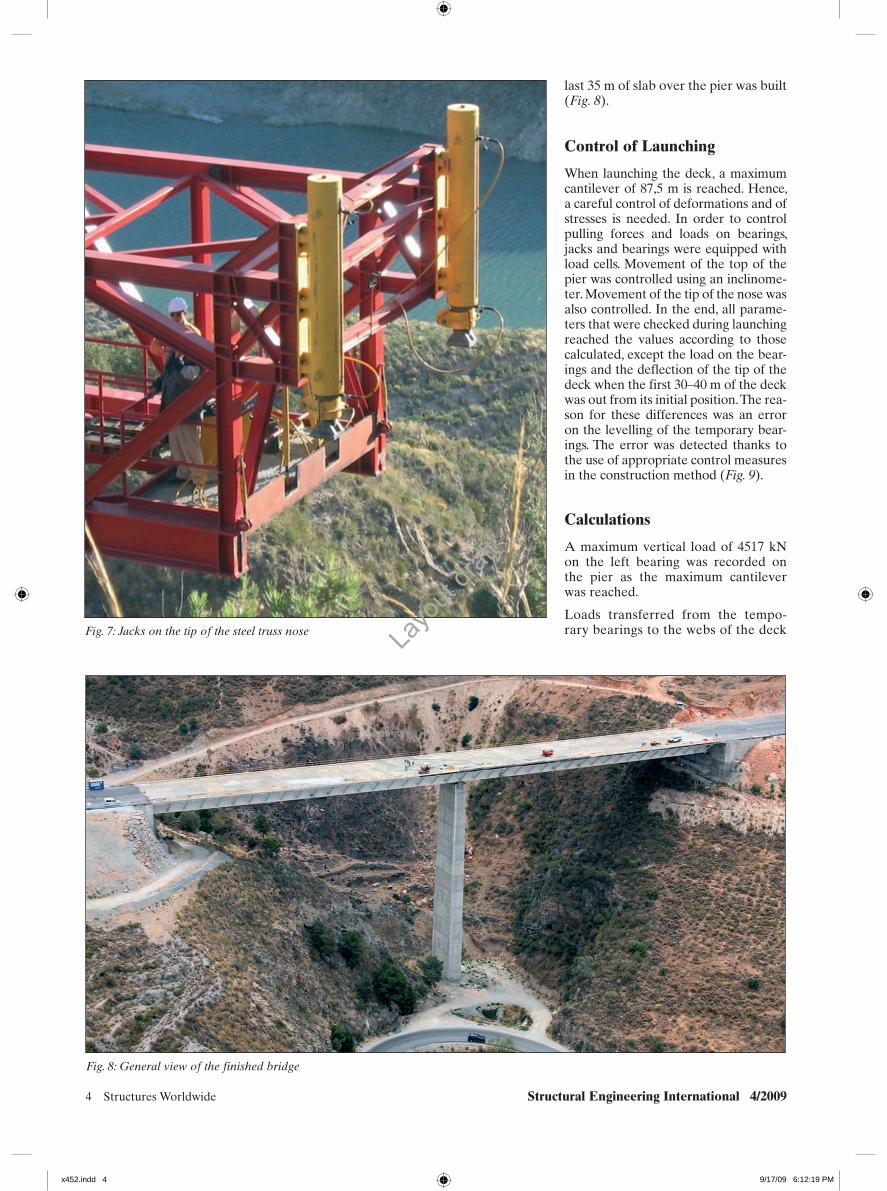
Two different grades of structural steel have been used: S-355 J2G3 for steel plates and S275 J2G3 for steel profiles. Two quality concretes were used: light-weight C37.5 concrete on the ribbed slab (21 kN/m3) and C45 concrete on the compression slab connected to the bottom plate near the piers (Fig. 4).
Pier and Abutments
The abutments are made of reinforced concrete (C30). The foundation is lo-cated directly on the slopes.
The single pier, 63,5 m tall, is made of reinforced concrete (C30). Its foun-dation is built directly on the bottom of the gorge. The pier cross section is hollow, rectangular and thin walled. Its depth is constant at 3,5 m and its width varies linearly with a 1 : 40 gradient. The minimum width, at the top, is 9,0 m. The wall thickness is 0,35 m, con-stant all over the pier. The minimum dimensions of the top of the pier were established because of the construction method for the deck. The pier has been constructed with a climbing formwork.
Summary
The Vicario Viaduct is located in the A-44 motorway, in the South-East part of Spain. It crosses a natural gorge, near the town of Ízbor in the province of Granada.
A single continuous steel-concrete composite deck, 24 m wide and 175 m long, divided in two 87,5 m spans, has been built.
The cross section is a single structural steel box, 8,00 m wide and 4,52 m deep. The total width of 24 m is reached add-ing a strut and tie system each 4,375 m on both sides of the box.
The steel parts of the deck were en-tirely constructed in the workshop and then they were erected on site just be-hind one of the abutments. Finally a 27,5 m long steel nose was connected to launch the deck.
The main problems have been the curved shape of the deck (1420 m radi-us in plan) producing a non symmetric transverse distribution of reactions on each support and the cantilever reach-ing 87,5 m long, producing a maximum deflection of 1500 mm.
Keywords: bridge; launched bridge; composite deck; steel box; cantilever; steel nose; Torroja.
Introduction
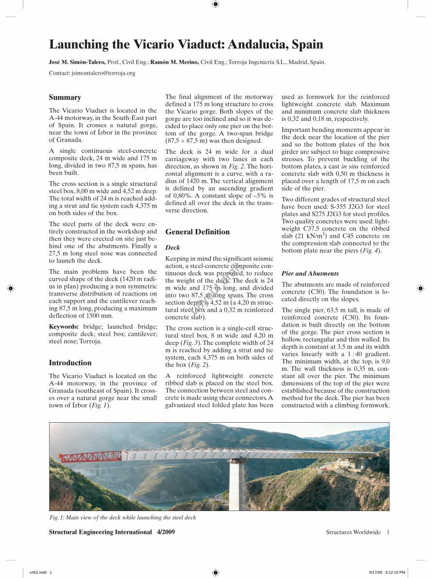
The Vicario Viaduct is located on the A-44 motorway, in the province of Granada (southeast of Spain). It cross-es over a natural gorge near the small town of Ízbor (Fig. 1).
Fig. 1: Main view of the deck while launching the steel deck
x452.indd 1x452.indd 1 9/17/09 6:12:10 PM9/17/09 6:12:10 PM
Layo
ut dra
ft
2 Structures Worldwide Structural Engineering International 4/2009
Two fixed pot bearings have been placed over the pier, one under each web with a maximum design load of 26 000 kN per bearing. On the abut-ments, a guided sliding bearing and a free sliding pot bearing have been placed with a maximum design load of 10 000 kN per bearing.
Seismic effects are very important in Granada. The design acceleration, ac-cording to the Spanish Design codes, reaches 0,22 × g. The pier’s robustness is enough to resist the seismic longitu-dinal action but for additional security locks with longitudinal gaps have been placed on the abutments to retain the deck if longitudinal movements, due to an earthquake, are higher than ex-pected. The seismic transversal action is resisted by the pier and the abut-ments together. Seismic devices are not necessary.
Construction Method
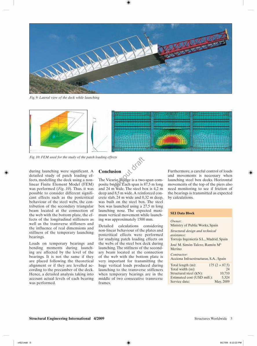
The entire deck was constructed in a workshop in Madrid (Spain), then transported by truck to the site and then erected on site just behind the northern abutment. A 27,5 m long steel nose (Fig. 5) was connected to the tip of the deck and then the steel box deck was launched to its final lo-cation. The steel girder was launched using temporary sliding bearings, sited on the abutments and the pier, and also using seven additional sliding
Fig. 2: Cross section of the deck
8,00 8,008,00
24,00
12,00 12,00
3,20
0,50 0,502,50 2,507,00 7,001,50 1,501,00
3,205,05 5,053,75 3,75
Gua
rdra
il
Gua
rdra
il
Har
d S.
Har
d S.Hard
shoulderHard
shoulderTwo lines Two lines
Reinforced concrete slab(thick. = 0,32 m.)
Road surface e=0,06
Alig
nem
ent a
xis
5%
0,32
Structural steeltie & strut system
Structural steelbox girder
4,20
Fig. 3: Inner part of the steel box girder
Fig. 4: Front view of the steel box when getting to the pier
x452.indd 2x452.indd 2 9/17/09 6:12:13 PM9/17/09 6:12:13 PM
Layo
ut dra
ft
Structural Engineering International 4/2009 Structures Worldwide 3
bearings placed at each 26,25 m along the working area behind the northern abutment.
The steel deck weight is 10 000 kN. The maximum deflection of the tip of the deck during launching was reduced to approximately 1500 mm using the said 27,5 m long steel truss nose (Fig. 6).
The temporary sliding bearings were mounted on spherical linkages allow-ing a maximum rotation of 15 × 10–3 rad. All bearings were placed at a con-stant height during the entire launch-ing (100 mm over the theoretical final location) except for two pairs of temporary bearings located 26,25 and
52,5 m behind the northern abutment. These temporary bearings were placed on jacks of a capacity of 5000 kN and a stroke of 250 mm . Each bearing sur-face was 0,50 × 1,20 m2.
Pulling jacks were used for launching the deck. The jacks were anchored to the frontal wall of the northern abut-ment. A high-resistance steel bar, tied to the back of the deck, made it pos-sible to launch the deck. This hollow jack had a pulling capacity of 800 kN and a stroke of 0,60 m.
Temporary transversal locks were placed on the pier and on the northern abutment. In addition, a pair of jacks
was placed on the tip of the launching nose (Fig. 7) to eliminate its significant deflection (approximately 1500 mm) when the pier or the southern abut-ment was reached.
The concrete parts of the deck were completed in different stages once the launching process was finished and the deck was lowered on its per-manent bearings. The ribbed slab was built using lightweight concrete (21 kN/m3). Initially, the 26 m of slab near both abutments was built. Then the compression slab inside the deck over the pier was built. Afterwards 44 m of slab at the centre of both spans was symmetrically constructed. Finally, the
Fig. 5: Bottom view of the steel deck while launching and approaching the pier
Fig. 6: Steel truss nose used for launching the steel box
x452.indd 3x452.indd 3 9/17/09 6:12:16 PM9/17/09 6:12:16 PM
Layo
ut dra
ft
4 Structures Worldwide Structural Engineering International 4/2009
Fig. 7: Jacks on the tip of the steel truss nose
Fig. 8: General view of the finished bridge
last 35 m of slab over the pier was built (Fig. 8).
Control of Launching
When launching the deck, a maximum cantilever of 87,5 m is reached. Hence, a careful control of deformations and of stresses is needed. In order to control pulling forces and loads on bearings, jacks and bearings were equipped with load cells. Movement of the top of the pier was controlled using an inclinome-ter. Movement of the tip of the nose was also controlled. In the end, all parame-ters that were checked during launching reached the values according to those calculated, except the load on the bear-ings and the deflection of the tip of the deck when the first 30–40 m of the deck was out from its initial position. The rea-son for these differences was an error on the levelling of the temporary bear-ings. The error was detected thanks to the use of appropriate control measures in the construction method (Fig. 9).
Calculations
A maximum vertical load of 4517 kN on the left bearing was recorded on the pier as the maximum cantilever was reached.
Loads transferred from the tempo-rary bearings to the webs of the deck
x452.indd 4x452.indd 4 9/17/09 6:12:19 PM9/17/09 6:12:19 PM
Layo
ut dra
ft
Structural Engineering International 4/2009 Structures Worldwide 5
Fig. 9: Lateral view of the deck while launching
Fig. 10: FEM used for the study of the patch loading effects
during launching were significant. A detailed study of patch loading ef-fects, modelling the deck using a non-linear Finite Element Model (FEM) was performed (Fig. 10). Thus, it was possible to consider different signifi-cant effects such as the postcritical behaviour of the steel webs, the con-tribution of the secondary triangular beam located at the connection of the web with the bottom plate, the ef-fects of the longitudinal stiffeners as well as the transverse stiffeners and the influence of real dimensions and stiffness of the temporary launching bearings.
Loads on temporary bearings and bending moments during launch-ing are affected by the level of the bearings. It is not the same if they are placed following the theoretical alignment or if they are levelled ac-cording to the precamber of the deck. Hence, a detailed analysis taking into account actual levels of each bearing was performed.
Conclusion
The Vicario Bridge is a two-span com-posite bridge. Each span is 87,5 m long and 24 m wide. The steel box is 4,2 m deep and 8,5 m wide. A reinforced con-crete slab, 24 m wide and 0,32 m deep, was built on the steel box. The steel box was launched using a 27,5 m long launching nose. The expected maxi-mum vertical movement while launch-ing was approximately 1500 mm.
Detailed calculations considering non-linear behaviour of the plates and postcritical effects were performed for studying patch loading effects on the webs of the steel box deck during launching. The stiffness of the second-ary beam located at the connection of the web with the bottom plate is very important for transmitting the huge vertical loads produced during launching to the transverse stiffeners when temporary bearings are in the middle of two consecutive transverse frames.
Furthermore, a careful control of loads and movements is necessary when launching steel box decks. Horizontal movements of the top of the piers also need monitoring to see if friction of the bearings is transmitted as expected by calculations.
SEI Data BlockSEI Data Block
Owner:Ministry of Public Works, Spain
Structural design and technical assistance:Torroja Ingeniería S.L., Madrid, Spain
José M. Simón-Talero, Ramón Mª Merino
Contractor:Acciona Infraestructuras, S.A., Spain
Total length (m): 175 (2 × 87.5)Total width (m): 24Structural steel (kN): 10,710Estimated cost (USD mill.): 5,324Service date: May, 2009
x452.indd 5x452.indd 5 9/17/09 6:12:22 PM9/17/09 6:12:22 PM
Layo
ut dra
ft