Embed Size (px)
Citation preview
Draft ES 201 671 V1.1.1 (1999-05)ETSI Standard
Telecommunications security;Lawful Interception (LI);
Handover interface for the lawful interception oftelecommunications traffic
ETSI
Draft ES 201 671 V1.1.1 (1999-05)2
ReferenceDES/SEC-003003 (fh000icp.PDF)
Keywordsdata, handover, interface, security, speech
ETSI
Postal addressF-06921 Sophia Antipolis Cedex - FRANCE
Office address650 Route des Lucioles - Sophia Antipolis
Valbonne - FRANCETel.: +33 4 92 94 42 00 Fax: +33 4 93 65 47 16
Siret N° 348 623 562 00017 - NAF 742 CAssociation à but non lucratif enregistrée à laSous-Préfecture de Grasse (06) N° 7803/88
Individual copies of this ETSI deliverablecan be downloaded from
http://www.etsi.orgIf you find errors in the present document, send your
comment to: [email protected]
Copyright Notification
No part may be reproduced except as authorized by written permission.The copyright and the foregoing restriction extend to reproduction in all media.
© European Telecommunications Standards Institute 1999.All rights reserved.
ETSI
Draft ES 201 671 V1.1.1 (1999-05)3
Contents
Intellectual Property Rights................................................................................................................................8
Foreword ............................................................................................................................................................8
1 Scope........................................................................................................................................................9
2 References................................................................................................................................................9
3 Definitions, symbols and abbreviations .................................................................................................113.1 Definitions ....................................................................................................................................................... 113.2 Abbreviations................................................................................................................................................... 14
4 General requirements .............................................................................................................................164.1 Basic principles for the handover interface...................................................................................................... 164.2 Legal requirements........................................................................................................................................... 164.3 Interfaces and process...................................................................................................................................... 164.4 Example process .............................................................................................................................................. 17
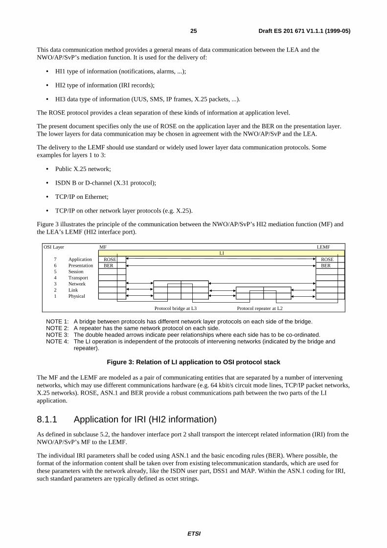
5 Overview of handover interface.............................................................................................................185.1 Handover interface port 1 (HI1) ...................................................................................................................... 195.1.1 Manual interface......................................................................................................................................... 195.1.2 Electronic interface .................................................................................................................................... 195.2 Handover interface port 2 (HI2) ...................................................................................................................... 195.3 Handover interface port 3 (HI3) ...................................................................................................................... 205.3.1 Circuit switched, 64 kbit/s based services .................................................................................................. 205.3.2 User information messages......................................................................................................................... 205.3.3 Packet switched data services..................................................................................................................... 20
6 Specific identifiers for LI.......................................................................................................................206.1 Lawful interception identifier (LIID) ............................................................................................................... 206.2 Call identifier (CID)......................................................................................................................................... 206.2.1 Network identifier (NID)............................................................................................................................ 216.2.2 Call identity number (CIN) ........................................................................................................................ 216.3 CC link identifier (CCLID).............................................................................................................................. 216.4 Correlation between CC and IRI...................................................................................................................... 216.5 Usage of Identifiers.......................................................................................................................................... 22
7 HI1: Interface port for administrative information ................................................................................237.1 Information for the activation of lawful interception ....................................................................................... 237.2 LI notifications towards the LEMF.................................................................................................................. 24
8 HI2: Interface port for intercept related information .............................................................................248.1 Data transmission link, protocol ...................................................................................................................... 248.1.1 Application for IRI (HI2 information)........................................................................................................ 258.1.2 Application for LI notifications (HI1) and CC (HI3) ................................................................................. 268.2 Definition of intercept related information ...................................................................................................... 268.3 Types of IRI records ........................................................................................................................................ 268.4 Structure of IRI records ................................................................................................................................... 278.4.1 Control information for HI2 ....................................................................................................................... 278.4.2 Basic call information ................................................................................................................................ 278.4.3 Information on supplementary services, related to a call in progress ......................................................... 288.4.4 Information on non call related supplementary services ............................................................................ 288.5 Selection of parameters for IRI records ........................................................................................................... 298.6 Coding of parameters in IRI records................................................................................................................ 318.7 Information content of the IRI record types..................................................................................................... 31
9 HI3: Interface port for content of communication .................................................................................319.1 Delivery of circuit switched content of communication................................................................................... 329.2 Delivery of packetized content of communication (general)............................................................................ 339.3 Control information for HI3............................................................................................................................. 34
ETSI
Draft ES 201 671 V1.1.1 (1999-05)4
9.3.1 Circuit switched content of communication ............................................................................................... 349.3.2 Packetized content of communication ........................................................................................................ 35
10 LI procedures for circuit switched supplementary services...................................................................3510.1 General............................................................................................................................................................. 3510.2 CC link Impact................................................................................................................................................. 3610.3 IRI Impact, General Principle for Sending IRI records.................................................................................... 3610.4 Multi party calls – general principles, options A, B......................................................................................... 3710.4.1 CC links for active and non-active calls (option A) ................................................................................... 3710.4.2 Reuse of CC links for active calls (option B) ............................................................................................. 3810.5 Subscriber Controlled Input (SCI): Activation / Deactivation / Interrogation of Services............................... 39
11 Performance & quality ...........................................................................................................................4111.1 Timing.............................................................................................................................................................. 4111.2 Quality ............................................................................................................................................................. 41
12 Exception handling ................................................................................................................................4112.1 Failure of CC links........................................................................................................................................... 4112.2 Failure of ROSE protocol stack ....................................................................................................................... 4112.3 Fault reporting.................................................................................................................................................. 4212.4 Handling of Unrecognized Fields and Parameters ........................................................................................... 42
13 Security aspects......................................................................................................................................4213.1 Security requirements at the interface port HI1 ............................................................................................... 4213.2 Security requirements at the interface port HI2 ............................................................................................... 4213.3 Security requirements at the interface port HI3 ............................................................................................... 4313.3.1 LI access verification.................................................................................................................................. 4313.3.2 Access protection ....................................................................................................................................... 4313.3.3 Authentication ............................................................................................................................................ 43
14 Quantitative aspects ...............................................................................................................................43
Annex A (normative): Operation for sending of data across the HI interface ..............................44
A.1 Syntax definitions ..................................................................................................................................44
A.2 Object tree..............................................................................................................................................45
A.3 HI management operation ......................................................................................................................46
A.4 LI management notification ...................................................................................................................47
A.5 Intercept related information (HI2)........................................................................................................48
A.6 User data packet transfer (HI3 interface)...............................................................................................55
A.7 TETRA data transfer (HI3 interface).....................................................................................................56
A.8 GPRS data transfer (HI3 interface)........................................................................................................57
A.9 Definition of the UUS1 content associated to the CC link ....................................................................57
Annex B (normative): Detailed procedures for supplementary services (circuit switched).........58
B.1 Advice of Charge Services (AOC).........................................................................................................58
B.2 Call Waiting ...........................................................................................................................................58B.2.1 Call Waiting at target: CC links ....................................................................................................................... 58B.2.2 Call Waiting: IRI records................................................................................................................................. 58B.2.2.1 Target is served user................................................................................................................................... 58B.2.2.2 Other party is served user........................................................................................................................... 58
B.3 Call Hold/Retrieve .................................................................................................................................58B.3.1 CC links for active and non-active calls (option A) ........................................................................................ 58B.3.2 Reuse of CC links for active calls (option B)................................................................................................... 59B.3.3 IRI records ....................................................................................................................................................... 59B.3.3.1 Invocation of Call Hold or Retrieve by target: ........................................................................................... 59
ETSI
Draft ES 201 671 V1.1.1 (1999-05)5
B.3.3.2 Invocation of Hold or Retrieve by other parties: ........................................................................................ 59
B.4 Explicit Call Transfer.............................................................................................................................59B.4.1 Explicit Call Transfer, CC link ........................................................................................................................ 59B.4.2 Explicit Call Transfer, IRI records................................................................................................................... 59
B.5 Calling Line Identification Presentation (IRI Records) .........................................................................59B.5.1 Call originated by target (target is served user) ............................................................................................... 59B.5.2 Call terminated at target (other party is served user) ....................................................................................... 60
B.6 Calling Line Identification Restriction (CLIR)......................................................................................60
B.7 Connected Line Identification Presentation (COLP).............................................................................60B.7.1 Call terminated at target (target is served user)................................................................................................ 60B.7.2 Call originated by target (other party is served user) ....................................................................................... 60
B.8 Connected Line Identification restriction (COLR) ................................................................................60
B.9 Closed User Group (CUG).....................................................................................................................60
B.10 Completion of Call to Busy Subscriber (CCBS) ...................................................................................60
B.11 Conference Call, Add-On (CONF) ........................................................................................................61B.11.1 Conference Calls, Add On: CC links ............................................................................................................... 61B.11.2 Conference Calls: IRI records.......................................................................................................................... 61
B.12 Three Party Service (Conference)..........................................................................................................61B.12.1 CC links ........................................................................................................................................................... 61B.12.2 Three Party Service, IRI Records .................................................................................................................... 61
B.13 Meet-Me Conference (MMC)................................................................................................................61
B.14 Direct Dialing In (DDI)..........................................................................................................................61
B.15 Multiple Subscriber Number (MSN) .....................................................................................................62
B.16 Diversion Services (DIV).......................................................................................................................62B.16.1 Call Diversion by Target.................................................................................................................................. 62B.16.1.1 Call Diversion by Target, CC links ............................................................................................................ 62B.16.1.2 Call Diversion by Target, IRI records ........................................................................................................ 62B.16.2 Forwarded Call Terminated at Target .............................................................................................................. 63B.16.3 Call from Target Forwarded ............................................................................................................................ 63
B.17 Variants of call diversion services .........................................................................................................63
B.18 Freephone (FPH)....................................................................................................................................63
B.19 Malicious Call Identification (MCID) ...................................................................................................63
B.20 Subaddressing (SUB).............................................................................................................................63
B.21 Terminal Portability (TP).......................................................................................................................63B.21.1 CC links ........................................................................................................................................................... 63B.21.2 IRI records ....................................................................................................................................................... 63B.21.2.1 Invocation of Terminal Portability by target .............................................................................................. 63B.21.2.2 Invocation of Terminal Portability by other parties.................................................................................... 64
ETSI
Draft ES 201 671 V1.1.1 (1999-05)6
B.22 User-to-User Signalling (UUS)..............................................................................................................64
B.23 Abbreviated Address (AA) ....................................................................................................................64
B.24 Fixed Destination Call (FDC)................................................................................................................64
B.25 Alarm Call (AC) / Wake Up Service (WUS).........................................................................................64
B.26 Incoming Call Barring (ICB) .................................................................................................................64
B.27 Outgoing Call Barring (OCB)................................................................................................................64
B.28 Completion of Calls on No Reply (CCNR) ...........................................................................................64
B.29 Reverse Charging ...................................................................................................................................65
B.30 Line Hunting ..........................................................................................................................................65
B.31 Message Wait Indication (MWI) ...........................................................................................................65
B.32 Name display..........................................................................................................................................65
B.33 Tones, Announcements..........................................................................................................................65
Annex C (normative): Application Service Element for the Handover Interface (ASE_HI) .......66
C.1 Architecture............................................................................................................................................66
C.2 ASE_HI procedures ...............................................................................................................................66C.2.1 Sending part ..................................................................................................................................................... 66C.2.2 Receiving part .................................................................................................................................................. 67C.2.3 Data link management...................................................................................................................................... 68C.2.3.1 Data link establishment .............................................................................................................................. 68C.2.3.2 Data link release......................................................................................................................................... 69
Annex D (informative): Overview description for CC link and IRI delivery - state model............70
Annex E (informative): Message Sequence Diagrams, IRI content ..................................................73
E.1 General remarks .....................................................................................................................................73
E.2 Remarks to tables ...................................................................................................................................74
E.3 Remarks to scenarios..............................................................................................................................74
E.4 Originating target, basic call ..................................................................................................................75E.4.1 Initial LI procedures......................................................................................................................................... 75E.4.2 Set up of an additional call leg......................................................................................................................... 77E.4.3 IRI-CONTINUE records (general) .................................................................................................................. 77E.4.4 Answer by other party...................................................................................................................................... 77E.4.5 Call release (originating or terminating target) ................................................................................................ 78
E.5 Terminating target, basic call.................................................................................................................80E.5.1 Initial LI procedure .......................................................................................................................................... 80E.5.2 Answer by target .............................................................................................................................................. 81E.5.3 Call release....................................................................................................................................................... 82
E.6 Originating target call, invocation of LI relevant services.....................................................................82E.6.1 Call forwarded by called party......................................................................................................................... 82
E.7 Terminating target call, invocation of LI relevant services ...................................................................84E.7.1 Terminating call at target is a forwarded call................................................................................................... 84E.7.2 Call forwarded by target .................................................................................................................................. 84E.7.3 Target invokes Call Waiting (CW) .................................................................................................................. 87
E.8 Target actions during a call in progress .................................................................................................87E.8.1 Call HOLD by target........................................................................................................................................ 88E.8.2 Call RETRIEVE by target ............................................................................................................................... 88
ETSI
Draft ES 201 671 V1.1.1 (1999-05)7
E.9 Three Party Service (3PTY)...................................................................................................................89E.9.1 Target establishes Three Party Conference (3PTY)......................................................................................... 89E.9.2 Target: Private communication with Active-Idle party .................................................................................... 90E.9.3 Target: Private communication with Active-Held party................................................................................... 90E.9.4 Release of 3 PTY conference by Active-Held party ........................................................................................ 91E.9.5 Release of 3 PTY conference by Active-Idle party.......................................................................................... 91
E.10 Add on conference (CONF)...................................................................................................................91E.10.1 Mapping of PartyId / ConferenceId to call identifiers ..................................................................................... 91E.10.2 Beginning a conference from the Idle call state ............................................................................................... 92E.10.3 Beginning a conference from the Active call state........................................................................................... 92E.10.4 Adding a remote user ....................................................................................................................................... 93E.10.5 Splitting a remote user ..................................................................................................................................... 94E.10.6 Further actions during a conference................................................................................................................. 95E.10.7 Target clears the conference ............................................................................................................................ 96E.10.8 Option B (CC link only for active call)............................................................................................................ 97E.10.9 Add on conference using other protocols......................................................................................................... 97
E.11 Target exchange receives notification related to other party.................................................................97
E.12 Service Activation (not call related) ......................................................................................................98
E.13 Service activation / invocation during a call..........................................................................................98E.13.1 ISDN accesses.................................................................................................................................................. 98E.13.2 Analogue accesses ........................................................................................................................................... 98
E.14 Unsuccessful calls from target (originating), IRI-BEGIN record sent...................................................99
E.15 Unsuccessful calls from / to target, IRI-BEGIN record not sent .........................................................100
Annex F (informative): Use of subaddress to carry correlation information ................................101
F.1 Introduction..........................................................................................................................................101
F.2 Subaddress options...............................................................................................................................101
F.3 Subaddress coding................................................................................................................................101F.3.1 BCD Values ................................................................................................................................................... 101F.3.2 Field order and layout .................................................................................................................................... 102
F.4 Field coding..........................................................................................................................................103F.4.1 Direction ........................................................................................................................................................ 103F.4.2 Basic Service ................................................................................................................................................. 103
F.5 Length of fields ....................................................................................................................................103
Bibliography...................................................................................................................................................104
History............................................................................................................................................................105
ETSI
Draft ES 201 671 V1.1.1 (1999-05)8
Intellectual Property RightsIPRs essential or potentially essential to the present document may have been declared to ETSI. The informationpertaining to these essential IPRs, if any, is publicly available for ETSI members and non-members, and can be foundin SR 000 314: "Intellectual Property Rights (IPRs); Essential, or potentially Essential, IPRs notified to ETSI in respectof ETSI standards", which is available free of charge from the ETSI Secretariat. Latest updates are available on theETSI Web server (http://www.etsi.org/ipr).
Pursuant to the ETSI IPR Policy, no investigation, including IPR searches, has been carried out by ETSI. No guaranteecan be given as to the existence of other IPRs not referenced in SR 000 314 (or the updates on the ETSI Web server)which are, or may be, or may become, essential to the present document.
ForewordThis ETSI Standard (ES) has been produced by ETSI Technical Committee Security (SEC), and is now submitted forthe ETSI standards Membership Approval Procedure.
ETSI
Draft ES 201 671 V1.1.1 (1999-05)9
1 ScopeThe present document is step 3 of a three step approach to describe a generic handover interface for the provision oflawful interception from a Network Operator, an Access Provider or a Service Provider (NWO/AP/SvP) to the LawEnforcement Agencies (LEAs). The provision of lawful interception is a requirement of national law, which is usuallymandatory for the operation of any telecommunication service. The aim of the present document is also to fulfil the userrequirements for a future mutual assistance between the LEAs of different countries.
Interworking with other countries than those following the present document is for further study.
Step 1 contains the requirements for lawful interception from a users (LEAs) point of view and is published asETR 331 [1].
The derived network functions and the general architecture (or functional model) is described in the step 2 document,ES 201 158 [2].
The present document specifies the generic flow of information as well as the procedures and information elements,which are applicable to any future telecommunication network or service.
The standard specifies in detail network/service specific protocols relating to the provision of lawful interception at thehandover interface, for the following networks/services:
• speech;
• circuit and packet switched data;
• UMTS and similar services.
NOTE: As there are several types of new networks and/or services currently being developed, the presentdocument will subsequently be expanded as soon as the relevant standards will be available as stabledrafts. The revisions of the present document, containing these amendments in additional sections, will bepublished.
Version 1.1.1 will be limited to 64 kbit/s for circuit switched content of communication and certain packetized services.
Where applicable, the present document bases on other ETSI standards or ITU-T Recommendations in the area oftelecommunication services. The reader should be familiar with the referenced standards/recommendations, includingthe ITU Recommendations, which are endorsed by many of the referenced ETSI standards.
2 ReferencesThe following documents contain provisions which, through reference in this text, constitute provisions of the presentdocument.
• References are either specific (identified by date of publication, edition number, version number, etc.) ornon-specific.
• For a specific reference, subsequent revisions do not apply.
• For a non-specific reference, the latest version applies.
• A non-specific reference to an ETS shall also be taken to refer to later versions published as an EN with the samenumber.
[1] ETR 331: "Security Techniques Advisory Group (STAG); Definition of user requirements forlawful interception of telecommunications; Requirements of the law enforcement agencies".
[2] ES 201 158: "Telecommunications security; Lawful Interception (LI); Requirements for networkfunctions".
ETSI
Draft ES 201 671 V1.1.1 (1999-05)10
[3] ETR 330: "Security Techniques Advisory Group (STAG); A guide to legislative and regulatoryenvironment".
[4] ITU-T Recommendation X.25: "Interface between Data Terminal Equipment (DTE) and DataCircuit-terminating Equipment (DCE) for terminals operating in the packet mode and connected topublic data networks by dedicated circuit".
[5] EN 300 356-1 to 20: "Integrated Services Digital Network (ISDN); Signalling System No.7; ISDNUser Part (ISUP) version 3 for the international interface; Parts 1 to 20".
[6] EN 300 403-1 (V1.2): "Integrated Services Digital Network (ISDN); Digital Subscriber SignallingSystem No. one (DSS1) protocol; Signalling network layer for circuit-mode basic call control;Part 1: Protocol specification [ITU-T Recommendation Q.931 (1993), modified]".
[7] Void.
[8] Void.
[9] Void.
[10] EN 300 061-1: "Integrated Services Digital Network (ISDN); Subaddressing (SUB) supplementaryservice; Digital Subscriber Signalling System No. one (DSS1) protocol; Part 1: Protocolspecification".
[11] Void.
[12] Void.
[13] Void.
[14] EN 300 097-1 including Amendment 1: "Integrated Services Digital Network (ISDN); ConnectedLine Identification Presentation (COLP) supplementary service; Digital Subscriber SignallingSystem No. one (DSS1) protocol; Part 1: Protocol specification".
[15] EN 300 098-1: "Integrated Services Digital Network (ISDN); Connected Line IdentificationRestriction (COLR) supplementary service; Digital Subscriber Signalling System No. one (DSS1)protocol; Part 1: Protocol specification".
[16] EN 300 130-1: "Integrated Services Digital Network (ISDN); Malicious Call Identification(MCID) supplementary service; Digital Subscriber Signalling System No. one (DSS1) protocol;Part 1: Protocol specification".
[17] EN 300 138-1 including Amendment 1: "Integrated Services Digital Network (ISDN); Closed UserGroup (CUG) supplementary service; Digital Subscriber Signalling System No. one (DSS1)protocol; Part 1: Protocol specification".
[18] Void.
[19] EN 300 185-1: "Integrated Services Digital Network (ISDN); Conference call, add-on (CONF)supplementary service; Digital Subscriber Signalling System No. one (DSS1) protocol; Part 1:Protocol specification".
[20] ETS 300 188-1: "Integrated Services Digital Network (ISDN); Three-Party (3PTY) supplementaryservice; Digital Subscriber Signalling System No. one (DSS1) protocol; Part 1: Protocolspecification".
[21] EN 300 207-1 (V1.2): "Integrated Services Digital Network (ISDN); Diversion supplementaryservices; Digital Subscriber Signalling System No. one (DSS1) protocol; Part 1: Protocolspecification".
[22] Void.
[23] EN 300 286-1: "Integrated Services Digital Network (ISDN); User-to-User Signalling (UUS)supplementary service; Digital Subscriber Signalling System No. one (DSS1) protocol; Part 1:Protocol specification".
ETSI
Draft ES 201 671 V1.1.1 (1999-05)11
[24] Void.
[25] EN 300 369-1 (V1.2): "Integrated Services Digital Network (ISDN); Explicit Call Transfer (ECT)supplementary service; Digital Subscriber Signalling System No. one (DSS1) protocol; Part 1:Protocol specification".
[26] Void.
[27] Void.
[28] Void.
[29] EN 300 196-1 (V1.2): "Integrated Services Digital Network (ISDN); Generic functional protocolfor the support of supplementary services; Digital Subscriber Signalling System No. one (DSS1)protocol; Part 1: Protocol specification".
[30] Void.
[31] ITU-T Recommendation Q.850: "Usage of cause and location in the Digital Subscriber SignallingSystem No. 1 and the Signalling System No. 7 ISDN User Part".
[32] GSM 09.02: "Digital cellular telecommunications system (Phase 2+); Mobile Application Part(MAP) specification".
[33] ITU-T Recommendation X.208: "Specification of Abstract Syntax Notation One (ASN.1)".
[34] ITU-T Recommendation X.209: "Specification of basic encoding rules for Abstract SyntaxNotation One (ASN.1)".
[35] ITU-T Recommendation X.880: "Information technology – Remote Operations: Concepts, modeland notation".
[36] ITU-T Recommendation X.881: "Information technology – Remote Operations: OSI realizations –Remote Operations Service Element (ROSE) service definition".
[37] ITU-T Recommendation X.882: "Information technology – Remote Operations: OSI realizations –Remote Operations Service Element (ROSE) protocol specification".
[38] Void.
[39] EN 300 122-1: "Integrated Services Digital Network (ISDN); Generic keypad protocol for thesupport of supplementary services; Digital Subscriber Signalling System No. one (DSS1) protocol;Part 1: Protocol specification".
[40] ETS 300 392-1: "Terrestrial Trunked Radio (TETRA); Voice plus Data (V+D); Part 1: Generalnetwork design".
3 Definitions, symbols and abbreviations
3.1 DefinitionsFor the purposes of the present document, the terms and definitions given in [1] and [2] apply.
They are reproduced in the list below as required, and defined further as necessary:
access provider: access provider provides a user of some network with access from the user’s terminal to that network.
NOTE 1: This definition applies specifically for the present document. In a particular case, the access provider andnetwork operator may be a common commercial entity.
NOTE 2: The definitions from ETR 331 have been expanded to include reference to an access provider, whereappropriate.
ETSI
Draft ES 201 671 V1.1.1 (1999-05)12
activation/deactivation: procedures for activation, which is the operation of bringing the service into the "ready forinvocation" state, and deactivation, which is the complementary action, are described in this clause. For some servicesthere may be a specific user procedure to allow activation and deactivation as necessary, whilst for others the service ispermanently activated on provision and thus no procedure is provided (see [37]).
(to) buffer: temporary storing of information in case the necessary telecommunication connection to transportinformation to the LEMF is temporarily unavailable.
call: any temporarily switched connection capable of transferring information between two or more users of atelecommunications system. In this context a user may be a person or a machine.
call identifier: see definition in clause 6.
call identity number: see definition in clause 6.
CC link: CC link consists of one or more 64 kbit/s channels, established simultaneously, between a mediation functionand a LEMF; it is used for transmission of the content of communication.
CC link identifier: s ee definition in clause 6.
content of communication: information exchanged between two or more users of a telecommunications service,excluding intercept related information. This includes information which may, as part of some telecommunicationsservice, be stored by one user for subsequent retrieval by another.
handover interface: physical and logical interface across which the interception measures are requested from networkoperator / access provider / service provider, and the results of interception are delivered from a network operator /access provider / service provider to a law enforcement monitoring facility.
identity: technical label which may represent the origin or destination of any telecommunications traffic, as a ruleclearly identified by a physical telecommunications identity number (such as a telephone number) or the logical orvirtual telecommunications identity number (such as a personal number) which the subscriber can assign to a physicalaccess on a case-by-case basis.
interception: action (based on the law), performed by an network operator / access provider / service provider, ofmaking available certain information and providing that information to a law enforcement monitoring facility.
NOTE 3: In the present document the term interception is not used to describe the action of observingcommunications by a law enforcement agency.
interception configuration information: information related to the configuration of interception.
Interception interface: physical and logical locations within the network operator’s / access provider’s / serviceprovider’s telecommunications facilities where access to the content of communication and intercept related informationis provided. The interception interface is not necessarily a single, fixed point.
interception measure: technical measure which facilitates the interception of telecommunications traffic pursuant to therelevant national laws and regulations.
intercept related information: collection of information or data associated with telecommunication services involvingthe target identity, specifically call associated information or data (e.g. unsuccessful call attempts), service associatedinformation or data (e.g. service profile management by subscriber) and location information.
interception subject: person or persons, specified in a lawful authorization, whose telecommunications are to beintercepted.
internal intercepting function: point within a network or network element at which the content of communication andthe intercept related information are made available.
internal network interface: network’s internal interface between the Internal Intercepting Function and a mediationdevice.
invocation and operation: describes the action and conditions under which the service is brought into operation; in thecase of a lawful interception this may only be on a particular call. It should be noted that when lawful interception isactivated, it shall be invoked on all calls (Invocation takes place either subsequent to or simultaneously with activation.).Operation is the procedure which occurs once a service has been invoked.
ETSI
Draft ES 201 671 V1.1.1 (1999-05)13
NOTE 4: The definition is based on [37], but has been adapted for the special application of lawful interception,instead of supplementary services.
law enforcement agency: organization authorized by a lawful authorization based on a national law to requestinterception measures and to receive the results of telecommunications interceptions.
law enforcement monitoring facility: law enforcement facility designated as the transmission destination for the resultsof interception relating to a particular interception subject.
lawful authorization: permission granted to a LEA under certain conditions to intercept specified telecommunicationsand requiring co-operation from a network operator / access provider / service provider. Typically this refers to awarrant or order issued by a lawfully authorized body.
lawful interception: see interception.
lawful interception identifier: see definition in clause 6.
location information: information relating to the geographic, physical or logical location of an identity relating to aninterception subject.
mediation device: equipment, which realizes the mediation function.
mediation function: mechanism which passes information between a network operator, an access provider or serviceprovider and a handover interface, and information between the internal network interface and the handover interface.
network element: component of the network structure, such as a local exchange, higher order switch or service controlprocessor.
network element identifier: see definition in clause 6.
network identifier: see definition in clause 6.
network operator: operator of a public telecommunications infrastructure which permits the conveyance of signalsbetween defined network termination points by wire, by microwave, by optical means or by other electromagneticmeans.
quality of service: quality specification of a telecommunications channel, system, virtual channel, computer-telecommunications session, etc. Quality of service may be measured, for example, in terms of signal-to-noise ratio, biterror rate, message throughput rate or call blocking probability.
reliability: probability that a system or service will perform in a satisfactory manner for a given period of time whenused under specific operating conditions.
result of interception: information relating to a target service, including the content of communication and interceptrelated information, which is passed by a network operator, an access provider or a service provider to a lawenforcement agency. Intercept related information shall be provided whether or not call activity is taking place.
service information: information used by the telecommunications infrastructure in the establishment and operation of anetwork related service or services. The information may be established by a network operator, an access provider, aservice provider or a network user.
service provider: natural or legal person providing one or more public telecommunications services whose provisionconsists wholly or partly in the transmission and routing of signals on a telecommunications network. A service providerneeds not necessarily run his own network.
target identity: technical identity (e.g. the interception’s subject directory number), which uniquely identifies a target ofinterception. One target may have one or several target identities.
target service: telecommunications service associated with an interception subject and usually specified in a lawfulauthorization for interception.
NOTE 5: There may be more than one target service associated with a single interception subject.
telecommunications: any transfer of signs, signals, writing images, sounds, data or intelligence of any naturetransmitted in whole or in part by a wire, radio, electromagnetic, photoelectronic or photo-optical system.

ETSI
Draft ES 201 671 V1.1.1 (1999-05)14
3.2 AbbreviationsFor the purposes of the present document, the following abbreviations apply:
3PTY Three-Party ServiceAA Abbreviated AddressAC Alarm CallACM Address Complete MessageAOC Advice of Charge ServiceAP Access ProviderASN.1 Abstract Syntax Notation, Version 1ASE Application Service ElementATM Asynchronous Transfer ModeBA DSS1 Basic AccessBC Bearer CapabilityBER Basic Encoding RulesBS Basic ServiceCC Content of CommunicationCCBS Completion of Calls to Busy SubscriberCCNR Completion of Calls on No ReplyCD Call DeflectionCF Call ForwardingCFB Call Forwarding on BusyCFNR Call Forwarding on No ReplyCFU Call Forwarding UnconditionalCH Call HoldCCLID CC Link IdentifierCID Call IdentifierCIN Call Identity NumberCLI Calling Line Identity (Calling Party Number)CLIP Calling Line Identification PresentationCLIR Calling Line Identification RestrictionCOL Connected Line Identity (Connected Number)COLP Connected Line Identification PresentationCOLR Connected Line Identification RestrictionCONF Conference Call, Add-onCPG Call Progress MessageCUG Closed User GroupCW Call WaitingDDI Direct Dialing InDIV Call Diversion ServicesDN Directory NumberDSS1 Digital Subscriber Signalling system No.1DTMF Dual Tone Multi-FrequencyECT Explicit Call TransferFB Fallback ProcedureFDC Fixed Destination CallFPH FreephoneGPRS Global Packet radio ServiceGSM Global System for Mobile communicationsHI Handover InterfaceHI1 Handover Interface Port 1 (for Administrative Information)HI2 Handover Interface Port 2 (for Intercept Related Information)HI3 Handover Interface Port 3 (for Content of Communication)HLC High Layer CompatibilityHOLD Call Hold ServiceIA5 International Alphabet No. 5IAM Initial Address MessageIAP Interception Access PointICB Incoming Call Barring

ETSI
Draft ES 201 671 V1.1.1 (1999-05)15
ICC Interception Control CentreICI Interception Configuration InformationIE Information ElementIIF Internal Intercepting FunctionIMEI International Mobile station Equipment IdentityIMSI International Mobile Subscriber IdentityIN Intelligent NetworkINI Internal network interfaceIP Internet ProtocolIRI Intercept Related InformationISDN Integrated services digital networkISUP ISDN user partLEA Law Enforcement AgencyLEMF Law Enforcement Monitoring FacilityLI Lawful InterceptionLIID Lawful Interception IdentifierLLC Lower layer compatibilityLSB Least significant bitMAP Mobile Application PartMCID Malicious Call IdentificationMF Mediation FunctionMMC Meet-me ConferenceMSB Most significant bitMSN Multiple Subscriber NumberNDUB Network Determined User BusyNEID Network Element IdentifierNID Network IdentifierNWO Network OperatorOA&M Operation, Administration & MaintenanceOCB Outgoing Call BarringPLMN Public land mobile networkPR Partial ReroutingPRA ISDN Primary Rate AccessPSPDN Packet switched public data networkPSTN Public Switched Telephone NetworkROSE Remote Operation Service ElementRx Receive directionSCI Subscriber Controlled InputSCF IN Signalling Control FunctionSMS Short Message ServiceSS Supplementary ServiceSS No.7 Common Channel Signalling System ITU(T) No. 7SSF IN Signalling Switching FunctionSTC Sub-Technical CommitteeSUB Subaddressing Supplementary ServiceSvP Service ProviderTCP Transmission Control ProtocolTE Target ExchangeTETRA Trans European Trunked RadioTI Target identityTMR Transmission Medium RequirementTP Terminal PortabilityTx Transmit directionUDUB User Determined User BusyUMTS Universal Mobile Telecommunication SystemUSI User Service InformationUUS User-to-User SignallingUUS1,2,3 User-to-User Signalling service 1,2,3WUS Wake-Up Service
ETSI
Draft ES 201 671 V1.1.1 (1999-05)16
4 General requirementsThe present document focuses on the handover interface related to the provision of information related to LI between anetwork operator, access provider and/or service provider and a Law Enforcement Agency (LEA).
4.1 Basic principles for the handover interfaceThe network requirements mentioned in The present document are derived, in part, from the requirements defined inES 201 158 [2].
Lawful interception requires functions to be provided in all, or some of, the switching nodes of a telecommunicationsnetwork. Implementation of LI handover functionality according to edition 1 of the present document, shall beapplicable at least to the following types of networks:
1) PSTN including ISDN;
2) PLMN.
The specification of the handover interface is subdivided into three ports, considering the different purposes and types ofinformation being exchanged.
Note that the interface is intended to be extensible and will be extended in future, e.g. due to the introduction of newservices. Additional network services shall be covered in future editions of the present document. The LEMF shallhandle change, such as new data elements, using a simple compatibility mechanism.
4.2 Legal requirementsIt shall be possible to select elements from the handover interface specification to:
• conform to national requirements;
• conform with national law;
• conform with the law applicable to a specific LEA.
As a consequence, the present document shall define, in addition to mandatory requirements, which are alwaysapplicable, supplementary options, in order to take into account the above listed various influences. See also [1] and [3].
4.3 Interfaces and processIn the ES Lawful Interception - Requirements for Network Functions [2] a functional rôle model is described as areference example to show the typical procedural operation of interception, and the typical responsibilities of the variousplayers.
Some major aspects are summarized here.
If a LEA wishes to use lawful interception as a tool for intercepting the telecommunication of an individual, that LEAwill apply via the responsible body for a lawful authorization, such as a warrant. If the lawful authorization is grantedthe LEA will present it to the NWO/AP/SvP via an administrative procedure. This procedure is performed via thehandover interface port for administrative purposes, HI1 (see Figure 1).
When the functions for lawful interception are activated, the intercept related information and/or the content ofcommunication is delivered to the LEMF of a LEA. For delivery of intercept related information, e.g. the directorynumber of the interception subject’s communication partner, service information, time stamps etc., the handoverinterface port HI2 is defined. For delivery of the content of communication, e.g. speech or data, the handover interfaceport HI3 is defined.
The present document does not explicitly specify, in which network element the functions for LI should be performed.The location of the IIF, as shown in Figure 1, depends on the type of network (e.g. fixed network ISDN,
ETSI
Draft ES 201 671 V1.1.1 (1999-05)17
GSM network, ...) and its structure. The available information, especially with respect to IRI, may depend on thelocation of the IIF.
A lawful authorization shall describe the kind of information (CC and/or IRI) that is required by this LEA, theinterception subject, the start and stop time of LI, and the addresses of the LEAs for CC and/or IRI and furtherinformation.
A single interception subject may be the subject to interception by different LEAs. It shall be possible strictly to separatethese interception measures.
If two targets are communicating with each other, each target has their own CC links and IRI records.
The law may require that checks and audits are possible. Therefore there shall be facilities at the access provider,network operator, service provider, and/or LEA that make such required checks and audits possible.
4.4 Example processThe process as described in this section stands as an example. In a specific country, the national process will be based onvarious national laws and circumstances.
The authorization authority requires, through the LEA, the interception of the interception subject when the latter uses aservice via the telecommunication network. The LEA receives the communications involving the target identity(ies)which the network operator, access provider, or service provider (NWO/AP/SvP) singly or severally have associatedwith the interception subject.
The following scenario may take place:
1) A LEA requests lawful authorization from an authorization authority.
2) The authorization authority issues a lawful authorization to the LEA.
3) The LEA passes the lawful authorization to the NWO/AP/SvP (port HI1). The NWO/AP/SvP determines therelevant target identities from the information given in the lawful authorization.
4) The NWO/AP/SvP causes interception facilities to be applied to the relevant target identities.
5) The NWO/AP/SvP informs the LEA that the lawful authorization has been received and acted upon.
6) Intercept related information and content of communication are passed from the NWO/AP/SvP to the LEMFof the LEA (ports HI2, HI3).
7) Either on request from the LEA or when the period of authority of the lawful authorization has expired theNWO/AP/SvP will cease the interception arrangements.
8) The NWO/AP/SvP announces this cessation to the LEA (port HI1).
ETSI
Draft ES 201 671 V1.1.1 (1999-05)18
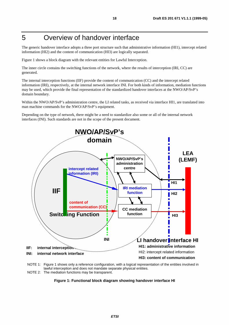
5 Overview of handover interfaceThe generic handover interface adopts a three port structure such that administrative information (HI1), intercept relatedinformation (HI2) and the content of communication (HI3) are logically separated.
Figure 1 shows a block diagram with the relevant entities for Lawful Interception.
The inner circle contains the switching functions of the network, where the results of interception (IRI, CC) aregenerated.
The internal interception functions (IIF) provide the content of communication (CC) and the intercept relatedinformation (IRI), respectively, at the internal network interface INI. For both kinds of information, mediation functionsmay be used, which provide the final representation of the standardized handover interfaces at the NWO/AP/SvP’sdomain boundary.
Within the NWO/AP/SvP’s administration centre, the LI related tasks, as received via interface HI1, are translated intoman machine commands for the NWO/AP/SvP’s equipment.
Depending on the type of network, there might be a need to standardize also some or all of the internal networkinterfaces (INI). Such standards are not in the scope of the present document.
NOTE 1: Figure 1 shows only a reference configuration, with a logical representation of the entities involved inlawful interception and does not mandate separate physical entities.
NOTE 2: The mediation functions may be transparent.
Figure 1: Functional block diagram showing handover interface HI
IIF: internal interception function
INI: internal network interface
content ofcommunication (CC)
NWO/AP/SvP’sdomain
intercept relatedinformation (IRI)
HI1
HI3
HI2
LI handover interface HIINI
NWO/AP/SvP’sadministration
centre
HI1: administrative informationHI2: intercept related information
HI3: content of communication
LEA(LEMF)
CC mediationfunctionSwitching Function
IIF IRI mediationfunction
ETSI
Draft ES 201 671 V1.1.1 (1999-05)19
5.1 Handover interface port 1 (HI1)The handover interface port 1 shall transport various kinds of administrative information from/to the LEA and theorganization at the NWO/AP/SvP, which is responsible for LI matters. This interface may be manual or electronic.
The HI1 interface may be crossing borders between countries. This possibility is subject to corresponding internationallaws or agreements.
A complete separation is required between the administrative part (HI1) and the technical part (INI) of the interface. Nodirect access to the switching function shall be given to the LEMF. Activation, deactivation or modification of aninterception in the switching function shall only be possible by the NWO/AP/SvP.
However, as an option, in direction to the LEA, some HI1 related information may be delivered directly.
Further description of HI1 is given in clause 7.
5.1.1 Manual interface
If the HI1 is designed as a manual interface, it will normally consist of paper documents. The request for lawfulinterception may be sent via letter or via fax to the administration centre of the NWO/AP/SvP. The personnel of theadministration centre will take the request and activate it in the network element (activation of interception). After theinterception specified in the warrant is activated, the LEA will be informed, see clause 7. From this point in time on, theLEA shall be prepared to receive intercept related information (IRI) via HI2 and content of communication (CC) viaHI3.
5.1.2 Electronic interface
An alternative solution may be the electronic transmission of the request for lawful interception. A practical system isfor further study. An initial definition of an HI1 mechanism may be found in the ASN.1 syntax of Annex A.
The information content shall be such that the authorized agent of the NWO/AP/SvP is able to map it to the informationwhich is required to activate the interception with a minimum of manual translation. This principle reduces theprobability of errors.
5.2 Handover interface port 2 (HI2)The handover interface port 2 shall transport the intercept related information (IRI) from the NWO/AP/SvP’s IIF to theLEMF.
The delivery shall be performed via data communication methods which are suitable for the network infrastructure andfor the kind and volume of data to be transmitted.
For the application layer, ROSE shall be used.
The delivery can in principle be made via different types of lower communication layers, which should be standard orwidely used data communication protocols.
The individual IRI parameters shall be coded using ASN.1 and the basic encoding rules (BER). The format of theparameter’s information content shall be based on existing telecommunication standards, where possible.
The IRI records contain information, which is available from the normal call handling procedures; additionally, theyinclude information for identification and control purposes, which is needed by the HI2 port. The IIF is not required tomake any attempt to request explicitly, via special call handling procedures, extra information, e.g. a calling partynumber, which has not already been supplied by a signalling system.
The HI2 data communication links and protocols provide a general means of data communication between the LEA andthe NWO/AP/SvP’s mediation function. It can in principle also be used for the transfer of other types of information,which logically belong to the interface ports HI1 and HI3. Specific ROSE components are used for these types ofinformation.
ETSI
Draft ES 201 671 V1.1.1 (1999-05)20
5.3 Handover interface port 3 (HI3)
5.3.1 Circuit switched, 64 kbit/s based services
The handover interface port 3 shall transport the content of communication from the NWO/AP/SvP’s mediation functionto the LEMF. For 64 kbit/s based services, the content of communication shall be delivered to the LEMF via circuit-switched 64 kbit/s connections. Two options exist; they depend on the infrastructure, which is used for delivery:
1) Standard circuit switched ISDN connections, set up on demand towards the LEMF, for each targetcommunication.
2) Use of a dedicated LI delivery network. The access to the delivery network shall use the same methods asdefined above, i.e. standard ISDN procedures. From the handover interface point of view, this option ishandled in the same way as method 1 above. No specific HI-relevant requirements are identified.
NOTE: The capacity of the HI3 connection to the LEMF should be adequate for the traffic which has to beintercepted.
5.3.2 User information messages
Delivery of user information messages, which are part of protocols for circuit switched connections, like UUS or SMS,may use dedicated ROSE components on the same lower layer data communication protocols as those used for the HI2port.
5.3.3 Packet switched data services
For further study.
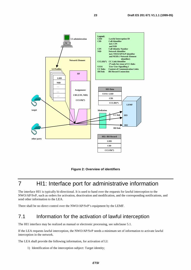
6 Specific identifiers for LI
6.1 Lawful interception identifier (LIID)For each target identity related to an interception measure, the authorized NWO/AP/SvP operator shall assign a speciallawful interception identifier (LIID), which has been agreed between the LEA and the NWO/AP/SvP. It is used withinparameters of all HI interface ports.
Using an indirect identification, pointing to a target identity makes it easier to keep the knowledge about a specificinterception target limited within the authorized NWO/AP/SvP operators and the handling agents at the LEA.
The lawful interception identifier LIID is a component of the CC (within set-up procedure of the CC link) and of the IRIrecords. It shall be used within any information exchanged at the handover interfaces HI2 and HI3 for identification andcorrelation purposes.
The LIID format shall consist of alphanumeric characters. It might for example, among other information, contain awarrant reference number, and the date, when the warrant was issued.
The authorized NWO/AP/SvP shall enter for each target identity of the interception subject a unique LIID.
EXAMPLE: The interception subject has an ISDN access with three MSNs. The NWO/AP/SvP enters for eachMSN an own LIID.
If more than one LEA intercepts the same target identity, there shall be unique LIIDs assigned, relating to each LEA.
6.2 Call identifier (CID)For each call or other activity relating to a target identity a CID is generated by the relevant network element. The CIDconsists of the following two identifiers:
ETSI
Draft ES 201 671 V1.1.1 (1999-05)21
• Network identifier (NID);
• Call Identity Number (CIN).
The CID distinguishes between the different calls of the target identity. It is also used for correlation between IRIrecords and CC connections. It is used at the interface ports HI2 and HI3.
The call identifier is specified in the subsections below. For ASN.1 coding details, see Annex A.
6.2.1 Network identifier (NID)
The network identifier is a mandatory parameter; it should be internationally unique. It consists of the following twoidentifiers:
1) NWO/AP/SvP- identifier (mandatory):Unique identification of network operator, access provider or service provider.
2) Network element identifier NEID (optional):The purpose of the network element identifier is to uniquely identify the relevant network element carryingout the LI operations, such as LI activation, IRI record sending, ... .
A network element identifier may be:
• an E.164 international node number in the case of circuit switched networks, such as ISDN, PSTN,GSM;
• a X.25 address;
• an IP address.
6.2.2 Call identity number (CIN)
The call identity number is a temporary identifier of an intercepted call, relating to a specific target identity, to identifyuniquely an intercepted call.
This parameter is mandatory for call related IRI.
6.3 CC link identifier (CCLID)This identifier is only used at the interface ports HI2 and HI3 in case of the reuse of CC links (option B, see subclause10.4.2).
For each CC link, which is set up by the mediation function towards the LEMF, a CC link identifier (CCLID) istransmitted in the HI2 records and HI3 setup message in addition to CIN and NID. For the correct correlation ofmultiparty calls this identity number indicates in the IRI records of each multiparty call, which CC link is used for thetransmission of the CC.
The CCLID may use the same format as the CIN; in this case, it need not be transmitted explicitly during set up of theCC links, as part of HI3. The CIN may also implicitly represent the CCLID.
6.4 Correlation between CC and IRITo assure correlation between the independently transmitted content of communication (CC) and intercept relatedinformation (IRI) of an intercepted call the following parameters are used:
• Lawful Interception Identifier (LIID), see subclause 6.1;
• Call Identifier (CID), see subclause 6.2;
• CC link identifier (CCLID), see subclause 6.3.
ETSI
Draft ES 201 671 V1.1.1 (1999-05)22
These parameters are transferred from the MF to the LEMF in:
• HI2: see subclause 8.4.1;
• HI3: see subclause 9.3.
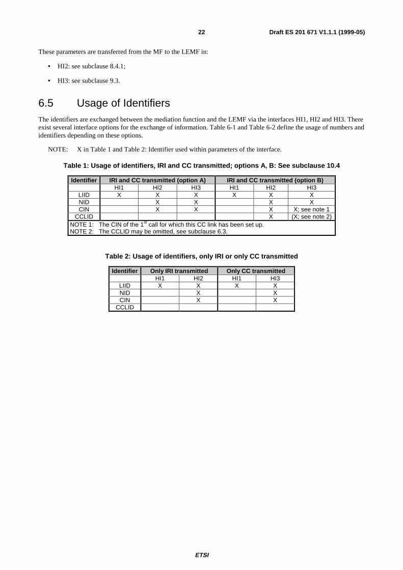
6.5 Usage of IdentifiersThe identifiers are exchanged between the mediation function and the LEMF via the interfaces HI1, HI2 and HI3. Thereexist several interface options for the exchange of information. Table 6-1 and Table 6-2 define the usage of numbers andidentifiers depending on these options.
NOTE: X in Table 1 and Table 2: Identifier used within parameters of the interface.
Table 1: Usage of identifiers, IRI and CC transmitted; options A, B: See subclause 10.4
Identifier IRI and CC transmitted (option A) IRI and CC transmitted (option B)HI1 HI2 HI3 HI1 HI2 HI3
LIID X X X X X XNID X X X XCIN X X X X; see note 1
CCLID X (X; see note 2)NOTE 1: The CIN of the 1st call for which this CC link has been set up.NOTE 2: The CCLID may be omitted, see subclause 6.3.
Table 2: Usage of identifiers, only IRI or only CC transmitted
Identifier Only IRI transmitted Only CC transmittedHI1 HI2 HI1 HI3
LIID X X X XNID X XCIN X X
CCLID
ETSI
Draft ES 201 671 V1.1.1 (1999-05)23
Figure 2: Overview of identifiers
7 HI1: Interface port for administrative informationThe interface HI1 is typically bi-directional. It is used to hand over the requests for lawful interception to theNWO/AP/SvP, such as orders for activation, deactivation and modification, and the corresponding notifications, andsend other information to the LEA.
There shall be no direct control over the NWO/AP/SvP’s equipment by the LEMF.
7.1 Information for the activation of lawful interceptionThe HI1 interface may be realized as manual or electronic processing, see subclause 5.1.
If the LEA requests lawful interception, the NWO/AP/SvP needs a minimum set of information to activate lawfulinterception in the network.
The LEA shall provide the following information, for activation of LI:
1) Identification of the interception subject: Target identity;
LI administration
LI Profiles
Network Element
target
LIID
IIF
other party
Assignment:
CID (CIN, NID)
CCLID(*)
CC link
LEMF
IRI link
Mediation
Legend:LIID Lawful Interception IDCID Call-Identifier incl. CIN and NIDCIN Call Identity NumberNID Network Identifier incl. NWO/AP/SvP identifier and NEID (=Network Element identifier)CCLID(*) CC Link Identifier (*) only for reuse of CC-linksUUS1 User User Signalling 1CC links Content of Communication LinksIRI link IRI Record Connection
HI3
HI2
HI2: IRI Record
LIID
CID
CCLID(*)
NID
....
....
....HI3 Data
UUS1: LIID
CID
CCLID(*)
ETSI
Draft ES 201 671 V1.1.1 (1999-05)24
2) The agreed lawful interception identifier (LIID);
3) Start and end (or duration) of the interception;
4) Further specification of type of interception:
• Kind of information to be provided (IRI, CC or both);
• Mode information (stereo / mono, see clause 9);
• Option A or B (reuse of CC links, see clause 10).
5) HI2 destination address of the LEMF, to which the IRI-Records shall be sent (if applicable);
6) HI3 destination address of the LEMF, to which the content of communication (CC) shall be sent (ifapplicable);
7) Other network dependent parameters (e.g. location information).
In addition, the following administrative information shall be included:
1) A reference for authorization of the interception.
2) Technical contact for issues relating to set-up and execution of the interception (e.g. solution of problemswith communication links to the LEMF).
7.2 LI notifications towards the LEMFLI management notifications to the LEMF shall be sent in the following cases:
1) After the activation of lawful interception.
2) After the deactivation of lawful interception.
3) After modification of an active lawful interception.
4) In case of certain exceptional situations.
For the definition of the information content of these LI management notifications, see clause A.4.
8 HI2: Interface port for intercept related informationThe HI2 interface port shall be used to transport all intercept related information (IRI), i.e. the information or dataassociated with the telecommunication services of the target identity apparent to the network. It includes signallinginformation used to establish the telecommunication service and to control its progress, time stamps, and, if available,further information such as supplementary service information or location information. Only information, which is partof standard signalling procedures shall be used within call related IRI, see also subclause 5.2; i.e. if a CLI of anoriginating other party is not available, it need not be requested from the origin, by extra procedures (this fact isdifferent from the principles normally applied, for example, for the malicious call identification service, MCID).
Sending of the intercept related information (IRI) to the LEMF shall in general take place as soon as possible, after therelevant information is available.
In exceptional cases (e.g. data link failure), the intercept related information may be buffered for later transmission for aspecified period of time.
8.1 Data transmission link, protocolThe protocol used by the "LI application" for the encoding and the sending of data between the MF and the LEMF isbased on ROSE components. ROSE (Remote Operation Service Element) is defined in the standards [35], [36] and [37].
ETSI
Draft ES 201 671 V1.1.1 (1999-05)25
This data communication method provides a general means of data communication between the LEA and theNWO/AP/SvP’s mediation function. It is used for the delivery of:
• HI1 type of information (notifications, alarms, ...);
• HI2 type of information (IRI records);
• HI3 data type of information (UUS, SMS, IP frames, X.25 packets, ...).
The ROSE protocol provides a clean separation of these kinds of information at application level.
The present document specifies only the use of ROSE on the application layer and the BER on the presentation layer.The lower layers for data communication may be chosen in agreement with the NWO/AP/SvP and the LEA.
The delivery to the LEMF should use standard or widely used lower layer data communication protocols. Someexamples for layers 1 to 3:
• Public X.25 network;
• ISDN B or D-channel (X.31 protocol);
• TCP/IP on Ethernet;
• TCP/IP on other network layer protocols (e.g. X.25).
Figure 3 illustrates the principle of the communication between the NWO/AP/SvP’s HI2 mediation function (MF) andthe LEA’s LEMF (HI2 interface port).
OSI Layer MF LEMFLI
7 Application ROSE ROSE6 Presentation BER BER5 Session4 Transport3 Network2 Link1 Physical
Protocol bridge at L3 Protocol repeater at L2
NOTE 1: A bridge between protocols has different network layer protocols on each side of the bridge.NOTE 2: A repeater has the same network protocol on each side.NOTE 3: The double headed arrows indicate peer relationships where each side has to be co-ordinated.NOTE 4: The LI operation is independent of the protocols of intervening networks (indicated by the bridge and
repeater).
Figure 3: Relation of LI application to OSI protocol stack
The MF and the LEMF are modeled as a pair of communicating entities that are separated by a number of interveningnetworks, which may use different communications hardware (e.g. 64 kbit/s circuit mode lines, TCP/IP packet networks,X.25 networks). ROSE, ASN.1 and BER provide a robust communications path between the two parts of the LIapplication.
8.1.1 Application for IRI (HI2 information)
As defined in subclause 5.2, the handover interface port 2 shall transport the intercept related information (IRI) from theNWO/AP/SvP’s MF to the LEMF.
The individual IRI parameters shall be coded using ASN.1 and the basic encoding rules (BER). Where possible, theformat of the information content shall be taken over from existing telecommunication standards, which are used forthese parameters with the network already, like the ISDN user part, DSS1 and MAP. Within the ASN.1 coding for IRI,such standard parameters are typically defined as octet strings.
ETSI
Draft ES 201 671 V1.1.1 (1999-05)26
8.1.2 Application for LI notifications (HI1) and CC (HI3)
See subclauses 7.2 and 9.2, respectively.
8.2 Definition of intercept related informationIntercept related information will in principle be available in the following phases of a call:
1) At call attempt initiation when the target identity becomes active, at which time call destination informationmay or may not be available (set up phase of a call, target may be the originating or terminating party, or beinvolved indirectly by a supplementary service).
2) At the end of a call attempt, when the target identity becomes inactive (release phase of call).
3) At certain times between the above phases, when relevant information becomes available (active phase ofcall).
In addition, information on non-call related actions of a target constitutes IRI and is sent via HI2, e.g. information onsubscriber controlled input.
The intercept related information (IRI) may be subdivided into the following categories:
1) Control information for HI2 (e.g. correlation information);
2) Basic call information, for standard calls between two parties;
3) Information related to supplementary services, which have been invoked during a call;
4) Information on non call related target actions.
8.3 Types of IRI recordsIntercept related information shall be conveyed to the LEMF in messages, or IRI data records, respectively. Four typesof IRI records are defined:
1) IRI-BEGIN record at the first event of a call or service attempt,opening the IRI transaction
2) IRI-END record at the end of a call or service attempt,closing the IRI transaction
3) IRI-CONTINUE record at any time during a call or service attemptwithin the IRI transaction
4) IRI-REPORT record used in general for non call related events
For information related to an existing call, the record types 1 to 3 shall be used. They form an IRI transaction for eachcall or call attempt, which corresponds directly to the sequence of the call (set-up, active phase, release).
Record type 4 is used for non call related subscriber action, like subscriber controlled input (SCI) for service activation.For simple calls, it can be applicable for unsuccessful call attempts.
The record type is an explicit part of the record. The 4 record types are defined independently of target call events. Theactual indication of one or several call events, which caused the generation of an IRI record, is part of further parameterswithin the record’s, information content. Consequently, the record types of the IRI transactions are not related to specificmessages of the signalling protocols of a call, and are therefore independent of future enhancements of the interceptedservices, of network specific features, etc. Any information on the target call state or other target call related informationis contained within the information content of the IRI records.
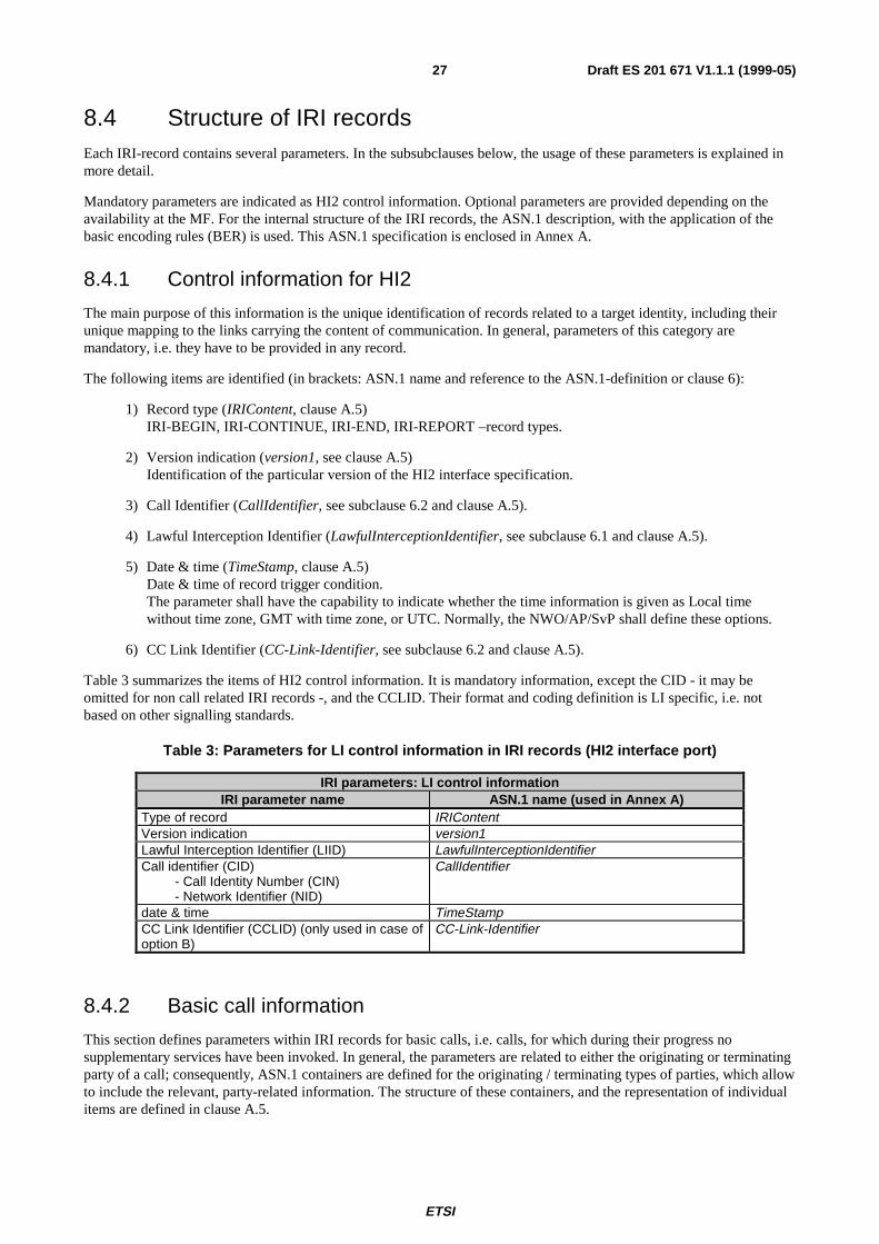
ETSI
Draft ES 201 671 V1.1.1 (1999-05)27
8.4 Structure of IRI recordsEach IRI-record contains several parameters. In the subsubclauses below, the usage of these parameters is explained inmore detail.
Mandatory parameters are indicated as HI2 control information. Optional parameters are provided depending on theavailability at the MF. For the internal structure of the IRI records, the ASN.1 description, with the application of thebasic encoding rules (BER) is used. This ASN.1 specification is enclosed in Annex A.
8.4.1 Control information for HI2
The main purpose of this information is the unique identification of records related to a target identity, including theirunique mapping to the links carrying the content of communication. In general, parameters of this category aremandatory, i.e. they have to be provided in any record.
The following items are identified (in brackets: ASN.1 name and reference to the ASN.1-definition or clause 6):
1) Record type (IRIContent, clause A.5)IRI-BEGIN, IRI-CONTINUE, IRI-END, IRI-REPORT –record types.
2) Version indication (version1, see clause A.5)Identification of the particular version of the HI2 interface specification.
3) Call Identifier (CallIdentifier, see subclause 6.2 and clause A.5).
4) Lawful Interception Identifier (LawfulInterceptionIdentifier, see subclause 6.1 and clause A.5).
5) Date & time (TimeStamp, clause A.5)Date & time of record trigger condition.The parameter shall have the capability to indicate whether the time information is given as Local timewithout time zone, GMT with time zone, or UTC. Normally, the NWO/AP/SvP shall define these options.
6) CC Link Identifier (CC-Link-Identifier, see subclause 6.2 and clause A.5).
Table 3 summarizes the items of HI2 control information. It is mandatory information, except the CID - it may beomitted for non call related IRI records -, and the CCLID. Their format and coding definition is LI specific, i.e. notbased on other signalling standards.
Table 3: Parameters for LI control information in IRI records (HI2 interface port)
IRI parameters: LI control informationIRI parameter name ASN.1 name (used in Annex A)
Type of record IRIContentVersion indication version1Lawful Interception Identifier (LIID) LawfulInterceptionIdentifierCall identifier (CID) - Call Identity Number (CIN) - Network Identifier (NID)
CallIdentifier
date & time TimeStampCC Link Identifier (CCLID) (only used in case ofoption B)
CC-Link-Identifier
8.4.2 Basic call information
This section defines parameters within IRI records for basic calls, i.e. calls, for which during their progress nosupplementary services have been invoked. In general, the parameters are related to either the originating or terminatingparty of a call; consequently, ASN.1 containers are defined for the originating / terminating types of parties, which allowto include the relevant, party-related information. The structure of these containers, and the representation of individualitems are defined in clause A.5.
ETSI
Draft ES 201 671 V1.1.1 (1999-05)28
NOTE: A third type of party information is defined for the forwarded-to-party (see subclause 8.4.3 on calls withsupplementary services being invoked).
The items below are to be included, when they become available for the first time during a call in progress. If the sameitem appears identically several times during a call, it needs only to be transmitted once, e.g. in an IRI-BEGIN record.The ASN.1 name of the respective parameters, as defined in clause A.5, is indicated in brackets.
1) Direction of call (intercept_Call_Direct)Indication, whether the target identity is orig. or term. Party.
2) Address of originating and terminating parties (CallingPartyNumber or CalledPartyNumber)If e.g. in case of call originated by the target at transmission of the IRI-BEGIN record only a partialterminating address is available, it shall be transmitted, the complete address shall follow, when available.
3) Basic Service, LLC (Services-Information)Parameters as received from signalling protocol (e.g. BC, HLC, TMR, LLC).
4) Cause (ISUP_parameters or DSS1_parameters_codeset_0)Reason for release of intercepted call. Cause value as received from signalling protocol. It is transmitted withthe ASN.1 container of the party, which initiated the release; in case of a network initiated release, it may beeither one.
5) Additional network parametersE.g. location information (Location).
Parameters defined within Table 4 and Table 5 shall be used for existing services, in the given ETSI format. Nationalextensions may be possible using the ASN.1 parameter National-Parameters.
8.4.3 Information on supplementary services, related to a call in progress
The general principle is, to transmit service related information within IRI records, when the correspondingevent/information, which needs to be conveyed to the LEMF, is received from the signalling protocol. Where possible,the coding of the related information shall use the same formats as defined by standard signalling protocols.
The selection, which types of events or information elements are relevant for transmission to the LEAs is conforming tothe requirements defined in [1] and [2].
A dedicated ASN.1 parameter is defined for supplementary services related to forwarding or re-routing calls(forwarded-to-Party information), due to the major relevance of these kind of services with respect to LI. For thevarious cases of forwarded calls, the information related to forwarding is included in the originatingParty /terminatingParty / forwarded-to-Party information:
1) If a call to the target has been previously forwarded, available parameters relating to the redirecting party(ies)are encapsulated within the originatingPartyInformation parameter.
2) If the call is forwarded at the target’s access (conditional or unconditional forwarding towards the forwarded-to-party), parameters related to the redirecting party (target) are encapsulated within theterminatingPartyInformation parameter.
3) All parameters related to the forwarded-to-party or beyond the forwarded-to-party are encapsulated within theforwarded-to-Party ASN1 coded parameter. In addition, this parameter includes thesupplementary_Services_Information, containing the forwarded-to address, and the redirection informationparameter, with the reason of the call forwarding, the number of redirection, ...).
For the detailed specification of supplementary services related procedures see clause 10.
Parameters defined within Table 4 and Table 5 shall be used for existing services, in the given ETSI format. Nationalextensions may be possible using the ASN.1 parameter National-Parameters.
8.4.4 Information on non call related supplementary services
The general principle is, to transmit non call related service information as received from the signalling protocol.
ETSI
Draft ES 201 671 V1.1.1 (1999-05)29
A typical user action to be reported is subscriber controlled input (SCI).
For the detailed specification of the related procedures see clause 10.
8.5 Selection of parameters for IRI recordsRelevant information on a call is taken from the call handling process, using wherever possible the coding specificationsof the standardized ISDN protocols, or other standard network protocols. The protocol-defined information content iscopied transparently into the information elements of the IRI records. This principle enables to reuse of internationallyagreed standardization results; it allows reuse of existing functions within the NWO/AP/SvP equipment and in theterminal area (LEMF).
Consequently, the present document needs for a large number of IRI-relevant items only to refer to other, existingstandards, instead of including separate definitions in its scope. By this principle, also consistency issues anddependencies on the ongoing enhancements of the various protocols are minimized.
The relevant parameters are listed in Table 4 and Table 5.
For other signalling systems, which are not included in Table 4, the parameters shall be interpreted on a functional level,for defining their applicability in an IRI record; e.g. in case of a local call between analogue users, the called partynumber may only exist in an internal format of the switching system. Within the IRI records, such parameters shall alsouse the standardized coding. Existing interworking specifications, like [14] shall be used for the conversion to thestandard format. If the signalling system provides less information than defined by the standards in Table 4, spare ordefault values may be used instead.
This method avoids the need to analyze for all situations, especially in the area of supplementary services, each detail ofthe service procedures, with specification of which parameter shall be sent in which state or situation. Instead, only areference to the applicable standards is made. As soon as a parameter defined in one of the parameter tables appearswithin the target call protocol, it shall be transmitted within an IRI record.
In addition to parameters taken from the call handling process, further, lawful interception specific parameters areneeded, like the control information for LI.
Three types of origins for the specification of HI2 parameters in IRI records can be differentiated:
1) Parameters for LI control information; they are specific for the LI HI2 interface, and are specified in thepresent document (Table 3).
2) Parameters used to convey information to the LEMF, which is retrieved from the target’s call or servicesignalling protocol information (Table 4). Within the IRI a standardized protocol coding is used.
The relevant protocol specifications are the ISDN user part, as a generic protocol, used by several types ofnetworks, and dedicated network protocols, e.g. DSS1 or GSM standards. For a common implementation indifferent countries and to guarantee the possibility of an interception measure across borders only parametersdefined in ETSI standards shall be used.
3) Parameters used to convey information from events relating to the target call, but with no equivalentparameters being available in protocol standards. Such parameters shall be specified in the present document(Table 5).
The LI control information is a mandatory part of each IRI record (exception: CID), the information defined in Table 4and Table 5 is included in IRI records, if the according parameter or event is detected during processing a call or a targetidentity related action.
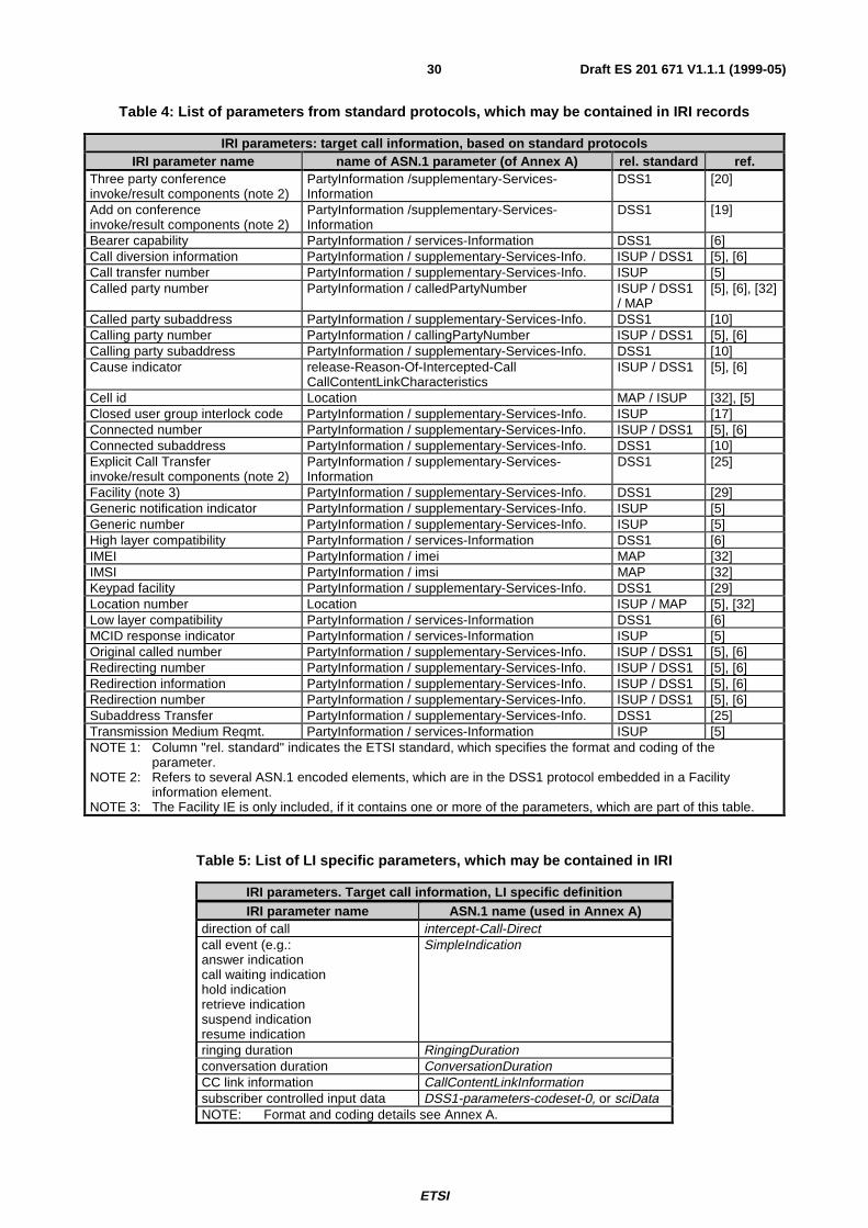
ETSI
Draft ES 201 671 V1.1.1 (1999-05)30
Table 4: List of parameters from standard protocols, which may be contained in IRI records
IRI parameters: target call information, based on standard protocolsIRI parameter name name of ASN.1 parameter (of Annex A) rel. standard ref.
Three party conferenceinvoke/result components (note 2)
PartyInformation /supplementary-Services-Information
DSS1 [20]
Add on conferenceinvoke/result components (note 2)
PartyInformation /supplementary-Services-Information
DSS1 [19]
Bearer capability PartyInformation / services-Information DSS1 [6]Call diversion information PartyInformation / supplementary-Services-Info. ISUP / DSS1 [5], [6]Call transfer number PartyInformation / supplementary-Services-Info. ISUP [5]Called party number PartyInformation / calledPartyNumber ISUP / DSS1
/ MAP[5], [6], [32]
Called party subaddress PartyInformation / supplementary-Services-Info. DSS1 [10]Calling party number PartyInformation / callingPartyNumber ISUP / DSS1 [5], [6]Calling party subaddress PartyInformation / supplementary-Services-Info. DSS1 [10]Cause indicator release-Reason-Of-Intercepted-Call
CallContentLinkCharacteristicsISUP / DSS1 [5], [6]
Cell id Location MAP / ISUP [32], [5]Closed user group interlock code PartyInformation / supplementary-Services-Info. ISUP [17]Connected number PartyInformation / supplementary-Services-Info. ISUP / DSS1 [5], [6]Connected subaddress PartyInformation / supplementary-Services-Info. DSS1 [10]Explicit Call Transferinvoke/result components (note 2)
PartyInformation / supplementary-Services-Information
DSS1 [25]
Facility (note 3) PartyInformation / supplementary-Services-Info. DSS1 [29]Generic notification indicator PartyInformation / supplementary-Services-Info. ISUP [5]Generic number PartyInformation / supplementary-Services-Info. ISUP [5]High layer compatibility PartyInformation / services-Information DSS1 [6]IMEI PartyInformation / imei MAP [32]IMSI PartyInformation / imsi MAP [32]Keypad facility PartyInformation / supplementary-Services-Info. DSS1 [29]Location number Location ISUP / MAP [5], [32]Low layer compatibility PartyInformation / services-Information DSS1 [6]MCID response indicator PartyInformation / services-Information ISUP [5]Original called number PartyInformation / supplementary-Services-Info. ISUP / DSS1 [5], [6]Redirecting number PartyInformation / supplementary-Services-Info. ISUP / DSS1 [5], [6]Redirection information PartyInformation / supplementary-Services-Info. ISUP / DSS1 [5], [6]Redirection number PartyInformation / supplementary-Services-Info. ISUP / DSS1 [5], [6]Subaddress Transfer PartyInformation / supplementary-Services-Info. DSS1 [25]Transmission Medium Reqmt. PartyInformation / services-Information ISUP [5]NOTE 1: Column "rel. standard" indicates the ETSI standard, which specifies the format and coding of the
parameter.NOTE 2: Refers to several ASN.1 encoded elements, which are in the DSS1 protocol embedded in a Facility
information element.NOTE 3: The Facility IE is only included, if it contains one or more of the parameters, which are part of this table.
Table 5: List of LI specific parameters, which may be contained in IRI
IRI parameters. Target call information, LI specific definitionIRI parameter name ASN.1 name (used in Annex A)
direction of call intercept-Call-Directcall event (e.g.:answer indicationcall waiting indicationhold indicationretrieve indicationsuspend indicationresume indication
SimpleIndication
ringing duration RingingDurationconversation duration ConversationDurationCC link information CallContentLinkInformationsubscriber controlled input data DSS1-parameters-codeset-0, or sciDataNOTE: Format and coding details see Annex A.
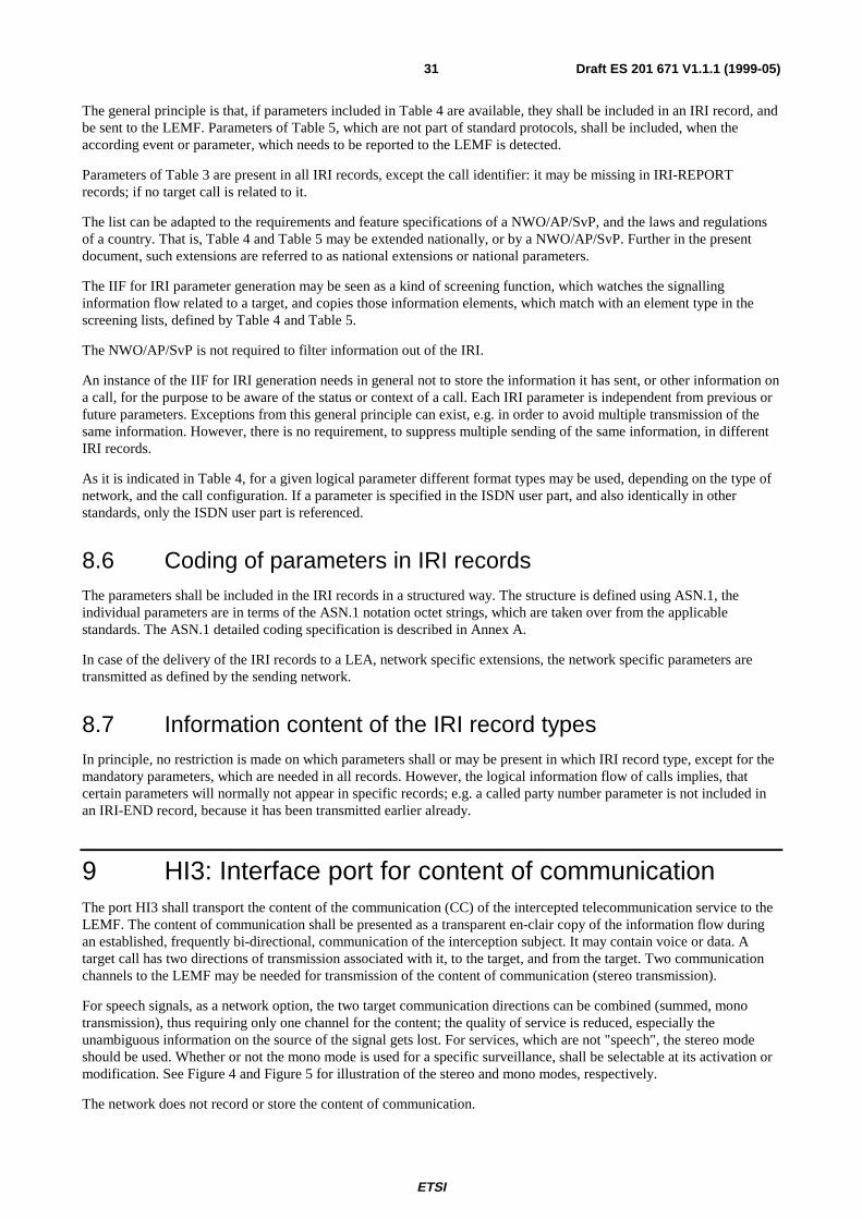
ETSI
Draft ES 201 671 V1.1.1 (1999-05)31
The general principle is that, if parameters included in Table 4 are available, they shall be included in an IRI record, andbe sent to the LEMF. Parameters of Table 5, which are not part of standard protocols, shall be included, when theaccording event or parameter, which needs to be reported to the LEMF is detected.
Parameters of Table 3 are present in all IRI records, except the call identifier: it may be missing in IRI-REPORTrecords; if no target call is related to it.
The list can be adapted to the requirements and feature specifications of a NWO/AP/SvP, and the laws and regulationsof a country. That is, Table 4 and Table 5 may be extended nationally, or by a NWO/AP/SvP. Further in the presentdocument, such extensions are referred to as national extensions or national parameters.
The IIF for IRI parameter generation may be seen as a kind of screening function, which watches the signallinginformation flow related to a target, and copies those information elements, which match with an element type in thescreening lists, defined by Table 4 and Table 5.
The NWO/AP/SvP is not required to filter information out of the IRI.
An instance of the IIF for IRI generation needs in general not to store the information it has sent, or other information ona call, for the purpose to be aware of the status or context of a call. Each IRI parameter is independent from previous orfuture parameters. Exceptions from this general principle can exist, e.g. in order to avoid multiple transmission of thesame information. However, there is no requirement, to suppress multiple sending of the same information, in differentIRI records.
As it is indicated in Table 4, for a given logical parameter different format types may be used, depending on the type ofnetwork, and the call configuration. If a parameter is specified in the ISDN user part, and also identically in otherstandards, only the ISDN user part is referenced.
8.6 Coding of parameters in IRI recordsThe parameters shall be included in the IRI records in a structured way. The structure is defined using ASN.1, theindividual parameters are in terms of the ASN.1 notation octet strings, which are taken over from the applicablestandards. The ASN.1 detailed coding specification is described in Annex A.
In case of the delivery of the IRI records to a LEA, network specific extensions, the network specific parameters aretransmitted as defined by the sending network.
8.7 Information content of the IRI record typesIn principle, no restriction is made on which parameters shall or may be present in which IRI record type, except for themandatory parameters, which are needed in all records. However, the logical information flow of calls implies, thatcertain parameters will normally not appear in specific records; e.g. a called party number parameter is not included inan IRI-END record, because it has been transmitted earlier already.
9 HI3: Interface port for content of communicationThe port HI3 shall transport the content of the communication (CC) of the intercepted telecommunication service to theLEMF. The content of communication shall be presented as a transparent en-clair copy of the information flow duringan established, frequently bi-directional, communication of the interception subject. It may contain voice or data. Atarget call has two directions of transmission associated with it, to the target, and from the target. Two communicationchannels to the LEMF may be needed for transmission of the content of communication (stereo transmission).
For speech signals, as a network option, the two target communication directions can be combined (summed, monotransmission), thus requiring only one channel for the content; the quality of service is reduced, especially theunambiguous information on the source of the signal gets lost. For services, which are not "speech", the stereo modeshould be used. Whether or not the mono mode is used for a specific surveillance, shall be selectable at its activation ormodification. See Figure 4 and Figure 5 for illustration of the stereo and mono modes, respectively.
The network does not record or store the content of communication.
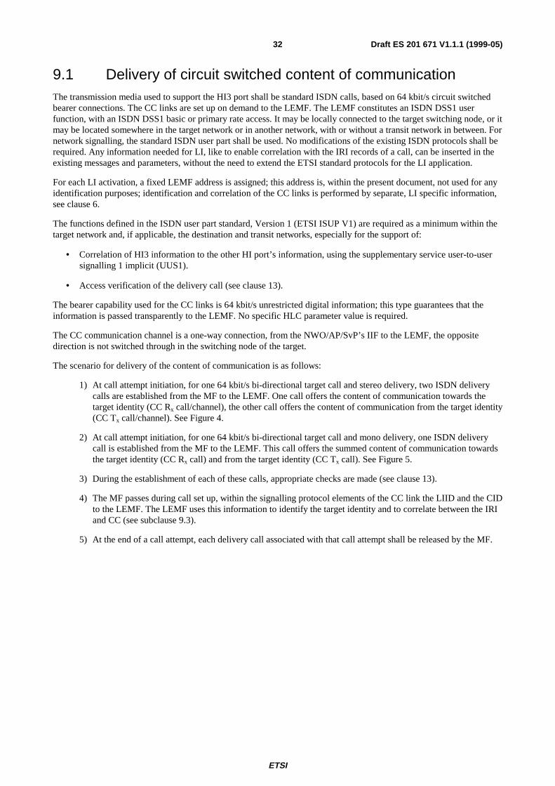
ETSI
Draft ES 201 671 V1.1.1 (1999-05)32
9.1 Delivery of circuit switched content of communicationThe transmission media used to support the HI3 port shall be standard ISDN calls, based on 64 kbit/s circuit switchedbearer connections. The CC links are set up on demand to the LEMF. The LEMF constitutes an ISDN DSS1 userfunction, with an ISDN DSS1 basic or primary rate access. It may be locally connected to the target switching node, or itmay be located somewhere in the target network or in another network, with or without a transit network in between. Fornetwork signalling, the standard ISDN user part shall be used. No modifications of the existing ISDN protocols shall berequired. Any information needed for LI, like to enable correlation with the IRI records of a call, can be inserted in theexisting messages and parameters, without the need to extend the ETSI standard protocols for the LI application.
For each LI activation, a fixed LEMF address is assigned; this address is, within the present document, not used for anyidentification purposes; identification and correlation of the CC links is performed by separate, LI specific information,see clause 6.
The functions defined in the ISDN user part standard, Version 1 (ETSI ISUP V1) are required as a minimum within thetarget network and, if applicable, the destination and transit networks, especially for the support of:
• Correlation of HI3 information to the other HI port’s information, using the supplementary service user-to-usersignalling 1 implicit (UUS1).
• Access verification of the delivery call (see clause 13).
The bearer capability used for the CC links is 64 kbit/s unrestricted digital information; this type guarantees that theinformation is passed transparently to the LEMF. No specific HLC parameter value is required.
The CC communication channel is a one-way connection, from the NWO/AP/SvP’s IIF to the LEMF, the oppositedirection is not switched through in the switching node of the target.
The scenario for delivery of the content of communication is as follows:
1) At call attempt initiation, for one 64 kbit/s bi-directional target call and stereo delivery, two ISDN deliverycalls are established from the MF to the LEMF. One call offers the content of communication towards thetarget identity (CC Rx call/channel), the other call offers the content of communication from the target identity(CC Tx call/channel). See Figure 4.
2) At call attempt initiation, for one 64 kbit/s bi-directional target call and mono delivery, one ISDN deliverycall is established from the MF to the LEMF. This call offers the summed content of communication towardsthe target identity (CC Rx call) and from the target identity (CC Tx call). See Figure 5.
3) During the establishment of each of these calls, appropriate checks are made (see clause 13).
4) The MF passes during call set up, within the signalling protocol elements of the CC link the LIID and the CIDto the LEMF. The LEMF uses this information to identify the target identity and to correlate between the IRIand CC (see subclause 9.3).
5) At the end of a call attempt, each delivery call associated with that call attempt shall be released by the MF.
ETSI
Draft ES 201 671 V1.1.1 (1999-05)33
Figure 4: Content of communication transmission from MF to LEMF, stereo mode
Figure 5: Content of communication transmission from MF to LEMF, mono mode
9.2 Delivery of packetized content of communication (general)For packetized content of communication, the same physical link as used for HI2, or a dedicated link may be used. TheROSE operations for the transmission of the content of communication (HI3 data interface) shall follow the same rulesas the one defined for the HI2 interface in subclause 8.1.
A differentiation is made between:
TargetT
LEMF
other partyP
IIF
MF
Txbearer channel,
signalling channel
Rxbearer channel,signalling channel
TargetT
IIF
LEMF
MF
other partyP
Sum of Tx + Rxbearer channel,
signalling channel
+
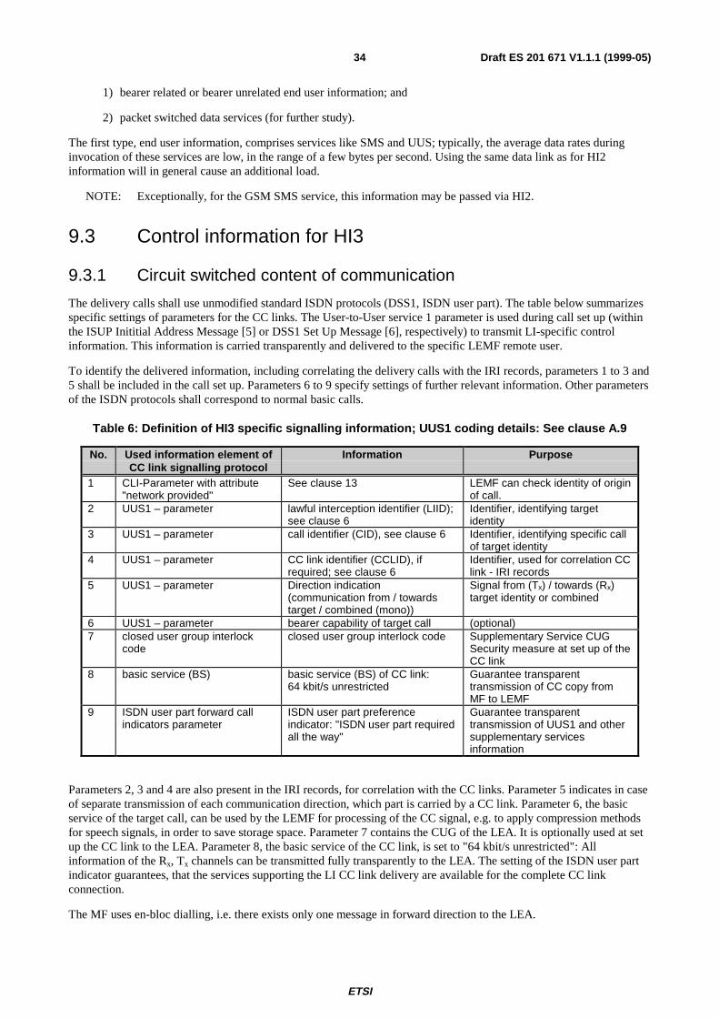
ETSI
Draft ES 201 671 V1.1.1 (1999-05)34
1) bearer related or bearer unrelated end user information; and
2) packet switched data services (for further study).
The first type, end user information, comprises services like SMS and UUS; typically, the average data rates duringinvocation of these services are low, in the range of a few bytes per second. Using the same data link as for HI2information will in general cause an additional load.
NOTE: Exceptionally, for the GSM SMS service, this information may be passed via HI2.
9.3 Control information for HI3
9.3.1 Circuit switched content of communication
The delivery calls shall use unmodified standard ISDN protocols (DSS1, ISDN user part). The table below summarizesspecific settings of parameters for the CC links. The User-to-User service 1 parameter is used during call set up (withinthe ISUP Inititial Address Message [5] or DSS1 Set Up Message [6], respectively) to transmit LI-specific controlinformation. This information is carried transparently and delivered to the specific LEMF remote user.
To identify the delivered information, including correlating the delivery calls with the IRI records, parameters 1 to 3 and5 shall be included in the call set up. Parameters 6 to 9 specify settings of further relevant information. Other parametersof the ISDN protocols shall correspond to normal basic calls.
Table 6: Definition of HI3 specific signalling information; UUS1 coding details: See clause A.9
No. Used information element ofCC link signalling protocol
Information Purpose
1 CLI-Parameter with attribute"network provided"
See clause 13 LEMF can check identity of originof call.
2 UUS1 – parameter lawful interception identifier (LIID);see clause 6
Identifier, identifying targetidentity
3 UUS1 – parameter call identifier (CID), see clause 6 Identifier, identifying specific callof target identity
4 UUS1 – parameter CC link identifier (CCLID), ifrequired; see clause 6
Identifier, used for correlation CClink - IRI records
5 UUS1 – parameter Direction indication(communication from / towardstarget / combined (mono))
Signal from (Tx) / towards (Rx)target identity or combined
6 UUS1 – parameter bearer capability of target call (optional)7 closed user group interlock
codeclosed user group interlock code Supplementary Service CUG
Security measure at set up of theCC link
8 basic service (BS) basic service (BS) of CC link:64 kbit/s unrestricted
Guarantee transparenttransmission of CC copy fromMF to LEMF
9 ISDN user part forward callindicators parameter
ISDN user part preferenceindicator: "ISDN user part requiredall the way"
Guarantee transparenttransmission of UUS1 and othersupplementary servicesinformation
Parameters 2, 3 and 4 are also present in the IRI records, for correlation with the CC links. Parameter 5 indicates in caseof separate transmission of each communication direction, which part is carried by a CC link. Parameter 6, the basicservice of the target call, can be used by the LEMF for processing of the CC signal, e.g. to apply compression methodsfor speech signals, in order to save storage space. Parameter 7 contains the CUG of the LEA. It is optionally used at setup the CC link to the LEA. Parameter 8, the basic service of the CC link, is set to "64 kbit/s unrestricted": Allinformation of the Rx, Tx channels can be transmitted fully transparently to the LEA. The setting of the ISDN user partindicator guarantees, that the services supporting the LI CC link delivery are available for the complete CC linkconnection.
The MF uses en-bloc dialling, i.e. there exists only one message in forward direction to the LEA.
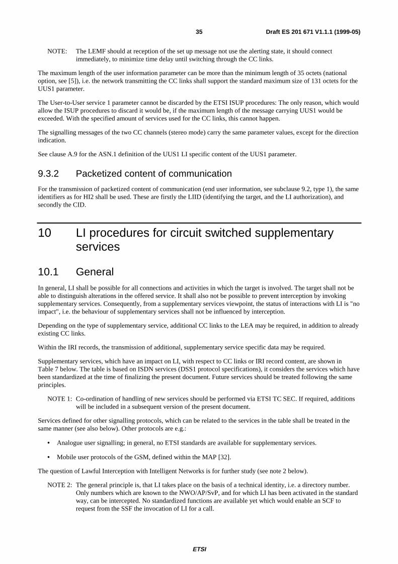
ETSI
Draft ES 201 671 V1.1.1 (1999-05)35
NOTE: The LEMF should at reception of the set up message not use the alerting state, it should connectimmediately, to minimize time delay until switching through the CC links.
The maximum length of the user information parameter can be more than the minimum length of 35 octets (nationaloption, see [5]), i.e. the network transmitting the CC links shall support the standard maximum size of 131 octets for theUUS1 parameter.
The User-to-User service 1 parameter cannot be discarded by the ETSI ISUP procedures: The only reason, which wouldallow the ISUP procedures to discard it would be, if the maximum length of the message carrying UUS1 would beexceeded. With the specified amount of services used for the CC links, this cannot happen.
The signalling messages of the two CC channels (stereo mode) carry the same parameter values, except for the directionindication.
See clause A.9 for the ASN.1 definition of the UUS1 LI specific content of the UUS1 parameter.
9.3.2 Packetized content of communication
For the transmission of packetized content of communication (end user information, see subclause 9.2, type 1), the sameidentifiers as for HI2 shall be used. These are firstly the LIID (identifying the target, and the LI authorization), andsecondly the CID.
10 LI procedures for circuit switched supplementaryservices
10.1 GeneralIn general, LI shall be possible for all connections and activities in which the target is involved. The target shall not beable to distinguish alterations in the offered service. It shall also not be possible to prevent interception by invokingsupplementary services. Consequently, from a supplementary services viewpoint, the status of interactions with LI is "noimpact", i.e. the behaviour of supplementary services shall not be influenced by interception.
Depending on the type of supplementary service, additional CC links to the LEA may be required, in addition to alreadyexisting CC links.
Within the IRI records, the transmission of additional, supplementary service specific data may be required.
Supplementary services, which have an impact on LI, with respect to CC links or IRI record content, are shown inTable 7 below. The table is based on ISDN services (DSS1 protocol specifications), it considers the services which havebeen standardized at the time of finalizing the present document. Future services should be treated following the sameprinciples.
NOTE 1: Co-ordination of handling of new services should be performed via ETSI TC SEC. If required, additionswill be included in a subsequent version of the present document.
Services defined for other signalling protocols, which can be related to the services in the table shall be treated in thesame manner (see also below). Other protocols are e.g.:
• Analogue user signalling; in general, no ETSI standards are available for supplementary services.
• Mobile user protocols of the GSM, defined within the MAP [32].
The question of Lawful Interception with Intelligent Networks is for further study (see note 2 below).
NOTE 2: The general principle is, that LI takes place on the basis of a technical identity, i.e. a directory number.Only numbers which are known to the NWO/AP/SvP, and for which LI has been activated in the standardway, can be intercepted. No standardized functions are available yet which would enable an SCF torequest from the SSF the invocation of LI for a call.
ETSI
Draft ES 201 671 V1.1.1 (1999-05)36
Additional CC links are only required, if the target is the served user. IRI Records may also carry data from other partiesbeing served users.
Annex B specifies details for relevant services:
• The procedures for CC links, depending on the call scenario of the target.
• Related to the IRI records, the point in time of sending and supplementary service specific information.
• Additional remarks for services with "no impact" on LI.
The specifications for supplementary services interactions are kept as far as possible independent of the details of theused signalling protocols; service related events are therefore described in more general terms, rather than using protocoldependent messages or parameters.
Interactions with services of the same family, like call diversion services, are commonly specified, if the individualservices behavior is identical, with respect to LI.
With respect to the IRI records, Annex B specifies typical cases; the general rules for data which shall be included in IRIrecords are defined in clause 8, specifically in subclause 8.5, and subclause 10.3 below.
Services which are not part of the Table 7 do not require the generation of LI information: No CC links are generated ormodified, and no specific information on the service is present in the IRI records. That is, these services have "noimpact" on LI, no special functions for LI are required. However, within the IIF, functions may be required to realize theprinciple, that the service behaviour shall not be influenced by LI.
"No impact" is not automatically applicable for new services. Each new service has to be checked for its impact on LI.Additionally, also services using other than the DSS1 protocols, which cannot be related to one of the DSS1 basedservices, may have impact on LI.
The present document does not intend to give a complete description of all possible cases and access types ofinteractions with supplementary services.
10.2 CC link ImpactThe column "CC links: additional calls, impact" (Table 7) defines, whether:
• for the related service CC links shall be set up, in addition to the CC links for a basic call;
• already existing calls are impacted, for example by disconnecting their information flow.
The CC link impact relates always to actions of a target being the served user. Services invoked by other parties have noCC link impact.
10.3 IRI Impact, General Principle for Sending IRI recordsThe column "IRI items related to service" (Table 7) specifies, which parameters may be transmitted to the LEA withinthe IRI records. For several services, it is differentiated, whether the target or the other party is the served user(underlined in table).
The table specifies, which parameters are applicable in principle. That is, these parameters are normally sent to the LEA,immediately when they are available from the protocol procedures of the service. In many cases, additional IRI-CONTINUE records, compared to a basic call, will be generated. However, not each service related signalling eventneeds to be sent immediately within an individual record. Exceptions may exist, where several events are included inone record, even if this would result in some delay of reporting an event (this may be implementation dependent). Eachrecord shall contain all information, which is required by the LEA to enable the interpretation of an action; example: theindication of call forwarding by the target shall include the forwarded-to number and the indication of the type offorwarding within the same record.
The complete set of parameters, which are applicable for IRI, is specified in subclause 8.5 (Table 4 and Table 5).
ETSI
Draft ES 201 671 V1.1.1 (1999-05)37
If during procedures involving supplementary services protocol parameters, which are listed in Table 4 and Table 5become available, they shall be included in IRI Records. This rule is directly applicable for parameters received viaISUP and DSS1 signalling protocols. Regarding all other protocols, e.g. of analogue users, the mapping to the ISDNprotocols, as defined in subclause 8.5 is assumed, before discriminating, which (mapped) parameters are copied to theIRI records. For parameters of ETSI-standardized services, like GSM services, which cannot be mapped to ISUPparameters, the specific coding, e.g. of the MAP [32] may be used, instead of mapping the information to DSS1parameters.
IRI data are not stored by the IIF or MF for the purpose of keeping information on call context or call configuration,including complex multiparty calls. The LEMF (electronically) or the LEA’s agent (manually) shall always be able, tofind out the relevant history on the call configuration, to the extent, which is given by the available signalling protocolbased information, within the telecommunication network.
Service invocations, which result in invoke and return result components (as defined in Table 4) need only be reportedin case of successful invocations. One IRI record, containing the invoke component, possibly including additionalparameters from the return result component, is sufficient. Instead of the DSS1 functional protocol components, forspecific networks other ETSI-standardized components may be used, e.g. of the MAP [32].
With respect to the inclusion of LI specific parameters, see also the parameter specifications and example scenarios inAnnex E for more details.
Details of e.g. the definition of the used record type, their content, the exact points in time of sending etc. follow fromthe according service specifications; in some cases, they are specified explicitly in the normative Annex B and in theinformative Annex E.
10.4 Multi party calls – general principles, options A, BWith respect to IRI, each call or call leg owns a separate IRI transaction sequence, independent of whether it is actuallyactive or not.
With respect to the CC links, two options (A, B) exist, which depend on laws, regulations and LEA requirements, seebelow. Active call or call leg means in this context, that the target is actually in communication with the other party ofthat call or call leg; this definition differs from the definition in [6].
10.4.1 CC links for active and non-active calls (option A)
For each call, active or not, separate CC links shall be provided. This guarantees, that:
• changes in the call configuration of the target are reflected immediately, with no delay, at the LEMF;
• the signal from held parties can still be intercepted.
It is a network option, whether the communication direction of a non-active call, which still carries a signal from theother party, is switched through to the LEMF, or switched off.
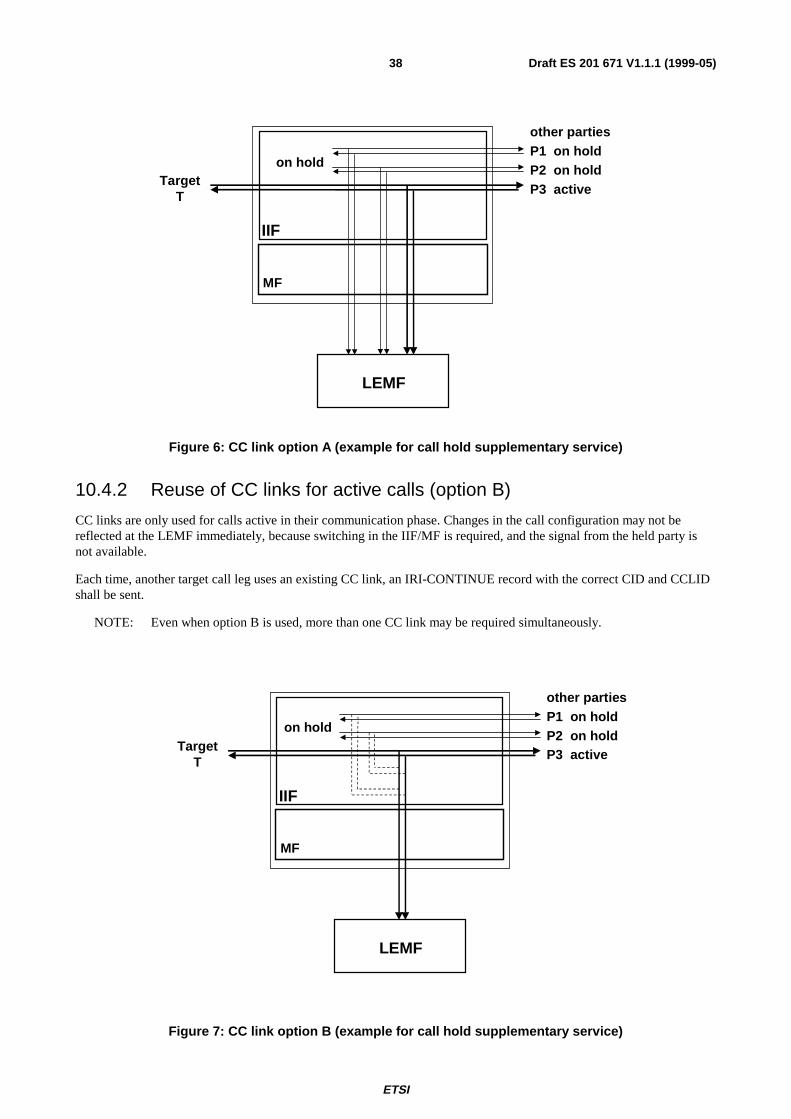
ETSI
Draft ES 201 671 V1.1.1 (1999-05)38
Figure 6: CC link option A (example for call hold supplementary service)
10.4.2 Reuse of CC links for active calls (option B)
CC links are only used for calls active in their communication phase. Changes in the call configuration may not bereflected at the LEMF immediately, because switching in the IIF/MF is required, and the signal from the held party isnot available.
Each time, another target call leg uses an existing CC link, an IRI-CONTINUE record with the correct CID and CCLIDshall be sent.
NOTE: Even when option B is used, more than one CC link may be required simultaneously.
Figure 7: CC link option B (example for call hold supplementary service)
TargetT
other partiesP1 on holdP2 on holdP3 active
IIF
LEMF
MF
on hold
TargetT
other partiesP1 on holdP2 on holdP3 active
IIF
LEMF
MF
on hold
ETSI
Draft ES 201 671 V1.1.1 (1999-05)39
10.5 Subscriber Controlled Input (SCI): Activation / Deactivation /Interrogation of Services
For user procedures for control of Supplementary Services (Activation / Deactivation / Interrogation), a special IRIrecord type (IRI-REPORT record) is defined to transmit the required information.
If the DSS1 Functional Protocol [29] is used by the target, the functional information elements, usually ASN.1 encoded,are copied to the IRI-REPORT record as received by the target exchange. In case of analogue targets or use of the ISDNkeypad protocol [39] (digits or IA5-characters), other appropriate parameters identifying the services are used. Theymay consist of the string sent by the user, or system-specific parameters, which identify the service sufficiently.
The IRI-REPORT record shall contain an indicator, whether the request of the target has been processed successfully ornot.
At the exchange, where the subscriber data of a target shall be modified via a remote control procedure, an IRI-REPORT record shall be generated as if the control procedure had taken place locally.
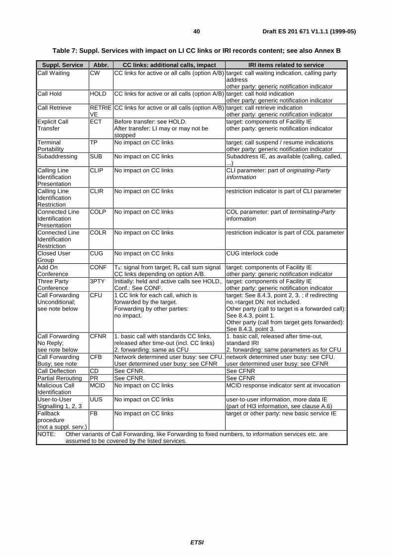
ETSI
Draft ES 201 671 V1.1.1 (1999-05)40
Table 7: Suppl. Services with impact on LI CC links or IRI records content; see also Annex B
Suppl. Service Abbr. CC links: additional calls, impact IRI items related to serviceCall Waiting CW CC links for active or all calls (option A/B) target: call waiting indication, calling party
addressother party: generic notification indicator
Call Hold HOLD CC links for active or all calls (option A/B) target: call hold indicationother party: generic notification indicator
Call Retrieve RETRIEVE
CC links for active or all calls (option A/B) target: call retrieve indicationother party: generic notification indicator
Explicit CallTransfer
ECT Before transfer: see HOLD.After transfer: LI may or may not bestopped
target: components of Facility IEother party: generic notification indicator
TerminalPortability
TP No impact on CC links target: call suspend / resume indicationsother party: generic notification indicator
Subaddressing SUB No impact on CC links Subaddress IE, as available (calling, called,...)
Calling LineIdentificationPresentation
CLIP No impact on CC links CLI parameter: part of originating-Partyinformation
Calling LineIdentificationRestriction
CLIR No impact on CC links restriction indicator is part of CLI parameter
Connected LineIdentificationPresentation
COLP No impact on CC links COL parameter: part of terminating-Partyinformation
Connected LineIdentificationRestriction
COLR No impact on CC links restriction indicator is part of COL parameter
Closed UserGroup
CUG No impact on CC links CUG interlock code
Add OnConference
CONF TX: signal from target; Rx call sum signalCC links depending on option A/B.
target: components of Facility IEother party: generic notification indicator
Three PartyConference
3PTY Initially: held and active calls see HOLD,.Conf.: See CONF.
target: components of Facility IEother party: generic notification indicator
Call ForwardingUnconditional;see note below
CFU 1 CC link for each call, which isforwarded by the target.Forwarding by other parties:no impact.
target: See 8.4.3, point 2, 3. ; if redirectingno.=target DN: not included.Other party (call to target is a forwarded call):See 8.4.3, point 1.Other party (call from target gets forwarded):See 8.4.3, point 3.
Call ForwardingNo Reply;see note below
CFNR 1. basic call with standards CC links,released after time-out (incl. CC links)2. forwarding: same as CFU
1. basic call, released after time-out,standard IRI2. forwarding: same parameters as for CFU
Call ForwardingBusy; see note
CFB Network determined user busy: see CFU.User determined user busy: see CFNR
network determined user busy: see CFU.user determined user busy: see CFNR
Call Deflection CD See CFNR. See CFNRPartial Rerouting PR See CFNR. See CFNRMalicious CallIdentification
MCID No impact on CC links MCID response indicator sent at invocation
User-to-UserSignalling 1, 2, 3
UUS No impact on CC links user-to-user information, more data IE(part of HI3 information, see clause A.6)
Fallbackprocedure(not a suppl. serv.)
FB No impact on CC links target or other party: new basic service IE
NOTE: Other variants of Call Forwarding, like Forwarding to fixed numbers, to information services etc. areassumed to be covered by the listed services.
ETSI
Draft ES 201 671 V1.1.1 (1999-05)41
11 Performance & quality
11.1 TimingAs a general principle, within a telecommunication system, intercept related information (IRI), if buffered, should bebuffered for as short a time as possible.
NOTE: If the transmission of intercept related information fails, it may be buffered or lost.
11.2 QualityThe quality of service associated with the result of interception should be (at least) equal to the quality of service of theoriginal content of communication.
12 Exception handling
12.1 Failure of CC linksIf a CC link cannot be set up, a certain number of repeat attempts during a certain period of time shall be made.
NOTE: Typical values are 3 tries during 10 seconds.
In case of a delay or total failure to transmit the content of communication, the following network depending optionsexist:
1) The target call is handled fully independent of the CC link, the CC information gets lost.
2) The target call set up is delayed, until the CC link is available; the delay is limited, if the limit is exceeded, thetarget call is set up.
12.2 Failure of ROSE protocol stackFor further study.
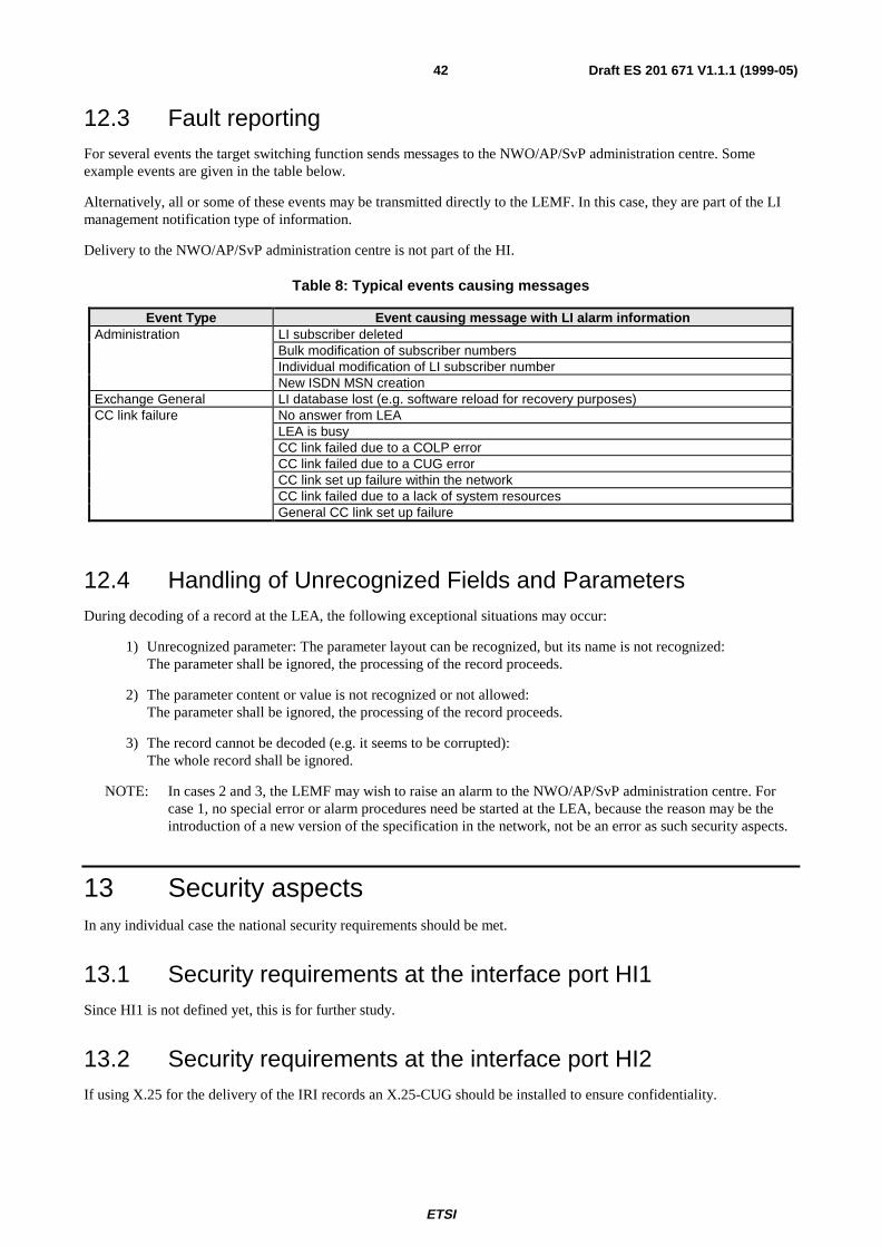
ETSI
Draft ES 201 671 V1.1.1 (1999-05)42
12.3 Fault reportingFor several events the target switching function sends messages to the NWO/AP/SvP administration centre. Someexample events are given in the table below.
Alternatively, all or some of these events may be transmitted directly to the LEMF. In this case, they are part of the LImanagement notification type of information.
Delivery to the NWO/AP/SvP administration centre is not part of the HI.
Table 8: Typical events causing messages
Event Type Event causing message with LI alarm informationAdministration LI subscriber deleted
Bulk modification of subscriber numbersIndividual modification of LI subscriber numberNew ISDN MSN creation
Exchange General LI database lost (e.g. software reload for recovery purposes)CC link failure No answer from LEA
LEA is busyCC link failed due to a COLP errorCC link failed due to a CUG errorCC link set up failure within the networkCC link failed due to a lack of system resourcesGeneral CC link set up failure
12.4 Handling of Unrecognized Fields and ParametersDuring decoding of a record at the LEA, the following exceptional situations may occur:
1) Unrecognized parameter: The parameter layout can be recognized, but its name is not recognized:The parameter shall be ignored, the processing of the record proceeds.
2) The parameter content or value is not recognized or not allowed:The parameter shall be ignored, the processing of the record proceeds.
3) The record cannot be decoded (e.g. it seems to be corrupted):The whole record shall be ignored.
NOTE: In cases 2 and 3, the LEMF may wish to raise an alarm to the NWO/AP/SvP administration centre. Forcase 1, no special error or alarm procedures need be started at the LEA, because the reason may be theintroduction of a new version of the specification in the network, not be an error as such security aspects.
13 Security aspectsIn any individual case the national security requirements should be met.
13.1 Security requirements at the interface port HI1Since HI1 is not defined yet, this is for further study.
13.2 Security requirements at the interface port HI2If using X.25 for the delivery of the IRI records an X.25-CUG should be installed to ensure confidentiality.
ETSI
Draft ES 201 671 V1.1.1 (1999-05)43
13.3 Security requirements at the interface port HI3The process of access verification and additional (optional) authentication between the MF and the LEMF shall notdelay the set up of the CC.
For the protection and access verification of the content of communication delivery call the ISDN supplementaryservices CLIP, COLP and CUG shall be used.
Generally any authentication shall be processed before the setup of the CC links between the MF and the LEMF iscompleted. If this is technically not feasible the authentication may be processed after completion of the CC connectionin parallel to the existing connection.
13.3.1 LI access verification
The supplementary service CLIP shall be used to check for the correct origin of the delivery call.
NOTE: When using CLIP, the supplementary service CLIR must not be used.
The supplementary service COLP shall be used to ensure that only the intended terminal on the LEA’s side acceptsincoming calls from the handover interface (HI).
To ensure access verification the following two checks shall be performed:
• check of calling-line identification presentation (CLIP) at the LEMF; and
• check of connected-line identification presentation (COLP) at the handover interface (HI).
13.3.2 Access protection
In order to prevent faulty connections to the LEA, the CC links may be set up as CUG calls.
In this case, the following settings of the CUG parameters should be used:
• Incoming Access: not allowed;
• Outgoing Access: not allowed;
• Incoming calls barred within a CUG: no;
• Outgoing calls barred within a CUG: yes.
13.3.3 Authentication
In addition to the minimum access verification mechanisms described above, optional authentication mechanismsaccording to the standard series ISO 9798 "Information technology - Entity authentication - parts 1 to 5" may be used.
These mechanisms shall only be used in addition to the access verification and protection mechanisms.
14 Quantitative aspectsSee [2]. The number of targets based on a percentage of subscribers should be provided at a national level together withan indication as to the expected usage.
ETSI
Draft ES 201 671 V1.1.1 (1999-05)44
Annex A (normative):Operation for sending of data across the HI interfaceThis annex specifies the coding details at the handover interface HI for all data records, which may be sent from theNWO/AP/SvP's equipment to the LEMF, across HI.
At the 3 handover interface ports, the following data records may be present:
• Interface port HI1: Interception configuration information (ICI) records;
• Interface port HI2: Interception related information (IRI) records;
• Interface port HI3: records containing message-based user information.
The detailed coding specification for these types of information is contained in this annex, including suffient details for aconsistent implementation in the NWO/AP/SvP's equipment and the LEMF.
A.1 Syntax definitionsThe transferred information and messages are encoded to be binary compatible with [33] (Abstract Syntax Notation One(ASN.1)) and [34] (Basic Encoding Rules (BER)).
These recommendations use precise definitions of the words type, class, value, and parameter. Those definitions areparaphrased below for clarity.
A type, in the context of the abstract syntax or transfer syntax, is a set of all possible values. For example, an INTEGERis a type for all negative and positive integers.
A class, in the context of the abstract syntax or transfer syntax, is a one of four possible domains for uniquely defining atype. The classes defined by ASN.1 and BER are: UNIVERSAL, APPLICATION, CONTEXT, and PRIVATE.
The UNIVERSAL class is reserved for international standards such as [33] and [34]. Most parameter type identifiers inthe HI ROSE operations are encoded as CONTEXT specific class. Users of the protocol may extend the syntax withPRIVATE class parameters without conflict with the present document, but risk conflict with other users’ extensions.APPLICATION class parameters are reserved for future extensions.
A value is a particular instance of a type. For example, five (5) is a possible value of the type INTEGER.
A parameter in the present document is a particular instance of the transfer syntax to transport a value consisting of a tagto identify the parameter type, a length to specify the number of octets in the value, and the value.
In the BER a tag (a particular type and class identifier) may either be a primitive or a constructor. A primitive is a pre-defined type (of class UNIVERSAL) and a constructor consists of other types (primitives or other constructors). Aconstructor type may either be IMPLICIT or EXPLICIT. An IMPLICIT type is encoded with the constructor identifieralone. Both ends of a communication must understand the underlying structure of the IMPLICIT types. EXPLICIT typesare encoded with the identifiers of all the contained types. For example, an IMPLICIT Number of type INTEGER wouldbe tagged only with the Number tag, where an EXPLICIT number of type INTEGER would have the INTEGER tagwithin the Number tag. The present document uses IMPLICIT tagging for more compact message encoding.
For the coding of the value part of each parameter the general rule is to use a widely use a standardized format when itexists (ISUP, DSS1, MAP, …).
As a large part of the information exchanged between the user’s may be transmitted within ISUP/DSS1 signalling, theusing of the coding defined for this signalling guarantee the integrity of the information provided to the LEMF and theevolution of the interface. For example if new values are used within existing ISUP parameters, this new values shall betransmitted transparently toward the LEMF.
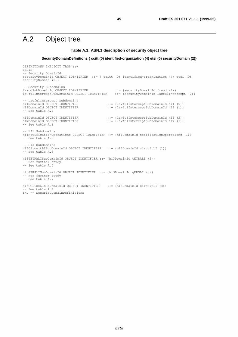
ETSI
Draft ES 201 671 V1.1.1 (1999-05)45
A.2 Object treeTable A.1: ASN.1 description of security object tree
SecurityDomainDefinitions { ccitt (0) identified-organization (4) etsi (0) securityDomain (2)}
DEFINITIONS IMPLICIT TAGS ::=BEGIN-- Security DomainIdsecurityDomainId OBJECT IDENTIFIER ::= { ccitt (0) identified-organization (4) etsi (0)securityDomain (2)}
-- Security SubdomainsfraudSubDomainId OBJECT IDENTIFIER ::= {securityDomainId fraud (1)}lawfulInterceptSubDomainId OBJECT IDENTIFIER ::= {securityDomainId lawfulIntercept (2)}
-- LawfulIntercept Subdomainshi1DomainId OBJECT IDENTIFIER ::= {lawfulInterceptSubDomainId hi1 (0)}hi2DomainId OBJECT IDENTIFIER ::= {lawfulInterceptSubDomainId hi2 (1)}-- See table A.4
hi3DomainId OBJECT IDENTIFIER ::= {lawfulInterceptSubDomainId hi3 (2)}himDomainId OBJECT IDENTIFIER ::= {lawfulInterceptSubDomainId him (3)}-- See table A.2
-- HI1 Subdomainshi1NotificationOperations OBJECT IDENTIFIER ::= {hi1DomainId notificationOperations (1)}-- See table A.3
-- HI3 Subdomainshi3CircuitLISubDomainId OBJECT IDENTIFIER ::= {hi3DomainId circuitLI (1)}-- See table A.5
hi3TETRALISubDomainId OBJECT IDENTIFIER ::= {hi3DomainId tETRALI (2)}-- For further study-- See table A.6
hi3GPRSLISubDomainId OBJECT IDENTIFIER ::= {hi3DomainId gPRSLI (3)}-- For further study-- See table A.7
hi3CCLinkLISubDomainId OBJECT IDENTIFIER ::= {hi3DomainId circuitLI (4)}-- See table A.8END -- SecurityDomainDefinitions
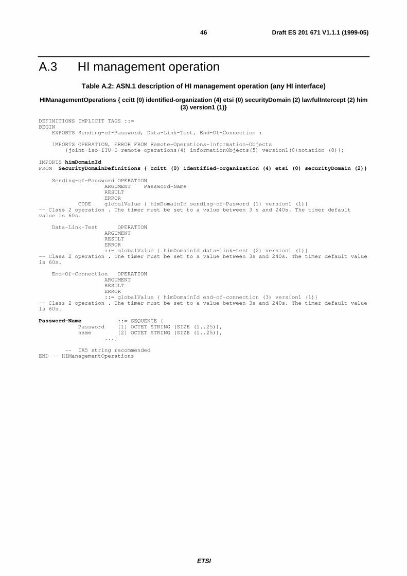
ETSI
Draft ES 201 671 V1.1.1 (1999-05)46
A.3 HI management operationTable A.2: ASN.1 description of HI management operation (any HI interface)
HIManagementOperations { ccitt (0) identified-organization (4) etsi (0) securityDomain (2) lawfulIntercept (2) him(3) version1 (1)}
DEFINITIONS IMPLICIT TAGS ::=BEGIN
EXPORTS Sending-of-Password, Data-Link-Test, End-Of-Connection ;
IMPORTS OPERATION, ERROR FROM Remote-Operations-Information-Objects{joint-iso-ITU-T remote-operations(4) informationObjects(5) version1(0)notation (0)};
IMPORTS himDomainIdFROM SecurityDomainDefinitions { ccitt (0) identified-organization (4) etsi (0) securityDomain (2)}
Sending-of-Password OPERATIONARGUMENT Password-NameRESULTERROR
CODE globalValue { himDomainId sending-of-Pasword (1) version1 (1)}-- Class 2 operation . The timer must be set to a value between 3 s and 240s. The timer defaultvalue is 60s.
Data-Link-Test OPERATIONARGUMENTRESULTERROR::= globalValue { himDomainId data-link-test (2) version1 (1)}
-- Class 2 operation . The timer must be set to a value between 3s and 240s. The timer default valueis 60s.
End-Of-Connection OPERATIONARGUMENTRESULTERROR::= globalValue { himDomainId end-of-connection (3) version1 (1)}
-- Class 2 operation . The timer must be set to a value between 3s and 240s. The timer default valueis 60s.
Password-Name ::= SEQUENCE {Password [1] OCTET STRING (SIZE (1..25)),name [2] OCTET STRING (SIZE (1..25)),
...}
-- IA5 string recommendedEND -- HIManagementOperations
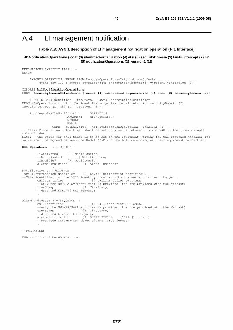
ETSI
Draft ES 201 671 V1.1.1 (1999-05)47
A.4 LI management notificationTable A.3: ASN.1 description of LI management notification operation (HI1 Interface)
HI1NotificationOperations { ccitt (0) identified-organization (4) etsi (0) securityDomain (2) lawfulIntercept (2) hi1(0) notificationOperations (1) version1 (1)}
DEFINITIONS IMPLICIT TAGS ::=BEGIN
IMPORTS OPERATION, ERROR FROM Remote-Operations-Information-Objects{joint-iso-ITU-T remote-operations(4) informationObjects(5) version1(0)notation (0)};
IMPORTS hi1NotificationOperationsFROM SecurityDomainDefinitions { ccitt (0) identified-organization (4) etsi (0) securityDomain (2)}
IMPORTS CallIdentifier, TimeStamp, LawfulInterceptionIdentifierFROM HI2Operations { ccitt (0) identified-organization (4) etsi (0) securityDomain (2)lawfulIntercept (2) hi2 (1) version1 (1)};
Sending-of-HI1-Notification OPERATIONARGUMENT HI1-OperationRESULTERROR
CODE globalValue { hi1NotificationOperations version1 (1)}-- Class 2 operation . The timer shall be set to a value between 3 s and 240 s. The timer defaultvalue is 60s.Note: The value for this timer is to be set on the equipment waiting for the returned message; itsvalue shall be agreed between the NWO/AP/SvP and the LEA, depending on their equipment properties.
HI1-Operation ::= CHOICE {
liActivated [1] Notification,liDeactivated [2] Notification,liModified [3] Notification,alarms-indicator [4] Alarm-Indicator
}Notification ::= SEQUENCE {lawfulInterceptionIdentifier [1] LawfulInterceptionIdentifier ,--This identifier is the LIID identity provided with the warrant for each target .
callIdentifier [2] CallIdentifier OPTIONAL,--only the NWO/PA/SvPIdentifier is provided (the one provided with the Warrant)timeStamp [3] TimeStamp,--date and time of the report.)...}
Alarm-Indicator ::= SEQUENCE {callIdentifier [1] CallIdentifier OPTIONAL,--only the NWO/PA/SvPIdentifier is provided (the one provided with the Warrant)timeStamp [2] TimeStamp,--date and time of the report.alarm-information [3] OCTET STRING (SIZE (1 .. 25)),--Provides information about alarms (free format)...}
--PARAMETERS
END -- H1CircuitDataOperations
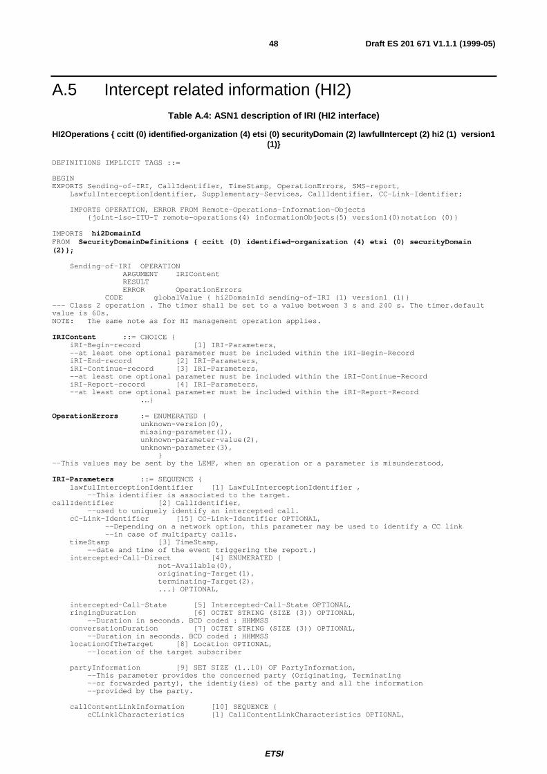
ETSI
Draft ES 201 671 V1.1.1 (1999-05)48
A.5 Intercept related information (HI2)Table A.4: ASN1 description of IRI (HI2 interface)
HI2Operations { ccitt (0) identified-organization (4) etsi (0) securityDomain (2) lawfulIntercept (2) hi2 (1) version1(1)}
DEFINITIONS IMPLICIT TAGS ::=
BEGINEXPORTS Sending-of-IRI, CallIdentifier, TimeStamp, OperationErrors, SMS-report,
LawfulInterceptionIdentifier, Supplementary-Services, CallIdentifier, CC-Link-Identifier;
IMPORTS OPERATION, ERROR FROM Remote-Operations-Information-Objects{joint-iso-ITU-T remote-operations(4) informationObjects(5) version1(0)notation (0)}
IMPORTS hi2DomainIdFROM SecurityDomainDefinitions { ccitt (0) identified-organization (4) etsi (0) securityDomain(2)};
Sending-of-IRI OPERATIONARGUMENT IRIContentRESULTERROR OperationErrors
CODE globalValue { hi2DomainId sending-of-IRI (1) version1 (1)}--- Class 2 operation . The timer shall be set to a value between 3 s and 240 s. The timer.defaultvalue is 60s.NOTE: The same note as for HI management operation applies.
IRIContent ::= CHOICE {iRI-Begin-record [1] IRI-Parameters,--at least one optional parameter must be included within the iRI-Begin-RecordiRI-End-record [2] IRI-Parameters,iRI-Continue-record [3] IRI-Parameters,--at least one optional parameter must be included within the iRI-Continue-RecordiRI-Report-record [4] IRI-Parameters,--at least one optional parameter must be included within the iRI-Report-Record
.…}
OperationErrors := ENUMERATED {unknown-version(0),missing-parameter(1),unknown-parameter-value(2),unknown-parameter(3), }
--This values may be sent by the LEMF, when an operation or a parameter is misunderstood,
IRI-Parameters ::= SEQUENCE {lawfulInterceptionIdentifier [1] LawfulInterceptionIdentifier ,
--This identifier is associated to the target.callIdentifier [2] CallIdentifier,
--used to uniquely identify an intercepted call.cC-Link-Identifier [15] CC-Link-Identifier OPTIONAL,
--Depending on a network option, this parameter may be used to identify a CC link--in case of multiparty calls.
timeStamp [3] TimeStamp,--date and time of the event triggering the report.)
intercepted-Call-Direct [4] ENUMERATED {not-Available(0),originating-Target(1),terminating-Target(2),...} OPTIONAL,
intercepted-Call-State [5] Intercepted-Call-State OPTIONAL,ringingDuration [6] OCTET STRING (SIZE (3)) OPTIONAL,
--Duration in seconds. BCD coded : HHMMSSconversationDuration [7] OCTET STRING (SIZE (3)) OPTIONAL,
--Duration in seconds. BCD coded : HHMMSSlocationOfTheTarget [8] Location OPTIONAL,
--location of the target subscriber
partyInformation [9] SET SIZE (1..10) OF PartyInformation,--This parameter provides the concerned party (Originating, Terminating--or forwarded party), the identiy(ies) of the party and all the information--provided by the party.
callContentLinkInformation [10] SEQUENCE {cCLink1Characteristics [1] CallContentLinkCharacteristics OPTIONAL,
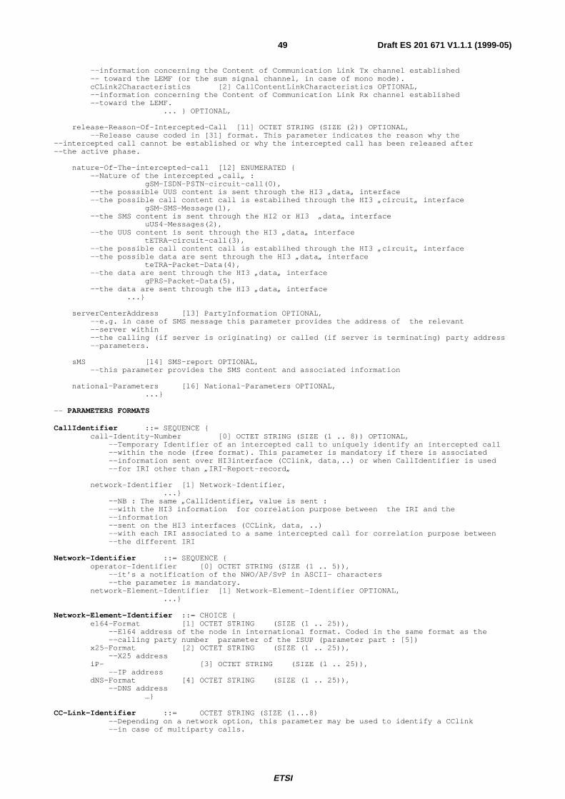
ETSI
Draft ES 201 671 V1.1.1 (1999-05)49
--information concerning the Content of Communication Link Tx channel established-- toward the LEMF (or the sum signal channel, in case of mono mode).cCLink2Characteristics [2] CallContentLinkCharacteristics OPTIONAL,--information concerning the Content of Communication Link Rx channel established--toward the LEMF.
... } OPTIONAL,
release-Reason-Of-Intercepted-Call [11] OCTET STRING (SIZE (2)) OPTIONAL,--Release cause coded in [31] format. This parameter indicates the reason why the
--intercepted call cannot be established or why the intercepted call has been released after--the active phase.
nature-Of-The-intercepted-call [12] ENUMERATED {--Nature of the intercepted „call„ :
gSM-ISDN-PSTN-circuit-call(0),--the posssible UUS content is sent through the HI3 „data„ interface--the possible call content call is establihed through the HI3 „circuit„ interface
gSM-SMS-Message(1),--the SMS content is sent through the HI2 or HI3 „data„ interface
uUS4-Messages(2),--the UUS content is sent through the HI3 „data„ interface
tETRA-circuit-call(3),--the possible call content call is establihed through the HI3 „circuit„ interface--the possible data are sent through the HI3 „data„ interface
teTRA-Packet-Data(4),--the data are sent through the HI3 „data„ interface
gPRS-Packet-Data(5),--the data are sent through the HI3 „data„ interface
...}
serverCenterAddress [13] PartyInformation OPTIONAL,--e.g. in case of SMS message this parameter provides the address of the relevant--server within--the calling (if server is originating) or called (if server is terminating) party address--parameters.
sMS [14] SMS-report OPTIONAL,--this parameter provides the SMS content and associated information
national-Parameters [16] National-Parameters OPTIONAL,...}
-- PARAMETERS FORMATS
CallIdentifier ::= SEQUENCE {call-Identity-Number [0] OCTET STRING (SIZE (1 .. 8)) OPTIONAL,
--Temporary Identifier of an intercepted call to uniquely identify an intercepted call--within the node (free format). This parameter is mandatory if there is associated--information sent over HI3interface (CClink, data,..) or when CallIdentifier is used--for IRI other than „IRI-Report-record„
network-Identifier [1] Network-Identifier,...}
--NB : The same „CallIdentifier„ value is sent :--with the HI3 information for correlation purpose between the IRI and the--information--sent on the HI3 interfaces (CCLink, data, ..)--with each IRI associated to a same intercepted call for correlation purpose between--the different IRI
Network-Identifier ::= SEQUENCE {operator-Identifier [0] OCTET STRING (SIZE (1 .. 5)),
--it’s a notification of the NWO/AP/SvP in ASCII- characters--the parameter is mandatory.
network-Element-Identifier [1] Network-Element-Identifier OPTIONAL,...}
Network-Element-Identifier ::= CHOICE {e164-Format [1] OCTET STRING (SIZE (1 .. 25)),
--E164 address of the node in international format. Coded in the same format as the--calling party number parameter of the ISUP (parameter part : [5])
x25-Format [2] OCTET STRING (SIZE (1 .. 25)),--X25 address
iP- [3] OCTET STRING (SIZE (1 .. 25)),--IP address
dNS-Format [4] OCTET STRING (SIZE (1 .. 25)),--DNS address
…}
CC-Link-Identifier ::= OCTET STRING (SIZE (1...8)--Depending on a network option, this parameter may be used to identify a CClink--in case of multiparty calls.
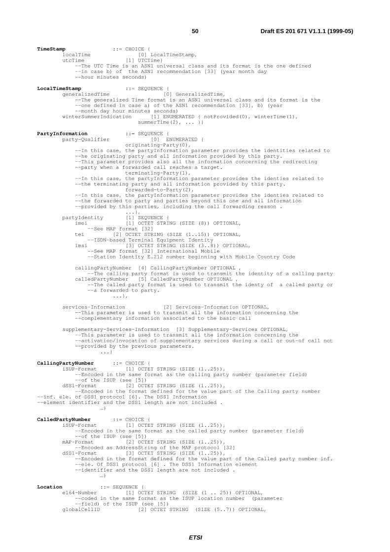
ETSI
Draft ES 201 671 V1.1.1 (1999-05)50
TimeStamp ::= CHOICE {localTime [0] LocalTimeStamp,utcTime [1] UTCTime}
--The UTC Time is an ASN1 universal class and its format is the one defined--in case b) of the ASN1 recommendation [33] (year month day--hour minutes seconds)
LocalTimeStamp ::= SEQUENCE {generalizedTime [0] GeneralizedTime,
--The generalized Time format is an ASN1 universal class and its format is the--one defined in case a) of the ASN1 recommendation [33], b) (year--month day hour minutes seconds)
winterSummerIndication [1] ENUMERATED { notProvided(0), winterTime(1),summerTime(2), ... }}
PartyInformation ::= SEQUENCE {party-Qualifier [0] ENUMERATED {
originating-Party(0),--In this case, the partyInformation parameter provides the identities related to--he originating party and all information provided by this party.--This parameter provides also all the information concerning the redirecting--party when a forwarded call reaches a target.
terminating-Party(1),--In this case, the partyInformation parameter provides the identies related to--the terminating party and all information provided by this party.
forwarded-to-Party(2),--In this case, the partyInformation parameter provides the identies related to--the forwarded to party and parties beyond this one and all information--provided by this parties, including the call forwarding reason .
...},partyIdentity [1] SEQUENCE {
imei [1] OCTET STRING (SIZE (8)) OPTIONAL,--See MAP format [32]
tei [2] OCTET STRING (SIZE (1..15)) OPTIONAL,--ISDN-based Terminal Equipment Identity
imsi [3] OCTET STRING (SIZE (3..8)) OPTIONAL,--See MAP format [32] International Mobile--Station Identity E.212 number beginning with Mobile Country Code
callingPartyNumber [4] CallingPartyNumber OPTIONAL ,--The calling party format is used to transmit the identity of a calling party
calledPartyNumber [5] CalledPartyNumber OPTIONAL ,--The called party format is used to transmit the identy of a called party or--a forwarded to party.
...},
services-Information [2] Services-Information OPTIONAL,--This parameter is used to transmit all the information concerning the--complementary information associated to the basic call
supplementary-Services-Information [3] Supplementary-Services OPTIONAL,--This parameter is used to transmit all the information concerning the--activation/invocation of supplementary services during a call or out-of call not--provided by the previous parameters.
...}
CallingPartyNumber ::= CHOICE {iSUP-Format [1] OCTET STRING (SIZE (1..25)),
--Encoded in the same format as the calling party number (parameter field)--of the ISUP (see [5])
dSS1-Format [2] OCTET STRING (SIZE (1..25)),--Encoded in the format defined for the value part of the Calling party number
--inf. ele. of DSS1 protocol [6]. The DSS1 Information--element identifier and the DSS1 length are not included .
…}
CalledPartyNumber ::= CHOICE {iSUP-Format [1] OCTET STRING (SIZE (1..25)),
--Encoded in the same format as the called party number (parameter field)--of the ISUP (see [5])
mAP-Format [2] OCTET STRING (SIZE (1..25)),--Encoded as AddressString of the MAP protocol [32]
dSS1-Format [3] OCTET STRING (SIZE (1..25)),--Encoded in the format defined for the value part of the Called party number inf.--ele. Of DSS1 protocol [6] . The DSS1 Information element--identifier and the DSS1 length are not included .
…}
Location ::= SEQUENCE {e164-Number [1] OCTET STRING (SIZE (1 .. 25)) OPTIONAL,
--coded in the same format as the ISUP location number (parameter--field) of the ISUP (see [5])
globalCellID [2] OCTET STRING (SIZE (5..7)) OPTIONAL,
ETSI
Draft ES 201 671 V1.1.1 (1999-05)51
--see MAP format (see [32])tetraLocation [3] TetraLocation OPTIONAL,
…}
TetraLocation ::= CHOICE {ms-Loc [1] SEQUENCE {
mcc [1] INTEGER (0...1023),--16 bits ETS [40]
mnc [2] INTEGER (0...1023),--14 bits ETS [40]
lai [3] INTEGER (0...65535),--14 bits ETS [40]
ci [4] INTEGER OPTIONAL},
-- (to be completed)ls-Loc [2] INTEGER
-- (to be confirmed and completed)}
CallContentLinkCharacteristics ::= SEQUENCE {cCLink-State [1] CCLink-State OPTIONAL,
--current state of the CCLinkrelease-Time [2] TimeStamp OPTIONAL,
--date and time of the release of the Call Content Link.release-Reason [3] OCTET STRING (SIZE(2)) OPTIONAL,
--Release cause coded in [31] format.lEMF-Address [4] CalledPartyNumber OPTIONAL,
--Directory number used to route the call toward the LEMF....}
CCLink-State ::= ENUMERATED {setUPInProcess(1),callActive(2),callReleased(3),lack-of-resource(4),
--the lack-of-resource state is sent when a CC Link cannot--be established because of lack of resource at the MF level
...}
Intercepted-Call-State ::= ENUMERATED {idle(1),
--When the intercept call is released, the state is IDLE and the reason is provided--by the release-Reason-Of-Intercepted-Call parameter.
setUpInProcees(2),--The setup of the call is in process
connected (3),--The answer has been received
...}
Services-Information ::= SEQUENCE {iSUP-parameters [1] ISUP-parameters,dSS1-parameters-codeset-0 [2] DSS1-parameters-codeset-0 OPTIONAL,
...}
ISUP-parameters ::= SET SIZE (1..256) OF OCTET STRING (SIZE (1..256))--each «OCTET STRING» contains one additional ISUP parameter TLV coded not already defined in--the previous parameters. The Tag value is the one given in Recommendation [5] .--The Length and the Value are coded in accordance with the parameter definition in recommendation--[5]. Hereafter are listed the main parameters. However other parameters may be added :
--Transmission medium requirement : format defined in recommendation [5]--This parameter can be provided with the «Party Information» of the „calling party„
--Transmission medium requirement prime : format defined in recommendation [5]--This parameter can be provided with the «Party Information» of the „calling party„
DSS1-parameters-codeset-0 ::= SET SIZE (1..256) OF OCTET STRING (SIZE (1..256))--each «OCTET STRING» contains one DSS1 parameter of the codeset 0. The parameter is coded as--described in recommendation [6] (The DSS1 Information element identifier and the DSS1 length--are included). Hereafter are listed the main parameters (However other parameters may be added) :
--Bearer capability : this parameter may be repeated. Format defined in recommendation [6]--This parameter can be provided with the «Party Information» of the «calling party»,--«called party» or «forwarded to party».
--High Layer Compatibility : this parameter may be repeated. Format defined in-- recommendation [6].--This parameter can be provided with the «Party Information» of the «calling party»,--«called party» or « forwarded to party».
--Low Layer capability : this parameter may be repeated. Format defined in-- recommendation [6].--This parameter can be provided with the «Party Information» of the «calling party»,
ETSI
Draft ES 201 671 V1.1.1 (1999-05)52
--«called party» or «forwarded to party».
Supplementary-Services ::= SEQUENCE {standard-Supplementary-Services [1] Standard-Supplementary-Services OPTIONAL ,non-Standard-Supplementary-Services [2] Non-Standard-Supplementary-Services OPTIONAL,other-Services [3] Other-Services OPTIONAL,
...}
Standard-Supplementary-Services ::= SEQUENCE {iSUP-SS-parameters [1] ISUP-SS-parameters,dSS1-SS-parameters-codeset-0 [2] DSS1-SS-parameters-codeset-0 OPTIONAL,dSS1-SS-parameters-codeset-4 [3] DSS1-SS-parameters-codeset-4 OPTIONAL,dSS1-SS-parameters-codeset-5 [4] DSS1-SS-parameters-codeset-5 OPTIONAL,dSS1-SS-parameters-codeset-6 [5] DSS1-SS-parameters-codeset-6 OPTIONAL,dSS1-SS-parameters-codeset-7 [6] DSS1-SS-parameters-codeset-7 OPTIONAL,dSS1-SS-Invoke-components [7] DSS1-SS-Invoke-Components OPTIONAL,mAP-SS-Parameters [8] MAP-SS-Parameters OPTIONAL,mAP-SS-Invoke-Components [9] MAP-SS-Invoke-Components OPTIONAL,
...}
Non-Standard-Supplementary-Services ::= SET SIZE (1..20) OF CHOICE {simpleIndication [1] SimpleIndication,sciData [2] SciDataMode,
…}
Other-Services ::= SET SIZE (1..50) OF OCTET STRING (SIZE (1..256))--reference manufacturer manuals
ISUP-SS-parameters ::= SET SIZE (1..256) OF OCTET STRING (SIZE (1..256))--each «OCTET STRING» contains one additional ISUP parameter TLV coded not already defined in--the previous parameters. The Tag value is the one given in recommendation [5] .--The Length and the Value are coded in accordance with the parameter definition in recommendation-- [5]. Hereafter are listed the main parameters. However other parameters may be added :
--Connected Number : format defined in recommendation [5]--This parameter can be provided with the « Party Information» of the--«called party» or «forwarded to party»
--RedirectingNumber : format defined in recommendation [5]--This parameter can be provided with the « Party Information» of the «originating party»
--Original Called Party Number : format defined in recommendation [5]--This parameter can be provided with the « Party Information» of the--«originating party»..
--Redirection information : format defined in recommendation [5]--This parameter can be provided with the «Party Information» of the--«originating party» , «forwarded to party» or/and «Terminating party»
--Redirection Number : format defined in recommendation [5]--This parameter can be provided with the «Party Information» of the--«forwarded to party» or «Terminating party»
--Call diversion information: format defined in recommendation [5]--This parameter can be provided with the «Party Information» of the--«forwarded to party» or «Terminating party» .
--Generic Number : format defined in recommendation [5]--This parameter can be provided with the «Party Information»of the--«calling party», «called party» or «forwarded to party».--This parameters are used to transmit additional identities (additional ,calling party--number, additional called number, …)
--Generic Notification : format defined in recommendation [5]--This parameter may be provided with the «Party Information» of the--«calling party», «called party» or «forwarded to party».--This parameters transmit the notification to the other part of the call of the supplementary--services activated or invoked by a subscriber during the call.
--CUG Interlock Code : format defined in recommendation [5]--This parameter can be provided with the «Party Information» of the--«calling party».
DSS1-SS-parameters-codeset-0 ::= SET SIZE (1..256) OF OCTET STRING (SIZE (1..256))--each «OCTET STRING» contains one DSS1 parameter of the codeset 0. The parameter is coded as--described in recommendation [6] (The DSS1 Information element identifier and the DSS1 length--are included). Hereafter are listed the main parameters (However other parameters may be added) :
--Calling Party Subaddress : Format defined in recommendation [6].--This parameter can be provided with the «Party Information» of the--«calling party».
--Called Party Subaddress : Format defined in recommendation [6].
ETSI
Draft ES 201 671 V1.1.1 (1999-05)53
--This parameter can be provided with the «Party Information» of the--«calling party», .
--Connected Subaddress. : Format defined in recommendation (see [14]).--This parameter can be provided with the «Party Information» of the--«called party» or «forwarded to party».
--Connected Number : Format defined in recommendation (see [14]).--This parameter can be provided with the «Party Information» of the--«called party» or «forwarded to party».
--Keypad facility : Format defined in recommendation [6].--This parameter can be provided with the «Party Information» of the--«calling party», «called party» or «forwarded to party».
DSS1-SS-parameters-codeset-4 ::= SET SIZE (1..256) OF OCTET STRING (SIZE (1..256))--each «OCTET STRING» contains one DSS1 parameter of the codeset 4. The parameter is coded as--described in the relevant recommendation .
DSS1-SS-parameters-codeset-5 ::= SET SIZE (1..256) OF OCTET STRING (SIZE (1..256))--each «OCTET STRING» contains one DSS1 parameter of the codeset 5. The parameter is coded as--described in the relevant national recommendation .
DSS1-SS-parameters-codeset-6 ::= SET SIZE (1..256) OF OCTET STRING (SIZE (1..256))--each «OCTET STRING» contains one DSS1 parameter of the codeset 6. The parameter is coded as--described in the relevant local network recommendation .
DSS1-SS-parameters-codeset-7 := SET SIZE (1..256) OF OCTET STRING (SIZE (1..256))--each «octet string» contains one DSS1 parameter of the codeset 7. The parameter is coded as--described in the relevant user specific recommendation .
DSS1-SS-Invoke-Components ::= SET SIZE (1..256) OF OCTET STRING (SIZE (1..256))--each «octet string» contains one DSS1 Invoke or Return Result component.--The invoke or return result component is coded as--described in the relevant DSS1 supplementary service recommendation.
--Invoke or Return Result component (BeginCONF) : reference [19]--Invoke or Return Result component (AddCONF) : reference [19]--Invoke or Return Result component (SplitCONF) : reference [19]--Invoke or Return Result component (DropCONF) : reference [19]--Invoke or Return Result component (IsolateCONF) : reference [19]--Invoke or Return Result component (ReattachCONF) : reference [19]--Invoke or Return Result component (PartyDISC) : reference [19]--Invoke or Return Result component (MCIDRequest) : reference [16]--Invoke or Return Result component (Begin3PTY) : reference [20]--Invoke or Return Result component (End3PTY) : reference [20]--Invoke or Return Result component (ECTExecute) : reference [25]--Invoke or Return Result component (ECTInform) : reference [25]--Invoke or Return Result component (ECTLinkIdRequest) : reference [25]--Invoke or Return Result component (ECTLoopTest) : reference [25]--Invoke or Return Result component (ExplicitECTExecute) : reference [25]--Invoke or Return Result component (ECT : RequestSubaddress) : reference [25]--Invoke or Return Result component (ECT : SubaddressTransfer) : reference [25]--Invoke or Return Result component (CF : ActivationDiversion) : reference [21]--Invoke or Return Result component (CF : DeactivationDiversion) : reference [21]--Invoke or Return Result component (CF : ActivationStatusNotification) : reference [21]--Invoke or Return Result component (CF : DeactivationStatusNotification) : reference [21]--Invoke or Return Result component (CF : InterrogationDiversion) : reference [21]--Invoke or Return Result component (CF : InterrogationServedUserNumber) : reference [21]--Invoke or Return Result component (CF : DiversionInformation) : reference [21]--Invoke or Return Result component (CF : CallDeflection) : reference [21]--Invoke or Return Result component (CF : CallRerouteing) : reference [21]--Invoke or Return Result component (CF : DivertingLegInformation1) : reference [21]--Invoke or Return Result component (CF : DivertingLegInformation2) : reference [21]--Invoke or Return Result component (CF : DivertingLegInformation3) : reference [21]--other invoke or return result components ...
MAP-SS-Invoke-Components ::= SET SIZE (1..256) OF OCTET STRING (SIZE (1..256))--each «octet string» contains one MAP Invoke or Return Result component.--The invoke or return result component is coded as--described in the relevant MAP supplementary service recommendation.
MAP-SS-Parameters ::= SET SIZE (1..256) OF OCTET STRING (SIZE (1..256))--each «octet string» contains one MAP Parameter. The parameter is coded as--described in the relevant MAP supplementary service recommendation.
SimpleIndication ::= ENUMERATED {call-Waiting-Indication(0),
--the target has received a call waiting indication for this calladd-conf-Indication(1),
--this call has been added to a conferencecall-on-hold-Indication(2),
--indication that this call is on holdretrieve-Indication(3),

ETSI
Draft ES 201 671 V1.1.1 (1999-05)54
--indication that this call has been retreivedsuspendIndication(4),
-- indication that this call has been suspendedresume-Indication(5),
-- indication that this call has been resumedanswer-Indication(6),
--indication that this call has been answered... }
SciDataMode ::= OCTET STRING (SIZE (1..256))
SMS-report ::= SEQUENCE {callIdentifier [1] CallIdentifier,
-- used to uniquely identify an intercepted call : the same used for the-- relevant IRI
timeStamp [2] TimeStamp,--date and time of the report. The format is--the one defined in case a) of the ASN1 recommendation [33].--(year month day hour minutes seconds)
sMS-Contents [3] SEQUENCE {initiator [1] ENUMERATED {
--party which sent the SMStarget(0),server(1),undefined-party(2),
... },transfer-status [2] ENUMERATED {
--the transfer of the SMS message succeedssucceed-transfer(0),not-succeed-transfer(1),undefined(2),
... } OPTIONAL,other-message [3] ENUMERATED {
--in case of terminating call, indicates if the server will send--other SMS
yes(0),no(1),undefined(2),
... } OPTIONAL,content [4] OCTET STRING (SIZE (1 .. 270)) ,
--Encoded in the format defined for the SMS mobile... }}
LawfulInterceptionIdentifier ::= OCTET STRING (SIZE (1..25))National-Parameters ::= SET SIZE (1..40) OF OCTET STRING (SIZE (1..256))--Content defined by national lawEND -- OF HI2Operations
ETSI
Draft ES 201 671 V1.1.1 (1999-05)55
A.6 User data packet transfer (HI3 interface)Table A.5: ASN.1 description of circuit_data transfer operation (HI3 interface)
HI3CircuitDataOperations { ccitt (0) identified-organization (4) etsi (0) securityDomain (2) lawfulIntercept (2) hi3(2) circuitLI (1) version1 (1)}
DEFINITIONS IMPLICIT TAGS ::=
--The following operations are used to transmit user data which can be exchanged via the DSS1, ISUPor--MAP signalling (e.g. UUS, SMS)BEGIN
IMPORTS OPERATION, ERROR FROM Remote-Operations-Information-Objects{joint-iso-ITU-T remote-operations(4) informationObjects(5) version1(0)notation (0)}
IMPORTS hi3CircuitLISubDomainIdFROM SecurityDomainDefinitions { ccitt (0) identified-organization (4) etsi (0) securityDomain (2)}
IMPORTS CallIdentifier, TimeStamp, OperationErrors, Supplementary-Services, SMS-reportFROM HI2Operations HI2Operations { ccitt (0) identified-organization (4) etsi (0)
securityDomain (2)lawfulIntercept (2) hi2 (1) version1 (1)} ;
Circuit-Call-related-Services OPERATIONARGUMENT Content-ReportRESULTERROR OperationErrors
CODE globalValue { hi3CircuitLISubDomainId circuit-Call-Serv (1) version1 (1)}--- Class 2 operation . The timer shall be set to a value between 3 s and 240 s. The timer defaultvalue is 60s.--NOTE: The same note as for HI management operation applies.
No-Circuit-Call-related-Services OPERATIONARGUMENT Content-ReportRESULTERROR OperationErrors
::= globalValue { hi3CircuitLISubDomainId no-Circuit-Call-Serv (2) version1 (1)}--Class 2 operation . The timer must be set to a value between 10s and 120s. The timer default valueis 60s.
Content-Report ::= SEQUENCE {callIdentifier [1] CallIdentifier,
--used to uniquely identify an intercepted call: the same as used for the relevant IRItimeStamp [2] TimeStamp,
initiator [3] ENUMERATED {originationg-party(0),terminating-party(1),forwarded-to-party(2),undefined-party(3),
... }OPTIONAL,content [4] Supplementary-Services OPTIONAL,
--UUI are encoded in the format defined for the User-to-user information parameter--of the ISUP protocol (see [5]).Only one UUI parameter is sent per message.
sMS-report [5] SMS-report OPTIONAL,... }
END -- HI3CircuitDataOperations
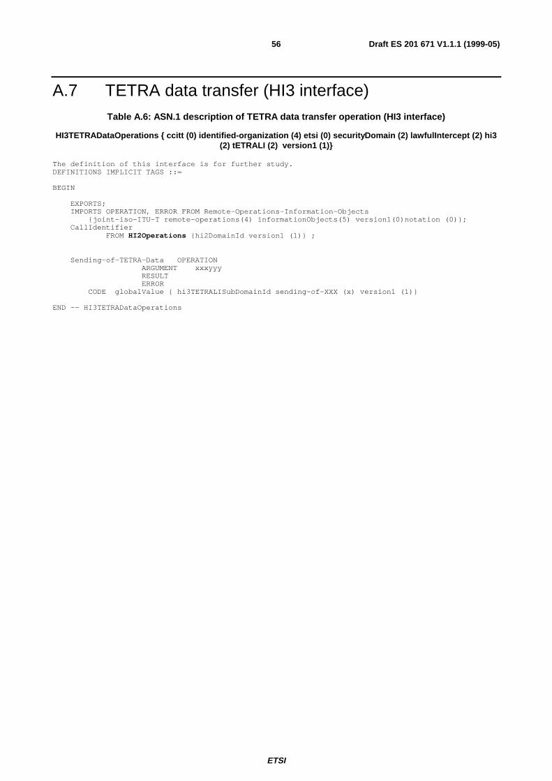
ETSI
Draft ES 201 671 V1.1.1 (1999-05)56
A.7 TETRA data transfer (HI3 interface)Table A.6: ASN.1 description of TETRA data transfer operation (HI3 interface)
HI3TETRADataOperations { ccitt (0) identified-organization (4) etsi (0) securityDomain (2) lawfulIntercept (2) hi3(2) tETRALI (2) version1 (1)}
The definition of this interface is for further study.DEFINITIONS IMPLICIT TAGS ::=
BEGIN
EXPORTS;IMPORTS OPERATION, ERROR FROM Remote-Operations-Information-Objects
{joint-iso-ITU-T remote-operations(4) informationObjects(5) version1(0)notation (0)};CallIdentifier
FROM HI2Operations {hi2DomainId version1 (1)} ;
Sending-of-TETRA-Data OPERATIONARGUMENT xxxyyyRESULTERROR
CODE globalValue { hi3TETRALISubDomainId sending-of-XXX (x) version1 (1)}
END -- HI3TETRADataOperations
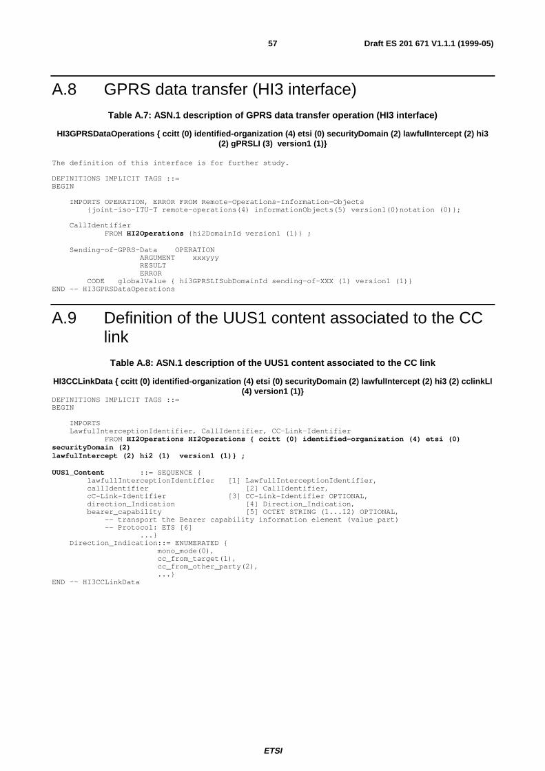
ETSI
Draft ES 201 671 V1.1.1 (1999-05)57
A.8 GPRS data transfer (HI3 interface)Table A.7: ASN.1 description of GPRS data transfer operation (HI3 interface)
HI3GPRSDataOperations { ccitt (0) identified-organization (4) etsi (0) securityDomain (2) lawfulIntercept (2) hi3(2) gPRSLI (3) version1 (1)}
The definition of this interface is for further study.
DEFINITIONS IMPLICIT TAGS ::=BEGIN
IMPORTS OPERATION, ERROR FROM Remote-Operations-Information-Objects{joint-iso-ITU-T remote-operations(4) informationObjects(5) version1(0)notation (0)};
CallIdentifierFROM HI2Operations {hi2DomainId version1 (1)} ;
Sending-of-GPRS-Data OPERATIONARGUMENT xxxyyyRESULTERROR
CODE globalValue { hi3GPRSLISubDomainId sending-of-XXX (1) version1 (1)}END -- HI3GPRSDataOperations
A.9 Definition of the UUS1 content associated to the CClink
Table A.8: ASN.1 description of the UUS1 content associated to the CC link
HI3CCLinkData { ccitt (0) identified-organization (4) etsi (0) securityDomain (2) lawfulIntercept (2) hi3 (2) cclinkLI(4) version1 (1)}
DEFINITIONS IMPLICIT TAGS ::=BEGIN
IMPORTSLawfulInterceptionIdentifier, CallIdentifier, CC-Link-Identifier
FROM HI2Operations HI2Operations { ccitt (0) identified-organization (4) etsi (0)securityDomain (2)lawfulIntercept (2) hi2 (1) version1 (1)} ;
UUS1_Content ::= SEQUENCE {lawfullInterceptionIdentifier [1] LawfullInterceptionIdentifier,callIdentifier [2] CallIdentifier,cC-Link-Identifier [3] CC-Link-Identifier OPTIONAL,direction_Indication [4] Direction_Indication,bearer_capability [5] OCTET STRING (1...12) OPTIONAL,
-- transport the Bearer capability information element (value part)-- Protocol: ETS [6]
...}Direction_Indication::= ENUMERATED {
mono_mode(0),cc_from_target(1),cc_from_other_party(2),...}
END -- HI3CCLinkData
ETSI
Draft ES 201 671 V1.1.1 (1999-05)58
Annex B (normative):Detailed procedures for supplementary services (circuitswitched)
B.1 Advice of Charge Services (AOC)No impact.
Advice of charge information is not included in IRI records.
B.2 Call Waiting
B.2.1 Call Waiting at target: CC linksIn case of option A "CC links for all calls", a CC link is set up for the waiting call, using the standard procedures forterminating calls. In case of option B "CC links for active calls", no CC link is set up for the waiting call, it is treatedlike a held call.
With respect to CC links, the same configurations as for Call Hold apply.
Procedure, when the target accepts the waiting call: See retrieve of a held call (clause B.3).
B.2.2 Call Waiting: IRI records
B.2.2.1 Target is served user
If Call Waiting is invoked at the target access by another (calling) party: The IRI-BEGIN record or a followingIRI-CONTINUE record for the waiting call shall contain the LI specific parameter call waiting indication.
B.2.2.2 Other party is served user
If Call Waiting is invoked at the other (called) party’s access: If a CW notification is received by the target’s switchingnode, it shall be included in an IRI-CONTINUE record; it may be a separate record, or the next record of the basic callsequence.
B.3 Call Hold/Retrieve
B.3.1 CC links for active and non-active calls (option A)If an active call is put on hold, its CC links shall stay intact; as an option, the signal from the held party is not switchedthrough to the LEMF.
If the target sets up a new call, while one call is on hold, this call is treated like a normal originating call, i.e. a new LIconfiguration (CC links, IRI records) is established.
ETSI
Draft ES 201 671 V1.1.1 (1999-05)59
B.3.2 Reuse of CC links for active calls (option B)If an active call is put on hold, its CC links shall not immediately be disconnected; as an option, the signal from the heldparty is not switched through to the LEMF.
If the target sets up a new call, or retrieves a previously held call, while one target call, which still owns CC links, is onhold, these CC links shall be used for the signals of the new active call.
B.3.3 IRI records
B.3.3.1 Invocation of Call Hold or Retrieve by target:
An IRI-CONTINUE record with the LI specific parameter hold indication or retrieve indication, respectively, shall besent.
B.3.3.2 Invocation of Hold or Retrieve by other parties:
An IRI-CONTINUE record with a call hold or retrieve notification shall be sent within an IRI-CONTINUE record, if ithas been received by the signalling protocol entity of the target call.
B.4 Explicit Call Transfer
B.4.1 Explicit Call Transfer, CC linkDuring the preparation phase of a transfer, the procedures for Call Hold / Retrieve are applicable.
If the served (transferring) user is the target, its original call is released. This terminates also the CC link, and causes anIRI-END record to be sent.
After transfer, two options exist:
a) For the transferred call, CC links (and IRI records) shall be generated, in principle like for a forwarded call(similar to procedures in subclause B.16.1, case b)).
b) The transferred call shall not be intercepted.
B.4.2 Explicit Call Transfer, IRI recordsIn addition to the basic or hold / retrieve / waiting call related records and parameters, during the reconfiguration of thecall, ECT-specific information at the target’s access is sent to the LEMF within IRI-CONTINUE records.
When the target leaves the call after transfer, an IRI-END record is sent, and the LI transaction is terminated. Optionsfor the new call, after transfer: see section above.
B.5 Calling Line Identification Presentation (IRI Records)
B.5.1 Call originated by target (target is served user)The standard CLI parameter of an originating target is not included as a supplementary service parameter in the IRIrecords.
If the target uses the two calling party number information elements delivery option (network option of the CLIPservice) to provide a user provided, not screened number, this number is included in the IRI-BEGIN record
ETSI
Draft ES 201 671 V1.1.1 (1999-05)60
(originating-Party information), as a generic number parameter. The network provided default number of the access is,as without this option, not included in an IRI record.
B.5.2 Call terminated at target (other party is served user)The CLI sent from the other party is included in the IRI-BEGIN record (originating-Party information), irrespective ofa restriction indication. An eventually received second number (case two number delivery option) is included in the IRIrecord as supplementary services information (Generic Number parameter).
B.6 Calling Line Identification Restriction (CLIR)For use by LI, the restriction is ignored, but copied within the CLI parameter to the IRI record.
B.7 Connected Line Identification Presentation (COLP)
B.7.1 Call terminated at target (target is served user)A connected number parameter received from the target shall be included in an IRI record (terminating-Partyinformation), if it is not equal to the target identity.
B.7.2 Call originated by target (other party is served user)If available, a connected number parameter as received from the other (terminating) party shall be included in an IRIrecord (terminating-Party information).
B.8 Connected Line Identification restriction (COLR)For use by LI, the restriction is ignored, but copied within the COL parameter to the IRI record.
B.9 Closed User Group (CUG)In case of a CUG call, the closed user group interlock code shall be included in an IRI.
B.10 Completion of Call to Busy Subscriber (CCBS)No impact.
The first call, which meets a (terminating) busy subscriber, and is released subsequently, is treated like a standard busycall, with no CCBS related IRI information.
The procedures for CCBS, until starting a new call attempt from the served user to the terminating user, including theCCBS recall, are not subject of LI.
ETSI
Draft ES 201 671 V1.1.1 (1999-05)61
B.11 Conference Call, Add-On (CONF)
B.11.1 Conference Calls, Add On: CC linksThe CC links carry the same bit stream as sent to / received from the target, that is, the Rx call contains the sum signal ofthe conference, the Tx call contains the signal from the target.
The general rules for multi party calls (subclause 10.4) apply also for the various possible states during a conference(isolate, split, ...). The call to the conference device as such is treated like a standard call. In case of a n-partyconference, there exist n+1 CC links in case of option "CC link for all calls", or just one CC link, in case of option "CClink for active calls".
B.11.2 Conference Calls: IRI recordsIn addition to the basic or hold / retrieve / waiting call related records and parameters, during the set up and eventualreconfigurations of a conference, CONF -specific information is sent to the LEMF within IRI records; for details seeAnnex E.
B.12 Three Party Service (Conference)
B.12.1 CC linksa) Target is conference controller:
The 3PTY conference originates from a configuration with two single calls (one active, one held). When joining thecalls to a conference, the CC links, which have carried the signals of the active target call are used to transmit theconference signals; that is, the Rx call contains the sum signal of the conference, the Tx call contains the signal fromthe target.
The second CC link set, for the previously held call stays intact. If the conference is released, and the initial state (1held, 1 active call) is re-established, the required CC links are still available.
b) Target is passive party of conference:
No impact on CC links.
B.12.2 Three Party Service, IRI RecordsFor the events indicating the start and the end of the 3PTY conference, IRI records are generated.
B.13 Meet-Me Conference (MMC)No impact; calls to a MMC are treated as standard calls; the MMC device is not required to be subject of LI.
B.14 Direct Dialing In (DDI)LI may be applied to a PABX access DN or to a DDI extension number according to national laws and requirements.
ETSI
Draft ES 201 671 V1.1.1 (1999-05)62
B.15 Multiple Subscriber Number (MSN)LI shall be activated individually per MSN.
If LI has to be activated for a whole ISDN BA, activation commands shall be input by the LI administrator for eachnumber; administrative procedure shall ensure, that all numbers are covered. If during a surveillance a MSN is added orremoved, a LI administrative message shall be generated, see subclause 12.3.
B.16 Diversion Services (DIV)Calls to a target, with a called party number equal to the intercepted target DN(s), but forwarded, are intercepted, i.e. CClinks are set up, and IRI records are sent to the LEA. This applies for all kinds of call forwarding.
For calls forwarded by the other party (calling or called), the available diversion-related information is sent to the LEA.
B.16.1 Call Diversion by Target
B.16.1.1 Call Diversion by Target, CC links
In order to handle call diversion services by applying, as far as possible, common procedures, the following two casesare differentiated:
a) Call Forwarding Unconditional (CFU), Call Forwarding Busy (NDUB):
In these cases, forwarding is determined, before seizing the target access. CC links are set up, immediately, forthe forwarded call.
Other variants of Call Forwarding with immediate forwarding, i.e. without first seizing the target access, arehandled in the same way (e.g. unconditional Selective Call Forwarding).
b) Call Forwarding No Reply, Call Forwarding Busy (UDUB), Call Deflection, Partial Rerouting:
Initially, the target call is set up, and the call is intercepted like a basic call.
When forwarding takes place (e.g. after expiry of the CFNR timer), the original call is released; this causes also arelease of the CC links and an IRI-END record to be sent. For the forwarded call, a new set up procedure,including a new LI transaction, takes place, causing new CC links and sending of IRI records (starting with a IRI-BEGIN record) to the LEA. This second phase corresponds to case a).
Other variants of Call Forwarding with forwarding after first seizing the target access, are handled in the sameway.
In case of multiple forwarding, one call may be intercepted several times, if several parties are targets. Considering themaximum number of diversions for one call of 5 (ITU recommended limit), one call can be intercepted 7 times, from thesame or different LEAs. In principle, these procedures are independent of each other.
B.16.1.2 Call Diversion by Target, IRI records
See subclause 8.4.3, case 2, related to the target’s information, and case 3, related to the forwarded-to-party information.
As above for the CC links, the diversion types a) and b) are differentiated: For case a) diversions, the IRI is part of onetransaction, IRI-BEGIN, -CONTINUE, -END, for case b) diversions, a first transaction informs about the call section,until diversion is invoked (corresponding to a basic, prematurely released call), a second transaction informs about thecall section, when diversion is invoked (corresponding to case a).
ETSI
Draft ES 201 671 V1.1.1 (1999-05)63
B.16.2 Forwarded Call Terminated at TargetThe CC link is handled in the standard way. The IRI-BEGIN record contains the available call diversion information,see subclause 8.4.3, case 1.
B.16.3 Call from Target ForwardedThe CC link is handled in the standard way. The IRI-BEGIN and possibly IRI-CONTINUE records contain theavailable call diversion related information, see subclause 8.4.3, case 3.
B.17 Variants of call diversion servicesVariants of the above "standard" diversion services are treated in the same way as the corresponding "standard"diversion service.
B.18 Freephone (FPH)No impact.
Freephone destinations with LI activated shall be intercepted at their final physical destination, interception at thetranslation point is at present not specified.
B.19 Malicious Call Identification (MCID)CC links: No impact.
IRI records: If a terminating target or other party invokes MCID, the MCID response indicator parameter shall beincluded in a dedicated or the next regular IRI record.
B.20 Subaddressing (SUB)The different types of subaddress information elements are part of the IRI records, in all basic and supplementaryservices cases, where they are present.
B.21 Terminal Portability (TP)
B.21.1 CC linksNo impact.
B.21.2 IRI records
B.21.2.1 Invocation of Terminal Portability by target
Sending of the LI parameters suspend indication or resume indication in an IRI-CONTINUE record.
ETSI
Draft ES 201 671 V1.1.1 (1999-05)64
B.21.2.2 Invocation of Terminal Portability by other parties
Sending of the generic notification indicator, values user suspended or user resumed in an IRI-CONTINUE record.
B.22 User-to-User Signalling (UUS)User-to-User parameters of services UUS1, UUS2 and UUS3 shall be reported as HI3, see clause 9.
If User-User information is not delivered from a target to the other party (e.g. due to overload in the SS No.7 network),no notification is sent to the LEA.
B.23 Abbreviated Address (AA)No impact. The service access code and abbreviated number (user input) is not included in IRI records.
B.24 Fixed Destination Call (FDC)No impact. The service access code (if applicable) is not included in IRI records.
B.25 Alarm Call (AC) / Wake Up Service (WUS)No impact. A Wake Up call is intercepted in the standard way; the identity of the originating party may be missing.
B.26 Incoming Call Barring (ICB)No impact.
a) Case terminating call to a target with ICB active:
In general, the barring condition of a target is detected before the target access is determined, consequently, anIRI -REPORT records is generated.
If the access would be determined, a standard IRI-END record is generated, with the applicable cause value.
b) Case target calls a party with ICB active:
In general, an IRI-BEGIN record has been sent already, and CC links have been set up. Consequently, astandard IRI-END record is generated, with the applicable cause value.
B.27 Outgoing Call Barring (OCB)No impact.
For a barred call, a standard record may be generated; its type and content are depending on the point in the call, wherethe call was released due to OCB restrictions.
B.28 Completion of Calls on No Reply (CCNR)No impact. See remarks to service CCBS.
ETSI
Draft ES 201 671 V1.1.1 (1999-05)65
B.29 Reverse ChargingNo impact.
B.30 Line HuntingAll accesses of the group shall get the interception profile, independently of each other, if the whole group has to beintercepted (responsibility of the LI operator).
B.31 Message Wait Indication (MWI)No impact. The information, that a message is waiting, is not sent to the LEA.
B.32 Name displayNo impact. Name strings are not included in IRI records.
B.33 Tones, AnnouncementsNo impact.
If the normal procedures, depending on the call state, result in sending the tone or announcement signal on the Rx CClink channel, this shall be transmitted as CC.
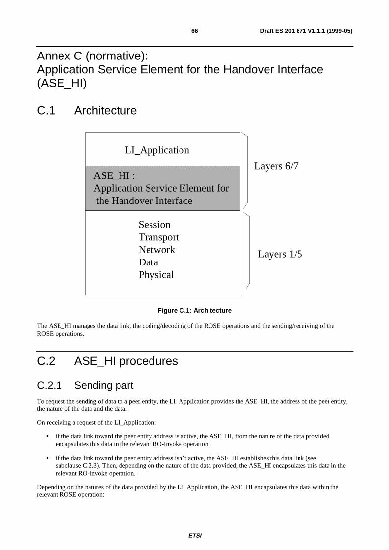
ETSI
Draft ES 201 671 V1.1.1 (1999-05)66
Annex C (normative):Application Service Element for the Handover Interface(ASE_HI)
C.1 Architecture
LI_Application
ASE_HI :Application Service Element for the Handover Interface
SessionTransportNetworkDataPhysical
Layers 6/7
Layers 1/5
Figure C.1: Architecture
The ASE_HI manages the data link, the coding/decoding of the ROSE operations and the sending/receiving of theROSE operations.
C.2 ASE_HI procedures
C.2.1 Sending partTo request the sending of data to a peer entity, the LI_Application provides the ASE_HI, the address of the peer entity,the nature of the data and the data.
On receiving a request of the LI_Application:
• if the data link toward the peer entity address is active, the ASE_HI, from the nature of the data provided,encapsulates this data in the relevant RO-Invoke operation;
• if the data link toward the peer entity address isn’t active, the ASE_HI establishes this data link (seesubclause C.2.3). Then, depending on the nature of the data provided, the ASE_HI encapsulates this data in therelevant RO-Invoke operation.
Depending on the natures of the data provided by the LI_Application, the ASE_HI encapsulates this data within therelevant ROSE operation:
ETSI
Draft ES 201 671 V1.1.1 (1999-05)67
• LI management notification: in this case the data provided by the application are encoded within the class 2RO-Invoke operation "Sending_of_HI1_Notification". The ASN1 format is described in Annex A, Table 1 andTable 3 (HI1 interface).
• IRI: in this case the data provided by the application are encoded within the class 2 RO-Invoke operationSending_of_IRI. The ASN1 format is described in Annex A, Table 1 and Table 4 (HI2 interface).
• SMS: in this case the data provided by the application are encoded within the class 2 RO-Invoke operationSending_of_IRI. The ASN1 format is described in Annex A, Table 1 and Table 4 (HI2 interface).
• User packet data transfer (used for data which can be exchanged via ISUP/DSS1/MAP signalling: e.g. UUS): inthis case the data provided by the application are encoded:
• either within the class 2 RO-Invoke operation "Circuit-Call-related-services" in case of data associated toa circuit call (for e.g. UUS 1 to 3) The ASN1 format is described in Annex A, Table 1 and Table 5 (HI3interface).
• either within the class 2 RO-Invoke operation "No-Circuit-Call-related-services" in case of data notassociated with a circuit call (for e.g. UUS 4.) The ASN1 format is described in Annex A, Table 1 andTable 5 (HI3 interface).
• TETRA data transfer: in this case all the information provided by the application are encoded within the class 2RO-Invoke operation "Sending_of_TETRA_Data". The ASN1 format is described in Annex A, Table 1 andTable 6.
• GPRS data transfer: in this case all the information provided by the application are encoded within the class 2RO-Invoke operation "Sending_of_GPRS_Data". The ASN1 format is described in Annex A, Table 1 andTable 7.
Depending on the class of the operation, the ASE_HI may have to wait for an answer. In this case a timer, depending onthe operation, is started on the sending of the operation and stopped on the receipt of an answer (RO_Result, RO_Error,RO_Reject).
On timeout of the timer, the ASE_HI indicates to the LI_Application that no answer has been received. It is under theLI_Application responsability to send again the data or to inform the administrator of the problem.
On receipt of an answer component (after verification that the component isn’t erroneous), the ASE_HI stop the relevanttimer and acts depending on the type of component:
• on receipt of a RO_Result, the ASE_HI provide the relevant LI_Application an indication that the data has beenreceived by the peer LI-application and the possible parameters contained in the RO_Result.
• on receipt of a RO_Error, the ASE_HI provide the relevant LI_Application an indication that the data hasn’tbeen received by the peer LI-application and the possible "Error cause". The error causes are defined for eachoperation in the relevant ASN1 script. It is under the LI_Application responsability to generate or not an alarmmessage toward an operator or administrator.
• on receipt of a RO_Reject_U/P, the ASE_HI provide the relevant LI_Application an indication that the datahasn’t been received by the peer LI-application and the "Problem cause". The "problem causes" are definedin [35] to [37]. It is under the LI_Application responsibility to send again the data or to inform theoperator/administrator of the error.
On receipt of an erroneous component, the ASE_HI acts as described in ITU-T Recommendations [35] to [37].
C.2.2 Receiving partOn receipt of a ROSE operation from the lower layers:
• When receiving operations from the peer entity, the ASE_HI verifies the syntax of the component and transmitsthe parameters to the LI-Application. If no error/problem is detected, in accordance with the [35] to [37] standardresult (only Class2 operation are defined), the ASE_HI sends back a RO_Result which coding is determined bythe relevant operation ASN1 script. The different operations which can be received are:
ETSI
Draft ES 201 671 V1.1.1 (1999-05)68
• RO-Invoke operation "Sending-of-HI1-Notification" (HI1 interface);
• RO-Invoke operation "Sending-of-IRI" (HI2 interface);
• RO-Invoke operation "Circuit-Call-Related-Services" (HI3 interface);
• RO-Invoke operation "No-Circuit-Call-Related-Services" (HI3 interface);
• RO-Invoke operation "Sending-of-TETRA-Data" (HI3 interface);
• RO-Invoke operation "Sending-of-GPRS-Data" (HI3 interface).
In case of error, the ASE_HI acts depending on the reason of the error or problem:
• in accordance with the rules defined by [35] to [37], an RO_Error is sent in case of unsuccessfully operation atthe application level. The Error cause provided is one among those defined by the ASN1 script of the relevantoperation.
• in accordance with the rules defined in [35] to [37], an RO_Reject_U/P is sent in case of erroneous component.On receipt of an erroneous component, the ASE_HI acts as described in [35] to [37].
C.2.3 Data link managementThis function is used to establish or release a data link between two peer LI_Applications entities (MF and LEMF).
Depending on a per destination address configuration data, the data link establishment may be required either by theLEMF LI_Application or by the MF LI_Application.
C.2.3.1 Data link establishment
To request the establishment of a data link toward a peer entity, the LI_Application provides, among others, thedestination address of the peer entity (implicitly, this address defined the protocol layers immediately under theASE_HI: TCP/IP, X25, …). On receipt of this request, the ASE_HI request the establishment of the data link withrespect of the rules of the under layers protocol.
As soon as the data link is established, the requesting LI_Application initiates an authentication procedure:
• the origin LI_Application requests the ASE_HI to send the class 2 RO-Invoke operation "Sending_of_Password"which includes the "origin password" provided by the LI_Application;
• the peer LI-Application, on receipt of the "origin password" and after acceptance, requests to its ASE_HI to sendback a RO-Result. In addition, this destination application requests the ASE_HI to send the class 2 RO-Invokeoperation "Sending_of_Password" which includes the "destination password" provided by the LI_Application;
• the origin LI-Application, on receipt of the "destination password" and after acceptance, requests to its ASE_HIto send back a RO-Result. This application is allowed to send data;
• after receipt of the RO_Result, this application is allowed to send data.
In case of erroneous password, the data link is immediately released and an "password error indication" is sent towardthe operator.
Optionally a Data link test procedure may be used to verify periodically the data link:
• When no data have been exchanged during a network dependent period of time toward an address, (may varyfrom 1 to 30 minutes) the LI_Application requests the ASE_HI to send the class 2 RO-Invoke operationData-Link-Test.
• The peer LI-Application, on receipt of this operation , requests to it’s ASE_HI to send back a RO-Result.
• On receipt of the Result the test is considered valid by the LI_Application.
ETSI
Draft ES 201 671 V1.1.1 (1999-05)69
• If no Result is received or if a Reject/Error message is received, the LI_Aplication requests the ASE_LI torelease the data link and send an error message toward the operator.
C.2.3.2 Data link release
• The End of the connection toward the peer LI_Application is under responsibility of the LI_Application. E.g, theEnd of the connection may be requested in the following cases:
• When all the data (IRI, …) has been sent. To prevent unnecessary release, the datalink may be releasedonly when no LI_Application data have been exchanged during a network dependent period of time.
• The data link is established when a call is intercepted and released when the intercepted call is released(and all the relevant data have been sent).
• For security purposes.
• For changing of password or address of the LEMF/IIF.
• Etc.
• To end the connection an LI_Application requests the ASE_HI to send the class 2 RO-Invoke operation"End_Of_Connection".
• The peer LI-Application, on receipt of this operation , requests to it’s ASE_HI to send back a RO_Result.
• On receipt of the Result the LI_Application requests the ASE_LI to release the data link.
• If no Result is received after a network dependent period of time, or if a Reject/Error message is received, theLI_Application requests the ASE_LI to release the data link and to send an error message toward theoperator/administrator.
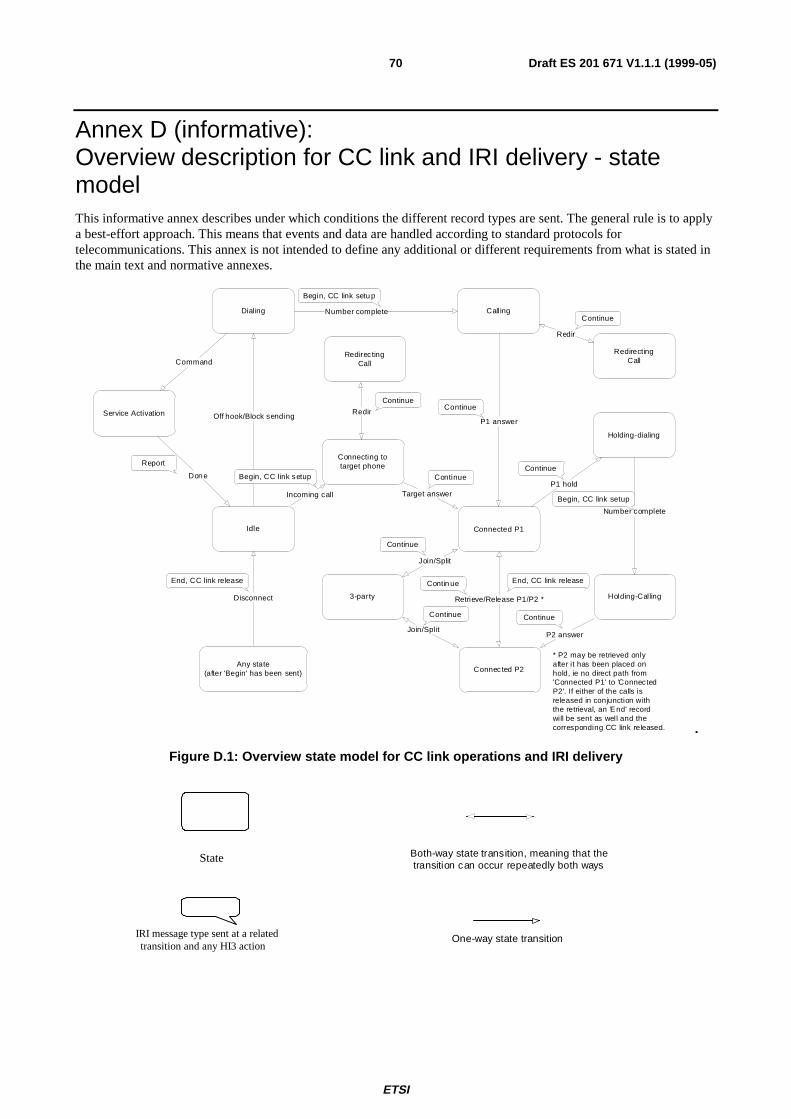
ETSI
Draft ES 201 671 V1.1.1 (1999-05)70
Annex D (informative):Overview description for CC link and IRI delivery - statemodelThis informative annex describes under which conditions the different record types are sent. The general rule is to applya best-effort approach. This means that events and data are handled according to standard protocols fortelecommunications. This annex is not intended to define any additional or different requirements from what is stated inthe main text and normative annexes.
Dialing Calling
Connected P1
Holding-dialing
Holding-Calling
Connected P2
3-party
Idle
Number complete
P1 answer
P1 hold
P2 answer
Retrieve/Release P1/P2 *
Join/Split
Join/Split
Number complete
Disconnect
Begin, CC link setu p
Continue
Report
End, CC link release
Continue
Begin, CC link setup
Continue
Continue
Contin ue
Continue
End, CC link release
Service Activation
Command
Don e
* P2 may be retrieved onlyafter it has been placed onhold, ie no direct path from'Connected P1' to 'ConnectedP2'. If either of the calls isreleased in conjunction withthe retrieval, an 'E nd' recordwill be sent as well and thecorresponding CC link released.
Redirec tingCall
Continue
Off hook/Block sending
Connecting totarget phone
Incoming call Target answer
Continue
RedirectingCall
Redir
Continue
Begin, CC link setup
Redir
Any state(after 'Begin' has been sent)
.
Figure D.1: Overview state model for CC link operations and IRI delivery
State Both-way state transition, meaning that the transition can occur repeatedly both ways
IRI message type sent at a related transition and any HI3 action
One-way state transition
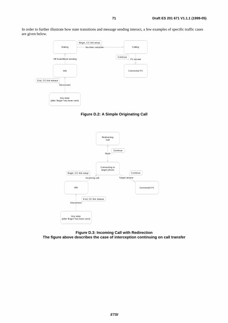
ETSI
Draft ES 201 671 V1.1.1 (1999-05)71
In order to further illustrate how state transitions and message sending interact, a few examples of specific traffic casesare given below.
Dialing Calling
Connected P1Idle
Nu mber complete
P1 answer
Any state(after 'Begin' has been sent)
Disconnect
Begin, CC link setup
Continue
End, CC link release
Off hook/Block sending
Figure D.2: A Simple Originating Call
Connected P1Idle
Any state(after 'B egin' has been sent)
Disconnect
E nd, CC link release
RedirectingCall
Continue
Connecting totarget phone
Incoming call Target answer
ContinueB egin, CC link setup
Redir
Figure D.3: Incoming Call with RedirectionThe figure above describes the case of interception continuing on call transfer
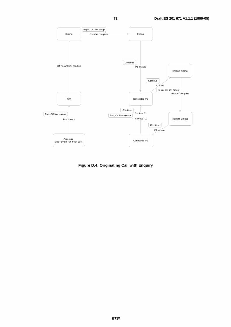
ETSI
Draft ES 201 671 V1.1.1 (1999-05)72
Dialing Calling
Connected P1
Holding-dialing
Holding-Calling
Connected P2
Idle
Number complete
P1 answer
P1 hold
P2 answer
Number complete
Any state(after 'Begin' has been sent)
Disconnect
Begin, CC link setup
Continue
End, CC link release
Continue
Begin, CC link setup
Con tinue
Continue
Off hook/Block send ing
End, CC link releaseRetrieve P1
Release P2
Figure D.4: Originating Call with Enquiry
ETSI
Draft ES 201 671 V1.1.1 (1999-05)73
Annex E (informative):Message Sequence Diagrams, IRI content
E.1 General remarksThe tables and message sequence diagrams (scenarios) of this section are typical examples, showing which parametersshall be included in the IRI records, and when the records shall be sent out to the LEA, for different call phases, callconfigurations and the invocation of supplementary services. The purpose of this annex is, to supplement and clarify theprocedures and the use of parameters, which are specified in the main body and the normative annexes of the presentdocument. These normative parts have precedence, in case of ambiguities.
A general principle for handling complex call configurations is, to break down the scenarios for LI related tasks intoseveral sub-scenarios, which are ideally identical for parts of basic calls or other "standard" call situations. This reducessignificantly the complexity of specifying and realizing the LI related tasks. As a consequence, the scenarios belowcontain in many cases just a remark to another scenario, with the applicable sequence, see example below.
EXAMPLE: Call Forwarding on No Reply (CFNR) is active for a target (party B).
1) An incoming call is, after a time-out, released at the target’s access, but forwarded by the exchange. Thesequence up to the release is handled like a call released by B during ringing.
2) The following set up of the forwarded call to a party C is handled in the same way as for immediateforwarding, e.g. CFU.
Both transactions can be treated independently of each other, a specific, new sequence for CFNR is not needed.
The tables and scenarios of this annex contain several typical cases, they are not covering all possible combinations.They are structured into clauses as follows:
Basic calls
E.4 Originating target, basic call
E.5 Terminating target, basic call
Call with supplementary services being invoked
E.6 Originating target call, invocation of LI relevant services
E.7 Terminating target call, invocation of LI relevant services
E.8 Target actions during a call in progress
E.9 Three Party Service (3PTY)
E.10 Add on conference (CONF
E.11 Target exchange receives notification related to other party
Subscriber controlled input (SCI)
E.12 Service Activation (not call related)
E.13 Service activation / invocation during a call
ETSI
Draft ES 201 671 V1.1.1 (1999-05)74
Unsuccessful calls
E.14 Unsuccessful calls from target (originating), IRI-BEGIN record sent
E.15 Unsuccessful calls from / to target, IRI-BEGIN record not sent
E.2 Remarks to tablesWithin the tables, the parameters of an IRI record, which are significant for the specific case are indicated. They depend,except for the mandatory parameters, of the type of a target call. The order of the IRI parameters is not fixed. Thecomplete set of parameters, which may be part of an IRI record, follows from the general rules of subclauses 8.5 and10.3. The parameter notation uses the ASN.1 definitions of Annex A.
Unless otherwise stated, the tables are applicable to all kinds of originating or terminating accesses, like ISDN andanalogue subscribers. Restrictions or differences may be mentioned in the row "remarks" or within additional text.
Mapping of parameters originated from other signalling systems than DSS1 or ISUP shall follow existing interworkingspecifications.
Only parameters and signals, which are available from the standard signalling procedures shall be included; noadditional procedures need to be used for LI to obtain parameters, which are not available by default. For example, norequest for a missing CLI need to be made, even if the signalling system would allow it.
Regarding the accuracy of the time stamp value of a record, it may be determined at any point in time during the periodbetween the detection of an event and the sending of the related record.
E.3 Remarks to scenariosThe included scenarios are examples. They show successful LI invocations within a local exchange; exceptional casesare not included. In case of ambiguities, the text of the main body and the normative annexes shall have priority.
The indicated call handling messages do in general not base on a specific protocol; however, in several cases, protocolspecific information needs to be mentioned; in these cases, the DSS1 functional access protocol is used, because it is akind of superset standard of protocol features. Within the figures, such cases are indicated by using DSS1 protocolmessage names in capital letters. Message sequences for other protocols, like for analogue accesses, should be derivedfrom the specified sequences.
The scenarios do not show all signalling protocol messages. Emphasis is on those messages, which are significant for orrelated to IRI records and CC link events.
The IRI record parameters, which are indicated as an additional information in the scenarios, are limited to significantones for a given case; e.g. parameters, which are mandatory, like the LIID, data & time, etc., are not explicitlymentioned. The parameter names use logical names, as defined in the tables of clause 8, instead of the exact ASN.1notation.
It is not required, that, depending on the actual access or network protocols, and the call configuration, e.g. purely localcalls, or calls via other exchanges, for the same actions of a target or another party, exactly the same sequences areresulting.
The master configuration, for decisions, which parameters ought to be included in IRI records, are transit calls usingISDN user part signalling. This means for example, that the information, which can be provided by such calls, shall alsobe available in case of purely local calls. As described above, the individual IRI records, which carry a certaininformation, may vary.
As a general rule, intercept related information is transmitted to the LEMF within an IRI record, when it gets firstavailable. Identical parameters are in the scenarios not repeated in succeeding records, unless their content or value haschanged; however, an implementation may decide to repeat information, which has already been sent, e.g. in order toavoid the need for a memory of already sent parameters.
ETSI
Draft ES 201 671 V1.1.1 (1999-05)75
With respect to the CC links in case of multi party calls, the options "CC links for active and non-active calls" is shown(option A).
In general, the scenario figures contain one or more pictures, depicting the actual configuration of the target and theother party(ies) within a call, and the target’s call state.
Functional entities used within the scenarios:
• Target terminal: Equipment of the interception subject, which originates or terminates an intercepted call.
• Orig. / term. SF_T: Switching function of the target, containig the IIF; within these examples, the SF_T is assumed to be a fixed ISDN network local exchange.
• Orig. / term. SF_P: Switching function of the other party; within these examples, the SF_P is assumed to be a fixed ISDN network local exchange.
• Other party: Equipment of the other party(ies), which originates or terminates a call, in which the target is involved.
• LEMF HI2 (IRI): LEMF port, receiving IRI.
• LEMF HI3 (CC): LEMF port, receiving the content of communication (CC links).
NOTE: An incoming message to any functional entity causes in general one or more outgoing messages; in case ofseveral outgoing messages, the order of sending them is purely implementation dependent, the figures donot intend to specify a fixed sequence.
E.4 Originating target, basic callThis section concentrates on the description of basic calls, originated by the target; however, the IRI record tables depictpartly also parameters, which can be used in conjunction with the invocation of supplementary services.
E.4.1 Initial LI proceduresThis subclause includes the procedure until the point in time, when the local exchange of the target (SF_T) sends an IRI-BEGIN record, and sets up a CC link.
Corresponding transition in state model: Begin, CC link set up (the state model shows the special case of en-blocdialing).
The IRI-BEGIN record constitutes the first record of an originating or terminating call.
NOTE: The exact point of sending the IRI-BEGIN record may depend on national regulations, and on theimplementation of the IIF. It may e.g. be sent immediately when connecting dial tone, or only, whenstarting routing within the SF_T. Irrespective of the point in time of sending the IRI-BEGIN record, itshall be possible to send an IRI-REPORT record, if a call is released at an earlier point in time.
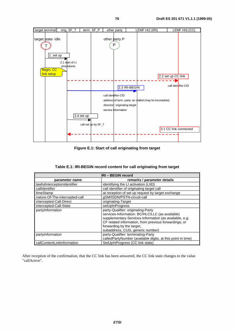
ETSI
Draft ES 201 671 V1.1.1 (1999-05)76
target terminal orig. SF_T term. SF_P other party LEMF HI2 (IRI) LEMF HI3 (CC)
target state: idle other party P
2.1 start of LI procedures
call identifier CID
call identifier CID
address of term. party: as dialled (may be incomplete)
direction: originating target
service information
call set up by SF_T
1. set up
2.3 IRI-BEGIN
2.2 set up CC link
2.4 set up
3.1 CC link connected
T P
Begin, CC link setup
Figure E.1: Start of call originating from target
Table E.1: IRI-BEGIN record content for call originating from target
IRI – BEGIN recordparameter name remarks / parameter details
lawfulInterceptionIdentifier identifying the LI activation (LIID)callIdentifier call identifier of originating target calltimeStamp at reception of set up request by target exchangenature-Of-The-intercepted-call gSM/ISDN/PSTN-circuit-callintercepted-Call-Direct originating-Targetintercepted-Call-State setUpInProgresspartyInformation party-Qualifier: originating-Party
services-Information: BC/HLC/LLC (as available)supplementary-Services-Information (as available, e.g.CF related information, from previous forwardings, orforwarding by the target,subaddress, CUG, generic number)
partyInformation party-Qualifier: terminating-PartycalledPartyNumber (available digits, at this point in time)
callContentLinkInformation SetUpInProgress (CC link state)
After reception of the confirmation, that the CC link has been answered, the CC link state changes to the value"callActive".
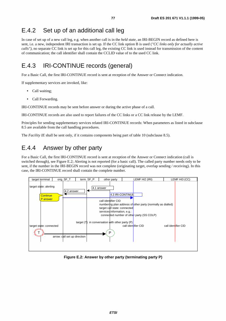
ETSI
Draft ES 201 671 V1.1.1 (1999-05)77
E.4.2 Set up of an additional call legIn case of set up of a new call leg, e.g. when another call is in the held state, an IRI-BEGIN record as defined here issent, i.e. a new, independent IRI transaction is set up. If the CC link option B is used ("CC links only for actually activecalls"), no separate CC link is set up for this call leg, the existing CC link is used instead for transmission of the contentof communication; the call identifier shall contain the CCLID value of to the used CC link.
E.4.3 IRI-CONTINUE records (general)For a Basic Call, the first IRI-CONTINUE record is sent at reception of the Answer or Connect indication.
If supplementary services are invoked, like:
• Call waiting;
• Call Forwarding.
IRI-CONTINUE records may be sent before answer or during the active phase of a call.
IRI-CONTINUE records are also used to report failures of the CC links or a CC link release by the LEMF.
Principles for sending supplementary services related IRI-CONTINUE records: When parameters as listed in subclause8.5 are available from the call handling procedures.
The Facility IE shall be sent only, if it contains components being part of table 10 (subclause 8.5).
E.4.4 Answer by other partyFor a Basic Call, the first IRI-CONTINUE record is sent at reception of the Answer or Connect indication (call isswitched through), see Figure E.2; Alerting is not reported (for a basic call). The called party number needs only to besent, if the number in the IRI-BEGIN record was not complete (originating target, overlap sending / receiving). In thiscase, the IRI-CONTINUE record shall contain the complete number.
target terminal orig. SF_T term. SF_P other party LEMF HI2 (IRI) LEMF HI3 (CC)
target state: alerting
call identifier CIDnumbering plan address of other party (normally as dialled)target call state: connected services information, e.g.: connected number of other party (SS COLP)
target (T) in conversation with other party (P)target state: connected call identifier CID call identifier CID
arrow: call set up direction
4.1 answer4.2 answer
4.3 IRI-CONTINUE
P
ContinueP answer
T
Figure E.2: Answer by other party (terminating party P)
ETSI
Draft ES 201 671 V1.1.1 (1999-05)78
Table E.2 : IRI-CONTINUE record content during call establishment, answer indication received
IRI – CONTINUE recordparameter name remarks / parameter details
callIdentifier call identifier of originating target calltimeStamp at reception of answer indication by target exchangenature-Of-The-intercepted-call gSM/ISDN/PSTN-circuit-callintercepted-Call-State connectedSimpleIndication only for targets, e.g.:
call-Waiting-Indication (call is waiting at terminating target)partyInformation party-Qualifier: originating-Party
services-Information: BC/HLC/LLC (if different from value inIRI-BEGIN record)supplementary-Services-Information (new information, asavailable)
partyInformation party-Qualifier: terminating-PartycalledPartyNumber (only if "other party": full number of otherparty)supplementary-Services-Information (new information, asavailable, e.g.: connected number (Note 2), connectedsubaddress, generic notification indicator)
lawfulInterceptionIdentifier identifying the LI activation (LIID)callContentLinkInformation callActive (normal case)NOTE 1: This table relates to both cases, a target being originating or terminating party.NOTE 2: In case of a terminating target, the connected number is only included, if it is not equal to
the target identity.
E.4.5 Call release (originating or terminating target)In case of an unsuccessful call, an IRI-END Record is sent, if before an IRI-BEGIN record has been sent. If a target callis released before sending an IRI-BEGIN record, an IRI-REPORT record is sent instead, see clause E.15.
NOTE 1: The figure below does not show the detailed DSS1 or ISUP release sequences.
NOTE 2: The exact point of sending the IRI-END record may depend on national regulations, and on theimplementation of the IIF. It may, e.g. in case of DSS1, be sent immediately when receiving / sending theRELEASE message, or when sending / receiving RELEASE COMPLETE.
The IRI-END Record is also applicable, if the released call was a call e.g. forwarded or transferred by the target.
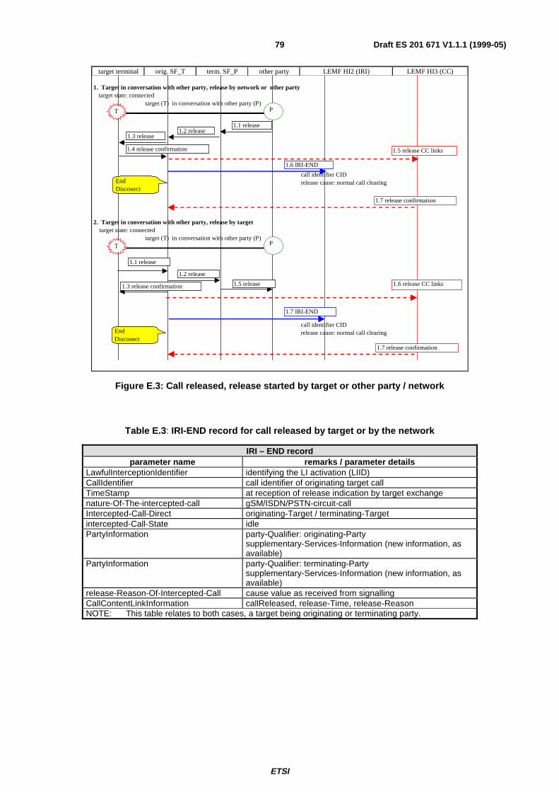
ETSI
Draft ES 201 671 V1.1.1 (1999-05)79
target terminal orig. SF_T term. SF_P other party LEMF HI2 (IRI) LEMF HI3 (CC)
1. Target in conversation with other party, release by network or other party target state: connected
target (T) in conversation with other party (P)
call identifier CIDrelease cause: normal call clearing
2. Target in conversation with other party, release by target target state: connected
target (T) in conversation with other party (P)
call identifier CIDrelease cause: normal call clearing
1.1 release1.2 release
1.6 IRI-END
1.5 release CC links
1.3 release
T P
1.5 release
1.2 release
1.7 IRI-END
1.6 release CC links
1.1 release
T P
1.7 release confirmation
EndDisconect
EndDisconect
1.7 release confirmation
1.4 release confirmation
1.3 release confirmation
Figure E.3: Call released, release started by target or other party / network
Table E.3 : IRI-END record for call released by target or by the network
IRI – END recordparameter name remarks / parameter details
LawfulInterceptionIdentifier identifying the LI activation (LIID)CallIdentifier call identifier of originating target callTimeStamp at reception of release indication by target exchangenature-Of-The-intercepted-call gSM/ISDN/PSTN-circuit-callIntercepted-Call-Direct originating-Target / terminating-Targetintercepted-Call-State idlePartyInformation party-Qualifier: originating-Party
supplementary-Services-Information (new information, asavailable)
PartyInformation party-Qualifier: terminating-Partysupplementary-Services-Information (new information, asavailable)
release-Reason-Of-Intercepted-Call cause value as received from signallingCallContentLinkInformation callReleased, release-Time, release-ReasonNOTE: This table relates to both cases, a target being originating or terminating party.
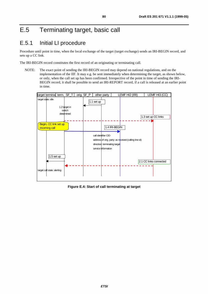
ETSI
Draft ES 201 671 V1.1.1 (1999-05)80
E.5 Terminating target, basic call
E.5.1 Initial LI procedureProcedure until point in time, when the local exchange of the target (target exchange) sends an IRI-BEGIN record, andsets up a CC link.
The IRI-BEGIN record constitutes the first record of an originating or terminating call.
NOTE: The exact point of sending the IRI-BEGIN record may depend on national regulations, and on theimplementation of the IIF. It may e.g. be sent immediately when determining the target, as shown below,or only, when the call set up has been confirmed. Irrespective of the point in time of sending the IRI-BEGIN record, it shall be possible to send an IRI-REPORT record, if a call is released at an earlier pointin time.
target terminal term. SF_T orig. SF_P other party LEMF HI2 (IRI) LEMF HI3 (CC)target state: idle
1.2 target in switch
determined
call identifier CID
address of orig. party: as received (calling line id)
direction: terminating target
service information
target call state: alerting
1.1 set up
1.4 IRI-BEGIN
1.5 set up
1.3 set up CC links
2.1 CC links connected
Begin, CC link set up incoming call
Figure E.4: Start of call terminating at target
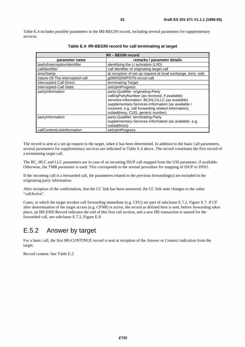
ETSI
Draft ES 201 671 V1.1.1 (1999-05)81
Table E.4 includes possible parameters in the IRI-BEGIN record, including several parameters for supplementaryservices.
Table E.4 : IRI-BEGIN record for call terminating at target
IRI – BEGIN recordparameter name remarks / parameter details
lawfulInterceptionIdentifier identifying the LI activation (LIID)callIdentifier call identifier of originating target calltimeStamp at reception of set up request at local exchange, term. sidenature-Of-The-intercepted-call gSM/ISDN/PSTN-circuit-callintercepted-Call-Direct terminating-Targetintercepted-Call-State setUpInProgresspartyInformation party-Qualifier: originating-Party
callingPartyNumber (as received, if available)services-Information: BC/HLC/LLC (as available)supplementary-Services-Information (as available /received, e.g. call forwarding related information),subaddress, CUG, generic number)
partyInformation party-Qualifier: terminating-Partysupplementary-Services-Information (as available, e.g.subaddress)
callContentLinkInformation setUpInProgress
The record is sent at a set up request to the target, when it has been determined. In addition to the basic call parameters,several parameters for supplementary services are indicated in Table E.4 above. The record constitutes the first record ofa terminating target call.
The BC, HLC and LLC parameters are in case of an incoming ISUP call mapped from the USI parameter, if available.Otherwise, the TMR parameter is used. This corresponds to the normal procedure for mapping of ISUP to DSS1.
If the incoming call is a forwarded call, the parameters related to the previous forwarding(s) are included in theoriginating party information.
After reception of the confirmation, that the CC link has been answered, the CC link state changes to the value"callActive".
Cases, in which the target invokes call forwarding immediate (e.g. CFU) are part of subclause E.7.2, Figure E.7. If CFafter determination of the target access (e.g. CFNR) is active, the record as defined here is sent; before forwarding takesplace, an IRI-END Record indicates the end of this first call section, and a new IRI transaction is started for theforwarded call, see subclause E.7.2, Figure E.8.
E.5.2 Answer by targetFor a basic call, the first IRI-CONTINUE record is sent at reception of the Answer or Connect indication from thetarget.
Record content: See Table E.2.
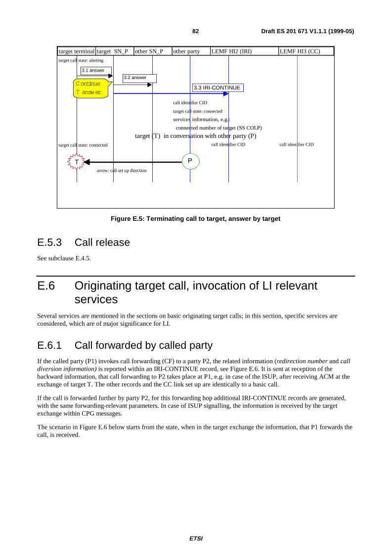
ETSI
Draft ES 201 671 V1.1.1 (1999-05)82
target terminal target SN_P other SN_P other party LEMF HI2 (IRI) LEMF HI3 (CC)
target call state: alerting
call identifier CID
target call state: connected
services information, e.g.:
connected number of target (SS COLP)
target (T) in conversation with other party (P)target call state: connected call identifier CID call identifier CID
arrow: call set up direction
3.1 answer
3.2 answer
3.3 IR I-CONT INUE
T P
ContinueT answer
Figure E.5: Terminating call to target, answer by target
E.5.3 Call releaseSee subclause E.4.5.
E.6 Originating target call, invocation of LI relevantservices
Several services are mentioned in the sections on basic originating target calls; in this section, specific services areconsidered, which are of major significance for LI.
E.6.1 Call forwarded by called partyIf the called party (P1) invokes call forwarding (CF) to a party P2, the related information (redirection number and calldiversion information) is reported within an IRI-CONTINUE record, see Figure E.6. It is sent at reception of thebackward information, that call forwarding to P2 takes place at P1, e.g. in case of the ISUP, after receiving ACM at theexchange of target T. The other records and the CC link set up are identically to a basic call.
If the call is forwarded further by party P2, for this forwarding hop additional IRI-CONTINUE records are generated,with the same forwarding-relevant parameters. In case of ISUP signalling, the information is received by the targetexchange within CPG messages.
The scenario in Figure E.6 below starts from the state, when in the target exchange the information, that P1 forwards thecall, is received.
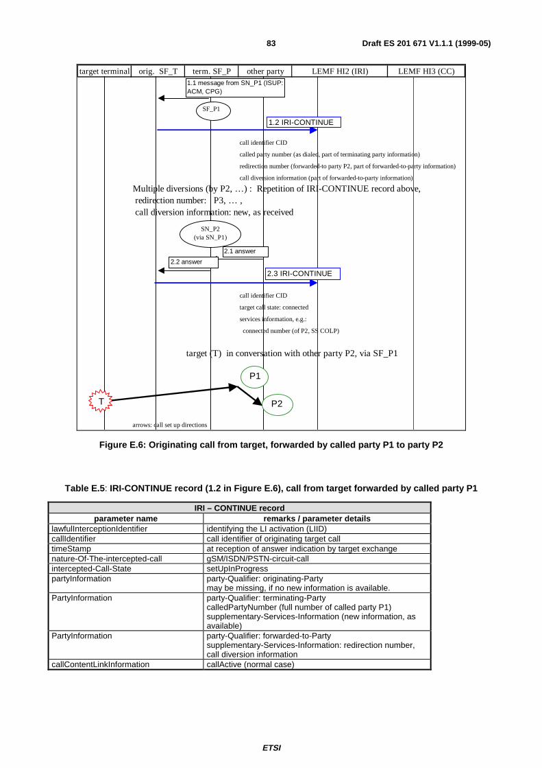
ETSI
Draft ES 201 671 V1.1.1 (1999-05)83
target terminal orig. SF_T term. SF_P other party LEMF HI2 (IRI) LEMF HI3 (CC)
call identifier CID
called party number (as dialed, part of terminating party information)
redirection number (forwarded-to party P2, part of forwarded-to-party information)
call diversion information (part of forwarded-to-party information)
Multiple diversions (by P2, …) : Repetition of IRI-CONTINUE record above, redirection number: P3, … , call diversion information: new, as received
call identifier CID
target call state: connected
services information, e.g.:
connected number (of P2, SS COLP)
target (T) in conversation with other party P2, via SF_P1
arrows: call set up directions
T
P1
P2
1.1 mes sage from S N_P1 (IS UP: ACM, CPG)
1.2 IR I-CONT INUE
2.1 answer
2.2 answer
2.3 IR I-CONT INUE
SF_P1
SN_P2(via SN_P1)
Figure E.6: Originating call from target, forwarded by called party P1 to party P2
Table E.5 : IRI-CONTINUE record (1.2 in Figure E.6), call from target forwarded by called party P1
IRI – CONTINUE recordparameter name remarks / parameter details
lawfulInterceptionIdentifier identifying the LI activation (LIID)callIdentifier call identifier of originating target calltimeStamp at reception of answer indication by target exchangenature-Of-The-intercepted-call gSM/ISDN/PSTN-circuit-callintercepted-Call-State setUpInProgresspartyInformation party-Qualifier: originating-Party
may be missing, if no new information is available.PartyInformation party-Qualifier: terminating-Party
calledPartyNumber (full number of called party P1)supplementary-Services-Information (new information, asavailable)
PartyInformation party-Qualifier: forwarded-to-Partysupplementary-Services-Information: redirection number,call diversion information
callContentLinkInformation callActive (normal case)
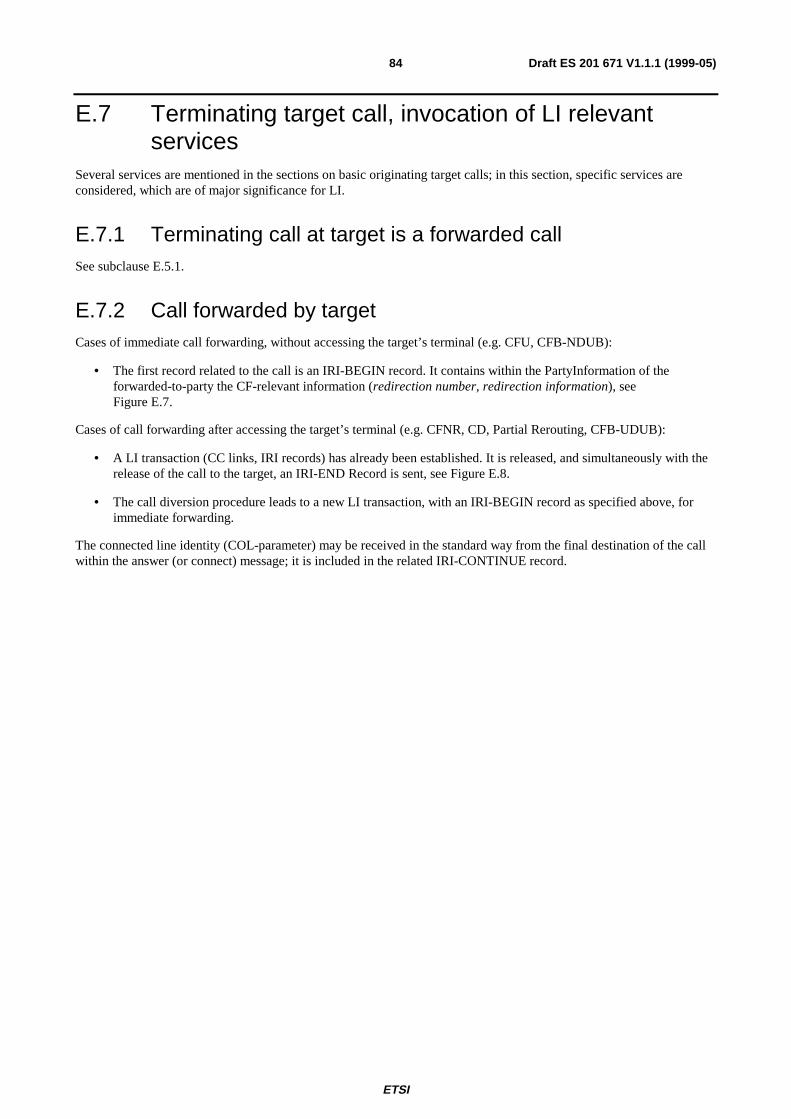
ETSI
Draft ES 201 671 V1.1.1 (1999-05)84
E.7 Terminating target call, invocation of LI relevantservices
Several services are mentioned in the sections on basic originating target calls; in this section, specific services areconsidered, which are of major significance for LI.
E.7.1 Terminating call at target is a forwarded callSee subclause E.5.1.
E.7.2 Call forwarded by targetCases of immediate call forwarding, without accessing the target’s terminal (e.g. CFU, CFB-NDUB):
• The first record related to the call is an IRI-BEGIN record. It contains within the PartyInformation of theforwarded-to-party the CF-relevant information (redirection number, redirection information), seeFigure E.7.
Cases of call forwarding after accessing the target’s terminal (e.g. CFNR, CD, Partial Rerouting, CFB-UDUB):
• A LI transaction (CC links, IRI records) has already been established. It is released, and simultaneously with therelease of the call to the target, an IRI-END Record is sent, see Figure E.8.
• The call diversion procedure leads to a new LI transaction, with an IRI-BEGIN record as specified above, forimmediate forwarding.
The connected line identity (COL-parameter) may be received in the standard way from the final destination of the callwithin the answer (or connect) message; it is included in the related IRI-CONTINUE record.
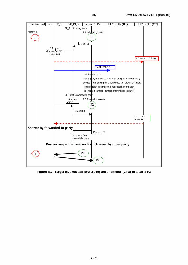
ETSI
Draft ES 201 671 V1.1.1 (1999-05)85
target terminal term. SF_T SF_P1, 2 parties P1, P2 LEMF HI2 (IRI) LEMF HI3 (CC)S F_P1 of calling party
target T P1: originating party
1.2 target determined, CFU
is invoked
call identifier CID
calling party number (part of originating party information)
service information (part of forwarded-to-Party information)
call divers ion information or redirection information
redirection number (number of forwarded-to party)
S F_P2 of forwarded-to party
P2: forwarded to party
Answer by forwarded-to party P2 / S F_P2
Further sequence: see section: Answer by other party
1.1 set up
1.5 set up (CFU)
T P1
1.6 set up
1.4 IRI-BEGIN
2.1 CC linksconnected
1.3 set up CC links
3.1 answer from forwarded-to party
P2
T P1
P2
Figure E.7: Target invokes call forwarding unconditional (CFU) to a party P2
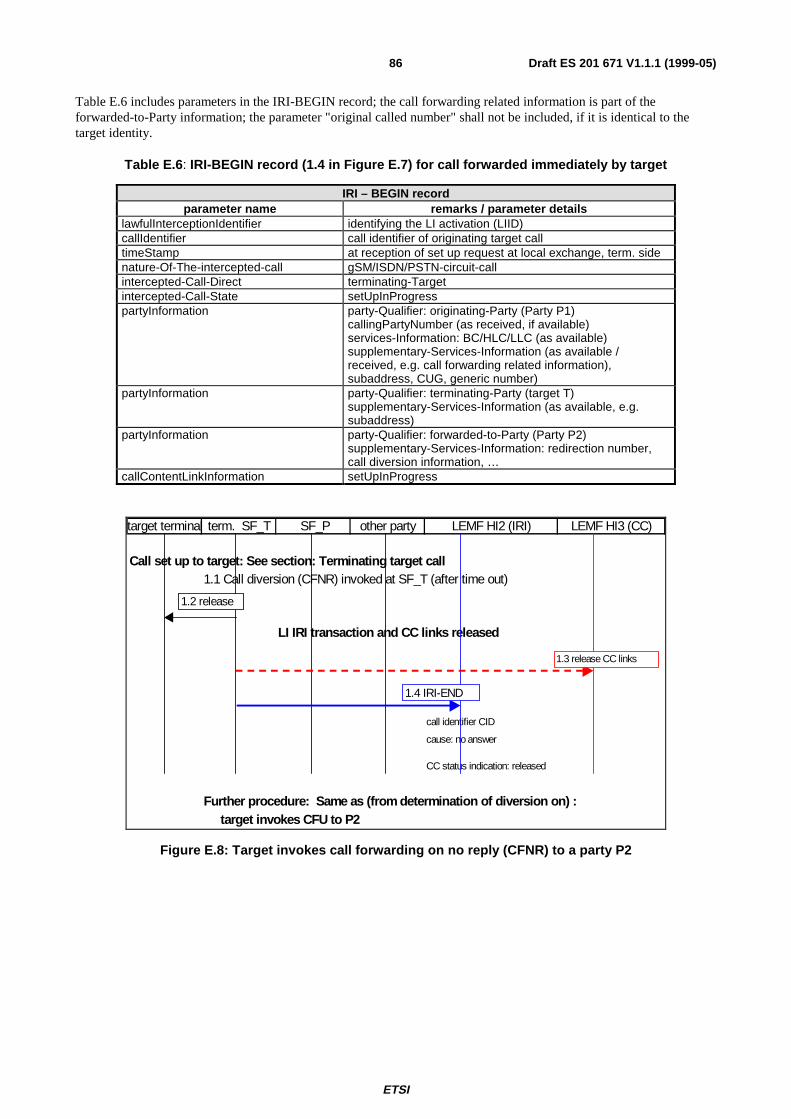
ETSI
Draft ES 201 671 V1.1.1 (1999-05)86
Table E.6 includes parameters in the IRI-BEGIN record; the call forwarding related information is part of theforwarded-to-Party information; the parameter "original called number" shall not be included, if it is identical to thetarget identity.
Table E.6 : IRI-BEGIN record (1.4 in Figure E.7) for call forwarded immediately by target
IRI – BEGIN recordparameter name remarks / parameter details
lawfulInterceptionIdentifier identifying the LI activation (LIID)callIdentifier call identifier of originating target calltimeStamp at reception of set up request at local exchange, term. sidenature-Of-The-intercepted-call gSM/ISDN/PSTN-circuit-callintercepted-Call-Direct terminating-Targetintercepted-Call-State setUpInProgresspartyInformation party-Qualifier: originating-Party (Party P1)
callingPartyNumber (as received, if available)services-Information: BC/HLC/LLC (as available)supplementary-Services-Information (as available /received, e.g. call forwarding related information),subaddress, CUG, generic number)
partyInformation party-Qualifier: terminating-Party (target T)supplementary-Services-Information (as available, e.g.subaddress)
partyInformation party-Qualifier: forwarded-to-Party (Party P2)supplementary-Services-Information: redirection number,call diversion information, …
callContentLinkInformation setUpInProgress
target terminal term. SF_T SF_P other party LEMF HI2 (IRI) LEMF HI3 (CC)
Call set up to target: See section: Terminating target call 1.1 Call diversion (CFNR) invoked at SF_T (after time out)
LI IRI transaction and CC links released
call identifier CID
cause: no answer
CC status indication: released
Further procedure: Same as (from determination of diversion on) : target invokes CFU to P2
1.2 release
1.4 IRI-END
1.3 release CC links
Figure E.8: Target invokes call forwarding on no reply (CFNR) to a party P2
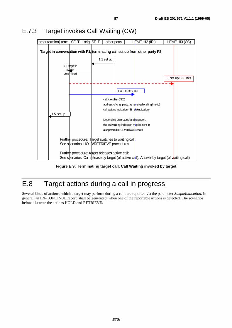
ETSI
Draft ES 201 671 V1.1.1 (1999-05)87
E.7.3 Target invokes Call Waiting (CW)
target terminal term. SF_T orig. SF_P other party LEMF HI2 (IRI) LEMF HI3 (CC)
Target in conversation with P1, terminatin g call set up from other part y P2
1.2 target in switch
determined
call identifier CID2
address of orig. party: as received (calling line id)
call waiting indication (SimpleIndication)
Depending on protocol and situation,
the call waiting indication may be sent in
a separate IRI-CONTINUE record
Further procedure: Target switches to waiting call: See scenarios: HOLD/RETRIEVE procedures
Further procedure: target releases active call: See scenarios: Call release by target (of active call), Answer by target (of waiting call)
1.1 set up
1.4 IRI-BEGIN
1.5 set up
1.3 set up CC links
Figure E.9: Terminating target call, Call Waiting invoked by target
E.8 Target actions during a call in progressSeveral kinds of actions, which a target may perform during a call, are reported via the parameter SimpleIndication. Ingeneral, an IRI-CONTINUE record shall be generated, when one of the reportable actions is detected. The scenariosbelow illustrate the actions HOLD and RETRIEVE.
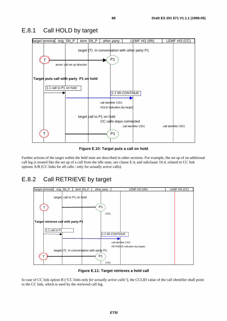
ETSI
Draft ES 201 671 V1.1.1 (1999-05)88
E.8.1 Call HOLD by target
target terminal orig. SN_P term SN_P other party LEMF HI2 (IRI) LEMF HI3 (CC)
target (T) in conversation with other party P1
arrow: call set up direction
Target puts call with party P1 on hold
call identifier CID1
HOLD indication (by target)
target call to P1 on holdCC calls stays connected
call identifier CID1 call identifier CID1
1.1 call to P1 on hold
1.2 IRI-CONTINUE
T P1
T P1
Figure E.10: Target puts a call on hold
Further actions of the target within the held state are described in other sections. For example, the set up of an additionalcall leg is treated like the set up of a call from the idle state, see clause E.4, and subclause 10.4, related to CC linkoptions A/B (CC links for all calls / only for actually active calls).
E.8.2 Call RETRIEVE by target
target terminal orig. SN_P term SN_P other party LEMF HI2 (IRI) LEMF HI3 (CC)
target: call to P1 on hold
CID1
Target retrieves call with party P1
call identifier CID1
RETRIEVE indication (by target)
target (T) in conversation with party P1
CID1
1.1 call to P1 1.2 IRI-CONTINUE
T P1
T P1
Figure E.11: Target retrieves a held call
In case of CC link option B ("CC links only for actually active calls"), the CCLID value of the call identifier shall pointto the CC link, which is used by the retrieved call leg.
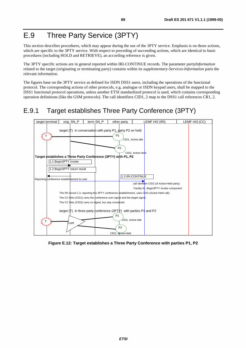
ETSI
Draft ES 201 671 V1.1.1 (1999-05)89
E.9 Three Party Service (3PTY)This section describes procedures, which may appear during the use of the 3PTY service. Emphasis is on those actions,which are specific to the 3PTY service. With respect to preceding of succeeding actions, which are identical to basicprocedures (including HOLD and RETRIEVE), an according reference is given.
The 3PTY specific actions are in general reported within IRI-CONTINUE records. The parameter partyInformationrelated to the target (originating or terminating party) contains within its supplementary-Services-Information parts therelevant information.
The figures base on the 3PTY service as defined for ISDN DSS1 users, including the operations of the functionalprotocol. The corresponding actions of other protocols, e.g. analogue or ISDN keypad users, shall be mapped to theDSS1 functional protocol operations, unless another ETSI standardized protocol is used, which contains correspondingoperation definitions (like the GSM protocols). The call identifiers CID1, 2 map to the DSS1 call references CR1, 2.
E.9.1 Target establishes Three Party Conference (3PTY)
target terminal orig. SN_P term SN_P other party LEMF HI2 (IRI) LEMF HI3 (CC)
target (T) in conversation with party P1, party P2 on hold
CID1, Active-Idle
CID2, Active-Held
Target establishes a Three Party Conference (3PTY) with P1, P2
Reporting conference establishement to user
call identifier CID2 (of Active-Held party)
Facility IE, Begin3PTY invoke component
The IRI record 1.3, reporting the 3PTY conference establishment, uses CID2 (Active-Held call).
The CC links (CID1) carry the conference sum signal and the target signal.
The CC links (CID2) carry no signal, but stay connected.
target (T) in three party conference (3PTY) with parties P1 and P2
CID1, Active-Idle
CID2, Active-Held
T
P2
P1
1.1 Begin3PTY invoke
1.2 Begin3PTY return result
1.3 IRI-CONTINUE
T
P2
P1
Conf.
Figure E.12: Target establishes a Three Party Conference with parties P1, P2
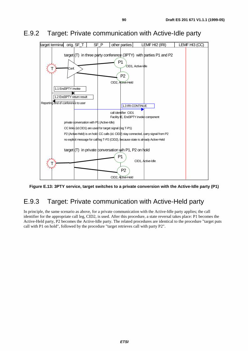
ETSI
Draft ES 201 671 V1.1.1 (1999-05)90
E.9.2 Target: Private communication with Active-Idle party
target terminal orig. SF_T SF_P other parties LEMF HI2 (IRI) LEMF HI3 (CC)
target (T) in three party conference (3PTY) with parties P1 and P2
CID1, Active-Idle
CID2, Active-Held
Reporting end of conference to user
call identifier CID1Facility IE, End3PTY invoke component
private conversation with P1 (Active-Idle)
CC links (id.CID1) are used for target signal (leg T-P1)
P2 (Active-Held) is on hold, CC calls (id. CID2) stay connected, carry signal from P2
no explicit message for call leg T-P2 (CID2), because state is already Active-Held
target (T) in private conversation wih P1, P2 on hold
CID1, Active-Idle
CID2, Active-Held
T
P2
P1Conf.
1.1 End3PTY invoke
1.2 End3PTY return result
1.3 IRI-CONTINUE
T
P2
P1
Figure E.13: 3PTY service, target switches to a private conversion with the Active-Idle party (P1)
E.9.3 Target: Private communication with Active-Held partyIn principle, the same scenario as above, for a private communication with the Active-Idle party applies; the callidentifier for the appropriate call leg, CID2, is used. After this procedure, a state reversal takes place: P1 becomes theActive-Held party, P2 becomes the Active-Idle party. The related procedures are identical to the procedure "target putscall with P1 on hold", followed by the procedure "target retrieves call with party P2".
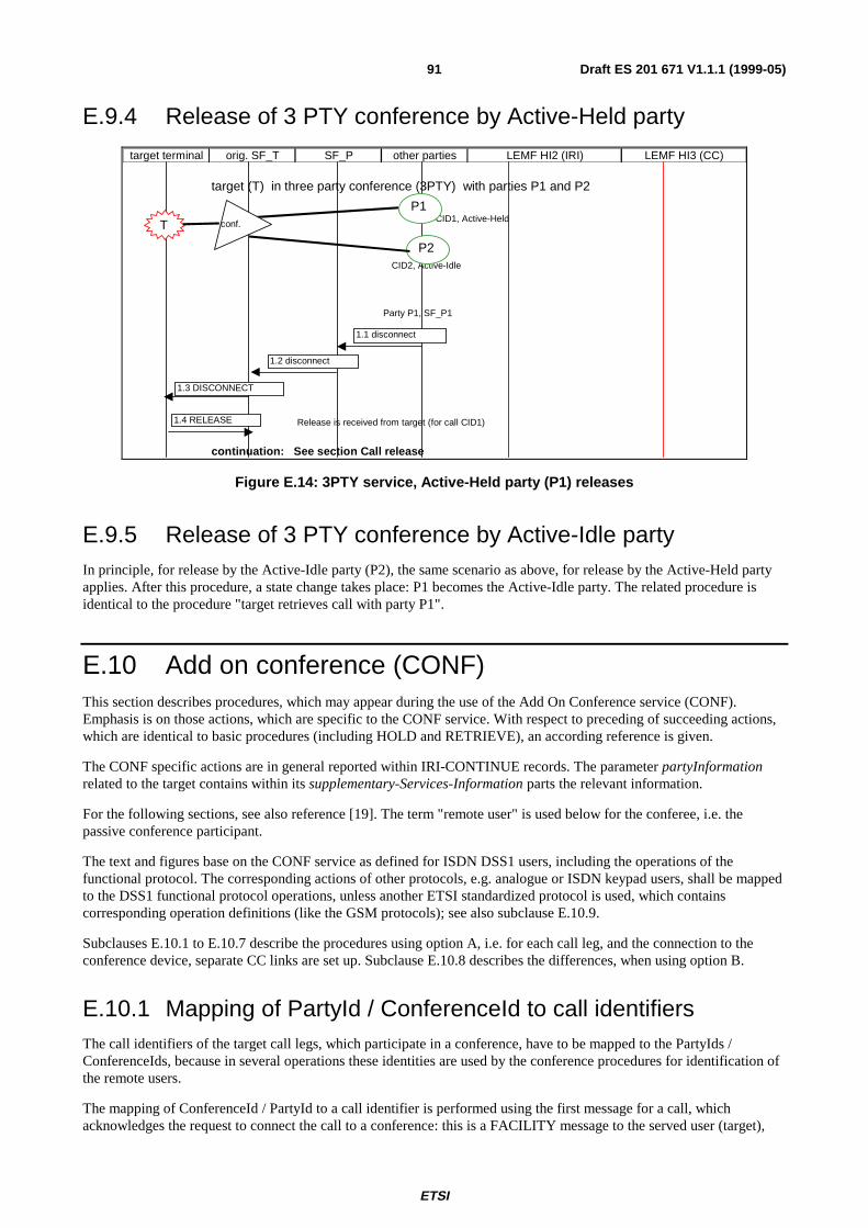
ETSI
Draft ES 201 671 V1.1.1 (1999-05)91
E.9.4 Release of 3 PTY conference by Active-Held party
target terminal orig. SF_T SF_P other parties LEMF HI2 (IRI) LEMF HI3 (CC)
target (T) in three party conference (3PTY) with parties P1 and P2
CID1, Active-Held
CID2, Active-Idle
Party P1, SF_P1
Release is received from target (for call CID1)
continuation: See section Call release
T
P2
P1conf.
1.1 disconnect
1.2 disconnect
1.3 DISCONNECT
1.4 RELEASE
Figure E.14: 3PTY service, Active-Held party (P1) releases
E.9.5 Release of 3 PTY conference by Active-Idle partyIn principle, for release by the Active-Idle party (P2), the same scenario as above, for release by the Active-Held partyapplies. After this procedure, a state change takes place: P1 becomes the Active-Idle party. The related procedure isidentical to the procedure "target retrieves call with party P1".
E.10 Add on conference (CONF)This section describes procedures, which may appear during the use of the Add On Conference service (CONF).Emphasis is on those actions, which are specific to the CONF service. With respect to preceding of succeeding actions,which are identical to basic procedures (including HOLD and RETRIEVE), an according reference is given.
The CONF specific actions are in general reported within IRI-CONTINUE records. The parameter partyInformationrelated to the target contains within its supplementary-Services-Information parts the relevant information.
For the following sections, see also reference [19]. The term "remote user" is used below for the conferee, i.e. thepassive conference participant.
The text and figures base on the CONF service as defined for ISDN DSS1 users, including the operations of thefunctional protocol. The corresponding actions of other protocols, e.g. analogue or ISDN keypad users, shall be mappedto the DSS1 functional protocol operations, unless another ETSI standardized protocol is used, which containscorresponding operation definitions (like the GSM protocols); see also subclause E.10.9.
Subclauses E.10.1 to E.10.7 describe the procedures using option A, i.e. for each call leg, and the connection to theconference device, separate CC links are set up. Subclause E.10.8 describes the differences, when using option B.
E.10.1 Mapping of PartyId / ConferenceId to call identifiersThe call identifiers of the target call legs, which participate in a conference, have to be mapped to the PartyIds /ConferenceIds, because in several operations these identities are used by the conference procedures for identification ofthe remote users.
The mapping of ConferenceId / PartyId to a call identifier is performed using the first message for a call, whichacknowledges the request to connect the call to a conference: this is a FACILITY message to the served user (target),
ETSI
Draft ES 201 671 V1.1.1 (1999-05)92
containing a facility IE with the beginCONF return result component (for the case of beginning a conference from anactive call) or the AddCONF return result component (for adding a party to an existing conference device) ,respectively. The call references of these messages identify the call leg, they can be used as a link to the call identifier.
The call reference of a call leg is released after adding the leg to the conference, but its call identifier (CID1, 2 …) shallbe kept. The call reference of the first message setting up the conference (containing the beginCONF invoke component)is not released. It maps always to the call identifier CID-CONF.
E.10.2 Beginning a conference from the Idle call stateFor beginning a conference from the Idle call state, a SETUP message is sent by the target (call reference CR-CONF),with a beginCONF invoke component. After sending the acknowledgment to the served user (beginCONF return resultcomponent within a CONNECT message), the beginCONF invoke component shall be included in an IRI-BEGINrecord. The component shall contain the ConferenceId parameter. A new call identifier value is assigned (CID-CONF),identifying the connection target - conference device (used for the conference sum signal). The reception of thebeginCONF invoke component by the LEMF indicates the successful CONF establishment; unsuccessful attempts(resulting at the user access in return error or reject components) need not to be reported (general principle, see alsosubclause 10.3).
target terminal orig. SF_T SF_P other parties LEMF HI2 (IRI) LEMF HI3 (CC)
target T
Facility I.E. received with: BeginCONF invokeCall reference: CR-CONF
The following actions are performed, if the conference can be established
returned with: BeginCONF return resultPar.: ConfernceId
CID-CONFfor conference leg
call identifier CID-CONF
no terminating party information
service information:
Facility IE: BeginCONF invoke, incl. ConferenceId
1.2 CONNECT
1.4 IRI-BEGIN
1.3 set up CC inks
T
1.1 SETUP
T conferencedevice
1.5 CC links connected
Figure E.15: Add-on Conference, target starts conference from the idle call state
E.10.3 Beginning a conference from the Active call stateFor beginning a conference from the Active call state, a FACILTY message with a beginCONF invoke component issent by the target, using the call reference of the active call (CR1). After sending the acknowledgment to the served user,a beginCONF return result component within a FACILITY message, the beginCONF invoke component shall beincluded in an IRI-BEGIN record. The component shall contain the ConferenceId parameter and the PartyId (P1) of the
ETSI
Draft ES 201 671 V1.1.1 (1999-05)93
call leg CIDl. A new call identifier value shall be assigned (CID-CONF), identifying the connection target - conferencedevice (used for the conference sum signal).
target terminal orig. SF_T SF_P other parties LEMF HI2 (IRI) LEMF HI3 (CC)
target T has an Active Idle or Active Held connection with at least one other party (P1, CID1)
Facility IE received w ith: BeginCONF invoke
Call Reference: CR1
The following actions are performed, if the conf. can be established
returned w ith: BeginCONF return result
Par.: PartyId P1
Par.: ConfernceId
CID-CONF
for leg of conference
call identif ier CID-CONF device
service information
Facility I.E.: BeginCONF invoke incl. ConferenceId, PartyId P1
1.4 IRI-BEGIN
1.3 set up CC links
2.1 CC links connected
T P1
1.1 FACILITY
T P1conferencedevice
1.2 FACILITY
Figure E.16: Add-on Conference, target starts conference from the active call state
E.10.4 Adding a remote userFor adding a remote user (party x) to an existing conference, a FACILITY message with a AddCONF invoke componentis sent by the target, using the call reference of the call to be added (CR1); it includes a ConferenceId parameter. Thefollowing acknowledgement (a FACILITY message) contains a beginCONF return result component, with a PartyIdparameter. The call identifier for the added call is CID1.
NOTE: After adding the call to the conference, its call reference CR1 is released, but its call identifier CID1 iskept, for use in further records relating to this remote party connection, and to point to the CC links (theyare not used, while the party is in the conference).
ETSI
Draft ES 201 671 V1.1.1 (1999-05)94
target terminal orig. SF_T SF_P other parties LEMF HI2 (IRI) LEMF HI3 (CC)
target T has and a conference established, and an Active Idle or Active Held connection with at least one other party (P1, CID1) target may or may not be connected to the conference
Active Held
Facility I.E. received with: AddCONF invoke
Call Reference: CR1
Par.: ConfernceId
returned with: AddCONF return result
Par.: PartyId P1
call identifier CID1
Facility I.E.: AddCONF invoke, ConferenceID, PartyId P1
CR1
CR1
Release of CR1 is not reportedThe CC call related to the original call T - P1 stay switched, but is not used (option A)
1.2 DISCONNECT
1.3 IRI-CONTINUE
1.1 FACILITY
T P1
2.1 RELEASE
2.2 RELEASE COMPLETE
T P1
conferencedevice
conferencedevice
Figure E.17: Add-on Conference, target adds a call (remote user) to the conference
E.10.5 Splitting a remote userIn case of splitting a remote user, and (simultaneously) setting up a private conversation to it, a SETUP message isreceived from the target, using a new call reference; it contains a facility IE with a SplitCONF invoke component. Theremote party is identified by the ConferenceId and PartyId parameters of the invoke component.
A CONNECT message is sent to the target, to confirm the operation. The SplitCONF invoke component shall be sentwithin an IRI-CONTINUE record to the LEMF.
The call identifier value used for the IRI record and the related CC links, respectively, is the value, which has beenassigned to this call leg, when the call to the remote party has been originally set up (CID1).
ETSI
Draft ES 201 671 V1.1.1 (1999-05)95
target terminal target SN other SN_P other party LEMF HI2 (IRI) LEMF HI3 (CC)
The Party P1 is split
Facility I.E. received w ith: splitCONF invokePar.: PartyId P1Par.: ConferenceId
PartyId P1 released
returned w ith: splitCONF return result
call identif ier CID1 Facility I.E.: splitCONF invoke, ConferenceID, PartyId P1
split, private conversation with T
1.1 SETUP
1.2 CONNECT
1.3 IRI-CONTINUE
T P1
T P1
conferencedevice
conferencedevice
Figure E.18: Add-on Conference, target splits a call (remote user) from the conference
E.10.6 Further actions during a conferenceThe actions isolate, reattach, split, drop and remote party disconnected are reported in IRI-CONTINUE records. Theapplicable call identifier has to be determined via the PartyId. The figure below illustrates the procedure for isolating aparty from the conference.
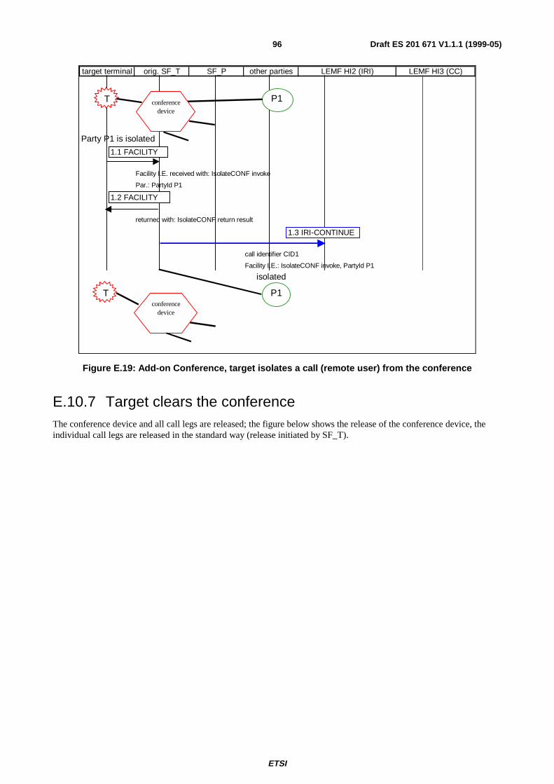
ETSI
Draft ES 201 671 V1.1.1 (1999-05)96
target terminal orig. SF_T SF_P other parties LEMF HI2 (IRI) LEMF HI3 (CC)
Party P1 is isolated
Facility I.E. received with: IsolateCONF invoke
Par.: PartyId P1
returned with: IsolateCONF return result
call identifier CID1
Facility I.E.: IsolateCONF invoke, PartyId P1
isolated
1.2 FACILIT Y
1.3 IRI-CONT INUE
1.1 FACILIT Y
T P1
T P1
conferencedevice
conferencedevice
Figure E.19: Add-on Conference, target isolates a call (remote user) from the conference
E.10.7 Target clears the conferenceThe conference device and all call legs are released; the figure below shows the release of the conference device, theindividual call legs are released in the standard way (release initiated by SF_T).
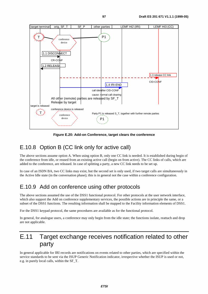
ETSI
Draft ES 201 671 V1.1.1 (1999-05)97
target terminal orig. SF_T SF_P other parties LEMF HI2 (IRI) LEMF HI3 (CC)
CR-CONF
CID-CONF
call identifier CID-CONF
cause: normal call clearing
All other (remote) parties are released by SF_TRelease by target
target is releasedconference device is released
Party P1 is released S_T, together with further remote parties
1.1 DIS CONNECT
1.4 IRI-END
T P1
T
P1
1.2 RELEAS E
1.3 release CC link
conferencedevice
conferencedevice
Figure E.20: Add-on Conference, target clears the conference
E.10.8 Option B (CC link only for active call)The above sections assume option A. When using option B, only one CC link is needed. It is established during begin ofthe conference from idle, or reused from an existing active call (begin on from active). The CC links of calls, which areadded to the conference, are released. In case of splitting a party, a new CC link needs to be set up.
In case of an ISDN BA, two CC links may exist, but the second set is only used, if two target calls are simultaneously inthe Active Idle state (in the conversation phase); this is in general not the case within a conference configuration.
E.10.9 Add on conference using other protocolsThe above sections assumed the use of the DSS1 functional protocol. For other protocols at the user network interface,which also support the Add on conference supplementary services, the possible actions are in principle the same, or asubset of the DSS1 functions. The resulting information shall be mapped to the Facility information elements of DSS1.
For the DSS1 keypad protocol, the same procedures are available as for the functional protocol.
In general, for analogue users, a conference may only begin from the idle state; the functions isolate, reattach and dropare not applicable.
E.11 Target exchange receives notification related to otherparty
In general applicable for IRI records are notifications on events related to other parties, which are specified within theservice standards to be sent via the ISUP Generic Notification indicator, irrespective whether the ISUP is used or not,e.g. in purely local calls, within the SF_T.
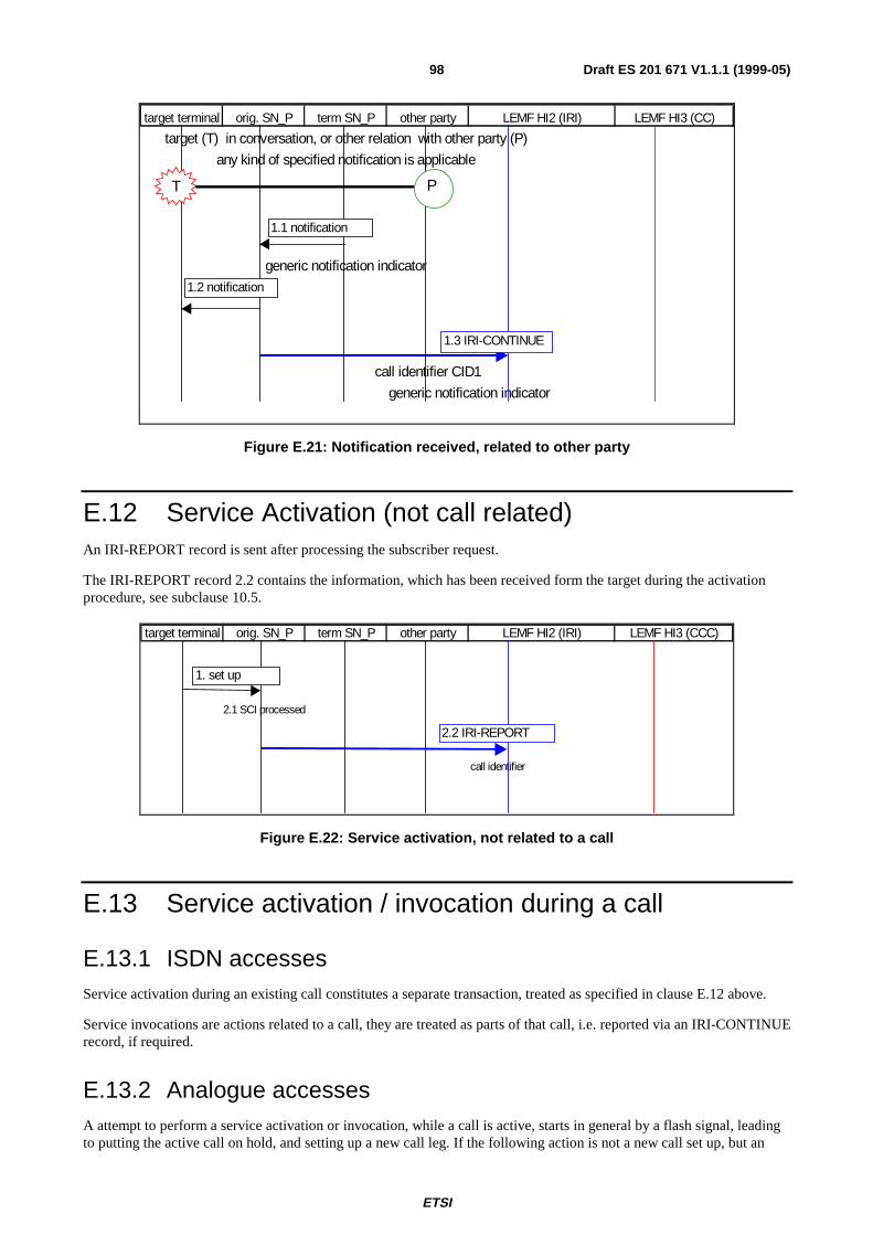
ETSI
Draft ES 201 671 V1.1.1 (1999-05)98
target terminal orig. SN_P term SN_P other party LEMF HI2 (IRI) LEMF HI3 (CC)
target (T) in conversation, or other relation with other party (P)
any kind of specified notification is applicable
generic notification indicator
call identifier CID1
generic notification indicator
1.3 IRI-CONTINUE
T P
1.1 notification
1.2 notification
Figure E.21: Notification received, related to other party
E.12 Service Activation (not call related)An IRI-REPORT record is sent after processing the subscriber request.
The IRI-REPORT record 2.2 contains the information, which has been received form the target during the activationprocedure, see subclause 10.5.
target terminal orig. SN_P term SN_P other party LEMF HI2 (IRI) LEMF HI3 (CCC)
2.1 SCI processed
call identifier
1. set up
2.2 IRI-REPORT
Figure E.22: Service activation, not related to a call
E.13 Service activation / invocation during a call
E.13.1 ISDN accessesService activation during an existing call constitutes a separate transaction, treated as specified in clause E.12 above.
Service invocations are actions related to a call, they are treated as parts of that call, i.e. reported via an IRI-CONTINUErecord, if required.
E.13.2 Analogue accessesA attempt to perform a service activation or invocation, while a call is active, starts in general by a flash signal, leadingto putting the active call on hold, and setting up a new call leg. If the following action is not a new call set up, but an
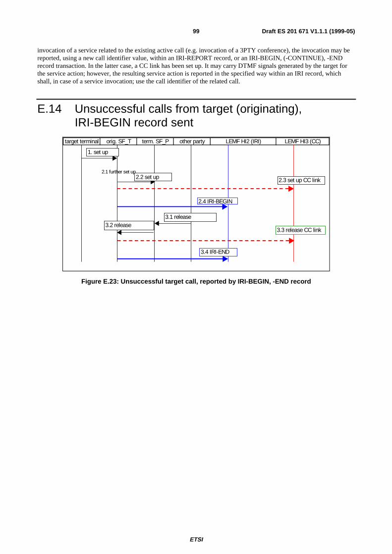
ETSI
Draft ES 201 671 V1.1.1 (1999-05)99
invocation of a service related to the existing active call (e.g. invocation of a 3PTY conference), the invocation may bereported, using a new call identifier value, within an IRI-REPORT record, or an IRI-BEGIN, (-CONTINUE), -ENDrecord transaction. In the latter case, a CC link has been set up. It may carry DTMF signals generated by the target forthe service action; however, the resulting service action is reported in the specified way within an IRI record, whichshall, in case of a service invocation; use the call identifier of the related call.
E.14 Unsuccessful calls from target (originating),IRI-BEGIN record sent
target terminal orig. SF_T term. SF_P other party LEMF HI2 (IRI) LEMF HI3 (CC)
2.1 further set up
1. set up
2.4 IRI-BEGIN
2.3 set up CC link2.2 set up
3.1 release
3.4 IRI-END
3.3 release CC link3.2 release
Figure E.23: Unsuccessful target call, reported by IRI-BEGIN, -END record
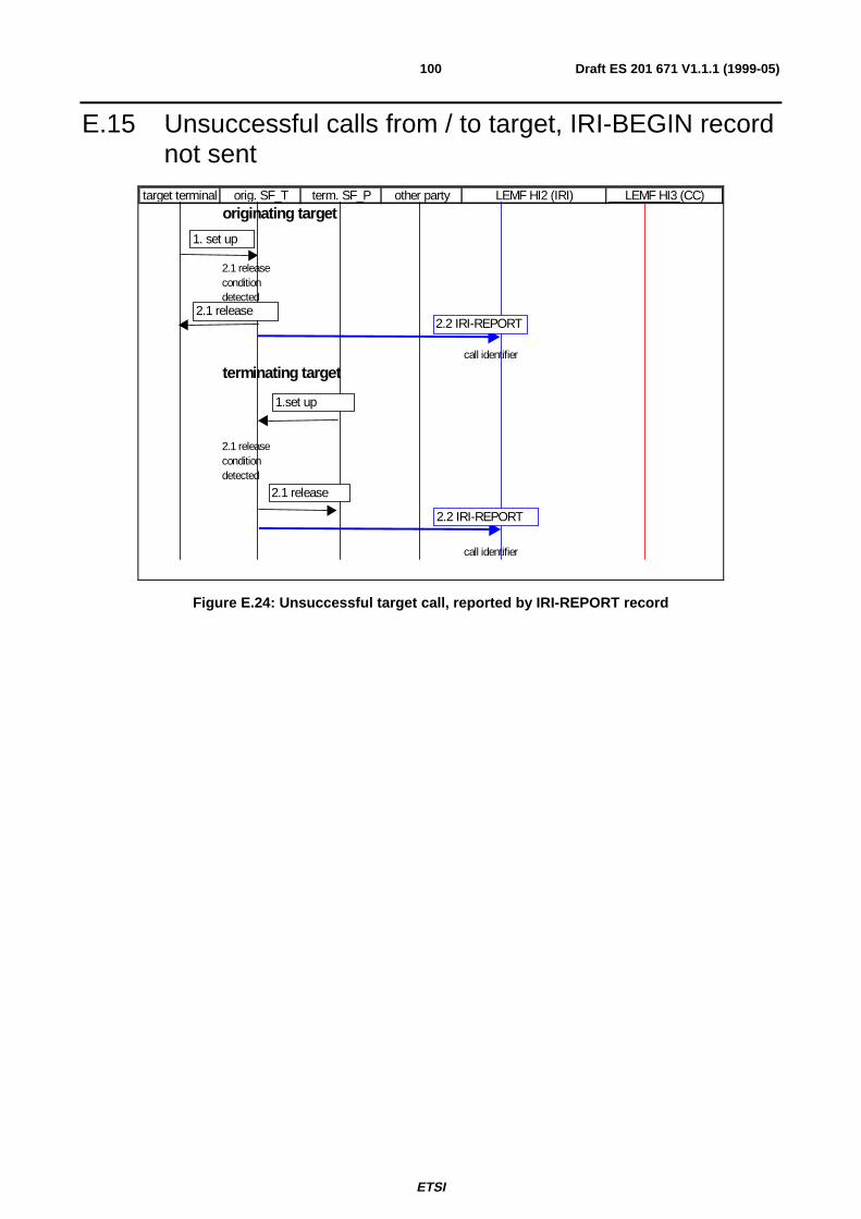
ETSI
Draft ES 201 671 V1.1.1 (1999-05)100
E.15 Unsuccessful calls from / to target, IRI-BEGIN recordnot sent
target terminal orig. SF_T term. SF_P other party LEMF HI2 (IRI) LEMF HI3 (CC)
originating target
2.1 release condition detected
call identifier
terminating target
2.1 release condition detected
call identifier
1. set up
2.2 IRI-REPORT2.1 release
1.set up
2.1 release
2.2 IRI-REPORT
Figure E.24: Unsuccessful target call, reported by IRI-REPORT record
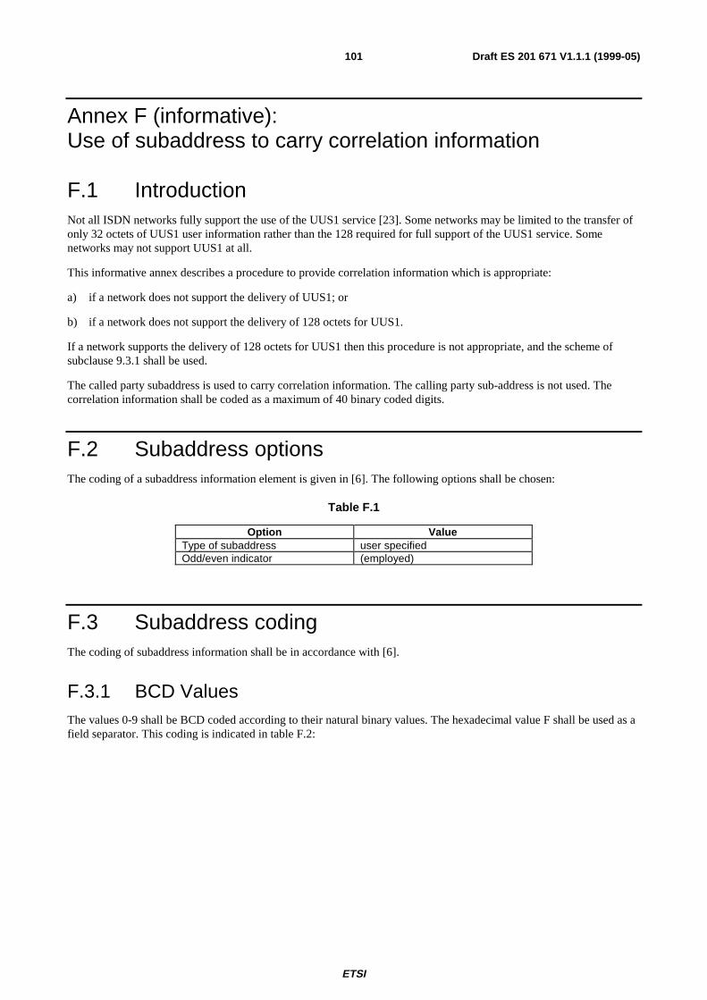
ETSI
Draft ES 201 671 V1.1.1 (1999-05)101
Annex F (informative):Use of subaddress to carry correlation information
F.1 IntroductionNot all ISDN networks fully support the use of the UUS1 service [23]. Some networks may be limited to the transfer ofonly 32 octets of UUS1 user information rather than the 128 required for full support of the UUS1 service. Somenetworks may not support UUS1 at all.
This informative annex describes a procedure to provide correlation information which is appropriate:
a) if a network does not support the delivery of UUS1; or
b) if a network does not support the delivery of 128 octets for UUS1.
If a network supports the delivery of 128 octets for UUS1 then this procedure is not appropriate, and the scheme ofsubclause 9.3.1 shall be used.
The called party subaddress is used to carry correlation information. The calling party sub-address is not used. Thecorrelation information shall be coded as a maximum of 40 binary coded digits.
F.2 Subaddress optionsThe coding of a subaddress information element is given in [6]. The following options shall be chosen:
Table F.1
Option ValueType of subaddress user specifiedOdd/even indicator (employed)
F.3 Subaddress codingThe coding of subaddress information shall be in accordance with [6].
F.3.1 BCD ValuesThe values 0-9 shall be BCD coded according to their natural binary values. The hexadecimal value F shall be used as afield separator. This coding is indicated in table F.2:
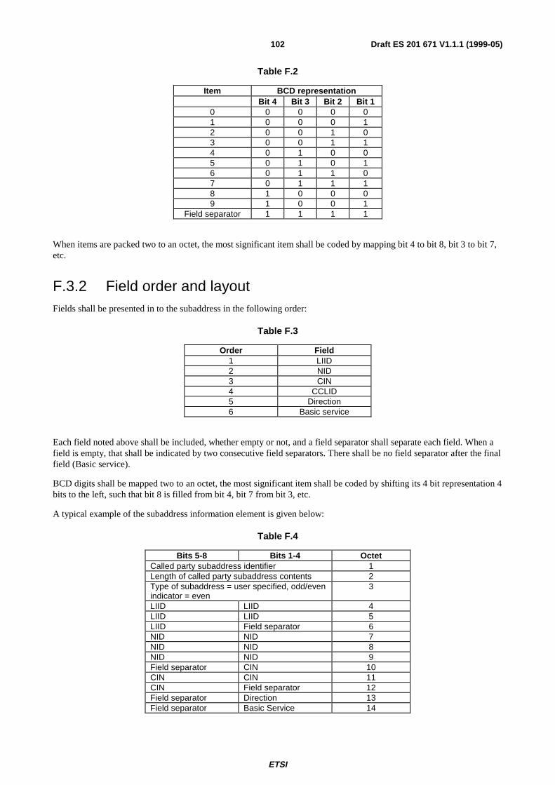
ETSI
Draft ES 201 671 V1.1.1 (1999-05)102
Table F.2
Item BCD representationBit 4 Bit 3 Bit 2 Bit 1
0 0 0 0 01 0 0 0 12 0 0 1 03 0 0 1 14 0 1 0 05 0 1 0 16 0 1 1 07 0 1 1 18 1 0 0 09 1 0 0 1
Field separator 1 1 1 1
When items are packed two to an octet, the most significant item shall be coded by mapping bit 4 to bit 8, bit 3 to bit 7,etc.
F.3.2 Field order and layoutFields shall be presented in to the subaddress in the following order:
Table F.3
Order Field1 LIID2 NID3 CIN4 CCLID5 Direction6 Basic service
Each field noted above shall be included, whether empty or not, and a field separator shall separate each field. When afield is empty, that shall be indicated by two consecutive field separators. There shall be no field separator after the finalfield (Basic service).
BCD digits shall be mapped two to an octet, the most significant item shall be coded by shifting its 4 bit representation 4bits to the left, such that bit 8 is filled from bit 4, bit 7 from bit 3, etc.
A typical example of the subaddress information element is given below:
Table F.4
Bits 5-8 Bits 1-4 OctetCalled party subaddress identifier 1Length of called party subaddress contents 2Type of subaddress = user specified, odd/evenindicator = even
3
LIID LIID 4LIID LIID 5LIID Field separator 6NID NID 7NID NID 8NID NID 9Field separator CIN 10CIN CIN 11CIN Field separator 12Field separator Direction 13Field separator Basic Service 14
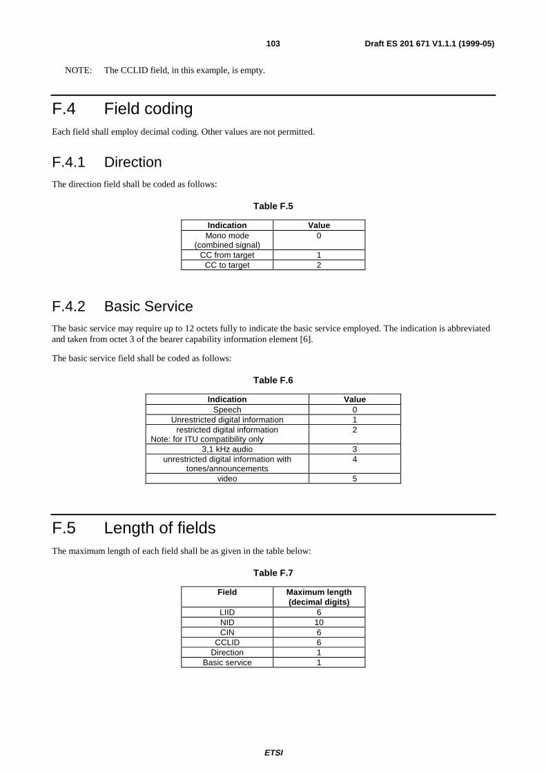
ETSI
Draft ES 201 671 V1.1.1 (1999-05)103
NOTE: The CCLID field, in this example, is empty.
F.4 Field codingEach field shall employ decimal coding. Other values are not permitted.
F.4.1 DirectionThe direction field shall be coded as follows:
Table F.5
Indication ValueMono mode
(combined signal)0
CC from target 1CC to target 2
F.4.2 Basic ServiceThe basic service may require up to 12 octets fully to indicate the basic service employed. The indication is abbreviatedand taken from octet 3 of the bearer capability information element [6].
The basic service field shall be coded as follows:
Table F.6
Indication ValueSpeech 0
Unrestricted digital information 1restricted digital information
Note: for ITU compatibility only2
3,1 kHz audio 3unrestricted digital information with
tones/announcements4
video 5
F.5 Length of fieldsThe maximum length of each field shall be as given in the table below:
Table F.7
Field Maximum length(decimal digits)
LIID 6NID 10CIN 6
CCLID 6Direction 1
Basic service 1

ETSI
Draft ES 201 671 V1.1.1 (1999-05)104
BibliographyThe following material, though not specifically referenced in the body of the present document (or not publiclyavailable), gives supporting information.
ETS 300 121: "Integrated Services Digital Network (ISDN); Application of the ISDN User Part (ISUP) of CCITTSignalling System No. 7 for international ISDN interconnections (ISUP version 1)".
EN 300 052-1: "Integrated Services Digital Network (ISDN); Multiple Subscriber Number (MSN) supplementaryservice; Digital Subscriber Signalling System No. one (DSS1) protocol; Part 1: Protocol specification".
EN 300 055-1: "Integrated Services Digital Network (ISDN); Terminal Portability (TP) supplementary service; DigitalSubscriber Signalling System No. one (DSS1) protocol; Part 1: Protocol specification".
EN 300 058-1: "Integrated Services Digital Network (ISDN); Call Waiting (CW) supplementary service; DigitalSubscriber Signalling System No. one (DSS1) protocol; Part 1: Protocol specification".
EN 300 064-1: "Integrated Services Digital Network (ISDN); Direct Dialling In (DDI) supplementary service; DigitalSubscriber Signalling System No. one (DSS1) protocol; Part 1: Protocol specification".
EN 300 092-1 including Amendment 2: "Integrated Services Digital Network (ISDN); Calling Line IdentificationPresentation (CLIP) supplementary service; Digital Subscriber Signalling System No. one (DSS1) protocol; Part 1:Protocol specification".
EN 300 093-1: "Integrated Services Digital Network (ISDN); Calling Line Identification Restriction (CLIR)supplementary service; Digital Subscriber Signalling System No. one (DSS1) protocol; Part 1: Protocol specification".
EN 300 141-1: "Integrated Services Digital Network (ISDN); Call Hold (HOLD) supplementary service; DigitalSubscriber Signalling System No. one (DSS1) protocol; Part 1: Protocol specification".
EN 300 210-1: "Integrated Services Digital Network (ISDN); Freephone (FPH) supplementary service; DigitalSubscriber Signalling System No. one (DSS1) protocol; Part 1: Protocol specification".
EN 300 359-1: "Integrated Services Digital Network (ISDN); Completion of Calls to Busy Subscriber (CCBS)supplementary service; Digital Subscriber Signalling System No. one (DSS1) protocol; Part 1: Protocol specification".
EN 300 745-1: "Integrated Services Digital Network (ISDN); Message Waiting Indication (MWI) supplementaryservice; Digital Subscriber Signalling System No. one (DSS1) protocol; Part 1: Protocol specification".
EN 301 001-1 (V1.1): "Integrated Services Digital Network (ISDN); Outgoing Call Barring (OCB) supplementaryservices; Digital Subscriber Signalling System No. one (DSS1) protocol; Part 1: Protocol specification".
EN 301 065-1 (V1.1): "Integrated Services Digital Network (ISDN); Completion of Calls on No Reply (CCNR)supplementary service; Digital Subscriber Signalling System No. one (DSS1) protocol; Part 1: Protocol specification".
ITU-T Recommendation Q.699: "Interworking between ISDN access and non-ISDN access over ISDN User Part ofSignalling System No. 7".
ITU-T Recommendation I.210: "Principles of telecommunication services supported by an ISDN and the means todescribe them".

ETSI
Draft ES 201 671 V1.1.1 (1999-05)105
History
Document history
V1.1.1 May 1999 Membership Approval Procedure MV 9927: 1999-05-04 to 1999-07-02