Embed Size (px)
Citation preview

Operator’s ManualIMPORTANT: Read this manual carefully. It contains information about yoursafety and the safety of others. Also become familiar with the controls andtheir proper use before you operate the product.
FORM NO. 3319–612
Wheel Horse
267H
Lawn & GardenTractor
Model No. 72085 – 8900001 & Up
The Toro Company – 1997All Rights Reserved
IntroductionThank you for purchasing a Toro product.
All of us at Toro want you to be completely satisfiedwith your new product, so feel free to contact yourlocal Authorized Service Dealer for help with service,genuine replacement parts, or other information youmay require.
Whenever you contact your Authorized ServiceDealer or the factory, always know the model andserial numbers of your product. These numbers willhelp the Service Dealer or Service Representativeprovide exact information about your specificproduct. You will find the model and serial numberplate located in a unique place on the product asshown below.
1
1202
1. Model and Serial Number Plate (under the seat)
For your convenience, write the product model andserial numbers in the space below.
Model No:
Serial No.
Read this manual carefully to learn how to operateand maintain your product correctly. Reading thismanual will help you and others avoid personal injuryand damage to the product. Although we design,produce and market safe, state-of-the-art products,you are responsible for using the product properlyand safely. You are also responsible for trainingpersons, who you allow to use the product, about safeoperation.
The warning system in this manual identifiespotential hazards and has special safety messages thathelp you and others avoid personal injury, even death.DANGER, WARNING and CAUTION are signalwords used to identify the level of hazard. However,regardless of the hazard, be extremely careful.
DANGER signals an extreme hazard that will causeserious injury or death if the recommendedprecautions are not followed.
WARNING signals a hazard that may cause seriousinjury or death if the recommended precautions arenot followed.
CAUTION signals a hazard that may cause minor ormoderate injury if the recommended precautions arenot followed.
Two other words are also used to highlightinformation. “Important” calls attention to specialmechanical information and “Note” emphasizesgeneral information worthy of special attention.
The left and right side of the machine is determinedby sitting on the seat in the normal operator’sposition.
The engine exhaust from this productcontains chemicals known to the State ofCalifornia to cause cancer, birth defects,
or other reproductive harm.
1
ContentsPage
Safety 2. . . . . . . . . . . . . . . . . . . . . . . . . . . . . . . . .
Safe Operating Practices 2. . . . . . . . . . . . . .
Slope Chart 5. . . . . . . . . . . . . . . . . . . . . . . . .
Safety and Instruction Decals 7. . . . . . . . . .
Gasoline and Oil 8. . . . . . . . . . . . . . . . . . . . . . . .
Recommended Gasoline 8. . . . . . . . . . . . . .
Stabilizer/Conditioner 8. . . . . . . . . . . . . . . .
Filling the Fuel Tank 8. . . . . . . . . . . . . . . . .
Check Engine Oil Level 8. . . . . . . . . . . . . . .
Operation 9. . . . . . . . . . . . . . . . . . . . . . . . . . . . . .
Think Safety First 9. . . . . . . . . . . . . . . . . . .
Controls 9. . . . . . . . . . . . . . . . . . . . . . . . . . .
Parking Brake 9. . . . . . . . . . . . . . . . . . . . . . .
Starting and Stopping the Engine 10. . . . . . .
Operating the Power Take Off (PTO) 11. . . .
The Safety Interlock System 11. . . . . . . . . . .
Indicator Control Module 12. . . . . . . . . . . . .
Hourmeter 12. . . . . . . . . . . . . . . . . . . . . . . . .
Driving Forward or Backward 13. . . . . . . . . .
Stopping the Machine 13. . . . . . . . . . . . . . . .
Attachment Lift Lever 14. . . . . . . . . . . . . . . .
Adjusting Dial-A-Height 14. . . . . . . . . . . . . .
Positioning the Seat 15. . . . . . . . . . . . . . . . . .
Page
Headlights 15. . . . . . . . . . . . . . . . . . . . . . . . .
Positioning the Tilt Steering Wheel 15. . . . . .
Using the Cruise Control 16. . . . . . . . . . . . . .
Pushing the Machine by Hand 16. . . . . . . . . .
Maintenance 17. . . . . . . . . . . . . . . . . . . . . . . . . . . .
Service Interval Chart 17. . . . . . . . . . . . . . . .
Air Cleaner 18. . . . . . . . . . . . . . . . . . . . . . . . .
Engine Oil 20. . . . . . . . . . . . . . . . . . . . . . . . .
Spark Plug 22. . . . . . . . . . . . . . . . . . . . . . . . .
Greasing and Lubrication 23. . . . . . . . . . . . . .
Tire Pressure 23. . . . . . . . . . . . . . . . . . . . . . . .
Brake 24. . . . . . . . . . . . . . . . . . . . . . . . . . . . .
Fuel Tank 25. . . . . . . . . . . . . . . . . . . . . . . . . .
Fuel Filter 26. . . . . . . . . . . . . . . . . . . . . . . . . .
Front Wheel Toe-In 27. . . . . . . . . . . . . . . . . .
Transaxle Fluid 28. . . . . . . . . . . . . . . . . . . . . .
Fuse 28. . . . . . . . . . . . . . . . . . . . . . . . . . . . . .
Headlights 29. . . . . . . . . . . . . . . . . . . . . . . . .
Battery 30. . . . . . . . . . . . . . . . . . . . . . . . . . . .
Wiring Diagram 33. . . . . . . . . . . . . . . . . . . . .
Cleaning and Storage 34. . . . . . . . . . . . . . . . .
Troubleshooting 35. . . . . . . . . . . . . . . . . . . . . . . . .
Warranty Back Cover. . . . . . . . . . . . . . . . . . . . . . . . . .
2
SafetyThis machine meets or exceeds the B71.1–1990specifications of the American National StandardsInstitute, in effect at the time of production.However, improper use or maintenance by theoperator or owner can result in injury. To reducethe potential for injury, comply with these safetyinstructions and always pay attention to the safetyalert symbol, which means CAUTION,WARNING, or DANGER—“personal safetyinstruction.” Failure to comply with theinstruction may result in personal injury or death.
Safe Operating Practices
This product is capable of amputating hands and feetand throwing objects. Always follow all safetyinstructions to avoid serious injury or death.
POTENTIAL HAZARD• Engine exhaust contains carbon monoxide,
which is an odorless, deadly poison.
WHAT CAN HAPPEN• Carbon monoxide can kill you and is also
known to the State of California to causebirth defects.
HOW TO AVOID THE HAZARD• Do not run engine indoors or in an enclosed
area.
General Operation
1. Read, understand, and follow all instructions inthe operator’s manual and on the machine beforestarting.
2. Allow only responsible adults who are familiarwith the instructions to operate the machine.
3. Clear the area of objects such as rocks, toys,wire, etc., which could be picked up and thrownby the blade.
4. Be sure the area is clear of other people beforemowing. Stop the machine if anyone enters thearea.
5. Never carry passengers.
6. Do not mow in reverse unless absolutelynecessary. Always look down and behind beforeand while backing.
7. Be aware of the mower discharge direction anddo not point it at anyone. Do not operate themower without either the entire grass catcher orthe guard in place.
8. Slow down before turning. Sharp turns on anyterrain may cause loss of control.
9. Never leave a running machine unattended.Always turn off blades, set parking brake, stopengine, and remove key before dismounting.
10. Turn off blades when not mowing.
11. Keep hands, feet, hair and loose clothing awayfrom attachment discharge area, underside ofmower and any moving parts while engine isrunning.
12. Stop the engine before removing the grasscatcher or unclogging the chute.
Safety
3
13. Mow only in daylight or good artificial light.
14. Do not operate the machine while under theinfluence of alcohol or drugs.
15. Watch for traffic when operating near or crossingroadways.
16. Use extra care when loading or unloading themachine onto a trailer or truck.
17. Do not touch equipment or attachment partswhich may be hot from operation. Allow to coolbefore attempting to maintain, adjust or service.
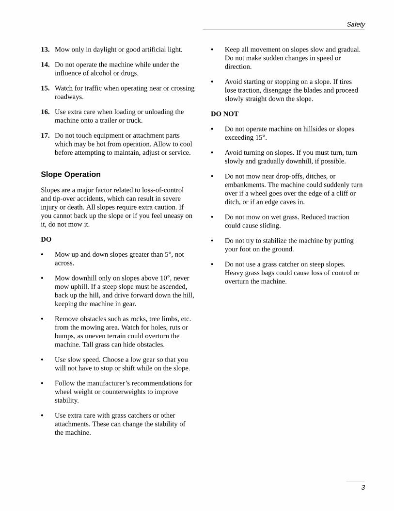
Slope Operation
Slopes are a major factor related to loss-of-controland tip-over accidents, which can result in severeinjury or death. All slopes require extra caution. Ifyou cannot back up the slope or if you feel uneasy onit, do not mow it.
DO
• Mow up and down slopes greater than 5°, notacross.
• Mow downhill only on slopes above 10°, nevermow uphill. If a steep slope must be ascended,back up the hill, and drive forward down the hill,keeping the machine in gear.
• Remove obstacles such as rocks, tree limbs, etc.from the mowing area. Watch for holes, ruts orbumps, as uneven terrain could overturn themachine. Tall grass can hide obstacles.
• Use slow speed. Choose a low gear so that youwill not have to stop or shift while on the slope.
• Follow the manufacturer’s recommendations forwheel weight or counterweights to improvestability.
• Use extra care with grass catchers or otherattachments. These can change the stability ofthe machine.
• Keep all movement on slopes slow and gradual.Do not make sudden changes in speed ordirection.
• Avoid starting or stopping on a slope. If tireslose traction, disengage the blades and proceedslowly straight down the slope.
DO NOT
• Do not operate machine on hillsides or slopesexceeding 15°.
• Avoid turning on slopes. If you must turn, turnslowly and gradually downhill, if possible.
• Do not mow near drop-offs, ditches, orembankments. The machine could suddenly turnover if a wheel goes over the edge of a cliff orditch, or if an edge caves in.
• Do not mow on wet grass. Reduced tractioncould cause sliding.
• Do not try to stabilize the machine by puttingyour foot on the ground.
• Do not use a grass catcher on steep slopes.Heavy grass bags could cause loss of control oroverturn the machine.

Safety
4
Children
Tragic accidents can occur if the operator is not alertto the presence of children. Children are oftenattracted to the machine and the mowing activity.Never assume that children will remain where youlast saw them. The following requirements must befollowed to prevent injury to children.
1. Keep children out of the mowing area and underthe watchful care of another responsible adult.
2. Be alert and turn the machine off if childrenenter the area.
3. Before and while backing, look behind and downfor small children.
4. Never carry children. They may fall off and beseriously injured or interfere with safe machineoperation.
5. Never allow children to operate the machine.
6. Use extra care when approaching blind corners,shrubs, trees, the end of a fence or other objectsthat may obscure vision.
Service
1. Stop the engine and disconnect spark plugwire(s) before performing any service, repairs,maintenance or adjustments.
2. Use extra care when handling gasoline and otherfuels. They are flammable and vapors areexplosive.
A. Use only an approved container.
B. Never remove the gas cap or add fuel whenthe engine is running. Allow the engine tocool before refueling. Do not smoke.
C. Never refuel the machine indoors.
D. Never store the machine or fuel containerinside where there is an open flame, such asnear a water heater or furnace.
3. Never run a machine inside a closed area.
4. Keep nuts and bolts tight, especially the bladeattachment bolts. Keep equipment in goodcondition.
5. Never tamper with safety devices. Check safetysystems for proper operation before each use.
6. Keep the machine free of grass, leaves, or otherdebris build-up. Clean up oil or fuel spillage.Allow the machine to cool before storing.
7. Stop and inspect the equipment if you strike anobject. Repair, if necessary, before restarting.
8. Grass catcher components are subject to wear,damage and deterioration, which could exposemoving parts or allow objects to be thrown.Frequently check components and replace withmanufacturer’s recommended parts, whennecessary.
9. Mower blades are sharp and can cut. Wrap theblade(s) or wear gloves, and use extra cautionwhen servicing them.
10. Use only genuine replacement parts to ensurethat original standards are maintained.
11. Check brake operation frequently. Adjust andservice as required.
12. Battery acid is poisonous and can cause burns.Avoid contact with skin, eyes and clothing.Protect your face, eyes and clothing whenworking with a battery.
13. Battery gases can explode. Keep cigarettes,sparks and flames away from battery.
Safety
5
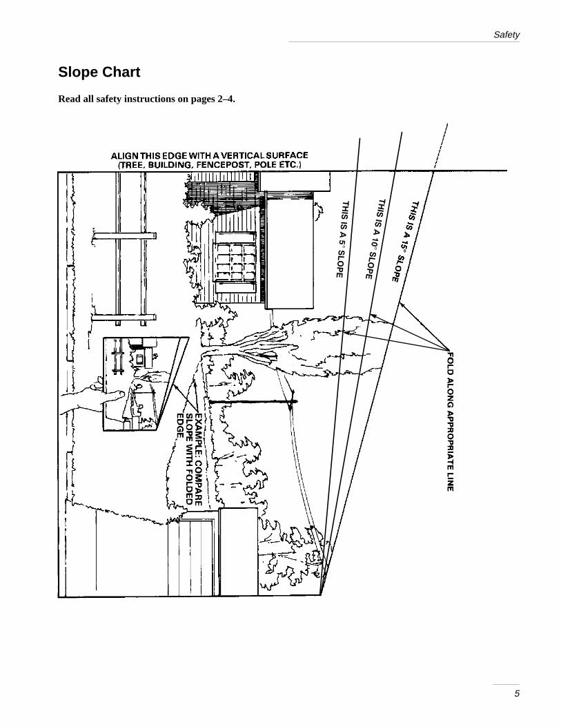
Slope Chart
Read all safety instructions on pages 2–4.

6
Safety
7
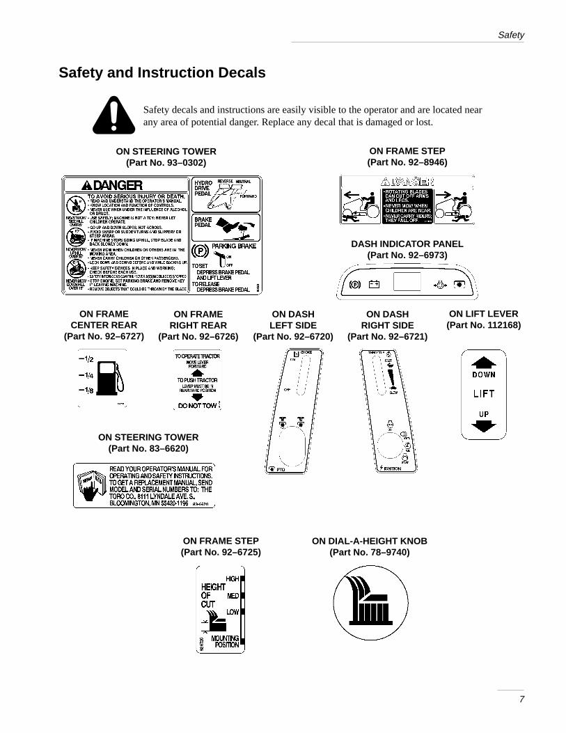
Safety and Instruction Decals
Safety decals and instructions are easily visible to the operator and are located nearany area of potential danger. Replace any decal that is damaged or lost.
ON STEERING TOWER(Part No. 93–0302)
ON DASHLEFT SIDE
(Part No. 92–6720)
ON DASHRIGHT SIDE
(Part No. 92–6721)
ON FRAMERIGHT REAR
(Part No. 92–6726)
ON FRAMECENTER REAR
(Part No. 92–6727)
ON FRAME STEP(Part No. 92–6725)
ON LIFT LEVER(Part No. 112168)
ON DIAL-A-HEIGHT KNOB(Part No. 78–9740)
ON FRAME STEP(Part No. 92–8946)
DASH INDICATOR PANEL(Part No. 92–6973)
ON STEERING TOWER(Part No. 83–6620)
8
Gasoline and OilRecommended Gasoline
Use UNLEADED Regular Gasoline suitable forautomotive use (85 pump octane minimum). Leadedregular gasoline may be used if unleaded regular isnot available.
IMPORTANT: Never use methanol, gasolinecontaining methanol, or gasohol containingmore than 10% ethanol because the fuelsystem could be damaged. Do not mix oil withgasoline.
POTENTIAL HAZARD• In certain conditions gasoline is extremely
flammable and highly explosive.
WHAT CAN HAPPEN• A fire or explosion from gasoline can burn
you, others, and cause property damage.
HOW TO AVOID THE HAZARD• Use a funnel and fill the fuel tank outdoors,
in an open area, when the engine is cold.Wipe up any gasoline that spills.
• Do not fill the fuel tank completely full.Add gasoline to the fuel tank until the levelis 1/4” to 1/2” (6 mm to 13 mm) below thebottom of the filler neck. This empty spacein the tank allows gasoline to expand.
• Never smoke when handling gasoline, andstay away from an open flame or wheregasoline fumes may be ignited by a spark.
• Store gasoline in an approved containerand keep it out of the reach of children.Never buy more than a 30-day supply ofgasoline.
Stabilizer/Conditioner
Add the correct amount of gas stabilizer/conditionerto the gas. Using a stabilizer/conditioner that isisopropyl-based in the machine:
• Keeps gasoline fresh during storage
• Cleans the engine while it runs
• Eliminates gum-like buildup in the fuel system,which causes hard starting
IMPORTANT: Never use fuel additivescontaining methanol or ethanol.
Filling the Fuel Tank
1. Shut the engine off and raise the seat.
2. Clean around the fuel tank cap and remove thecap. Use a funnel and add unleaded regulargasoline to the fuel tank, until the level is 1/4 to1/2 inch (6 mm to 13 mm) below the bottom ofthe filler neck. This space in the tank allowsgasoline to expand. Do not fill the fuel tankcompletely full.
3. Install the fuel tank cap securely. Wipe up anygasoline that may have spilled.
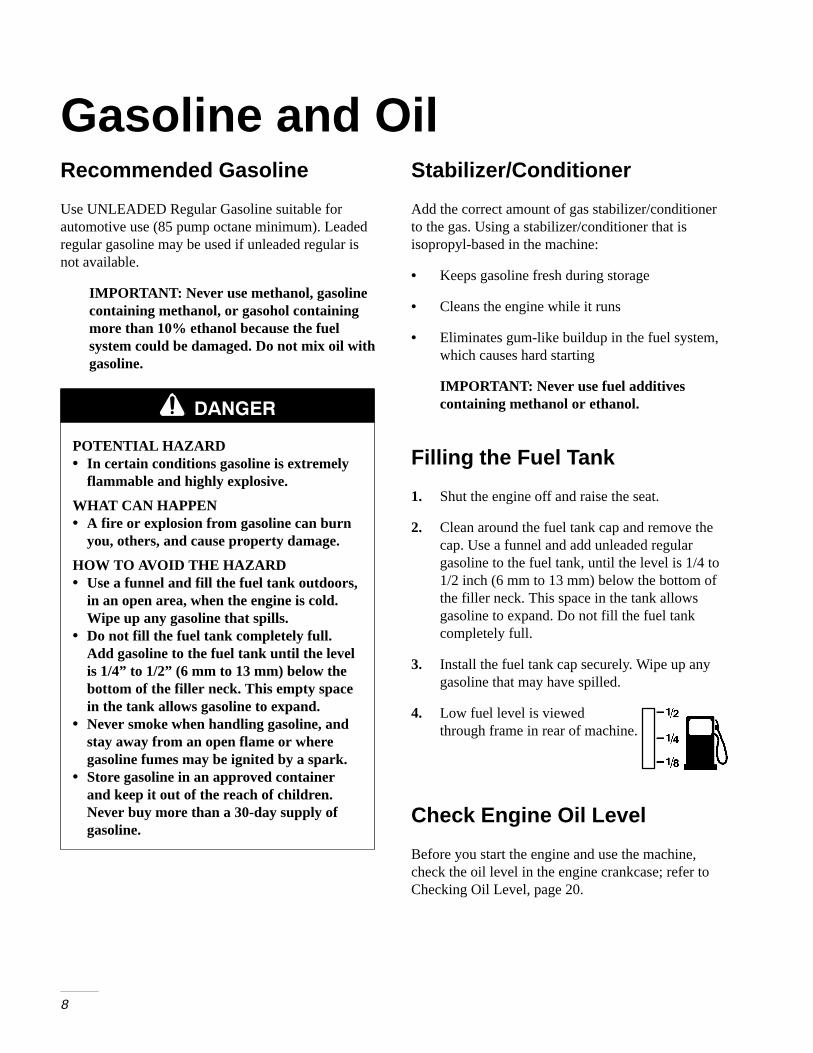
4. Low fuel level is viewed through frame in rear of machine.
Check Engine Oil Level
Before you start the engine and use the machine,check the oil level in the engine crankcase; refer toChecking Oil Level, page 20.
9
OperationThink Safety First
Please carefully read all the safety instructions onpages 2–7. Knowing this information could help you,your family, pets or bystanders avoid injury.
Controls
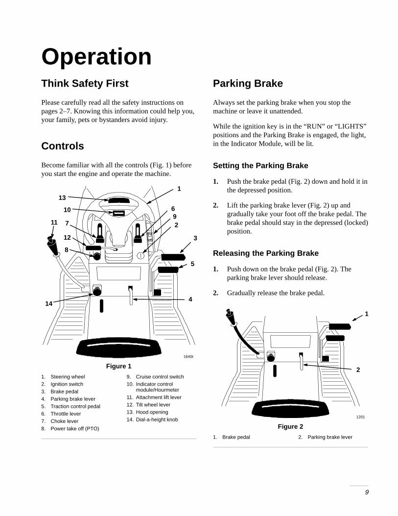
Become familiar with all the controls (Fig. 1) beforeyou start the engine and operate the machine.
2
3
4
8
910
12
1640t
1
6
11
5
14
7
13
Figure 1
1. Steering wheel2. Ignition switch3. Brake pedal4. Parking brake lever5. Traction control pedal6. Throttle lever7. Choke lever8. Power take off (PTO)
9. Cruise control switch10. Indicator control
module/Hourmeter11. Attachment lift lever12. Tilt wheel lever13. Hood opening14. Dial-a-height knob
Parking Brake
Always set the parking brake when you stop themachine or leave it unattended.
While the ignition key is in the “RUN” or “LIGHTS”positions and the Parking Brake is engaged, the light,in the Indicator Module, will be lit.
Setting the Parking Brake
1. Push the brake pedal (Fig. 2) down and hold it inthe depressed position.
2. Lift the parking brake lever (Fig. 2) up andgradually take your foot off the brake pedal. Thebrake pedal should stay in the depressed (locked)position.
Releasing the Parking Brake
1. Push down on the brake pedal (Fig. 2). Theparking brake lever should release.
2. Gradually release the brake pedal.
1
2
1201
Figure 2
1. Brake pedal 2. Parking brake lever
Operation
10
Starting and Stoppingthe Engine
Starting
1. Sit down on the seat.
2. Set the parking brake; refer to Setting theParking Brake, page 9.
Note: The engine will not start unless you setthe parking brake or fully depress thebrake pedal.
3. Push the PTO (power take off) to “OFF”(Fig. 3).
4. Move the choke lever to “ON” (Fig. 3).
Note: An engine that has been running and iswarm may not require step 4.
5. Move throttle lever to “FAST” (Fig. 4).
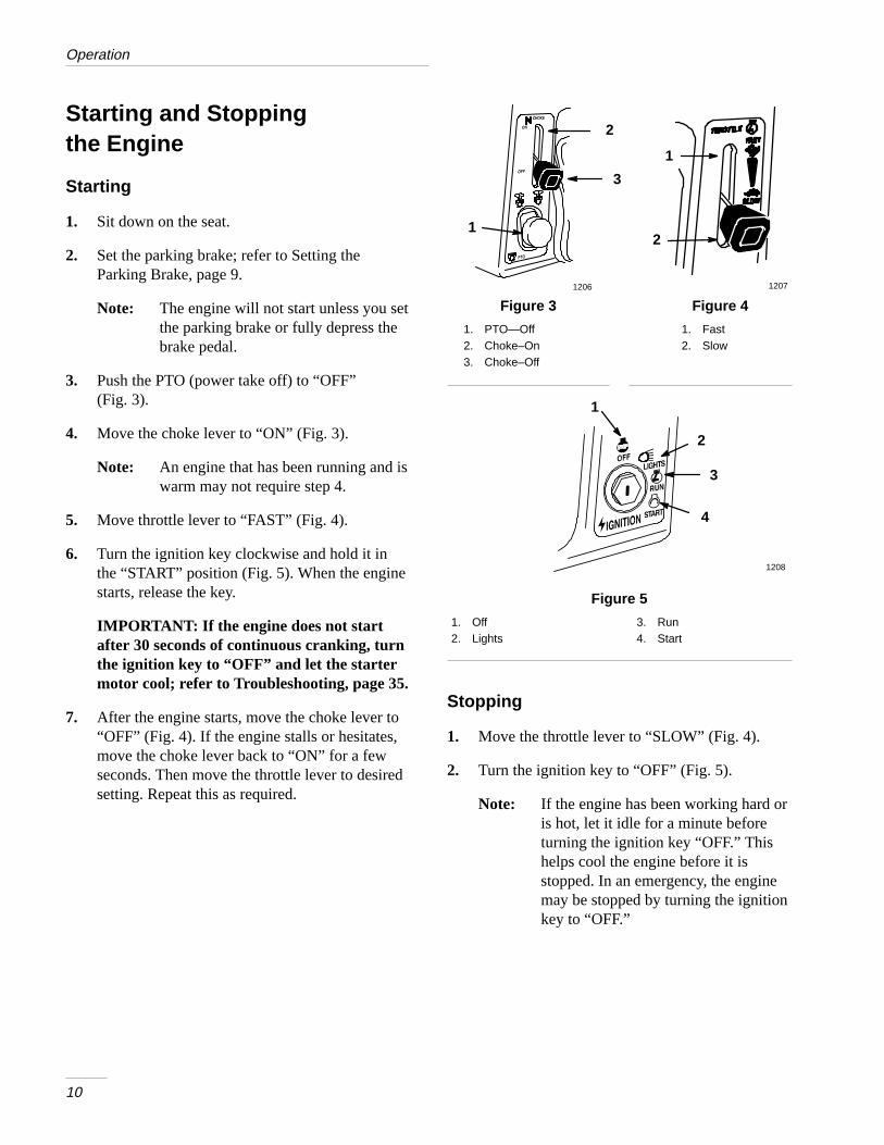
6. Turn the ignition key clockwise and hold it inthe “START” position (Fig. 5). When the enginestarts, release the key.
IMPORTANT: If the engine does not startafter 30 seconds of continuous cranking, turnthe ignition key to “OFF” and let the startermotor cool; refer to Troubleshooting, page 35.
7. After the engine starts, move the choke lever to“OFF” (Fig. 4). If the engine stalls or hesitates,move the choke lever back to “ON” for a fewseconds. Then move the throttle lever to desiredsetting. Repeat this as required.
Figure 3
1. PTO—Off2. Choke–On3. Choke–Off
Figure 4
1. Fast2. Slow
1
3
1207
1
2
1206
2
Figure 5
1. Off2. Lights
3. Run4. Start
3
2
1
1208
4
Stopping
1. Move the throttle lever to “SLOW” (Fig. 4).
2. Turn the ignition key to “OFF” (Fig. 5).
Note: If the engine has been working hard oris hot, let it idle for a minute beforeturning the ignition key “OFF.” Thishelps cool the engine before it isstopped. In an emergency, the enginemay be stopped by turning the ignitionkey to “OFF.”
Operation
11
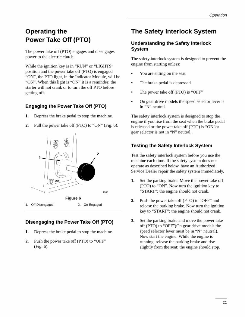
Operating thePower Take Off (PTO)
The power take off (PTO) engages and disengagespower to the electric clutch.
While the ignition key is in “RUN” or “LIGHTS”position and the power take off (PTO) is engaged“ON”, the PTO light, in the Indicator Module, will be“ON”. When this light is “ON” it is a reminder; thestarter will not crank or to turn the off PTO beforegetting off.
Engaging the Power Take Off (PTO)
1. Depress the brake pedal to stop the machine.
2. Pull the power take off (PTO) to “ON” (Fig. 6).
12
1206
Figure 6
1. Off-Disengaged 2. On-Engaged
Disengaging the Power Take Off (PTO)
1. Depress the brake pedal to stop the machine.
2. Push the power take off (PTO) to “OFF”(Fig. 6).
The Safety Interlock System
Understanding the Safety InterlockSystem
The safety interlock system is designed to prevent theengine from starting unless:
• You are sitting on the seat
• The brake pedal is depressed
• The power take off (PTO) is “OFF”
• On gear drive models the speed selector lever isin “N” neutral.
The safety interlock system is designed to stop theengine if you rise from the seat when the brake pedalis released or the power take off (PTO) is “ON”orgear selector is not in “N” neutral.
Testing the Safety Interlock System
Test the safety interlock system before you use themachine each time. If the safety system does notoperate as described below, have an AuthorizedService Dealer repair the safety system immediately.
1. Set the parking brake. Move the power take off(PTO) to “ON”. Now turn the ignition key to“START”; the engine should not crank.
2. Push the power take off (PTO) to “OFF” andrelease the parking brake. Now turn the ignitionkey to “START”; the engine should not crank.
3. Set the parking brake and move the power takeoff (PTO) to “OFF”(On gear drive models thespeed selector lever must be in “N” neutral).Now start the engine. While the engine isrunning, release the parking brake and riseslightly from the seat; the engine should stop.
Operation
12
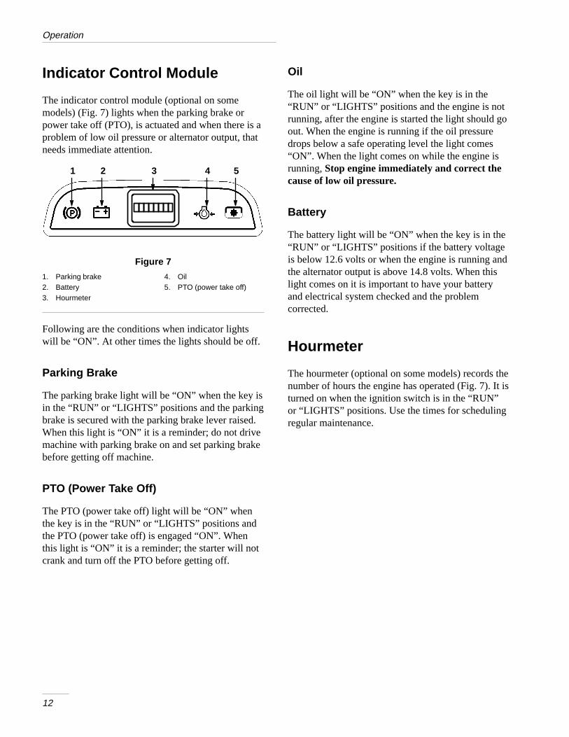
Indicator Control Module
The indicator control module (optional on somemodels) (Fig. 7) lights when the parking brake orpower take off (PTO), is actuated and when there is aproblem of low oil pressure or alternator output, thatneeds immediate attention.
5421 3
Figure 7
1. Parking brake2. Battery3. Hourmeter
4. Oil5. PTO (power take off)
Following are the conditions when indicator lightswill be “ON”. At other times the lights should be off.
Parking Brake
The parking brake light will be “ON” when the key isin the “RUN” or “LIGHTS” positions and the parkingbrake is secured with the parking brake lever raised.When this light is “ON” it is a reminder; do not drivemachine with parking brake on and set parking brakebefore getting off machine.
PTO (Power Take Off)
The PTO (power take off) light will be “ON” whenthe key is in the “RUN” or “LIGHTS” positions andthe PTO (power take off) is engaged “ON”. Whenthis light is “ON” it is a reminder; the starter will notcrank and turn off the PTO before getting off.
Oil
The oil light will be “ON” when the key is in the“RUN” or “LIGHTS” positions and the engine is notrunning, after the engine is started the light should goout. When the engine is running if the oil pressuredrops below a safe operating level the light comes“ON”. When the light comes on while the engine isrunning, Stop engine immediately and correct thecause of low oil pressure.
Battery
The battery light will be “ON” when the key is in the“RUN” or “LIGHTS” positions if the battery voltageis below 12.6 volts or when the engine is running andthe alternator output is above 14.8 volts. When thislight comes on it is important to have your batteryand electrical system checked and the problemcorrected.
Hourmeter
The hourmeter (optional on some models) records thenumber of hours the engine has operated (Fig. 7). It isturned on when the ignition switch is in the “RUN”or “LIGHTS” positions. Use the times for schedulingregular maintenance.
Operation
13
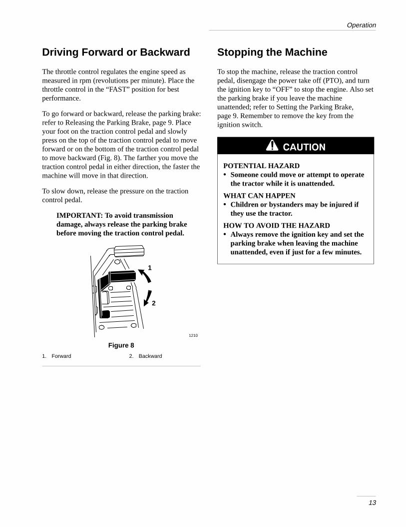
Driving Forward or Backward
The throttle control regulates the engine speed asmeasured in rpm (revolutions per minute). Place thethrottle control in the “FAST” position for bestperformance.
To go forward or backward, release the parking brake:refer to Releasing the Parking Brake, page 9. Placeyour foot on the traction control pedal and slowlypress on the top of the traction control pedal to moveforward or on the bottom of the traction control pedalto move backward (Fig. 8). The farther you move thetraction control pedal in either direction, the faster themachine will move in that direction.
To slow down, release the pressure on the tractioncontrol pedal.
IMPORTANT: To avoid transmissiondamage, always release the parking brakebefore moving the traction control pedal.
1
2
1210
Figure 8
1. Forward 2. Backward
Stopping the Machine
To stop the machine, release the traction controlpedal, disengage the power take off (PTO), and turnthe ignition key to “OFF” to stop the engine. Also setthe parking brake if you leave the machineunattended; refer to Setting the Parking Brake,page 9. Remember to remove the key from theignition switch.
POTENTIAL HAZARD• Someone could move or attempt to operate
the tractor while it is unattended.
WHAT CAN HAPPEN• Children or bystanders may be injured if
they use the tractor.
HOW TO AVOID THE HAZARD• Always remove the ignition key and set the
parking brake when leaving the machineunattended, even if just for a few minutes.

Operation
14
Attachment Lift Lever
The attachment lift lever (Fig. 9) is used to raise andlower various attachments.
Raising Attachments
1. Depress the brake pedal to stop the machine.
2. Pull attachment lift lever rearward until latchlocks. In this position the lift will hold theattachment in the up, or raised position.
Lowering Attachments
1. Depress the brake pedal to stop the machine.
2. Pull attachment lift lever rearward, to release liftpressure, and push the button on top to releasethe latch. Move lift lever forward to lowerattachment.
1205
3
2
45
6
1
Figure 9
1. Lift lever2. Button3. Dial-A-Height
4. Indicator5. High6. Mounting position
Adjusting Dial-A-Height
The Dial-A-Height control (Fig. 9) is used to limit thedownward travel of the attachment. TheDial-A-Height knob is rotated to change the locationof this stop, up or down.
1. Raise the attachment lift lever: Refer to RaisingAttachments. In the raised position theDial-A-Height knob (Fig. 9) can be rotated tochange the stop location. Turn clockwise to raiseand counterclockwise to lower the height of theattachment.
2. The Dial-A-Height indicator (Fig. 9) will showthe change, high to low, in attachment lift heightas adjustment is made.
Operation
15
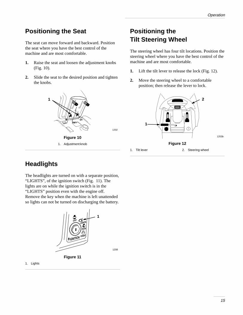
Positioning the Seat
The seat can move forward and backward. Positionthe seat where you have the best control of themachine and are most comfortable.
1. Raise the seat and loosen the adjustment knobs(Fig. 10).
2. Slide the seat to the desired position and tightenthe knobs.
1
1200
1202
Figure 10
1. Adjustment knob
Headlights
The headlights are turned on with a separate position,“LIGHTS”, of the ignition switch (Fig. 11). Thelights are on while the ignition switch is in the“LIGHTS” position even with the engine off.Remove the key when the machine is left unattendedso lights can not be turned on discharging the battery.
1208
1
Figure 11
1. Lights
Positioning theTilt Steering Wheel
The steering wheel has four tilt locations. Position thesteering wheel where you have the best control of themachine and are most comfortable.
1. Lift the tilt lever to release the lock (Fig. 12).
2. Move the steering wheel to a comfortableposition; then release the lever to lock.
1
2
1203b
Figure 12
1. Tilt lever 2. Steering wheel
Operation
16
Using the Cruise Control
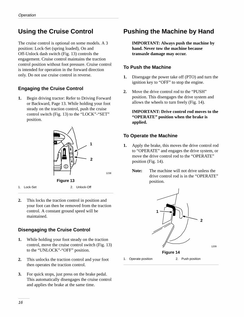
The cruise control is optional on some models. A 3position: Lock-Set (spring loaded), On andOff-Unlock dash switch (Fig. 13) controls theengagement. Cruise control maintains the tractioncontrol position without foot pressure. Cruise controlis intended for operation in the forward directiononly. Do not use cruise control in reverse.
Engaging the Cruise Control
1. Begin driving tractor: Refer to Driving Forwardor Backward, Page 13. While holding your footsteady on the traction control, push the cruisecontrol switch (Fig. 13) to the “LOCK”-“SET”position.
1
2
1238
Figure 13
1. Lock-Set 2. Unlock-Off
2. This locks the traction control in position andyour foot can then be removed from the tractioncontrol. A constant ground speed will bemaintained.
Disengaging the Cruise Control
1. While holding your foot steady on the tractioncontrol, move the cruise control switch (Fig. 13)to the “UNLOCK”-“OFF” position.
2. This unlocks the traction control and your footthen operates the traction control.
3. For quick stops, just press on the brake pedal.This automatically disengages the cruise controland applies the brake at the same time.
Pushing the Machine by Hand
IMPORTANT: Always push the machine byhand. Never tow the machine becausetransaxle damage may occur.
To Push the Machine
1. Disengage the power take off (PTO) and turn theignition key to “OFF” to stop the engine.
2. Move the drive control rod to the “PUSH”position. This disengages the drive system andallows the wheels to turn freely (Fig. 14).
IMPORTANT: Drive control rod moves to the“OPERATE” position when the brake isapplied.
To Operate the Machine
1. Apply the brake, this moves the drive control rodto “OPERATE” and engages the drive system, ormove the drive control rod to the “OPERATE”position (Fig. 14).
Note: The machine will not drive unless thedrive control rod is in the “OPERATE”position.
1
2
1209
Figure 14
1. Operate position 2. Push position
17
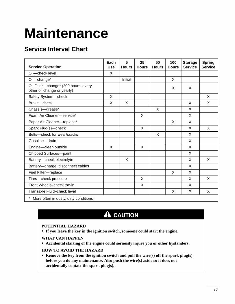
MaintenanceService Interval Chart
Service OperationEachUse
5Hours
25Hours
50Hours
100Hours
StorageService
SpringService
Oil—check level X
Oil—change* Initial X
Oil Filter—change* (200 hours, everyother oil change or yearly)
X X
Safety System—check X X
Brake—check X X X X
Chassis—grease* X X
Foam Air Cleaner—service* X X
Paper Air Cleaner—replace* X X
Spark Plug(s)—check X X X
Belts—check for wear/cracks X X
Gasoline—drain X
Engine—clean outside X X X
Chipped Surfaces—paint X
Battery—check electrolyte X X X
Battery—charge, disconnect cables X
Fuel Filter—replace X X
Tires—check pressure X X X
Front Wheels–check toe-in X X
Transaxle Fluid–check level X X X
* More often in dusty, dirty conditions
POTENTIAL HAZARD• If you leave the key in the ignition switch, someone could start the engine.
WHAT CAN HAPPEN• Accidental starting of the engine could seriously injure you or other bystanders.
HOW TO AVOID THE HAZARD• Remove the key from the ignition switch and pull the wire(s) off the spark plug(s)
before you do any maintenance. Also push the wire(s) aside so it does notaccidentally contact the spark plug(s).
Maintenance
18
Air Cleaner
Service Interval/Specification
Foam Element: Clean and re-oil after every 25operating hours, or yearly, whichever occurs first.
Paper Element: Replace after every 100 operatinghours or yearly, whichever occurs first.
Note: Service the air cleaner more frequently(every few hours) if operatingconditions are extremely dusty orsandy.
Removing the Foam and Paper Elements
1. Disengage the power take off (PTO), set theparking brake, and turn the ignition key to“OFF” to stop the engine. Remove the key.
2. Open the hood.
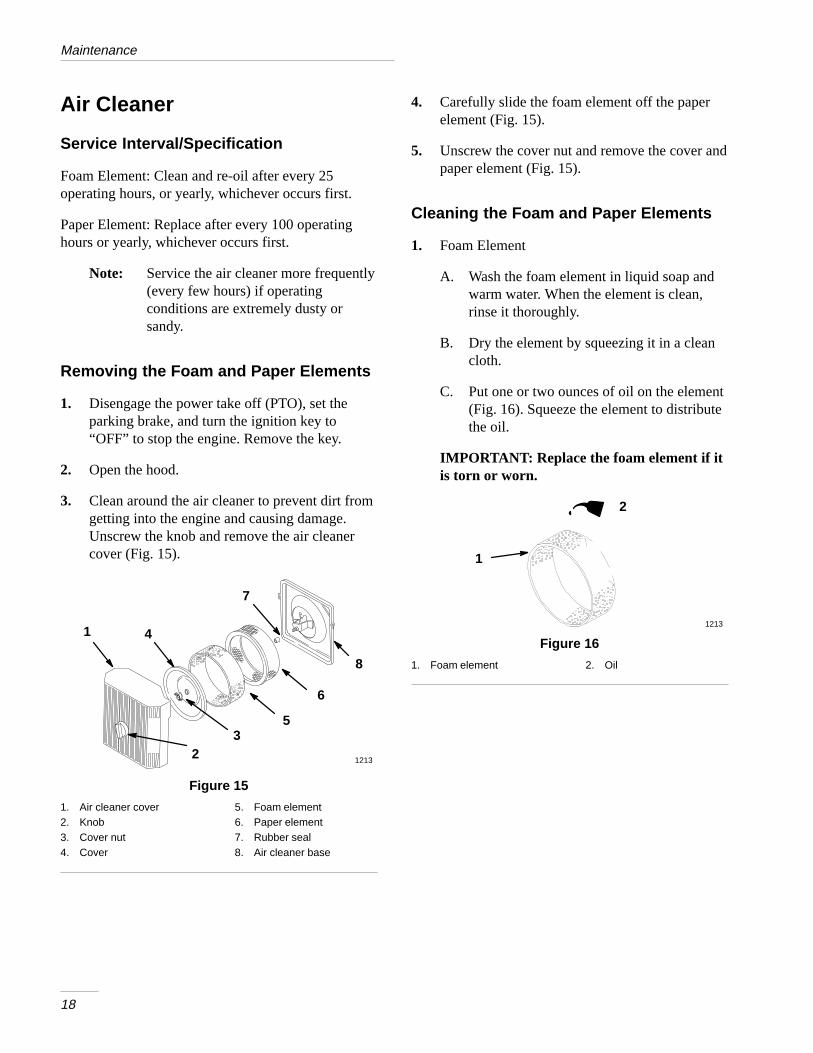
3. Clean around the air cleaner to prevent dirt fromgetting into the engine and causing damage.Unscrew the knob and remove the air cleanercover (Fig. 15).
1
2 1213
3
4
5
6
8
7
Figure 15
1. Air cleaner cover2. Knob3. Cover nut4. Cover
5. Foam element6. Paper element7. Rubber seal8. Air cleaner base
4. Carefully slide the foam element off the paperelement (Fig. 15).
5. Unscrew the cover nut and remove the cover andpaper element (Fig. 15).
Cleaning the Foam and Paper Elements
1. Foam Element
A. Wash the foam element in liquid soap andwarm water. When the element is clean,rinse it thoroughly.
B. Dry the element by squeezing it in a cleancloth.
C. Put one or two ounces of oil on the element(Fig. 16). Squeeze the element to distributethe oil.
IMPORTANT: Replace the foam element if itis torn or worn.
2
1213
1
Figure 16
1. Foam element 2. Oil
Maintenance
19
2. Paper Element
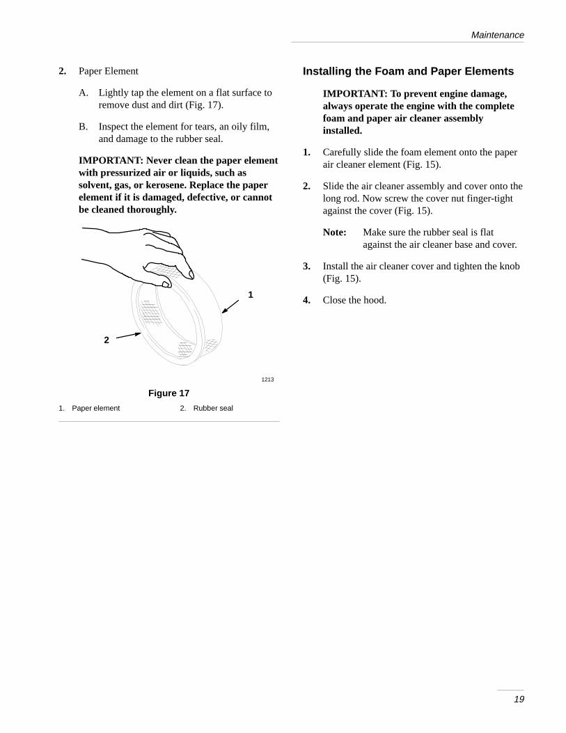
A. Lightly tap the element on a flat surface toremove dust and dirt (Fig. 17).
B. Inspect the element for tears, an oily film,and damage to the rubber seal.
IMPORTANT: Never clean the paper elementwith pressurized air or liquids, such assolvent, gas, or kerosene. Replace the paperelement if it is damaged, defective, or cannotbe cleaned thoroughly.
1
1213
2
Figure 17
1. Paper element 2. Rubber seal
Installing the Foam and Paper Elements
IMPORTANT: To prevent engine damage,always operate the engine with the completefoam and paper air cleaner assemblyinstalled.
1. Carefully slide the foam element onto the paperair cleaner element (Fig. 15).
2. Slide the air cleaner assembly and cover onto thelong rod. Now screw the cover nut finger-tightagainst the cover (Fig. 15).
Note: Make sure the rubber seal is flatagainst the air cleaner base and cover.
3. Install the air cleaner cover and tighten the knob(Fig. 15).
4. Close the hood.
Maintenance
20
Engine Oil
Service Interval/Specification
Change oil:
• After the first 5 operating hours.
• After every 100 operating hours.
Note: Change oil more frequently whenoperating conditions are extremelydusty or sandy.
Oil Type: Detergent oil (API service SF or SG)
Crankcase Capacity: w/filter, 4 pints (1.9 l)
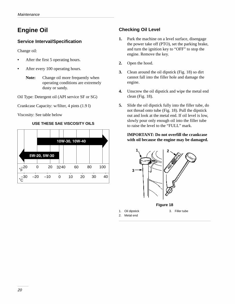
Viscosity: See table below
F–20 0 20 40 60 80 100
°
C–30
°–20 –10 0 10 20 30 40
USE THESE SAE VISCOSITY OILS
32
Checking Oil Level
1. Park the machine on a level surface, disengagethe power take off (PTO), set the parking brake,and turn the ignition key to “OFF” to stop theengine. Remove the key.
2. Open the hood.
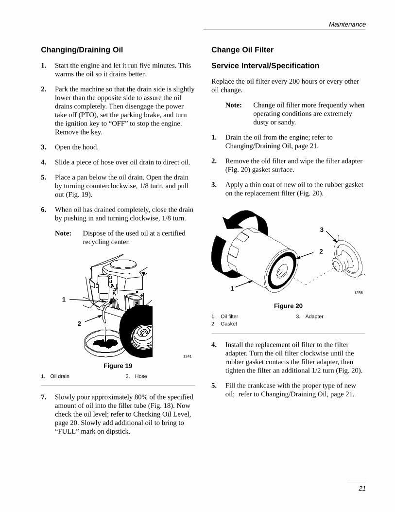
3. Clean around the oil dipstick (Fig. 18) so dirtcannot fall into the filler hole and damage theengine.
4. Unscrew the oil dipstick and wipe the metal endclean (Fig. 18).
5. Slide the oil dipstick fully into the filler tube, donot thread onto tube (Fig. 18). Pull the dipstickout and look at the metal end. If oil level is low,slowly pour only enough oil into the filler tubeto raise the level to the “FULL” mark.
IMPORTANT: Do not overfill the crankcasewith oil because the engine may be damaged.
1 2
3
Figure 18
1. Oil dipstick2. Metal end
3. Filler tube
Maintenance
21
Changing/Draining Oil
1. Start the engine and let it run five minutes. Thiswarms the oil so it drains better.
2. Park the machine so that the drain side is slightlylower than the opposite side to assure the oildrains completely. Then disengage the powertake off (PTO), set the parking brake, and turnthe ignition key to “OFF” to stop the engine.Remove the key.
3. Open the hood.
4. Slide a piece of hose over oil drain to direct oil.
5. Place a pan below the oil drain. Open the drainby turning counterclockwise, 1/8 turn. and pullout (Fig. 19).
6. When oil has drained completely, close the drainby pushing in and turning clockwise, 1/8 turn.
Note: Dispose of the used oil at a certifiedrecycling center.
1
2
1241
Figure 19
1. Oil drain 2. Hose
7. Slowly pour approximately 80% of the specifiedamount of oil into the filler tube (Fig. 18). Nowcheck the oil level; refer to Checking Oil Level,page 20. Slowly add additional oil to bring to“FULL” mark on dipstick.
Change Oil Filter
Service Interval/Specification
Replace the oil filter every 200 hours or every otheroil change.
Note: Change oil filter more frequently whenoperating conditions are extremelydusty or sandy.
1. Drain the oil from the engine; refer toChanging/Draining Oil, page 21.
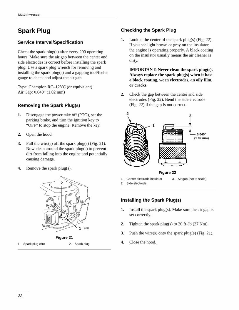
2. Remove the old filter and wipe the filter adapter(Fig. 20) gasket surface.
3. Apply a thin coat of new oil to the rubber gasketon the replacement filter (Fig. 20).
12561
2
3
Figure 20
1. Oil filter2. Gasket
3. Adapter
4. Install the replacement oil filter to the filteradapter. Turn the oil filter clockwise until therubber gasket contacts the filter adapter, thentighten the filter an additional 1/2 turn (Fig. 20).
5. Fill the crankcase with the proper type of newoil; refer to Changing/Draining Oil, page 21.
Maintenance
22
Spark Plug
Service Interval/Specification
Check the spark plug(s) after every 200 operatinghours. Make sure the air gap between the center andside electrodes is correct before installing the sparkplug. Use a spark plug wrench for removing andinstalling the spark plug(s) and a gapping tool/feelergauge to check and adjust the air gap.
Type: Champion RC–12YC (or equivalent)Air Gap: 0.040” (1.02 mm)
Removing the Spark Plug (s)
1. Disengage the power take off (PTO), set theparking brake, and turn the ignition key to“OFF” to stop the engine. Remove the key.
2. Open the hood.
3. Pull the wire(s) off the spark plug(s) (Fig. 21).Now clean around the spark plug(s) to preventdirt from falling into the engine and potentiallycausing damage.
4. Remove the spark plug(s).
2
1 1215
Figure 21
1. Spark plug wire 2. Spark plug
Checking the Spark Plug
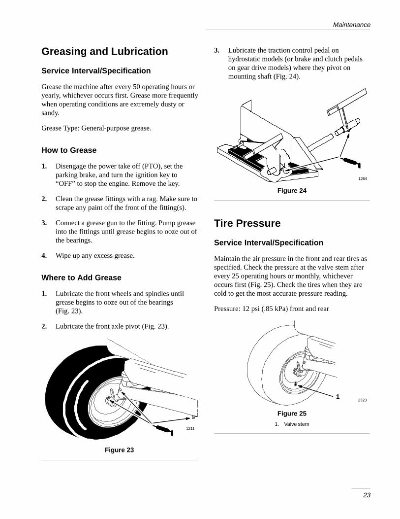
1. Look at the center of the spark plug(s) (Fig. 22).If you see light brown or gray on the insulator,the engine is operating properly. A black coatingon the insulator usually means the air cleaner isdirty.
IMPORTANT: Never clean the spark plug(s).Always replace the spark plug(s) when it has:a black coating, worn electrodes, an oily film,or cracks.
2. Check the gap between the center and sideelectrodes (Fig. 22). Bend the side electrode(Fig. 22) if the gap is not correct.
0.040”(1.02 mm)
2 3
1
Figure 22
1. Center electrode insulator2. Side electrode
3. Air gap (not to scale)
Installing the Spark Plug (s)
1. Install the spark plug(s). Make sure the air gap isset correctly.
2. Tighten the spark plug(s) to 20 ft–lb (27 Nm).
3. Push the wire(s) onto the spark plug(s) (Fig. 21).
4. Close the hood.
Maintenance
23
Greasing and Lubrication
Service Interval/Specification
Grease the machine after every 50 operating hours oryearly, whichever occurs first. Grease more frequentlywhen operating conditions are extremely dusty orsandy.
Grease Type: General-purpose grease.
How to Grease
1. Disengage the power take off (PTO), set theparking brake, and turn the ignition key to“OFF” to stop the engine. Remove the key.
2. Clean the grease fittings with a rag. Make sure toscrape any paint off the front of the fitting(s).
3. Connect a grease gun to the fitting. Pump greaseinto the fittings until grease begins to ooze out ofthe bearings.
4. Wipe up any excess grease.
Where to Add Grease
1. Lubricate the front wheels and spindles untilgrease begins to ooze out of the bearings (Fig. 23).
2. Lubricate the front axle pivot (Fig. 23).
1211
Figure 23
3. Lubricate the traction control pedal onhydrostatic models (or brake and clutch pedalson gear drive models) where they pivot onmounting shaft (Fig. 24).
1264
Figure 24
Tire Pressure
Service Interval/Specification
Maintain the air pressure in the front and rear tires asspecified. Check the pressure at the valve stem afterevery 25 operating hours or monthly, whicheveroccurs first (Fig. 25). Check the tires when they arecold to get the most accurate pressure reading.
Pressure: 12 psi (.85 kPa) front and rear
12323
Figure 25
1. Valve stem
Maintenance
24
Brake
Always set the parking brake when you stop themachine or leave it unattended. If the parking brakedoes not hold securely, an adjustment is required.
Checking the Brake
1. Park the machine on a level surface, disengagethe power take off (PTO), set the parking brake,and turn the ignition key to “OFF” to stop theengine. Remove the key.
2. Rear wheels must lock and skid when you try topush the tractor forward. Adjustment is requiredif the wheels turn and do not lock; refer toAdjusting the Brake, page 24.
3. Move the drive control rod to the “PUSH”position; refer to Pushing the Machine by Hand,page 16. Wheels should rotate freely.
4. If both conditions are met no adjustment isrequired.
IMPORTANT: Drive control rod moves to the“OPERATE” position when the brake isapplied.
Adjusting the Brake
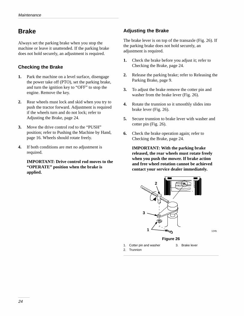
The brake lever is on top of the transaxle (Fig. 26). Ifthe parking brake does not hold securely, anadjustment is required.
1. Check the brake before you adjust it; refer toChecking the Brake, page 24.
2. Release the parking brake; refer to Releasing theParking Brake, page 9.
3. To adjust the brake remove the cotter pin andwasher from the brake lever (Fig. 26).
4. Rotate the trunnion so it smoothly slides intobrake lever (Fig. 26).
5. Secure trunnion to brake lever with washer andcotter pin (Fig. 26).
6. Check the brake operation again; refer toChecking the Brake, page 24.
IMPORTANT: With the parking brakereleased, the rear wheels must rotate freelywhen you push the mower. If brake actionand free wheel rotation cannot be achievedcontact your service dealer immediately.
1
2
3
1245
Figure 26
1. Cotter pin and washer2. Trunnion
3. Brake lever
Maintenance
25
Fuel Tank
Draining The Fuel Tank
POTENTIAL HAZARD• In certain conditions gasoline is extremely
flammable and highly explosive.
WHAT CAN HAPPEN• A fire or explosion from gasoline can burn
you, others, and cause property damage.
HOW TO AVOID THE HAZARD• Drain gasoline from the fuel tank when the
engine is cold. Do this outdoors in an openarea. Wipe up any gasoline that spills.
• Never drain gasoline near an open flame orwhere gasoline fumes may be ignited by aspark.
• Never smoke a cigarette, cigar or pipe.
1. Park the machine on a level surface, to assurefuel tank drains completely. Then disengage thepower take off (PTO), set the parking brake, andturn the ignition key to “OFF” to stop theengine. Remove the key.
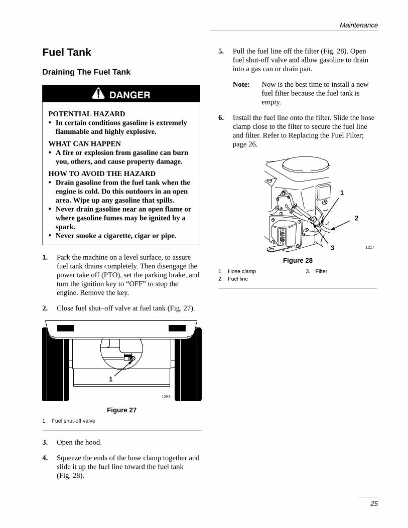
2. Close fuel shut–off valve at fuel tank (Fig. 27).
1263
1
Figure 27
1. Fuel shut-off valve
3. Open the hood.
4. Squeeze the ends of the hose clamp together andslide it up the fuel line toward the fuel tank(Fig. 28).
5. Pull the fuel line off the filter (Fig. 28). Openfuel shut-off valve and allow gasoline to draininto a gas can or drain pan.
Note: Now is the best time to install a newfuel filter because the fuel tank isempty.
6. Install the fuel line onto the filter. Slide the hoseclamp close to the filter to secure the fuel lineand filter. Refer to Replacing the Fuel Filter;page 26.
1
2
3 1217
Figure 28
1. Hose clamp2. Fuel line
3. Filter
Maintenance
26
Fuel Filter
Service Interval/Specification
Replace the fuel filter after every 100 operating hoursor yearly, whichever occurs first.
Replacing the Fuel Filter
Never install a dirty filter if it is removed from thefuel line.
1. Disengage the power take off (PTO), set theparking brake, and turn the ignition key to“OFF” to stop the engine. Remove the key.
2. Close fuel shut–off valve at fuel tank (Fig. 27).
3. Open the hood.
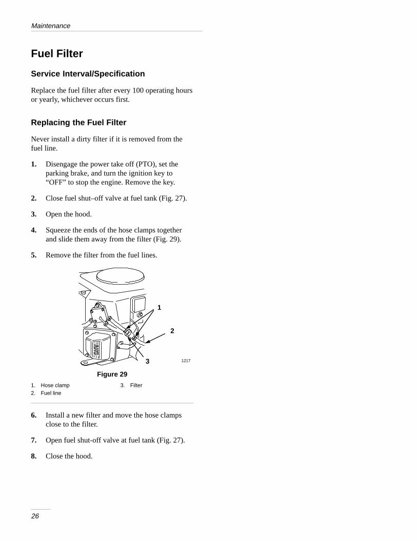
4. Squeeze the ends of the hose clamps togetherand slide them away from the filter (Fig. 29).
5. Remove the filter from the fuel lines.
1
2
3 1217
Figure 29
1. Hose clamp2. Fuel line
3. Filter
6. Install a new filter and move the hose clampsclose to the filter.
7. Open fuel shut-off valve at fuel tank (Fig. 27).
8. Close the hood.
Maintenance
27
Front Wheel Toe-In
Service Interval/Specification
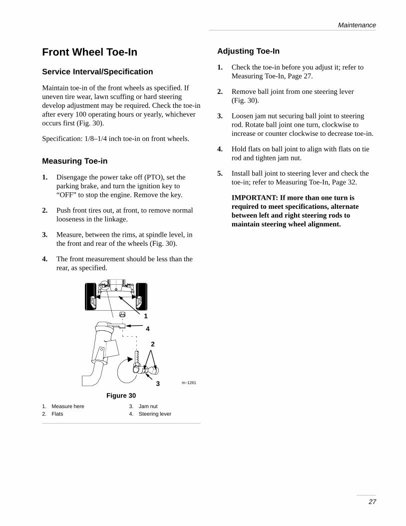
Maintain toe-in of the front wheels as specified. Ifuneven tire wear, lawn scuffing or hard steeringdevelop adjustment may be required. Check the toe-inafter every 100 operating hours or yearly, whicheveroccurs first (Fig. 30).
Specification: 1/8–1/4 inch toe-in on front wheels.
Measuring Toe-in
1. Disengage the power take off (PTO), set theparking brake, and turn the ignition key to“OFF” to stop the engine. Remove the key.
2. Push front tires out, at front, to remove normallooseness in the linkage.
3. Measure, between the rims, at spindle level, inthe front and rear of the wheels (Fig. 30).
4. The front measurement should be less than therear, as specified.
1
4
3
2
m–1261
Figure 30
1. Measure here2. Flats
3. Jam nut4. Steering lever
Adjusting Toe-In
1. Check the toe-in before you adjust it; refer toMeasuring Toe-In, Page 27.
2. Remove ball joint from one steering lever(Fig. 30).
3. Loosen jam nut securing ball joint to steeringrod. Rotate ball joint one turn, clockwise toincrease or counter clockwise to decrease toe-in.
4. Hold flats on ball joint to align with flats on tierod and tighten jam nut.
5. Install ball joint to steering lever and check thetoe-in; refer to Measuring Toe-In, Page 32.
IMPORTANT: If more than one turn isrequired to meet specifications, alternatebetween left and right steering rods tomaintain steering wheel alignment.
Maintenance
28
Transaxle Fluid
Service Interval/Specification
Check fluid level after every 100 hours or yearlywhichever comes first. Always keep the fluid level atthe full level when the transaxle is cold. The transaxleis a sealed system and no changing of the fluid isrequired.
Fluid Type: SAE 10W–30 Detergent oil (API serviceSF or SG)
Checking Fluid Level
1. Park the machine on a level surface, disengagethe power take off (PTO), set the parking brake,and turn the ignition key to “OFF” to stop theengine. Remove the key.
2. Open the hood.
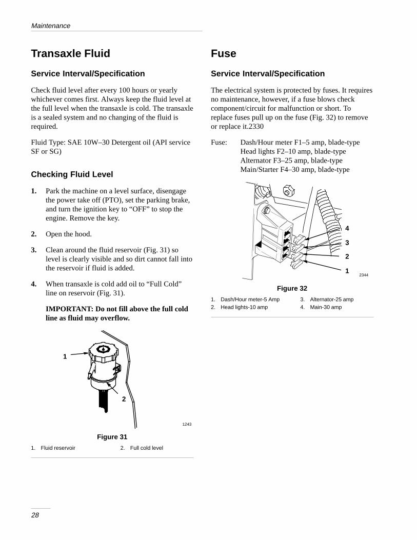
3. Clean around the fluid reservoir (Fig. 31) solevel is clearly visible and so dirt cannot fall intothe reservoir if fluid is added.
4. When transaxle is cold add oil to “Full Cold”line on reservoir (Fig. 31).
IMPORTANT: Do not fill above the full coldline as fluid may overflow.
1243
2
1
Figure 31
1. Fluid reservoir 2. Full cold level
Fuse
Service Interval/Specification
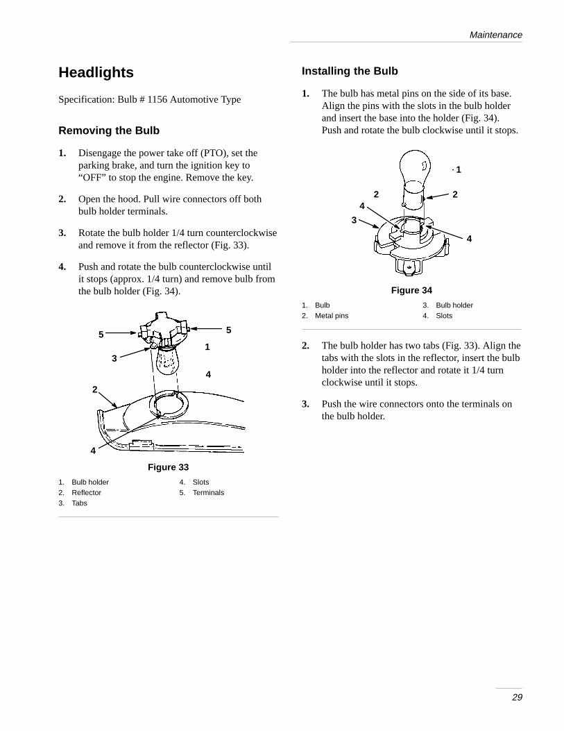
The electrical system is protected by fuses. It requiresno maintenance, however, if a fuse blows checkcomponent/circuit for malfunction or short. Toreplace fuses pull up on the fuse (Fig. 32) to removeor replace it.2330
Fuse: Dash/Hour meter F1–5 amp, blade-typeHead lights F2–10 amp, blade-typeAlternator F3–25 amp, blade-typeMain/Starter F4–30 amp, blade-type
23441
2
3
4
Figure 32
1. Dash/Hour meter-5 Amp2. Head lights-10 amp
3. Alternator-25 amp4. Main-30 amp
Maintenance
29
Headlights
Specification: Bulb # 1156 Automotive Type
Removing the Bulb
1. Disengage the power take off (PTO), set theparking brake, and turn the ignition key to“OFF” to stop the engine. Remove the key.
2. Open the hood. Pull wire connectors off bothbulb holder terminals.
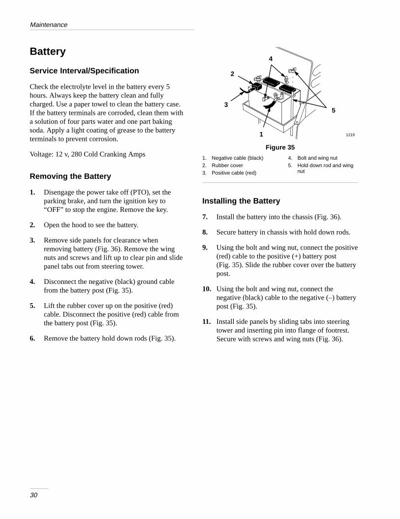
3. Rotate the bulb holder 1/4 turn counterclockwiseand remove it from the reflector (Fig. 33).
4. Push and rotate the bulb counterclockwise untilit stops (approx. 1/4 turn) and remove bulb fromthe bulb holder (Fig. 34).
1
2
3
4
4
5 5
Figure 33
1. Bulb holder2. Reflector3. Tabs
4. Slots5. Terminals
Installing the Bulb
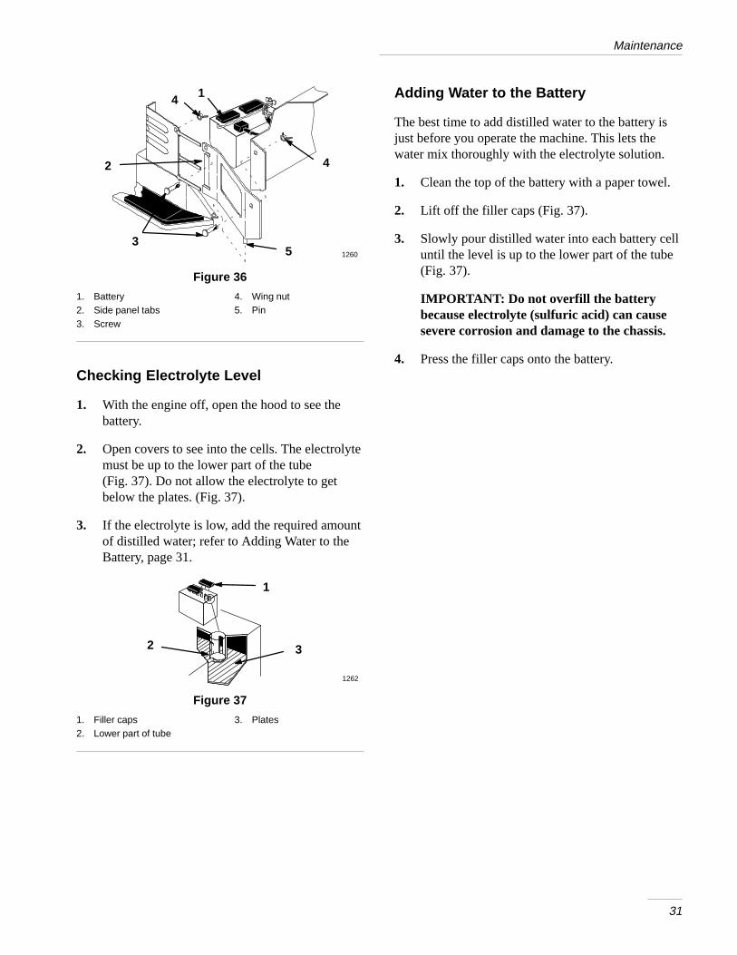
1. The bulb has metal pins on the side of its base.Align the pins with the slots in the bulb holderand insert the base into the holder (Fig. 34).Push and rotate the bulb clockwise until it stops.
1
2
3
42
4
Figure 34
1. Bulb2. Metal pins
3. Bulb holder4. Slots
2. The bulb holder has two tabs (Fig. 33). Align thetabs with the slots in the reflector, insert the bulbholder into the reflector and rotate it 1/4 turnclockwise until it stops.
3. Push the wire connectors onto the terminals onthe bulb holder.
Maintenance
30
Battery
Service Interval/Specification
Check the electrolyte level in the battery every 5hours. Always keep the battery clean and fullycharged. Use a paper towel to clean the battery case.If the battery terminals are corroded, clean them witha solution of four parts water and one part bakingsoda. Apply a light coating of grease to the batteryterminals to prevent corrosion.
Voltage: 12 v, 280 Cold Cranking Amps
Removing the Battery
1. Disengage the power take off (PTO), set theparking brake, and turn the ignition key to“OFF” to stop the engine. Remove the key.
2. Open the hood to see the battery.
3. Remove side panels for clearance whenremoving battery (Fig. 36). Remove the wingnuts and screws and lift up to clear pin and slidepanel tabs out from steering tower.
4. Disconnect the negative (black) ground cablefrom the battery post (Fig. 35).
5. Lift the rubber cover up on the positive (red)cable. Disconnect the positive (red) cable fromthe battery post (Fig. 35).
6. Remove the battery hold down rods (Fig. 35).
1
2
35
4
1219
Figure 35
1. Negative cable (black)2. Rubber cover3. Positive cable (red)
4. Bolt and wing nut5. Hold down rod and wing
nut
Installing the Battery
7. Install the battery into the chassis (Fig. 36).
8. Secure battery in chassis with hold down rods.
9. Using the bolt and wing nut, connect the positive(red) cable to the positive (+) battery post(Fig. 35). Slide the rubber cover over the batterypost.
10. Using the bolt and wing nut, connect thenegative (black) cable to the negative (–) batterypost (Fig. 35).
11. Install side panels by sliding tabs into steeringtower and inserting pin into flange of footrest.Secure with screws and wing nuts (Fig. 36).
Maintenance
31
1
2
3
4
5 1260
4
Figure 36
1. Battery2. Side panel tabs3. Screw
4. Wing nut5. Pin
Checking Electrolyte Level
1. With the engine off, open the hood to see thebattery.
2. Open covers to see into the cells. The electrolytemust be up to the lower part of the tube (Fig. 37). Do not allow the electrolyte to getbelow the plates. (Fig. 37).
3. If the electrolyte is low, add the required amountof distilled water; refer to Adding Water to theBattery, page 31.
1
2 3
1262
Figure 37
1. Filler caps2. Lower part of tube
3. Plates
Adding Water to the Battery
The best time to add distilled water to the battery isjust before you operate the machine. This lets thewater mix thoroughly with the electrolyte solution.
1. Clean the top of the battery with a paper towel.
2. Lift off the filler caps (Fig. 37).
3. Slowly pour distilled water into each battery celluntil the level is up to the lower part of the tube(Fig. 37).
IMPORTANT: Do not overfill the batterybecause electrolyte (sulfuric acid) can causesevere corrosion and damage to the chassis.
4. Press the filler caps onto the battery.
Maintenance
32
Charging the Battery
IMPORTANT: Always keep the battery fullycharged (1.260 specific gravity). This isespecially important to prevent batterydamage when the temperature is below 32°F(0°C).
1. Remove the battery from the chassis; refer toRemoving the Battery, page 30.
2. Check the electrolyte level; refer to CheckingElectrolyte Level, page 31, steps 2–3.
3. Remove the filler caps from the battery andconnect a 3 to 4 amp battery charger to thebattery posts. Charge the battery at a rate of 4amperes or less for 4 hours (12 volts). Do notovercharge the battery. Install the filler caps afterthe battery is fully charged.
POTENTIAL HAZARD• Charging the battery produces gasses.
WHAT CAN HAPPEN• Battery gasses can explode.
HOW TO AVOID THE HAZARD• Keep cigarettes, sparks and flames away
from battery.
4. Install the battery in the chassis; refer toInstalling the Battery, page 30.
Maintenance
33
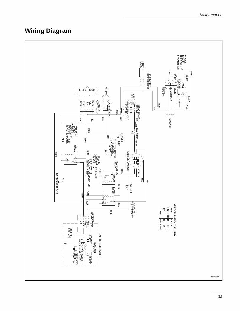
Wiring Diagram
��
��
��
��
�
��
�
��
��
�
��
��
��
��
�
���
����
����
��
��
�
��
��
�����
��
�
��
��
�
���
��
��
���
���
�
���
�
��
�
�
��
���
���
�
��
���
�������������
��
��
��
��
�
���
����
���
���
�
��
���
�
��
��
���
���
��
�
�
���
��
��
��
�
���
��
��
��
���
���
���
���
���
��
�
��
�
��
�
����
��
��
�
��
�
��
�
��
�
��
�
��
�
����
��
��
�
��
�
��
�
�
��
�
��
�
�
��
�
��
�
���
��
����
��
���
���
��
����
��
��
����
����
��
���
���
��
�
��
��
�
��
��
��
���
�
��
����
���
�
��
��
���
��
��
��
���
�
��
��
���
��
���
��
���
����
��
��
���
��
���
��
���
��
����
�����
���
��
��
��
���
��
��
��
���
���
��
���
���
���
��
��
�
��
���
��
���
���
��
�
���
��
�
��
�
��
�
���
��
���
���
���
��
�
���
��
��
����
���
���
��
��
��
��
���
��
���
��
��
���
��
���
����
���
���
�
� ��
�
���
�
��
�
��
��
��
��
�
��
�
��
��
��
��
��
��
����
��
�
��
�
��
��
�
���
���
��
��
��
��
��
�
��
�
��
�
��
�
�
���
��
��
���
��
�
��
�
���
���
��
��
���
��
���
���
��
���
�
��
��
��
������� �
��
���
�
��
�
��
��
�
��
��
�
��
���
�����
��
���
��
���
��
��
����
���
��
��
���
��
��
��
��
��
��
��
��
��
��
���
��
���
�
��
�
���
���
��
��
�
��
�
���
��
��
�
��
��
�
��
��
��
��
��
��
��
�
��
��
��
��
m–2463
Maintenance
34
Cleaning and Storage
1. Disengage the power take off (PTO), set theparking brake, and turn the ignition key to“OFF” to stop the engine. Remove the key.
2. Remove grass clippings, dirt, and grime from theexternal parts of the entire machine, especiallythe engine. Clean dirt and chaff from the outsideof the engine’s cylinder head fins and blowerhousing.
IMPORTANT: You can wash the machinewith mild detergent and water. Do notpressure wash the machine. Avoid excessiveuse of water, especially near the control panel,lights, engine, and the battery.
3. Check the brake; refer to Brake, page 23.
4. Service the air cleaner; refer to Air Cleaner,page 18.
5. Grease the chassis; refer to Greasing andLubrication, page 23.
6. Change the crankcase oil; refer to Engine Oil,page 20.
7. Remove the spark plug(s) and check itscondition; refer to Spark Plug, page 22. With thespark plug(s) removed from the engine, pour twotablespoons of engine oil into the spark plughole. Now use the electric starter to crank theengine and distribute the oil inside the cylinder.Install the spark plug(s) and tighten it to 15 ft–lb(20.4 Nm). Do not install the wire on the sparkplug(s).
8. Remove the battery from the chassis, check theelectrolyte level, and charge it fully; refer toBattery, page 30. Do not connect the batterycables to the battery posts during storage.
IMPORTANT: The battery must be fullycharged to prevent it from freezing and beingdamaged at temperatures below 32°F (0°C). Afully charged battery maintains its charge forabout 50 days at temperatures lower than
40°F (4°C). If the temperatures will be above40°F (4°C), check the water level in thebattery and charge it every 30 days.
9. Check the tire pressure; refer to Tire Pressure,page 23.
10. For long-term storage (more than 90 days) addstabilizer/conditioner additive to fuel in the tank(1 oz. per gallon).
A. Run engine to distribute conditioned fuelthrough the fuel system (5 minutes).
B. Stop engine, allow to cool and drain thefuel tank; refer to Fuel Tank, page 25, oroperate engine until it stops.
C. Restart engine and run until it stops.Repeat, on “CHOKE” until engine will notrestart.
D. Dispose of fuel properly. Recycle as perlocal codes.
Note: Do not store stabilizer/conditionedgasoline over 90 days.
11. Check and tighten all bolts, nuts, and screws.Repair or replace any part that is damaged ordefective.
12. Paint all scratched or bare metal surfaces. Paintis available from your Authorized ServiceDealer.
13. Store the machine in a clean, dry garage orstorage area. Remove the key from the ignitionswitch and keep it in a memorable place. Coverthe machine to protect it and keep it clean.
35
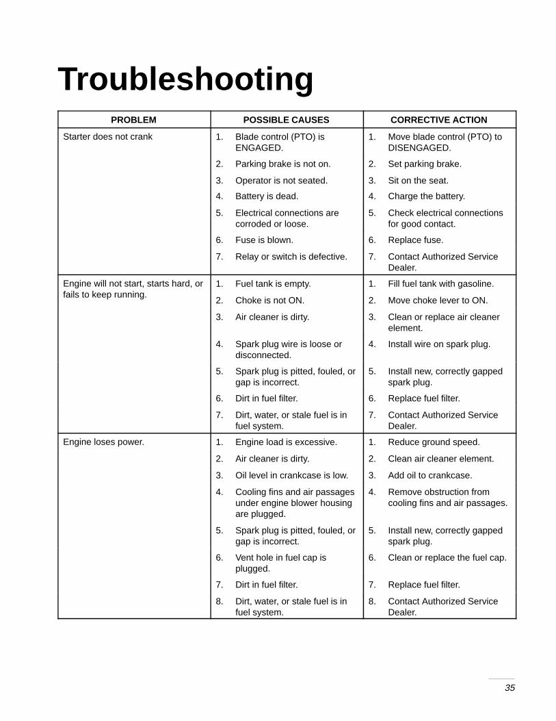
TroubleshootingPROBLEM POSSIBLE CAUSES CORRECTIVE ACTION
Starter does not crank 1. Blade control (PTO) isENGAGED.
1. Move blade control (PTO) toDISENGAGED.
2. Parking brake is not on. 2. Set parking brake.
3. Operator is not seated.
4. Battery is dead.
3. Sit on the seat.
4. Charge the battery.
5. Electrical connections arecorroded or loose.
5. Check electrical connectionsfor good contact.
6. Fuse is blown. 6. Replace fuse.
7. Relay or switch is defective. 7. Contact Authorized ServiceDealer.
Engine will not start, starts hard, orf il t k i
1. Fuel tank is empty. 1. Fill fuel tank with gasoline.fails to keep running.
2. Choke is not ON. 2. Move choke lever to ON.
3. Air cleaner is dirty. 3. Clean or replace air cleanerelement.
4. Spark plug wire is loose ordisconnected.
4. Install wire on spark plug.
5. Spark plug is pitted, fouled, orgap is incorrect.
5. Install new, correctly gappedspark plug.
6. Dirt in fuel filter. 6. Replace fuel filter.
7. Dirt, water, or stale fuel is infuel system.
7. Contact Authorized ServiceDealer.
Engine loses power. 1. Engine load is excessive. 1. Reduce ground speed.
2. Air cleaner is dirty. 2. Clean air cleaner element.
3. Oil level in crankcase is low. 3. Add oil to crankcase.
4. Cooling fins and air passagesunder engine blower housingare plugged.
4. Remove obstruction fromcooling fins and air passages.
5. Spark plug is pitted, fouled, orgap is incorrect.
5. Install new, correctly gappedspark plug.
6. Vent hole in fuel cap isplugged.
6. Clean or replace the fuel cap.
7. Dirt in fuel filter. 7. Replace fuel filter.
8. Dirt, water, or stale fuel is infuel system.
8. Contact Authorized ServiceDealer.
Troubleshooting
36
PROBLEM CORRECTIVE ACTIONPOSSIBLE CAUSES
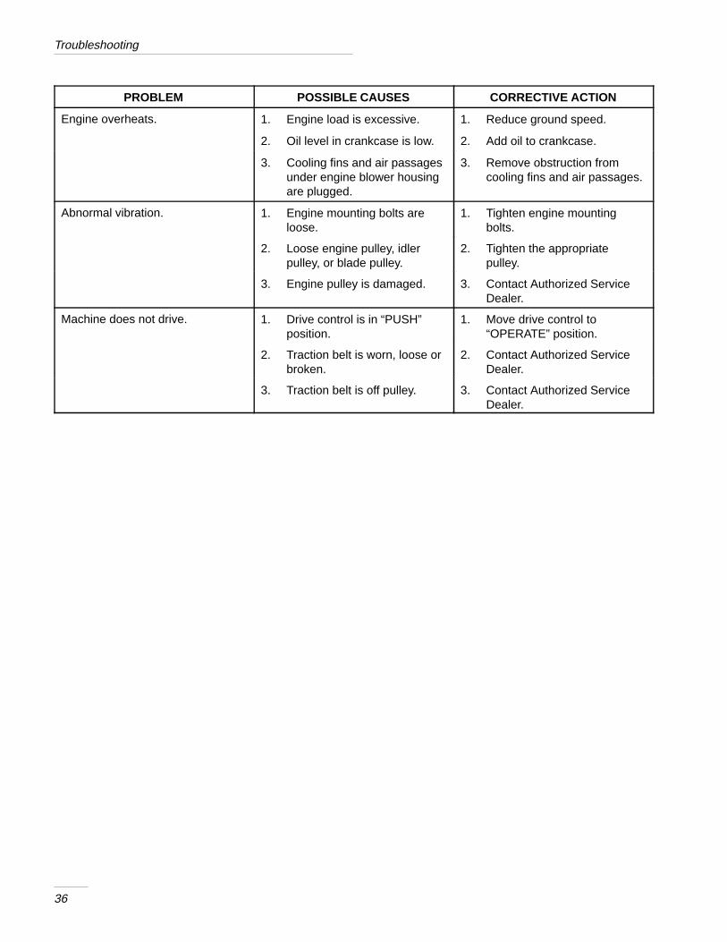
Engine overheats. 1. Engine load is excessive. 1. Reduce ground speed.
2. Oil level in crankcase is low. 2. Add oil to crankcase.
3. Cooling fins and air passagesunder engine blower housingare plugged.
3. Remove obstruction fromcooling fins and air passages.
Abnormal vibration. 1. Engine mounting bolts areloose.
1. Tighten engine mountingbolts.
2. Loose engine pulley, idlerpulley, or blade pulley.
2. Tighten the appropriatepulley.
3. Engine pulley is damaged. 3. Contact Authorized ServiceDealer.
Machine does not drive. 1. Drive control is in “PUSH”position.
1. Move drive control to“OPERATE” position.
2. Traction belt is worn, loose orbroken.
2. Contact Authorized ServiceDealer.
3. Traction belt is off pulley. 3. Contact Authorized ServiceDealer.

Rev. 7/21/97
�!�+� �*� �&-�)��� �0� �!"*� /')�**� ��))�%+0�
"-*� "474� �425&3>� 5742.8*8� 94� 7*5&.7� &3>� "� �� �74):(9
:8*)� +47� 3472&1� 7*8.)*39.&1� 5:7548*8�� .+� )*+*(9.;*� .3� 2&9*7.&18
47� <4702&38-.5� +47� &� 5*7.4)� 4+� 9<4� >*&78� +742� 9-*� )&9*� 4+
5:7(-&8*� <.9-� 9-*� +4114<.3,� *=(*59.438�
� �&99*7.*8� &7*� <&77&39*)� +47� 43*� >*&7
"-.8� <&77&39>� (4;*78� 9-*� (489� 4+� 5&798� &3)� 1&'47� &8� <*11� &8
97&385479&9.43� <.9-.3� &� �� 2.1*� 7&).:8� 4+� 9-*� 8*7;.(.3,� )*&1*7�
�!�+� �)&�,�+*� �)�� �&-�)��� �0� �!"*� ��))�%+0�
"-.8� <&77&39>� &551.*8� 94� &11� (438:2*7� 7.).3,� 574):(98� &3)
9-*.7� &99&(-2*398�
�&.� ��&,+� �&$$�)�"�#� �*��
"� �� �438:2*7� �74):(98� &3)� &99&(-2*398� :8*)� +47
(422*7(.&1�� .389.9:9.43&1� 47� 7*39&1� :8*� &7*� (4;*7*)� '>� &� 1.2.9*)
<&77&39>� +47� 9-*� +4114<.3,� 9.2*� 5*7.4)8� +742� 9-*� )&9*� 4+
5:7(-&8*�
�74):(98 $&77&39>� �*7.4)
� �� &3)� �=.� !*7.*8� "7&(9478
�-&88.8 � >*&7� 1.2.9*)� <&77&39>�� �� �� �� �� �� �� �� �� �� �� �� �� �� �� �� �� ��
�.6:.)� �441*)� �&8� �3,.3*8 � >*&7� 1.2.9*)� <&77&39>��
�.7� �441*)� �&8� &3)� �.*8*1
�3,.3*8 �� >*&7� 1.2.9*)� <&77&39>�� �� �� �� �� �� �� �� �� �� �� �� �� �� �� �� ��
� �11� �9-*78 �� )&>� 1.2.9*)� <&77&39>�� �� �� �� �� �� �� �� �� �� �� �� �� �� �� �� �� �� �� �� ��
�&.� �&� �&,� �+� ��))�%+0� ��)-"���
!-4:1)� >4:� +**1� >4:7� "� �� �74):(9� (439&.38� &� )*+*(9� .3� 2&@
9*7.&1� 47� <4702&38-.5�� (439&(9� 9-*� )*&1*7� <-4� 841)� >4:� 9-*
574):(9� 47� &3>� �:9-47.?*)� "� �� !*7;.(*� �*&1*7� 47� "� �
�&89*7� !*7;.(*� �*&1*7�� "-*� %*114<� �&,*8� 4+� >4:7� 9*1*5-43*
).7*(947>� .8� &� ,44)� 7*+*7*3(*� 84:7(*�� "-*� )*&1*7� <.11� *.9-*7
&77&3,*� 8*7;.(*� &9� -.8�-*7� )*&1*78-.5� 47� 7*(422*3)� &349-*7
�:9-47.?*)� !*7;.(*� �*&1*7� <-4� 2&>� '*� 247*� (43;*3.*39�� %4:
2&>� 3**)� 5744+� 4+� 5:7(-&8*� �(45>� 4+� 7*,.897&9.43� (&7)�� 8&1*8
7*(*.59�� *9(��� +47� <&77&39>� ;&1.)&9.43�
�+� +47� &3>� 7*&843� >4:� &7*� ).88&9.8+.*)� <.9-� 9-*� !*7;.(*� �*&1*7�8
&3&1>8.8� 4+� 9-*� )*+*(9� .3� 2&9*7.&18� 47� <4702&38-.5� 47� .+� >4:
3**)� &� 7*+*77&1� 94� &� "� �� !*7;.(*� �*&1*7�� 51*&8*� +**1� +7**� 94
(439&(9� :8� &9� 9-*� +4114<.3,� &))7*88�
"474� �:8942*7� !*7;.(*� �*5&792*39
�� �>3)&1*� �;*3:*� !4:9-
�1442.3,943�� ��� � �� �@��
��@���@��
�@� �@� �
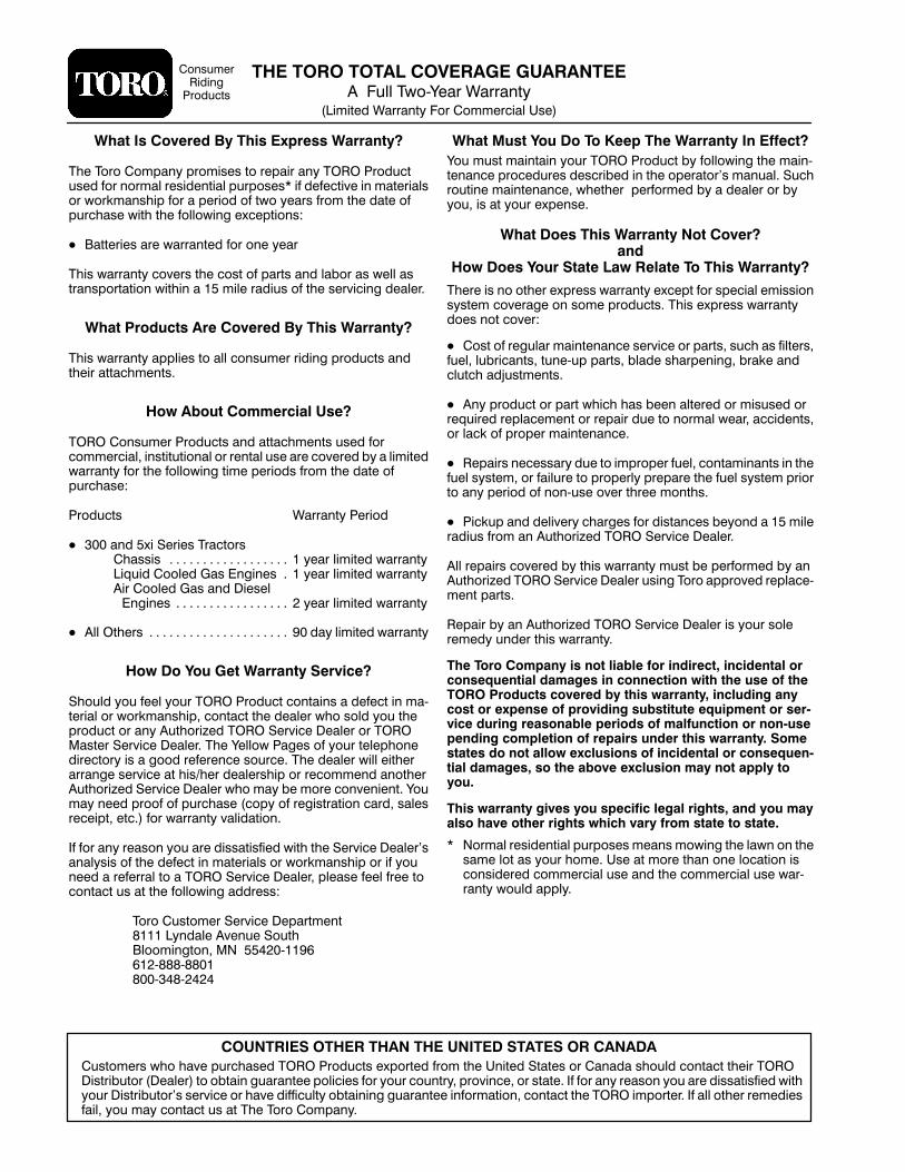
��� ����� ������ ������ �������� � �:11� "<4@%*&7� $&77&39>
��.2.9*)� $&77&39>� �47� �422*7(.&1� #8*�
�438:2*7
.).3,
�74):(98
�!�+� �,*+� �&,� �&� �&� ��'� �!�� ��))�%+0� �%� ����+�
%4:� 2:89� 2&.39&.3� >4:7� "� �� �74):(9� '>� +4114<.3,� 9-*� 2&.3@
9*3&3(*� 574(*):7*8� )*8(7.'*)� .3� 9-*� 45*7&947�8� 2&3:&1�� !:(-
74:9.3*� 2&.39*3&3(*�� <-*9-*7� � 5*7+472*)� '>� &� )*&1*7� 47� '>
>4:�� .8� &9� >4:7� *=5*38*�
�!�+� �&�*� �!"*� ��))�%+0� �&+� �&-�)��%�
�&.� �&�*� �&,)� �+�+�� ��.� ��#�+�� �&� �!"*� ��))�%+0�
"-*7*� .8� 34� 49-*7� *=57*88� <&77&39>� *=(*59� +47� 85*(.&1� *2.88.43
8>89*2� (4;*7&,*� 43� 842*� 574):(98�� "-.8� *=57*88� <&77&39>
)4*8� 349� (4;*7�
� �489� 4+� 7*,:1&7� 2&.39*3&3(*� 8*7;.(*� 47� 5&798�� 8:(-� &8� +.19*78�
+:*1�� 1:'7.(&398�� 9:3*@:5� 5&798�� '1&)*� 8-&75*3.3,�� '7&0*� &3)
(1:9(-� &)/:892*398�
� �3>� 574):(9� 47� 5&79� <-.(-� -&8� '**3� &19*7*)� 47� 2.8:8*)� 47
7*6:.7*)� 7*51&(*2*39� 47� 7*5&.7� ):*� 94� 3472&1� <*&7�� &((.)*398�
47� 1&(0� 4+� 5745*7� 2&.39*3&3(*�
� *5&.78� 3*(*88&7>� ):*� 94� .25745*7� +:*1�� (439&2.3&398� .3� 9-*
+:*1� 8>89*2�� 47� +&.1:7*� 94� 5745*71>� 57*5&7*� 9-*� +:*1� 8>89*2� 57.47
94� &3>� 5*7.4)� 4+� 343@:8*� 4;*7� 9-7**� 2439-8�
� �.(0:5� &3)� )*1.;*7>� (-&7,*8� +47� ).89&3(*8� '*>43)� &� �� 2.1*
7&).:8� +742� &3� �:9-47.?*)� "� �� !*7;.(*� �*&1*7�
�11� 7*5&.78� (4;*7*)� '>� 9-.8� <&77&39>� 2:89� '*� 5*7+472*)� '>� &3
�:9-47.?*)� "� �� !*7;.(*� �*&1*7� :8.3,� "474� &5574;*)� 7*51&(*@
2*39� 5&798�
*5&.7� '>� &3� �:9-47.?*)� "� �� !*7;.(*� �*&1*7� .8� >4:7� 841*
7*2*)>� :3)*7� 9-.8� <&77&39>�
�!�� �&)&� �&$'�%0� "*� %&+� #"��#�� �&)� "%�")��+�� "%�"��%+�#� &)�&%*�(,�%+"�#� ��$� �*� "%� �&%%��+"&%� ."+!� +!�� ,*�� &�� +!������ �)&�,�+*� �&-�)��� �0� +!"*� .�))�%+0�� "%�#,�"% � �%0�&*+� &)� �/'�%*�� &�� ')&-"�"% � *,�*+"+,+�� �(,"'$�%+� &)� *�)1-"��� �,)"% � )��*&%��#�� '�)"&�*� &�� $�#�,%�+"&%� &)� %&%1,*�'�%�"% � �&$'#�+"&%� &�� )�'�")*� ,%��)� +!"*� .�))�%+0�� �&$�*+�+�*� �&� %&+� �##&.� �/�#,*"&%*� &�� "%�"��%+�#� &)� �&%*�(,�%1+"�#� ��$� �*�� *&� +!�� ��&-�� �/�#,*"&%� $�0� %&+� �''#0� +&0&,�
�!"*� .�))�%+0� "-�*� 0&,� *'��"�"�� #� �#� )" !+*�� �%�� 0&,� $�0�#*&� !�-�� &+!�)� )" !+*� .!"�!� -�)0� �)&$� *+�+�� +&� *+�+��
� �472&1� 7*8.)*39.&1� 5:7548*8� 2*&38� 24<.3,� 9-*� 1&<3� 43� 9-*
8&2*� 149� &8� >4:7� -42*�� #8*� &9� 247*� 9-&3� 43*� 14(&9.43� .8
(438.)*7*)� (422*7(.&1� :8*� &3)� 9-*� (422*7(.&1� :8*� <&7@
7&39>� <4:1)� &551>�
�:8942*78� <-4� -&;*� 5:7(-&8*)� "� �� �74):(98� *=5479*)� +742� 9-*� #3.9*)� !9&9*8� 47� �&3&)&� 8-4:1)� (439&(9� 9-*.7� "� �
�.897.':947� ��*&1*7�� 94� 4'9&.3� ,:&7&39**� 541.(.*8� +47� >4:7� (4:397>�� 574;.3(*�� 47� 89&9*�� �+� +47� &3>� 7*&843� >4:� &7*� ).88&9.8+.*)� <.9-
>4:7� �.897.':947�8� 8*7;.(*� 47� -&;*� ).++.(:19>� 4'9&.3.3,� ,:&7&39**� .3+472&9.43�� (439&(9� 9-*� "� �� .25479*7�� �+� &11� 49-*7� 7*2*).*8
+&.1�� >4:� 2&>� (439&(9� :8� &9� "-*� "474� �425&3>�
��������� ����� ����� ��� ������ ������ ��� ������