Embed Size (px)
Citation preview

Chapter Five
Lay-up, Cooling System Serviceand Fitting Out
LAY-UP
Boats that are to be stored for more than 4 or 5weeks should be carefully prepared. This isnecessary to prevent damage to the engine and thestern drive unit from freezing, corrosion and/orfuel system contamination. Preparation for lay-upshould begin, if possible, while the boat is still inthe water.
If the boat has been removed from the water, asupply of coolant water must be made available tothe engine. This can be accomplished in one of twoways. The stern drive unit can be submerged in atest tank, or a garden hose may be attached to thecooling system using an adapter available at mostmarine supply stores.
The suggestions for lay-up preparation whichfollow are based on recommendations made byMercury Marine. See Table 1 (end of chapter) forlubricants recommended by Mercury Marine.
In-the-water Preparation
1. Start the engine. Run at idle until it reachesnormal operating temperature, then shut the engineoff. Drain the engine oil and install a new oil filter(Figure 1). See Chapter Four.
2. Refill the crankcase with the proper amount offresh SAE 20 SE or SF engine oil. Add one pint ofQuicksilver 4-cycle Engine Oil Supplement tocrankcase. See Chapter Four.3. Shut the fuel supply off at the fuel tank.4. Restart the engine and run for several minutesat 800- 1,200 t-pm to allow the oil to circulate to allinternal parts. Check for oil leaks around the newfilter while the engine is running.5. Shut the engine off and wait approximately 5minutes, then check the oil level on the dipstick(Figure 2, typical location). Add oil, if necessary, tobring the level up to the FULL mark on thedipstick.6. Remove flame arrestor cover (if so equipped)and flame arrestor (Figure 3) from carburetorintake and restart engine. Increase engine speed toa fast idle (800- 1,200 t-pm) and slowly pour a can ofQuicksilver Storage Seal into the carburetor intaketo fog the internal surfaces of the induction system.When the can of Storage Seal has approximately 2ounces left in it, decrease engine speed to a normalidle and kill the engine by quickly pouring theremaining Storage Seal into the carburetor. If theengine does not stall, shut the ignition offimmediately.

LAY-UP, COOLING SYSTEM SERVICE AND FI’lTING OUT 85

86 CHAPTER FIVE
NOTEIf Quicksilver Storage Seal is not available, pourabout one cup of SAE 20 SE or SF engine oilinto the carburetor. Kill the engine by quicklypouring in about 2 ounces of SAE 20 SE or SFengine oil.
7. Clean the flame arrestor with solvent, blow drywith compressed air (if available) and reinstall oncarburetor.8. Install a new fuel filter canister (Figure 4,typical). If equipped with a sediment bowl (Figure5, typical), remove and clean bowl, then install anew filter before reinstalling it to the fuel pump.
WARNINGBe sure to have a Coast Guard-approved fireextinguisher at hand before performing Step 9.
9. Completely drain the fuel tank of all gasoline.
WARNINGSince gasoline is an extreme fire hazard, alwaysstore it in a sealed metal container away fromheat, sparks and flame.
10. Remove boat from water, keeping bow higherthan stem if possible to assist in draining theexhaust system.
Out-of-water Preparation
1. Adjust trailer or cradle so that engine is in alevel position. Lower stem drive unit to its “down”position.
2. Loosen drive belt tension and inspect conditionof all belts. Replace as required. Tighten accessoryunit adjusting bolts without putting tension ondrive belts.
3. Drain cooling system as described in thischapter.

LAY-UP, COOLING SYSTEM SERVICE AND FITI’ING OUT 87
05
FUEL PUMP (TYPICAL) A \
and fuel filter
Yoke screw
4. Check all hoses for deterioration, cracks orother defects and replace as required.5. Remove the spark plugs and pour one ounce ofQuicksilver Storage Seal or SAE 20 SE or SF engineoil into each cylinder.6. Disconnect coil high tension lead at distributorcap (Figure 6). Ground lead and crank engine over15-20 seconds with the starter to coat cylinderwalls with oil.7. Wipe up any excess oil from plug holes. Wipe athin film of Storage Seal or SAE 20 engine oil onspark plug threads. Reinstall spark plugs andconnect coil lead.8. Remove the rocker arm cover(s) and check forsigns of condensation in the rocker arm area.Carefully wipe away any oil-water mixture found.Coat valve mechanism and inside of rocker armcover(s) generously with Storage Seal or SAE 20engine oil. Reinstall rocker arm cover(s) using newgasket(s).9. Refill cooling system as described in thischapter.10. Cover flame arrestor and carburetor with aplastic bag and tape tightly in place. This preventsmoisture from entering the carburetor and intakemanifold.11. Remove battery from boat. Tape vent holesclosed and clean battery case with baking sodasolution to remove corrosion and acid traces, thenrinse with cold water. Check electrolyte level ineach cell and top up with distilled water, ifnecessary. Cover terminals with a light coat ofpetroleum jelly. Store battery in a cool, dry place.
N O T ERemove battery from storage every 30-45 days.Check electrolyte level and slow-charge for 5-6hours at 6 amperes.
12. Tape exhaust outlets closed to preventmoisture from entering the exhaust manifolds andvalve chambers.13. Cover through-hull fuel tank ventilators withtape to help keep moisture from fuel tank.14. Clean engine exterior thoroughly and retouchany blemishes with engine touch-up paint. Apply afilm of Quicksilver Rust and Corrosion Preventiveon exterior surfaces or wipe down with a rag coatedwith Storage Seal or SAE 20 engine oil to leave alight coating on exterior surfaces.

88 CHAPTER FIVE
Stern Drive Unit
Refer to Chapter Four for location of lubricationpoints listed below.1. Insert a length of wire in drive shaft and gearhousing water drain holes to make sure they areopen.2. Lubricate the following components withQuicksilver Multipurpose Lubricant:
a. Ride-Guide steering cable end.b. Steering arm pivot socket.c. U-joint shaft and engine coupling shaft
splines.d. Drive unit upper and lower pivot pins.e. Gimbal or transmission output housing
bearing.f. Power steering control valve.
3. Lubricate U-joint bearings with Universal JointLubricant.4. Lubricate drive unit hinge pins withAnti-corrosion Grease.5. Remove propeller. Lubricate prop shaft withPerfect Seal (part No. C-92-34227) and reinstallpropeller.6. Inspect bellows condition. Replace if required.7. On I-Drives, check water pump impeller.Replace if worn, hardened or set.
CAUTIONDo not paint sacrificial zinc rings, plugs or bars,if present. These must be left unpainted in orderto prevent galvanic corrosion damage.
8. Remove all marine growths and deposits fromstem drive unit. Clean metal surfaces that havebecome exposed and cover with touch-up paint.9. Wipe or spray exterior surfaces of stem drivewith Rust and Corrosion Preventive.10. Store boat with stem drive unit in its normaloperating position. If the unit is stored in atilted-up position, the universal joint bellows maydevelop a “set” that will lead to premature bellowsfailure once the stem drive is returned to service.
COOLING SYSTEM DRAINING
The cooling system must be properly drained forstorage during the winter months in areas wheretemperatures fall below 32’ F (0’ C). If it is not, theengine block may be cracked by expansion offrozen water.
37
140 AND 161 ENGINE DRAIN
4LOCATIONS (PD$TTlDE)-
drain plug d;I”*, III~IIIIVIY
rin plug block petcock
Inline engines tend to crack horizontally justbelow the core plugs or along the upper edge belowthe cylinder head. A V-block will usually cracknear the hydraulic lifters or in the valley of theblock below the intake manifold.
The following procedures are designed to helpyou prevent unnecessary engine damage duringwinter storage.
To assure that the cooling system is completelydrained, adjust the trailer or cradle so that the frontof the engine is higher than the rear.
Standard Cooling System(Inline Engines)
1. Place containers under manifold and engineblock drain points, if space permits. This willprevent water from draining into the boat.

LAY-UP, COOLING SYSTEM SERVICE AND FITTING OUT 89
2. Open the drain valve on the port side of theengine block and remove the exhaust manifolddrain plug. Remove exhaust elbow drain plug, if soequipped. See Figure 7 for typical locations.3 . If equipped with an exhaust elbow riser, removethe drain plug from the front of the riser.4. If equipped with power steering, remove thedrain plug from the lower-aft end of the powersteering oil cooler. See Figure 8.5. Allow cooling system to completely drain, thencoat drain plug threads with Perfect Seal andreinstall. Close engine block drain valve.
Closed Cooling System(Inline Engines)
The fresh water section of a closed coolingsystem need not be drained during winter months,provided it is kept filled with a 50/50 solution ofpure soft water and ethylene glycol antifreeze.However, the seawater section must be drainedcompletely.
Seawater section(Except Models60, 470, 485 and 488)
1. Place containers under drain points, if spacepermits. This will prevent water from draining intothe boat.2. Remove the exhaust manifold drain plug.Remove the exhaust elbow drain plug, if soequipped.3. If equipped with an exhaust elbow riser, removethe drain plug at the front of the riser.4. If equipped with power steering, remove thedrain plug from the bottom of the power steeringoil cooler. See Figure 9.5. Refer to Figure 10 and disconnect the sea waterinlet hose (A), remove the drain plug from the aftend of the heat exchanger (B) and remove the zincelectrode (C), if so equipped.6. Examine zinc electrode (if so equipped) forerosion. If it is less than 25 percent eroded, coatelectrode threads with Perfect Seal and reinstall. Ifmore than 25 percent of the electrode is gone,install a new one.7. Allow seawater section to completely drain, thencoat drain plug threads with Perfect Seal andreinstall. Reconnect sea water inlet hose to heatexchanger (A, Figure 10).
08. POWER STEERING OIL COOLER DRAIN
(STANDARD COOLING SYSTEM)

90 CHAPTER FIVE
09POWER STEERING OIL COOLER DRAIN(CLOSED COOLING SYSTEM)
010HEAT EXCHANGERDRAIN LOCATIONS
A. Seawater inlet hose D. Pressure capB. Drain plug E. Circulating pump hoseC. Zinc electrode

LAY-UP, COOLING SYSTEM SERVICE AND FI’ITING OUT 91
Seawater section(Model 60)
Refer to Figure 11 or Figure 12 for thisprocedure.
1. Place containers under drain points, if possible.This will prevent water from draining into theboat.2. Remove heat exchanger drain plug.
3. Remove both drain plugs from the exhaustmanifold.4. Disconnect hose at elbow fitting on bottom ofexhaust manifold.5. Allow seawater section to completely drain, thencoat drain plug threads with Perfect Seal andreinstall.6. Reconnect hose to exhaust manifold elbowfitting.
0 11 MERCRUISER 60(STARBOARD SIDE)
0 12MERCRUISER 60 (PORT SIDE)

-
92 CHAPTER FIVE
Seawater section(Models 470, 485 and 488)
Refer to Figure 13 (serial No. 4886619 andbelow) or Figure 14 (serial No. 4886620 and above)for this procedure.1. Place containers under drain points, if spacepermits. This will prevent water from draining intothe boat.2. Remove the exhaust elbow drain plug and heatexchanger seawater drain plug.3. If equipped with an exhaust elbow riser, removethe drain plug from the front of the riser.4. On engines equipped with a water-cooledvoltage regulator (serial No. 4886620 and above),disconnect the sea water inlet hose at the regulator.5. If equipped with power steering, remove thedrain plug from the lower-aft end of the power
6. Allow seawater section to completely drain, thencoat drain plug threads with Perfect Seal andreinstall. Reconnect seawater inlet hose toregulator.
Fresh water section(except Models 60, 470, 485 and 488)
1. Place containers under drain points, if spacepermits. This will prevent coolant from draininginto the boat.2. Remove pressure fill cap from reservoir. See D,Figure 10.3. Open engine block drain valve on port side of
steering oil cooler. See Figure 8. block. See Figure 7 for typical location.
013MODEL 470 DRAIN LOCATIONS
(SERIAL NO. 4888818 AND BELOW)
A. Pressure fill cap -B. Exhaust elbow drain plugC. Exhaust manifold drain plugD. Cylinder block drain plugE. Fresh water drain plugF. Seawater drain plug0. Heat exchanger
LAYUP, COOLING SYSTEM SERVICE AND FITTING OUT 93
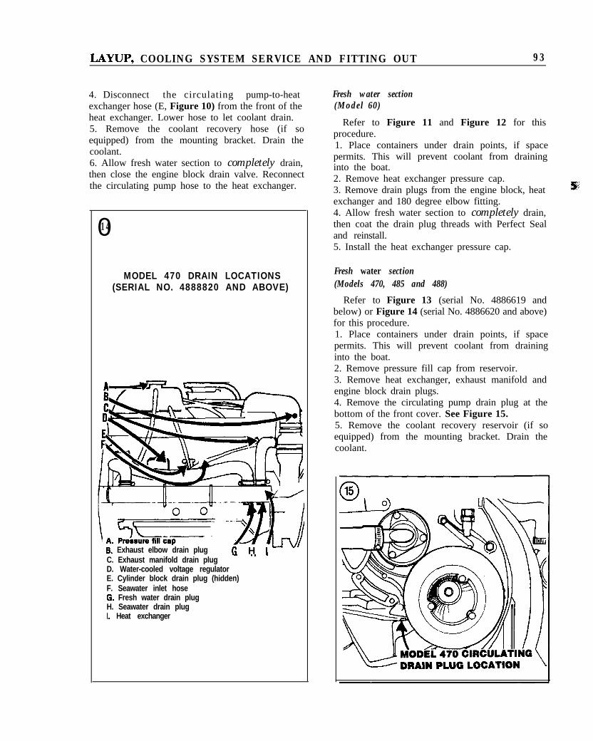
4. Disconnect the circulating pump-to-heatexchanger hose (E, Figure 10) from the front of theheat exchanger. Lower hose to let coolant drain.5. Remove the coolant recovery hose (if soequipped) from the mounting bracket. Drain thecoolant.6. Allow fresh water section to completely drain,then close the engine block drain valve. Reconnectthe circulating pump hose to the heat exchanger.
014
MODEL 470 DRAIN LOCATIONS(SERIAL NO. 4888820 AND ABOVE)
\..r --36. Exhaust elbow drain plug G H iuv’C. Exhaust manifold drain plugD. Water-cooled voltage regulatorE. Cylinder block drain plug (hidden)F. Seawater inlet hose0. Fresh water drain plugH. Seawater drain plugI. Heat exchanger
Fresh water section(Model 60)
Refer to Figure 11 and Figure 12 for thisprocedure.1. Place containers under drain points, if spacepermits. This will prevent coolant from draininginto the boat.2. Remove heat exchanger pressure cap.3. Remove drain plugs from the engine block, heatexchanger and 180 degree elbow fitting.4. Allow fresh water section to completely drain,then coat the drain plug threads with Perfect Sealand reinstall.5. Install the heat exchanger pressure cap.
Fresh water section(Models 470, 485 and 488)
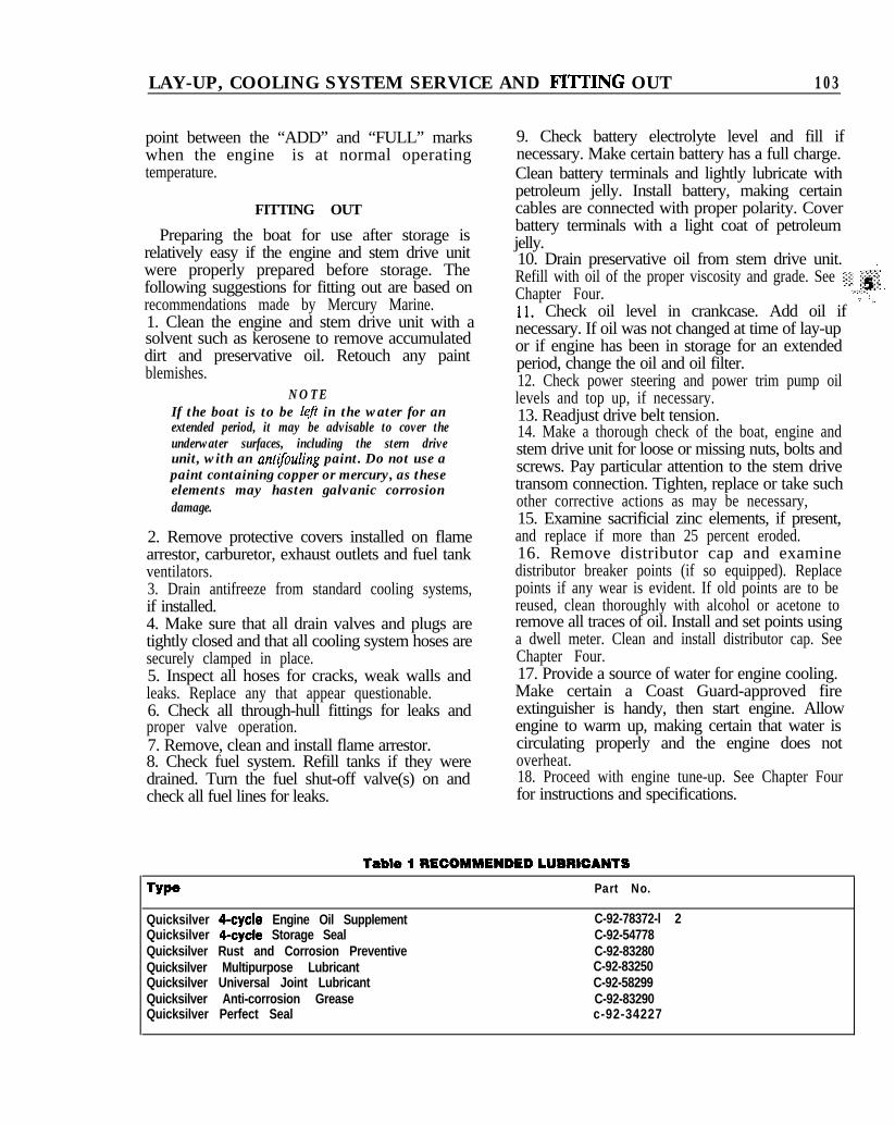
Refer to Figure 13 (serial No. 4886619 andbelow) or Figure 14 (serial No. 4886620 and above)for this procedure.1. Place containers under drain points, if spacepermits. This will prevent coolant from draininginto the boat.2. Remove pressure fill cap from reservoir.3. Remove heat exchanger, exhaust manifold andengine block drain plugs.4. Remove the circulating pump drain plug at thebottom of the front cover. See Figure 15.5. Remove the coolant recovery reservoir (if soequipped) from the mounting bracket. Drain thecoolant.

94 CHAPTER FIVE
6. Allow fresh water section to completely drain,then coat drain plug threads with Perfect Seal andreinstall.
Standard Cooling System(V6 and V8 Engines) .
Models 888, 255-S, 233,898, 228,250 and260
Refer to Figure 16 and Figure 17 (Models 888,25% and 233) or Figure 18 and Figure 19 (Models898, 228, 250 and 260) for this procedure.1. Place containers under drain points, if spacepermits. This will prevent water from draining intothe boat.2. Remove the exhaust manifold and elbow drainplugs from both sides of the engine. Open theengine block drain valve on each side of the engine.3. If equipped with exhaust elbow risers under theexhaust elbows, remove the drain plug from eachriser.
NOTE[f power steering oil cooler has no drain plug,remove hose A in Figure 18.
4A. Power steering-remove drain plug fromlower-aft end of power steering oil cooler. See B,Figure 18.4B. Non-power steering-disconnect water inlethose at thermostat housing. Lower hose to let waterdrain from the lowest part.5. Disconnect circulating pump hose at the pumpand lower the hose to drain the water.6. Allow cooling system to completely drain, thencoat drain plug threads with Perfect Seal andreinstall.7. Close engine block drain valves and reconnecthoses.
Models 225II- TR, 255II- TR(S/N 4175499 and below), 255II-TRS
Refer to Figure 19 and Figure 20 for thisprocedure.1. Place containers .under drain points, if spacepermits. This will prevent water from draining intothe boat.2. Remove the drain plug from each exhaustmanifold. Remove the port exhaust elbow drainPh3.3. Open the engine block drain valves on each sideof the engine.
016DRAIN LOCATIONS (PORT SIDE)
C. Cylinder block petcock
DRAIN LOCATIONS (STARBOARD SIDE)
A. Exhaust elbow drain plug (hidden)8. Exhaust manifold drain plugC. Thermostat housing water inlet hoseD. Cylinder block petcock (hidden)E. Thermostat housing to circulating pump hose 017

LAYUP, COOLING SYSTEM SERVICE AND FITTING OUT 93
4. Disconnect the circulating pump-to-heatexchanger hose (E, Figure 10) from the front of theheat exchanger. Lower hose to let coolant drain.5. Remove the coolant recovery hose (if soequipped) from the mounting bracket. Drain thecoolant.6. Allow fresh water section to completely drain,then close the engine block drain valve. Reconnectthe circulating pump hose to the heat exchanger.
01 4
MODEL 470 DRAIN LOCATIONS(SERIAL NO. 4888820 AND ABOVE)
C. Exhaust manifold drain plugD. Water-cooled voltage regulatorE. Cylinder block drain plug (hidden)F. Seawater inlet hose0. Fresh water drain plugH. Seawater drain plugI. Heat exchanger
Fresh water section(Model 60)
Refer to Figure 11 and Figure 12 for thisprocedure.1. Place containers under drain points, if spacepermits. This will prevent coolant from draininginto the boat.2. Remove heat exchanger pressure cap.3. Remove drain plugs from the engine block, heatexchanger and 180 degree elbow fitting.4. Allow fresh water section to completely drain,then coat the drain plug threads with Perfect Sealand reinstall.5. Install the heat exchanger pressure cap.
Fresh water section(Models 470, 485 and 488)
Refer to Figure 13 (serial No. 4886619 andbelow) or Figure 14 (serial No. 4886620 and above)for this procedure.1. Place containers under drain points, if spacepermits. This will prevent coolant from draininginto the boat.2. Remove pressure fill cap from reservoir.3. Remove heat exchanger, exhaust manifold andengine block drain plugs.4. Remove the circulating pump drain plug at thebottom of the front cover. See Figure 15.5. Remove the coolant recovery reservoir (if soequipped) from the mounting bracket. Drain thecoolant.

94 CHAPTER FIVE
6. Allow fresh water section to completely drain,then coat drain plug threads with Perfect Seal andreinstall.
Standard Cooling System(V6 and V8 Engines) .
Models 888, 255-S, 233,898, 228, 250 and 260
Refer to Figure 16 and Figure 17 (Models 888,25% and 233) or Figure 18 and Figure 19 (Models898, 228, 250 and 260) for this procedure.1. Place containers under drain points, if spacepermits. This will prevent water from draining intothe boat.2. Remove the exhaust manifold and elbow drainplugs from both sides of the engine. Open theengine block drain valve on each side of the engine.3. If equipped with exhaust elbow risers under theexhaust elbows, remove the drain plug from eachriser.
NOTEJf power steering oil cooler has no drain plug,remove hose A in Figure 18.
4A. Power steering-remove drain plug fromlower-aft end of power steering oil cooler. See B,Figure 18.4B. Non-power steering-disconnect water inlethose at thermostat housing. Lower hose to let waterdrain from the lowest part.5. Disconnect circulating pump hose at the pumpand lower the hose to drain the water.6. Allow cooling system to completely drain, thencoat drain plug threads with Perfect Seal andreinstall.7. Close engine block drain valves and reconnecthoses.
Models 225II- TR, 255II- TR(S/N 4175499 and below), 255II-TRS
Refer to Figure 19 and Figure 20 for thisprocedure.1. Place containers .under drain points, if spacepermits. This will prevent water from draining intothe boat.2. Remove the drain plug from each exhaustmanifold. Remove the port exhaust elbow drainplug.3. Open the engine block drain valves on each sideof the engine.
016DRAIN LOCATIONS (PORT SIDE)
B. Exhaust manifold drain $ugC. Cylinder block petcock
DRAIN LOCATIONS (STARBOARD SIDE)
A. Exhaust elbow drain plug (hidden)B. Exhaust manifold drain plugC. Thermostat housing water inlet hoseD. Cylinder block petcock (hidden)E. Thermostat housing to circulating pump hose 017

LAY-UP, COOLING SYSTEM SERVICE AND FI’lTING OUT 95
POWER STEERING OIL COOLER
A. Hose8. Drain plug
019
MODELS 225ll=TR, ?SSII=TR(SERIAL NO. 4175499 AND BELOW)AND 255ll-TRS DRAINLOCATIONS (PORT SIDE)
; .- . .I-N A. Exhaust elbow drain plu<
8. Exhaust manifold drain plugC. Cylinder block petcock
020
MODELS 225ll=TR, 255lbTR(SERIAL NO. 4175499 AND BELOW)AND 255IbTRS DRAIN LOCATION(STARBOARD SIDE)
A. Exhaust elbow8. Exhaust manifold drain plugC. Thermostat housing to circulating pump hoseD. Seawater pickup pumpE. Cylinder biock drain petcock (hidden)F. Power steering oil cooler drain plug0. Transmission oil coolerH. Transmission oil cooler outlet hose
4. If equipped with exhaust elbow risers under theexhaust elbows, remove the drain plug from each.5. Disconnect the circulating pump hose at thepump and lower to let the water drain.6. If equipped with power steering, remove drainplug from lower-aft end of power steering oilcooler.7. Disconnect inlet hose at aft end of sea waterpickup pump. If engine is not equipped with powersteering, also disconnect the pump outlet hose.8. Disconnect the coil secondary lead from thecenter distributor tower and ground it to the engineblock.9. Crank engine over to purge any water remainingin the seawater pickup pump.10. Remove outlet hose from transmission oilcooler fitting on starboard exhaust elbow. Lower

9 6 C H A P T E R FIVE
hose below transmission to drain water from theoil cooler.
CA UTIONIf freezing weather is anticipated during lay-up,Jill transmission oil cooler with antifreezethrough the outlet hose until it appears at thepower steering oil cooler drain (power steeringmodels) or seawater pickup pump outlet(non-power steering models). Reconnect hose.
11. After cooling system has completely drained,coat drain plug threads with Perfect Seal andreinstall plugs.12. Close engine block drain valves, reconnect allhoses and reinstall coil secondary lead.
Models 228II- TR, 255II- TR(serial No. 4175500 and above),28OII- TRS, 33OII- TR and 33OII- TRS
Refer to Figure 21 and Figure 22 for thisprocedure.1. Place containers under drain points, if spacepermits. This will prevent water from draining intothe boat.2. Remove the drain plug from each exhaustmanifold. Remove the port exhaust elbow drainplug, if so equipped.3. Open the engine block drain valves on each sideof the engine.4. Model 25511-TR and 28011-TRS engines withwater distribution blocks-remove drain plug fromeach distribution block (located under exhaustelbows). See Figure 23.5. If equipped with exhaust elbow risers, removethe drain plug from each riser.6. Disconnect the circulating pump hose at thepump and drain the hose of water.7. If equipped with power steering, remove drainplug from lower-aft end of power steering oilcooler. Late model oil coolers have no drain plug;the cooler is drained in Step 8.8. Disconnect the inlet/outlet hoses from the aftend of the sea water pickup pump.9. Disconnect the coil secondary lead from thecenter distributor tower and ground it to the engineblock.10. Crank engine over to purge any waterremaining in the sea water pickup pump.11. Remove outlet hose from transmission oilcooler fitting on starboard exhaust elbow. Lower
021MODELS 228ll=TR, 255ll=TR(SERIAL NO. 4175100 AND ABOVE),280ll=TRS, 330ll-TR AND330ll-TRS DRAIN LOCATIONS
4. Exhaust elbow drainpitig ’3. Exhaust manifold drain plug,Z. Cylinder block drain petcock (hidden)
022MODELS 228ll=TR, 25Sll=TR(SERIAL NO. 4175500 AND ABOVE),280ll=TRS, 330lbTR AND 330ll-TRSDRAIN LOCATIONS (STARBOARD SIDE)
4. Exhaust elbow drain plug (hidden)3. Exhaust manifold drain plug:. Power steering oil cooler drain plugI. Transmission oil cooler outlet hose5. Cylinder block drain petcock:. Seawater pickup pump3. Thermostat housing to circulating pump hose

LAY-UP. COOLING SYSTEM SERVICE AND FITTING OUT 97
WATER DISTRIBUTION ’ -BLOCK DRAIN PLUG
02 4
HEAT EXCHANGER DRAIN LOCATIONS-._ ?
A. Pressure%11 cap0. Heat exchanger to circulating pump hoseC. Seawater drain plugD. Zinc electrode (if so equipped)
hose below transmission to drain water from theoil cooler.
CA UTIOA’If freezing weather is anticipated during lay-up,fill transmission oil cooler with antifreezethrough the outlet hose until it appears at thepower steering oil cooler drain (power steeringmodels) or seawater pickup pump outlet(non-power steering models). Reconnect hose.
12. After cooling system has completely drained,coat drain plug threads with Perfect Seal andreinstall plugs.13. Close engine block drain valves, reconnect allhoses and reinstall coil secondary lead.
Closed Cooling System (V6 and VS Engines)
The fresh water section of a closed coolingsystem need not be drained during winter months,provided it is kept filled with a 50/50 solution ofpure soft water and ethylene glycol antifreeze.However, the seawater section must be drainedcompletely.
Seawater section(Models 888, 255S and 233)
1. Place containers under drain points, if spacepermits. This will prevent water from draining intothe boat.2. Remove both exhaust elbow drain plugs.3. If equipped with exhaust elbow risers, removethe drain plug at the front of each riser.4. If equipped with power steering, remove thedrain plug from the bottom of the power steeringoil cooler. See Figure 18. On late models without adrain plug, the oil cooler is drained during Step 7.5. Refer to Figure 24 and remove the drain plug(C) from the bottom of the heat exchanger.Remove the zinc electrode (D), if so equipped.6. Examine zinc electrode (if so equipped) forerosion. If it is less than 25 percent eroded, coatelectrode threads with Perfect Seal and reinstall. Ifmore than 25 percent of the electrode is gone,install a new one.7. Disconnect inlet hose from aft end of seawaterpickup pump. If equipped with power steering but

-
98 CHAPTER FIVE
no oil cooler drain plug, also disconnect the pumpoutlet hose. See Figure 25.8. Disconnect the coil secondary lead from thecenter distributor tower and ground it to the engineblock.9. Crank engine over to purge any water remainingin the seawater pickup pump.10. Allow seawater section to completely drain,then coat drain plug threads with Perfect Seal andreinstall plugs.11. Close engine block drain valves, reconnect allhoses and reinstall coil secondary lead.
seawater section(Models 898, 228, 250 and 260)
Refer to Figure 26 and Figure 27 for thisprocedure.1. Place containers under drain points, if spacepermits. This will prevent water from draining intothe boat.2. Remove both exhaust elbow drain plugs.3. If equipped with water distribution blocksunder exhaust elbows, remove drain plug fromeach block. See Figure 28.4. If equipped with exhaust elbow risers, removethe drain plug at the front of each riser.5. Remove the heat exchanger drain plug.6. If equipped with power steering, remove thedrain plug from the bottom of the power steeringoil cooler. See Figure 18. On late models without adrain plug, the oil cooler is drained during Step 7.7. Disconnect inlet/outlet hoses from the aft end ofthe seawater pump. Be sure to reconnect hoses totheir proper fitting.8. Disconnect the coil secondary lead from thecenter distributor tower and ground it to the engineblock.9. Crank engine over to purge any water remainingin the seawater pickup pump.10. Allow seawater section to completely drain,then coat drain plug threads with Perfect Seal andreinstall plugs.11. Close engine block drain valves, reconnect allhoses and reinstall coil secondary lead.
Models 225II- TR, 255II- TR(serial No. 4175499 and below and 255II-TRS)
1. Place containers under drain points, if spacepermits. This will prevent water from draining intothe boat.
025
A. Outlet hoseB. Inlet (hose shown disconnected)C. Seawater pickup pump
A. Exhaust elbow drain plugB. Exhaust manifold drain plugC. Cylinder block drain petcock
MODELS 898,228,2SOMODELS 898,228,2SOAND 280 ENGINE DRAIN LOCATIONSAND 280 ENGINE DRAIN LOCATIONS(STANDARD COOLING SYSTEM,(STANDARD COOLING SYSTEM,PORT SIDE)PORT SIDE)

LAY-UP, COOLING SYSTEM SERVICE AND FI’ITING OUT
027 MODELS 888,228,250 AND280 ENGINE DRAIN LOCATIONS(STANDARD COOLINQ SYSTEM,STARBOARD SIDE)
A. Exhaust elbow drain plug (hidden)B. Exhaust manifold drain plugC. Thermostat housing inlet hoseD. Thermostat housing to circulating pump hoseE. Cylinder block drain petcock
02 8
?=PASSAGE DISTRIBUTIONBLOCK DRAIN LOCATIONS
A. Water distribution blockB. Drain plug
029HEAT EXCHANGER DRAIN LOCATIONS
A. Pressure fill capB. Heat exchanger to circulating pump hoseC. Seawater drain plugD. Zinc electrode (if so equipped)
2. Remove exhaust elbow drain plug.3. If equipped with exhaust elbow risers, removethe drain plug at the front of each riser.4. If equipped with power steering, remove thedrain plug from the bottom of the power steeringoil cooler. See Figure 18. On late models without adrain plug, the oil cooler is drained during Step 7.5. Remove the drain plug from the bottom of theheat exchanger.6. Refer to Figure 29 and remove the zincelectrode (D), if so equipped. Examine zincelectrode for erosion. If it is less than 25 percenteroded, coat electrode threads with Perfect Seal andreinstall. If more than 25 percent of the electrode isgone, install a new one.7. Disconnect inlet hose from aft end of seawaterpickup pump. If equipped with power steering butno oil cooler drain plug, also disconnect the pumpoutlet hose. See Figure 25.8. Disconnect the coil secondary lead from thecenter distributor tower and ground it to the engineblock.9. Crank engine over to purge any water remainingin the seawater pickup pump.10. Remove outlet hose from transmission oilcooler fitting on starboard exhaust elbow. Lower

1 0 0 CHAPTER FIVE
hose below transmission to drain seawater from theoil cooler.
CAUTIONIf freezing weather is anticipated during lay-up,fill transmission oil cooler with antifreezethrough the outlet hose until it appears at thepower steering oil cooler drain (power steeringmodels) or seawater pickup pump outlet(non-power steering models). Reconnect hose.
11. Allow seawater section to completely drain,then coat drain plug threads with Perfect Seal andreinstall plugs.12. Reconnect all hoses and reinstall coilsecondary lead.
Seawater section(Models 228II- TR, 255II-TRserial No. 4175500 and above,28OII- TRS, 33OII- TR and 33OII- TRS)
1. Place containers under drain points, if spacepermits. This will prevent water from draining intothe boat.
N O T EOlder Model 255II- TR and 28OII- TRS enginesdo not have an exhaust elbow drain plug.
2. Remove port exhaust elbow drain plug, if soequipped.
3. Remove drain plugs from aft end of bothdistribution blocks. See Figure 28.4. If equipped with exhaust elbow risers, removethe drain plug at the front of each riser.5. If equipped with power steering, remove thedrain plug from the bottom of the power steeringoil cooler. See Figure 18. On late models without adrain plug, the oil cooler is drained during Step 8.6. Remove the drain plug from the bottom of theheat exchanger.7. Refer to Figure 29 and remove the zincelectrode (D), if so equipped. Examine zincelectrode for erosion. If it is less than 25 percenteroded, coat electrode threads with Perfect Seal andreinstall. If more than 25 percent of the electrode isgone, install a new one.8. Disconnect inlet hose from aft end of seawaterpickup pump. If equipped with power steering butno oil cooler drain plug, also disconnect the pumpoutlet hose. See Figure 25.
9. Disconnect the coil secondary lead from thecenter distributor tower and ground it to the engineblock.10. Crank engine over to purge any waterremaining in the seawater pickup pump.11. Remove outlet hose from transmission oilcooler fitting on starboard exhaust elbow. Lowerhose below transmission to drain seawater from theoil cooler.
1 2 . Allow seawater section to completely drain,
CAUTIONIf freezing weather is anticipated during lay-up,fill transmission oil cooler with antgreezethrough the outlet hose until it appears at thepower steering oil cooler drain (power steeringmodels) or seawater pickup pump outlet(non-power steering models). Reconnect hose.
then coat drain plug threads with Perfect Seal andreinstall plugs.13. Reconnect all hoses and reinstall coilsecondary lead.
Fresh water section(all V-8 engines)
Refer to Figure 16 and Figure 17 for Models 888,2553, 233, 898, 228, 250 and 260. Refer to Figure19 and Figure 20 for Models 22511-TR, 25511-TR(serial No. 4175499 and below) and 25511-TRS.Refer to Figure 21 and Figure 22 for Models22811-TR, 25511-TR (serial No. 4175500 andabove), 28011-TRS, 33011-TR and 33011-TRS.

LAY-UP, COOLING SYSTEM SERVICE AND FITTING OUT 101
1. Place containers under drain points, if possible.This prevents coolant from draining into the boat.2. Remove the pressure fill cap from the heatexchanger reservoir. See Figure 24.3. Remove exhaust manifold drain plugs and opendrain valves on both sides of the engine.4. Disconnect the circulating pump hose at thepump and drain the water in it.5. Remove the coolant recovery reservoir (if soequipped) from its mounting bracket. Drainreservoir.6. Allow fresh water section to completely drain,then coat drain plug threads with Perfect Seal andreinstall plugs.7. Close engine block drain valves and reconnectpump hose.
COOLING SYSTEM FILLING
In Preparation For Storage
Under normal circumstances, the fresh watersection of a closed cooling system would not bedrained until just before the boat is to be returnedto service from winter storage. The procedures thatfollow pertain to standard cooling systems and aredesigned to provide additional protection againstfreeze damage during winter temperatures. s
CAUTIONDo not run the engine after performing thestorage cooling service procedures that follow.Before returning the boat to service, drain thecoolant as described in this chapter and tightenall fasteners and clamps to specifications.
Mine engines
1. Remove the water distribution block cover(Figure 30, typical).2. Remove the thermostat and gasket. Discard thegasket.3. Disconnect the hose at the manifold front endcap (Figure 31, typical).4. Pour a 50/50 solution of pure soft water andethylene glycol antifreeze into the waterdistribution block until the cylinder head, blockand manifold are full.5. Reinstall thermostat with a new gasket. Tightenwater distribution block cover securely (Figure 30).6. Install the hose to the manifold front end cap(Figure 31).
V6 and V8 engines
1. Loosen the hose clamps at the front manifoldend caps. See A, Figure 32 (typical) for GM enginesand Figure 33 (typical) for Ford engines. Removehoses from end caps.2. Remove thermostat housing cover. See B,Figure 32 (typical) for GM engines and Figure 34(typical) for Ford engines.3. Remove thermostat and gasket. Discard thegasket.4. Pour a 50/50 solution of pure soft water andethylene glycol antifreeze into the thermostathousing until it is full.5. Pour the coolant solution into the opening ofeach manifold end cap until the level reaches thetop of the cap.

102 CHAPTER FIVE
6. Install the thermostat with a new gasket.Tighten the thermostat housing cover screwssnugly (B, Figure 32 or Figure 34, typical).7. Connect the hoses to the front manifold endcaps and snug down the clamps (A, Figure 32 orFigure 33, typical).
Returning Engine to Service
Most ethylene glycol antifreeze solutions used inclosed cooling systems tend to become corrosive toaluminum after approximately 3 years of use or if ablown head gasket allows exhaust gases to enter thecooling system. While such corrosive tendencieswill not cause significant damage to the engine,they do produce loose particles that can eventuallyplug the coolant side of the heat exchanger.
The increasing usage of aluminum componentsin engines, water pumps, manifolds and radiatorshas led to the development of an antifreeze formularecommended for use with aluminum engines.
Mercury Marine recommends that this new typeantifreeze formulation be used in all Met-Cruiserclosed cooling systems. Check the antifreezecontainer to see if it meets one of the majorautomakers’ specifications, such as Fordspecification ESE-M97B44-A or GM specification1825M.1. Remove the pressure fill cap from the reservoiror heat exchanger.2. Fill the fresh water section with a 50/50 mixtureof pure soft water and ethylene glycol antifreezeuntil the fluid level reaches the top of the fillerneck.
CAUTIONWater must flow through seawater pump in Step3 or possible damage to the pump and enginemay result.
3. Start the engine and run at fast idle (l,OOO- 1,500rpm), adding coolant to the reservoir or heatexchanger as necessary to maintain the coolantlevel at the top of the filler neck. When enginereaches normal operating temperature and coolantlevel remains constant, reinstall pressure fill cap.4. If equipped with a coolant recovery system,remove the reservoir cap and fill with coolant tothe “FULL” mark on the reservoir.
5. Check for leaks while the engine is running andnote the position of the engine temperaturegauge-it should be normal.
WARNINGDo not remove the pressure Jill cap when theengine is warm or hot. You may be seriouslyscalded or burned by coolant escaping underpressure.
6. Shut engine off and allow to cool for 30 minutes.Turn pressure fill cap to first detent and allow anypressure to escape, then remove the cap.7. Recheck the coolant level in the reservoir orheat exchanger and add coolant as required tobring the level to the top of the filler neck.8. If equipped with a coolant recovery system, addcoolant as required to bring the reservoir level to a
LAY-UP, COOLING SYSTEM SERVICE AND FI’lTING OUT 103
point between the “ADD” and “FULL” markswhen the engine is at normal operatingtemperature.
FITTING OUT
Preparing the boat for use after storage isrelatively easy if the engine and stem drive unitwere properly prepared before storage. Thefollowing suggestions for fitting out are based onrecommendations made by Mercury Marine.1. Clean the engine and stem drive unit with asolvent such as kerosene to remove accumulateddirt and preservative oil. Retouch any paintblemishes.
NOTEIf the boat is to be left in the water for anextended period, it may be advisable to cover theunderwater surfaces, including the stern driveunit, with an antifouling paint. Do not use apaint containing copper or mercury, as theseelements may hasten galvanic corrosiondamage.
2. Remove protective covers installed on flamearrestor, carburetor, exhaust outlets and fuel tankventilators.3. Drain antifreeze from standard cooling systems,if installed.4. Make sure that all drain valves and plugs aretightly closed and that all cooling system hoses aresecurely clamped in place.5. Inspect all hoses for cracks, weak walls andleaks. Replace any that appear questionable.6. Check all through-hull fittings for leaks andproper valve operation.7. Remove, clean and install flame arrestor.8. Check fuel system. Refill tanks if they weredrained. Turn the fuel shut-off valve(s) on andcheck all fuel lines for leaks.
9. Check battery electrolyte level and fill ifnecessary. Make certain battery has a full charge.Clean battery terminals and lightly lubricate withpetroleum jelly. Install battery, making certaincables are connected with proper polarity. Coverbattery terminals with a light coat of petroleumjelly.10. Drain preservative oil from stem drive unit. ^Refill with oil of the proper viscosity and grade. See :‘i:, :0c$cSChapter Four. ,..,, ’:Il. Check oil level in crankcase. Add oil if V ”necessary. If oil was not changed at time of lay-upor if engine has been in storage for an extendedperiod, change the oil and oil filter.12. Check power steering and power trim pump oillevels and top up, if necessary.13. Readjust drive belt tension.14. Make a thorough check of the boat, engine andstem drive unit for loose or missing nuts, bolts andscrews. Pay particular attention to the stem drivetransom connection. Tighten, replace or take suchother corrective actions as may be necessary,15. Examine sacrificial zinc elements, if present,and replace if more than 25 percent eroded.16. Remove distributor cap and examinedistributor breaker points (if so equipped). Replacepoints if any wear is evident. If old points are to bereused, clean thoroughly with alcohol or acetone toremove all traces of oil. Install and set points usinga dwell meter. Clean and install distributor cap. SeeChapter Four.17. Provide a source of water for engine cooling.Make certain a Coast Guard-approved fireextinguisher is handy, then start engine. Allowengine to warm up, making certain that water iscirculating properly and the engine does notoverheat.18. Proceed with engine tune-up. See Chapter Fourfor instructions and specifications.
Type Part No.
Quicksilver 4-cycle Engine Oil SupplementQuicksilver 4-cycle Storage SealQuicksilver Rust and Corrosion PreventiveQuicksilver Multipurpose LubricantQuicksilver Universal Joint LubricantQuicksilver Anti-corrosion GreaseQuicksilver Perfect Seal
C-92-78372-l 2C-92-54778C-92-83280C-92-83250C-92-58299C-92-83290c-92-34227