Embed Size (px)
Citation preview
Layer 2 Control Protocol Peering, Forwarding,and Tunneling
This feature module describes how to configure Layer 2 (L2) Control Protocol Peering, Forwarding, andTunneling feature on the Cisco ASR 901 Series Aggregation Services Routers.
• Finding Feature Information, on page 1• Prerequisites for Layer 2 Control Protocol Peering, Forwarding, and Tunneling, on page 1• Restrictions for Layer 2 Control Protocol Peering, Forwarding, and Tunneling, on page 2• Layer 2 Control Protocol Forwarding, on page 2• Layer 2 Control Protocol Tunneling, on page 2• How to Configure Layer 2 Control Protocol Peering, Forwarding, and Tunneling, on page 3• Configuration Examples, on page 10• Additional References, on page 13• Feature Information for Layer 2 Control Protocol Peering, Forwarding, and Tunneling, on page 14
Finding Feature InformationYour software release may not support all the features documented in this module. For the latest featureinformation and caveats, see the release notes for your platform and software release. To find informationabout the features documented in this module, and to see a list of the releases in which each feature is supported,see the Feature Information for Layer 2 Control Protocol Peering, Forwarding, and Tunneling, on page 14.
Use Cisco Feature Navigator to find information about platform support and Cisco software image support.To access Cisco Feature Navigator, go to http://www.cisco.com/go/cfn. An account on Cisco.com is notrequired.
Prerequisites for Layer 2 Control Protocol Peering, Forwarding,and Tunneling
• A Cisco IOS software that supports Layer 2 Control Protocol Peering, Forwarding, and Tunneling mustbe installed previously on the Cisco ASR 901 Series Aggregation Services Router. For supported softwarereleases, see Release Notes for Cisco ASR 901 Series Aggregation Services Router.
Layer 2 Control Protocol Peering, Forwarding, and Tunneling1
Restrictions for Layer 2 Control Protocol Peering, Forwarding,and Tunneling
• If you want to peer Operation, Administration, andMaintenance (OAM) packets when l2proto-forwardtagged command is configured at the interface level, you should also configure the l2protocol peer lacpcommand.
• Received L2CP Control Packets (like STP, CDP, and others) are not mirrored to the destination port.
• Forwarding L2CP tunneled packets over x-connect is not supported.
Layer 2 Control Protocol ForwardingThe ASR 901 forwards Layer 2 Control Protocol (L2CP) packets between customer-edge (CE) devices. CiscoASR 901 router supports L2CP forwarding on Bridge-domain EVCs and on Cross-connect EVCs.
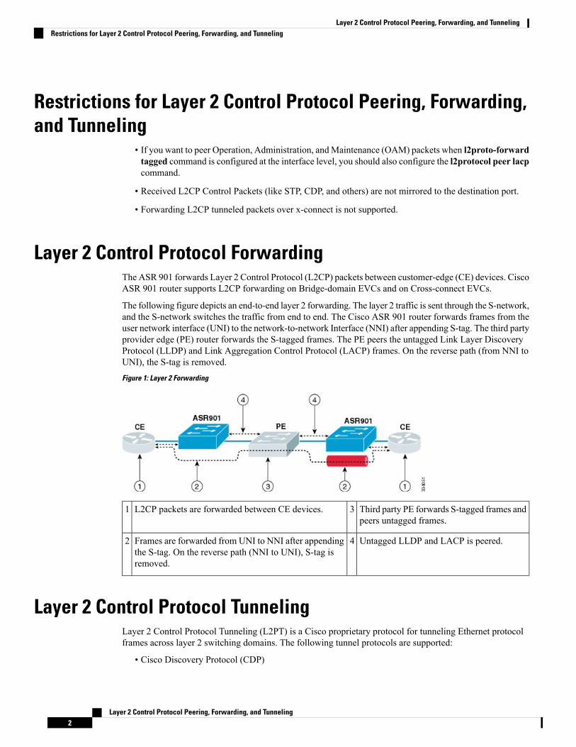
The following figure depicts an end-to-end layer 2 forwarding. The layer 2 traffic is sent through the S-network,and the S-network switches the traffic from end to end. The Cisco ASR 901 router forwards frames from theuser network interface (UNI) to the network-to-network Interface (NNI) after appending S-tag. The third partyprovider edge (PE) router forwards the S-tagged frames. The PE peers the untagged Link Layer DiscoveryProtocol (LLDP) and Link Aggregation Control Protocol (LACP) frames. On the reverse path (from NNI toUNI), the S-tag is removed.Figure 1: Layer 2 Forwarding
Third party PE forwards S-tagged frames andpeers untagged frames.
3L2CP packets are forwarded between CE devices.1
Untagged LLDP and LACP is peered.4Frames are forwarded from UNI to NNI after appendingthe S-tag. On the reverse path (NNI to UNI), S-tag isremoved.
2
Layer 2 Control Protocol TunnelingLayer 2 Control Protocol Tunneling (L2PT) is a Cisco proprietary protocol for tunneling Ethernet protocolframes across layer 2 switching domains. The following tunnel protocols are supported:
• Cisco Discovery Protocol (CDP)
Layer 2 Control Protocol Peering, Forwarding, and Tunneling2
Layer 2 Control Protocol Peering, Forwarding, and TunnelingRestrictions for Layer 2 Control Protocol Peering, Forwarding, and Tunneling
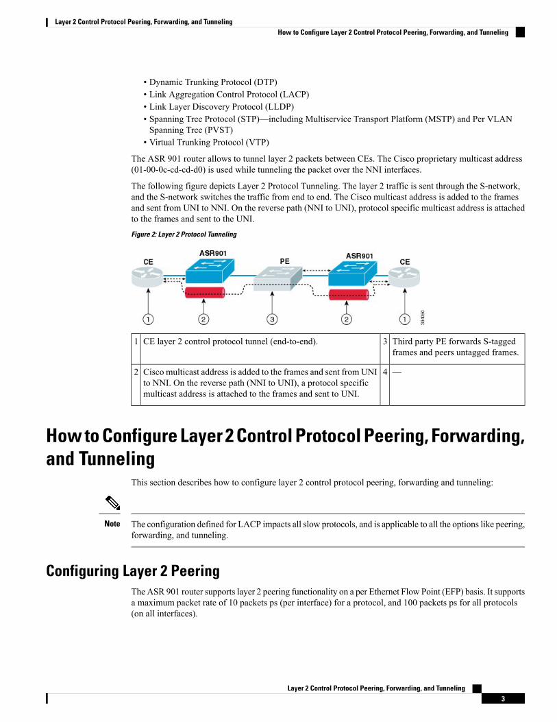
• Dynamic Trunking Protocol (DTP)• Link Aggregation Control Protocol (LACP)• Link Layer Discovery Protocol (LLDP)• Spanning Tree Protocol (STP)—including Multiservice Transport Platform (MSTP) and Per VLANSpanning Tree (PVST)
• Virtual Trunking Protocol (VTP)
The ASR 901 router allows to tunnel layer 2 packets between CEs. The Cisco proprietary multicast address(01-00-0c-cd-cd-d0) is used while tunneling the packet over the NNI interfaces.
The following figure depicts Layer 2 Protocol Tunneling. The layer 2 traffic is sent through the S-network,and the S-network switches the traffic from end to end. The Cisco multicast address is added to the framesand sent from UNI to NNI. On the reverse path (NNI to UNI), protocol specific multicast address is attachedto the frames and sent to the UNI.Figure 2: Layer 2 Protocol Tunneling
Third party PE forwards S-taggedframes and peers untagged frames.
3CE layer 2 control protocol tunnel (end-to-end).1
—4Cisco multicast address is added to the frames and sent from UNIto NNI. On the reverse path (NNI to UNI), a protocol specificmulticast address is attached to the frames and sent to UNI.
2
How to Configure Layer 2 Control Protocol Peering, Forwarding,and Tunneling
This section describes how to configure layer 2 control protocol peering, forwarding and tunneling:
The configuration defined for LACP impacts all slow protocols, and is applicable to all the options like peering,forwarding, and tunneling.
Note
Configuring Layer 2 PeeringThe ASR 901 router supports layer 2 peering functionality on a per Ethernet Flow Point (EFP) basis. It supportsa maximum packet rate of 10 packets ps (per interface) for a protocol, and 100 packets ps for all protocols(on all interfaces).
Layer 2 Control Protocol Peering, Forwarding, and Tunneling3
Layer 2 Control Protocol Peering, Forwarding, and TunnelingHow to Configure Layer 2 Control Protocol Peering, Forwarding, and Tunneling
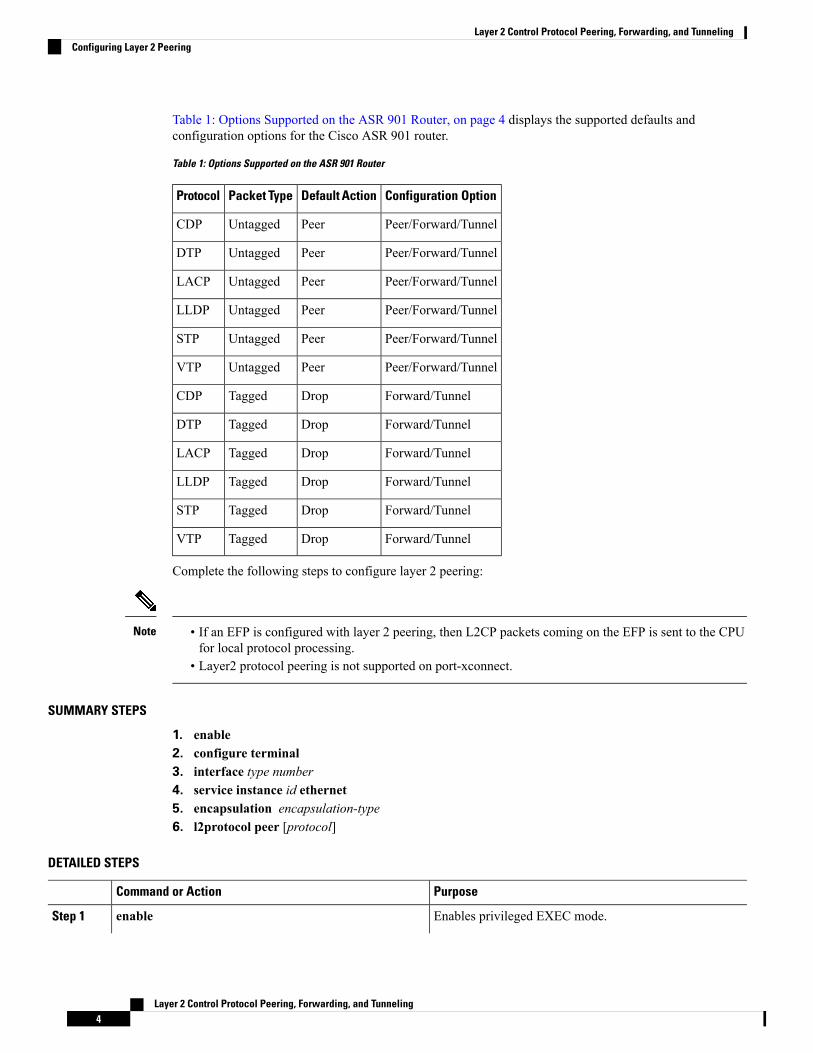
Table 1: Options Supported on the ASR 901 Router, on page 4 displays the supported defaults andconfiguration options for the Cisco ASR 901 router.
Table 1: Options Supported on the ASR 901 Router
Configuration OptionDefault ActionPacket TypeProtocol
Peer/Forward/TunnelPeerUntaggedCDP
Peer/Forward/TunnelPeerUntaggedDTP
Peer/Forward/TunnelPeerUntaggedLACP
Peer/Forward/TunnelPeerUntaggedLLDP
Peer/Forward/TunnelPeerUntaggedSTP
Peer/Forward/TunnelPeerUntaggedVTP
Forward/TunnelDropTaggedCDP
Forward/TunnelDropTaggedDTP
Forward/TunnelDropTaggedLACP
Forward/TunnelDropTaggedLLDP
Forward/TunnelDropTaggedSTP
Forward/TunnelDropTaggedVTP
Complete the following steps to configure layer 2 peering:
• If an EFP is configured with layer 2 peering, then L2CP packets coming on the EFP is sent to the CPUfor local protocol processing.
• Layer2 protocol peering is not supported on port-xconnect.
Note
SUMMARY STEPS
1. enable2. configure terminal3. interface type number4. service instance id ethernet5. encapsulation encapsulation-type6. l2protocol peer [protocol]
DETAILED STEPS
PurposeCommand or Action
Enables privileged EXEC mode.enableStep 1
Layer 2 Control Protocol Peering, Forwarding, and Tunneling4
Layer 2 Control Protocol Peering, Forwarding, and TunnelingConfiguring Layer 2 Peering
PurposeCommand or Action
Example: • Enter your password if prompted.
Router> enable
Enters global configuration mode.configure terminal
Example:
Step 2
Router# configure terminal
Specifies an interface type and number and enters interfaceconfiguration mode.
interface type number
Example:
Step 3
Router(config)# interface gigabitethernet 0/6
Configures an Ethernet service instance on an interface.service instance id ethernetStep 4
Example: • id—Integer that uniquely identifies a service instanceon an interface.
Router(config-if)# service instance 20 ethernet
Defines the matching criteria to map untagged ingressEthernet frames on an interface to the appropriate serviceinstance.
encapsulation encapsulation-type
Example:
Router(config-if-srv)# encapsulation untagged
Step 5
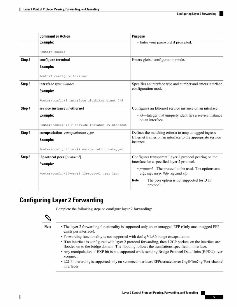
Configures transparent Layer 2 protocol peering on theinterface for a specified layer 2 protocol.
l2protocol peer [protocol]
Example:
Step 6
• protocol—The protocol to be used. The options are:cdp, dtp, lacp, lldp, stp,and vtp.Router(config-if-srv)# l2protocol peer lacp
The peer option is not supported for DTPprotocol.
Note
Configuring Layer 2 ForwardingComplete the following steps to configure layer 2 forwarding:
• The layer 2 forwarding functionality is supported only on an untagged EFP (Only one untagged EFPexists per interface).
• Forwarding functionality is not supported with dot1q VLAN range encapsulation.• If an interface is configured with layer 2 protocol forwarding, then L2CP packets on the interface areflooded on to the bridge domain. The flooding follows the translations specified in interface.
• Any manipulation of EXP bit is not supported while sending Bridge Protocol Data Units (BPDU) overxconnect.
• L2CP forwarding is supported only on xconnect interfaces/EFPs created over GigE/TenGig/Port-channelinterfaces.
Note
Layer 2 Control Protocol Peering, Forwarding, and Tunneling5
Layer 2 Control Protocol Peering, Forwarding, and TunnelingConfiguring Layer 2 Forwarding
SUMMARY STEPS
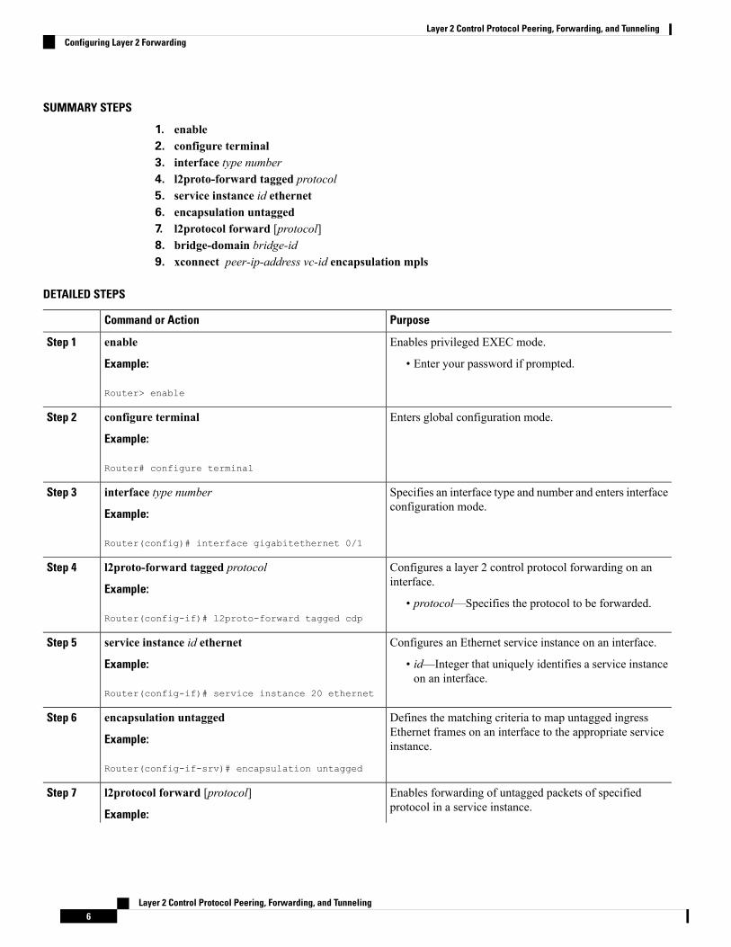
1. enable2. configure terminal3. interface type number4. l2proto-forward tagged protocol5. service instance id ethernet6. encapsulation untagged7. l2protocol forward [protocol]8. bridge-domain bridge-id9. xconnect peer-ip-address vc-id encapsulation mpls
DETAILED STEPS
PurposeCommand or Action
Enables privileged EXEC mode.enableStep 1
Example: • Enter your password if prompted.
Router> enable
Enters global configuration mode.configure terminal
Example:
Step 2
Router# configure terminal
Specifies an interface type and number and enters interfaceconfiguration mode.
interface type number
Example:
Step 3
Router(config)# interface gigabitethernet 0/1
Configures a layer 2 control protocol forwarding on aninterface.
l2proto-forward tagged protocol
Example:
Step 4
• protocol—Specifies the protocol to be forwarded.Router(config-if)# l2proto-forward tagged cdp
Configures an Ethernet service instance on an interface.service instance id ethernetStep 5
Example: • id—Integer that uniquely identifies a service instanceon an interface.
Router(config-if)# service instance 20 ethernet
Defines the matching criteria to map untagged ingressEthernet frames on an interface to the appropriate serviceinstance.
encapsulation untagged
Example:
Router(config-if-srv)# encapsulation untagged
Step 6
Enables forwarding of untagged packets of specifiedprotocol in a service instance.
l2protocol forward [protocol]
Example:
Step 7
Layer 2 Control Protocol Peering, Forwarding, and Tunneling6
Layer 2 Control Protocol Peering, Forwarding, and TunnelingConfiguring Layer 2 Forwarding
PurposeCommand or Action
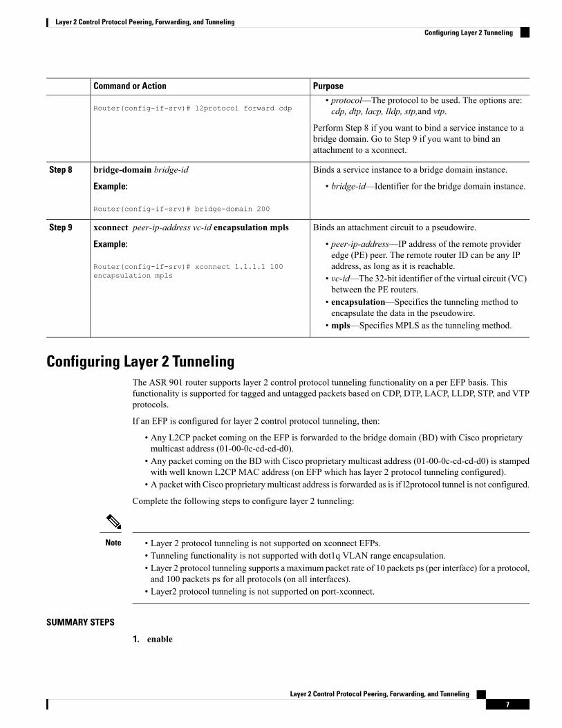
Router(config-if-srv)# l2protocol forward cdp• protocol—The protocol to be used. The options are:cdp, dtp, lacp, lldp, stp,and vtp.
Perform Step 8 if you want to bind a service instance to abridge domain. Go to Step 9 if you want to bind anattachment to a xconnect.
Binds a service instance to a bridge domain instance.bridge-domain bridge-idStep 8
Example: • bridge-id—Identifier for the bridge domain instance.
Router(config-if-srv)# bridge-domain 200
Binds an attachment circuit to a pseudowire.xconnect peer-ip-address vc-id encapsulation mplsStep 9
Example: • peer-ip-address—IP address of the remote provideredge (PE) peer. The remote router ID can be any IPaddress, as long as it is reachable.Router(config-if-srv)# xconnect 1.1.1.1 100
encapsulation mpls • vc-id—The 32-bit identifier of the virtual circuit (VC)between the PE routers.
• encapsulation—Specifies the tunneling method toencapsulate the data in the pseudowire.
• mpls—Specifies MPLS as the tunneling method.
Configuring Layer 2 TunnelingThe ASR 901 router supports layer 2 control protocol tunneling functionality on a per EFP basis. Thisfunctionality is supported for tagged and untagged packets based on CDP, DTP, LACP, LLDP, STP, and VTPprotocols.
If an EFP is configured for layer 2 control protocol tunneling, then:
• Any L2CP packet coming on the EFP is forwarded to the bridge domain (BD) with Cisco proprietarymulticast address (01-00-0c-cd-cd-d0).
• Any packet coming on the BD with Cisco proprietary multicast address (01-00-0c-cd-cd-d0) is stampedwith well known L2CP MAC address (on EFP which has layer 2 protocol tunneling configured).
• A packet with Cisco proprietary multicast address is forwarded as is if l2protocol tunnel is not configured.
Complete the following steps to configure layer 2 tunneling:
• Layer 2 protocol tunneling is not supported on xconnect EFPs.• Tunneling functionality is not supported with dot1q VLAN range encapsulation.• Layer 2 protocol tunneling supports a maximum packet rate of 10 packets ps (per interface) for a protocol,and 100 packets ps for all protocols (on all interfaces).
• Layer2 protocol tunneling is not supported on port-xconnect.
Note
SUMMARY STEPS
1. enable
Layer 2 Control Protocol Peering, Forwarding, and Tunneling7
Layer 2 Control Protocol Peering, Forwarding, and TunnelingConfiguring Layer 2 Tunneling
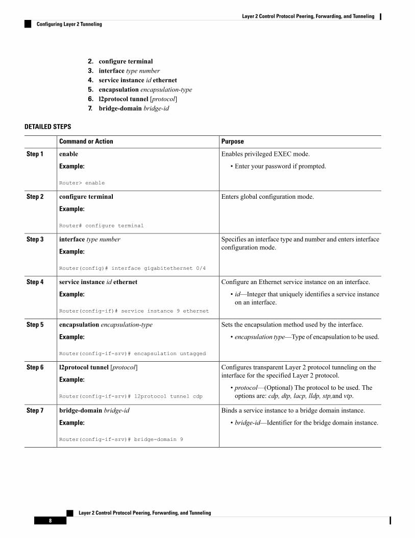
2. configure terminal3. interface type number4. service instance id ethernet5. encapsulation encapsulation-type6. l2protocol tunnel [protocol]7. bridge-domain bridge-id
DETAILED STEPS
PurposeCommand or Action
Enables privileged EXEC mode.enableStep 1
Example: • Enter your password if prompted.
Router> enable
Enters global configuration mode.configure terminal
Example:
Step 2
Router# configure terminal
Specifies an interface type and number and enters interfaceconfiguration mode.
interface type number
Example:
Step 3
Router(config)# interface gigabitethernet 0/4
Configure an Ethernet service instance on an interface.service instance id ethernetStep 4
Example: • id—Integer that uniquely identifies a service instanceon an interface.
Router(config-if)# service instance 9 ethernet
Sets the encapsulation method used by the interface.encapsulation encapsulation-typeStep 5
Example: • encapsulation type—Type of encapsulation to be used.
Router(config-if-srv)# encapsulation untagged
Configures transparent Layer 2 protocol tunneling on theinterface for the specified Layer 2 protocol.
l2protocol tunnel [protocol]
Example:
Step 6
• protocol—(Optional) The protocol to be used. Theoptions are: cdp, dtp, lacp, lldp, stp,and vtp.Router(config-if-srv)# l2protocol tunnel cdp
Binds a service instance to a bridge domain instance.bridge-domain bridge-idStep 7
Example: • bridge-id—Identifier for the bridge domain instance.
Router(config-if-srv)# bridge-domain 9
Layer 2 Control Protocol Peering, Forwarding, and Tunneling8
Layer 2 Control Protocol Peering, Forwarding, and TunnelingConfiguring Layer 2 Tunneling
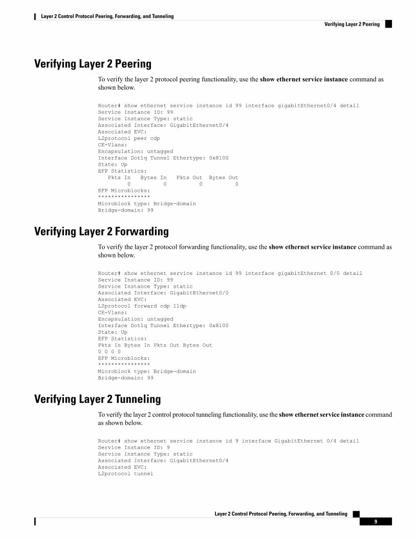
Verifying Layer 2 PeeringTo verify the layer 2 protocol peering functionality, use the show ethernet service instance command asshown below.
Router# show ethernet service instance id 99 interface gigabitEthernet0/4 detailService Instance ID: 99Service Instance Type: staticAssociated Interface: GigabitEthernet0/4Associated EVC:L2protocol peer cdpCE-Vlans:Encapsulation: untaggedInterface Dot1q Tunnel Ethertype: 0x8100State: UpEFP Statistics:
Pkts In Bytes In Pkts Out Bytes Out0 0 0 0
EFP Microblocks:****************Microblock type: Bridge-domainBridge-domain: 99
Verifying Layer 2 ForwardingTo verify the layer 2 protocol forwarding functionality, use the show ethernet service instance command asshown below.
Router# show ethernet service instance id 99 interface gigabitEthernet 0/0 detailService Instance ID: 99Service Instance Type: staticAssociated Interface: GigabitEthernet0/0Associated EVC:L2protocol forward cdp lldpCE-Vlans:Encapsulation: untaggedInterface Dot1q Tunnel Ethertype: 0x8100State: UpEFP Statistics:Pkts In Bytes In Pkts Out Bytes Out0 0 0 0EFP Microblocks:****************Microblock type: Bridge-domainBridge-domain: 99
Verifying Layer 2 TunnelingTo verify the layer 2 control protocol tunneling functionality, use the show ethernet service instance commandas shown below.
Router# show ethernet service instance id 9 interface GigabitEthernet 0/4 detailService Instance ID: 9Service Instance Type: staticAssociated Interface: GigabitEthernet0/4Associated EVC:L2protocol tunnel
Layer 2 Control Protocol Peering, Forwarding, and Tunneling9
Layer 2 Control Protocol Peering, Forwarding, and TunnelingVerifying Layer 2 Peering
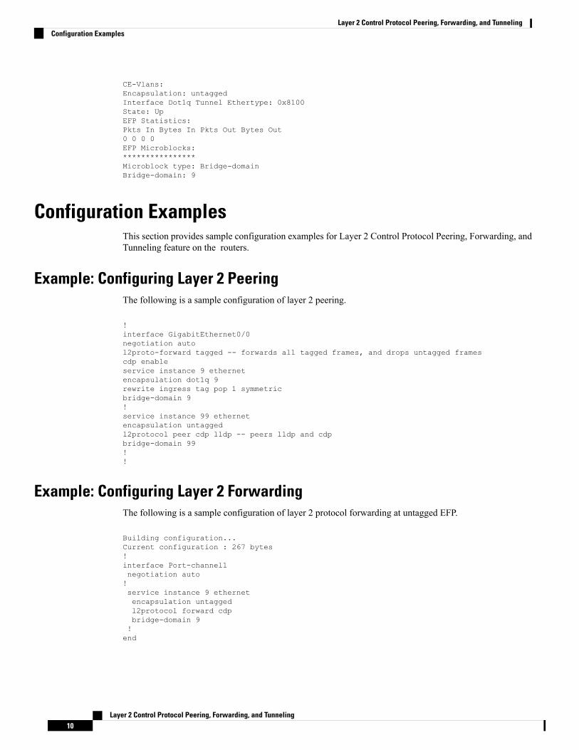
CE-Vlans:Encapsulation: untaggedInterface Dot1q Tunnel Ethertype: 0x8100State: UpEFP Statistics:Pkts In Bytes In Pkts Out Bytes Out0 0 0 0EFP Microblocks:****************Microblock type: Bridge-domainBridge-domain: 9
Configuration ExamplesThis section provides sample configuration examples for Layer 2 Control Protocol Peering, Forwarding, andTunneling feature on the routers.
Example: Configuring Layer 2 PeeringThe following is a sample configuration of layer 2 peering.
!interface GigabitEthernet0/0negotiation autol2proto-forward tagged -- forwards all tagged frames, and drops untagged framescdp enableservice instance 9 ethernetencapsulation dot1q 9rewrite ingress tag pop 1 symmetricbridge-domain 9!service instance 99 ethernetencapsulation untaggedl2protocol peer cdp lldp -- peers lldp and cdpbridge-domain 99!!
Example: Configuring Layer 2 ForwardingThe following is a sample configuration of layer 2 protocol forwarding at untagged EFP.
Building configuration...Current configuration : 267 bytes!interface Port-channel1negotiation auto!service instance 9 ethernetencapsulation untaggedl2protocol forward cdpbridge-domain 9!end
Layer 2 Control Protocol Peering, Forwarding, and Tunneling10
Layer 2 Control Protocol Peering, Forwarding, and TunnelingConfiguration Examples
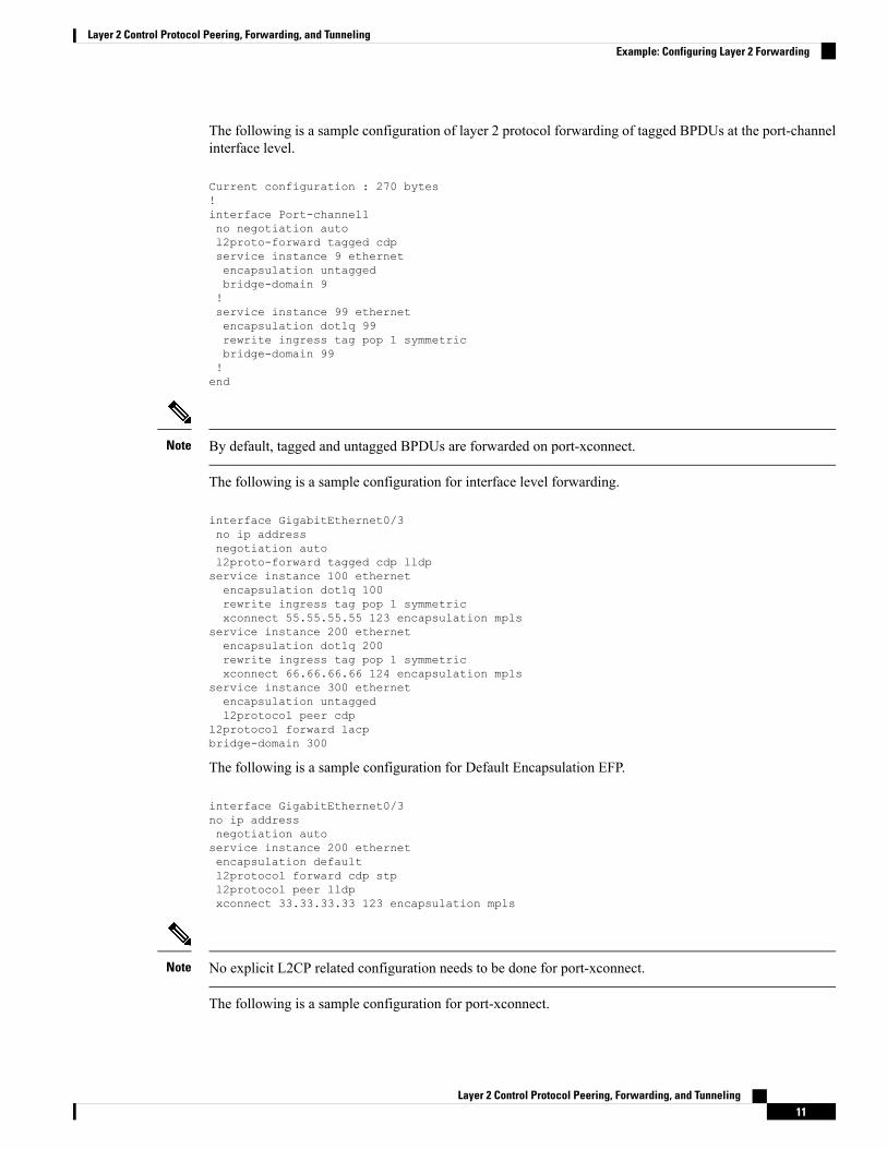
The following is a sample configuration of layer 2 protocol forwarding of tagged BPDUs at the port-channelinterface level.
Current configuration : 270 bytes!interface Port-channel1no negotiation autol2proto-forward tagged cdpservice instance 9 ethernetencapsulation untaggedbridge-domain 9!service instance 99 ethernetencapsulation dot1q 99rewrite ingress tag pop 1 symmetricbridge-domain 99!end
By default, tagged and untagged BPDUs are forwarded on port-xconnect.Note
The following is a sample configuration for interface level forwarding.
interface GigabitEthernet0/3no ip addressnegotiation autol2proto-forward tagged cdp lldpservice instance 100 ethernetencapsulation dot1q 100rewrite ingress tag pop 1 symmetricxconnect 55.55.55.55 123 encapsulation mpls
service instance 200 ethernetencapsulation dot1q 200rewrite ingress tag pop 1 symmetricxconnect 66.66.66.66 124 encapsulation mpls
service instance 300 ethernetencapsulation untaggedl2protocol peer cdp
l2protocol forward lacpbridge-domain 300
The following is a sample configuration for Default Encapsulation EFP.
interface GigabitEthernet0/3no ip addressnegotiation autoservice instance 200 ethernetencapsulation defaultl2protocol forward cdp stpl2protocol peer lldpxconnect 33.33.33.33 123 encapsulation mpls
No explicit L2CP related configuration needs to be done for port-xconnect.Note
The following is a sample configuration for port-xconnect.
Layer 2 Control Protocol Peering, Forwarding, and Tunneling11
Layer 2 Control Protocol Peering, Forwarding, and TunnelingExample: Configuring Layer 2 Forwarding
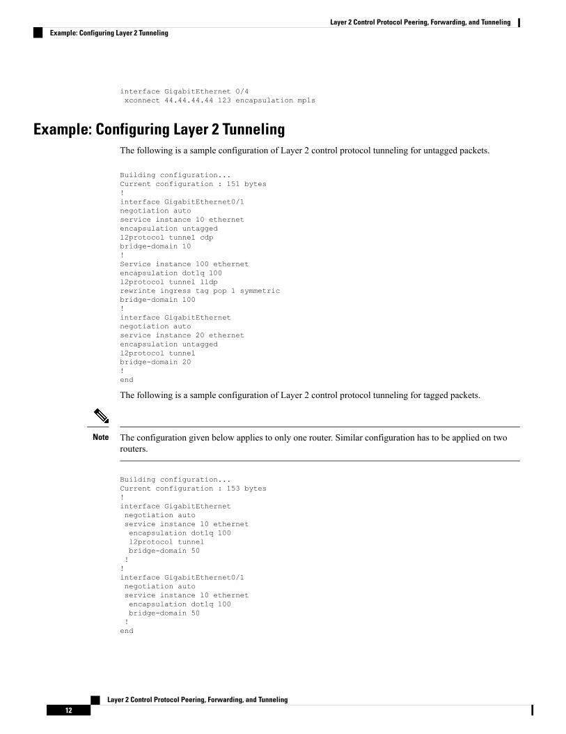
interface GigabitEthernet 0/4xconnect 44.44.44.44 123 encapsulation mpls
Example: Configuring Layer 2 TunnelingThe following is a sample configuration of Layer 2 control protocol tunneling for untagged packets.
Building configuration...Current configuration : 151 bytes!interface GigabitEthernet0/1negotiation autoservice instance 10 ethernetencapsulation untaggedl2protocol tunnel cdpbridge-domain 10!Service instance 100 ethernetencapsulation dot1q 100l2protocol tunnel lldprewrinte ingress tag pop 1 symmetricbridge-domain 100!interface GigabitEthernetnegotiation autoservice instance 20 ethernetencapsulation untaggedl2protocol tunnelbridge-domain 20!end
The following is a sample configuration of Layer 2 control protocol tunneling for tagged packets.
The configuration given below applies to only one router. Similar configuration has to be applied on tworouters.
Note
Building configuration...Current configuration : 153 bytes!interface GigabitEthernetnegotiation autoservice instance 10 ethernetencapsulation dot1q 100l2protocol tunnelbridge-domain 50!!interface GigabitEthernet0/1negotiation autoservice instance 10 ethernetencapsulation dot1q 100bridge-domain 50!end
Layer 2 Control Protocol Peering, Forwarding, and Tunneling12
Layer 2 Control Protocol Peering, Forwarding, and TunnelingExample: Configuring Layer 2 Tunneling
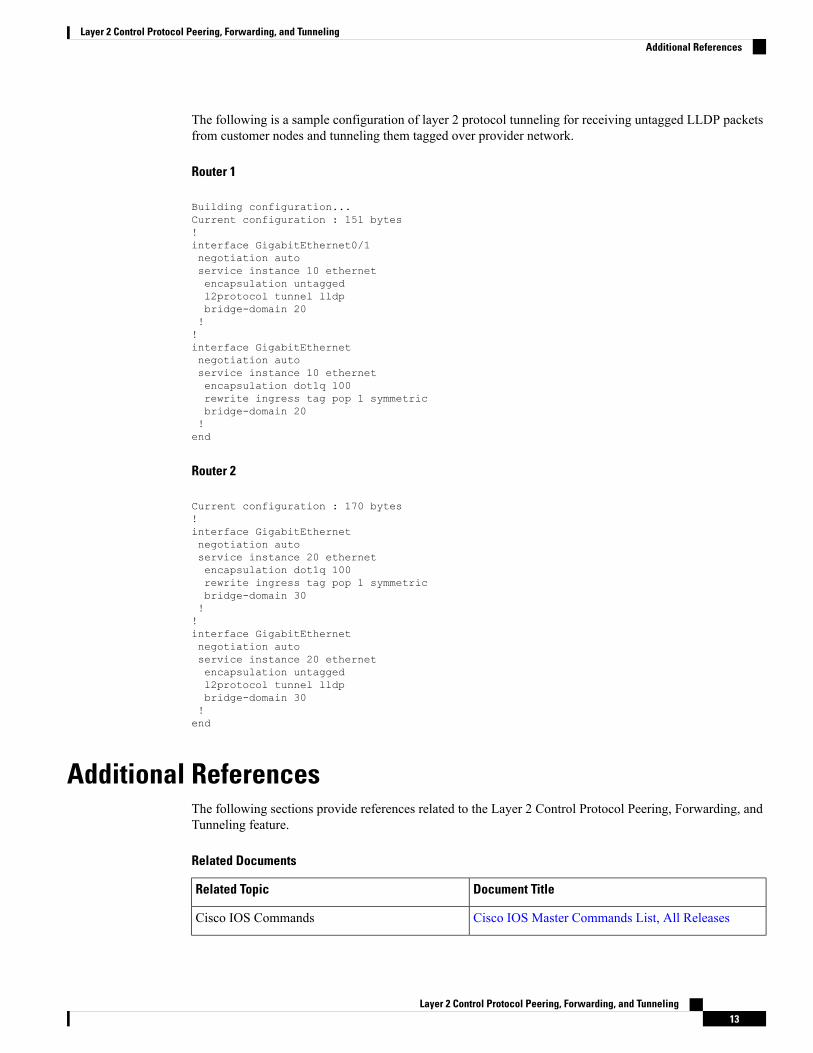
The following is a sample configuration of layer 2 protocol tunneling for receiving untagged LLDP packetsfrom customer nodes and tunneling them tagged over provider network.
Router 1
Building configuration...Current configuration : 151 bytes!interface GigabitEthernet0/1negotiation autoservice instance 10 ethernetencapsulation untaggedl2protocol tunnel lldpbridge-domain 20!!interface GigabitEthernetnegotiation autoservice instance 10 ethernetencapsulation dot1q 100rewrite ingress tag pop 1 symmetricbridge-domain 20!end
Router 2
Current configuration : 170 bytes!interface GigabitEthernetnegotiation autoservice instance 20 ethernetencapsulation dot1q 100rewrite ingress tag pop 1 symmetricbridge-domain 30!!interface GigabitEthernetnegotiation autoservice instance 20 ethernetencapsulation untaggedl2protocol tunnel lldpbridge-domain 30!end
Additional ReferencesThe following sections provide references related to the Layer 2 Control Protocol Peering, Forwarding, andTunneling feature.
Related Documents
Document TitleRelated Topic
Cisco IOS Master Commands List, All ReleasesCisco IOS Commands
Layer 2 Control Protocol Peering, Forwarding, and Tunneling13
Layer 2 Control Protocol Peering, Forwarding, and TunnelingAdditional References
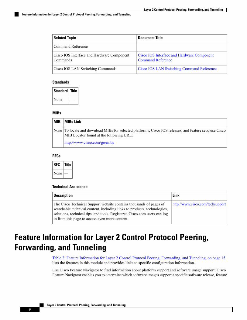
Document TitleRelated Topic
Command Reference
Cisco IOS Interface and Hardware ComponentCommand Reference
Cisco IOS Interface and Hardware ComponentCommands
Cisco IOS LAN Switching Command ReferenceCisco IOS LAN Switching Commands
Standards
TitleStandard
—None
MIBs
MIBs LinkMIB
To locate and download MIBs for selected platforms, Cisco IOS releases, and feature sets, use CiscoMIB Locator found at the following URL:
http://www.cisco.com/go/mibs
None
RFCs
TitleRFC
—None
Technical Assistance
LinkDescription
http://www.cisco.com/techsupportThe Cisco Technical Support website contains thousands of pages ofsearchable technical content, including links to products, technologies,solutions, technical tips, and tools. Registered Cisco.com users can login from this page to access even more content.
Feature Information for Layer 2 Control Protocol Peering,Forwarding, and Tunneling
Table 2: Feature Information for Layer 2 Control Protocol Peering, Forwarding, and Tunneling, on page 15lists the features in this module and provides links to specific configuration information.
Use Cisco Feature Navigator to find information about platform support and software image support. CiscoFeature Navigator enables you to determine which software images support a specific software release, feature
Layer 2 Control Protocol Peering, Forwarding, and Tunneling14
Layer 2 Control Protocol Peering, Forwarding, and TunnelingFeature Information for Layer 2 Control Protocol Peering, Forwarding, and Tunneling
set, or platform. To access Cisco Feature Navigator, go to http://www.cisco.com/go/cfn . An account onCisco.com is not required.
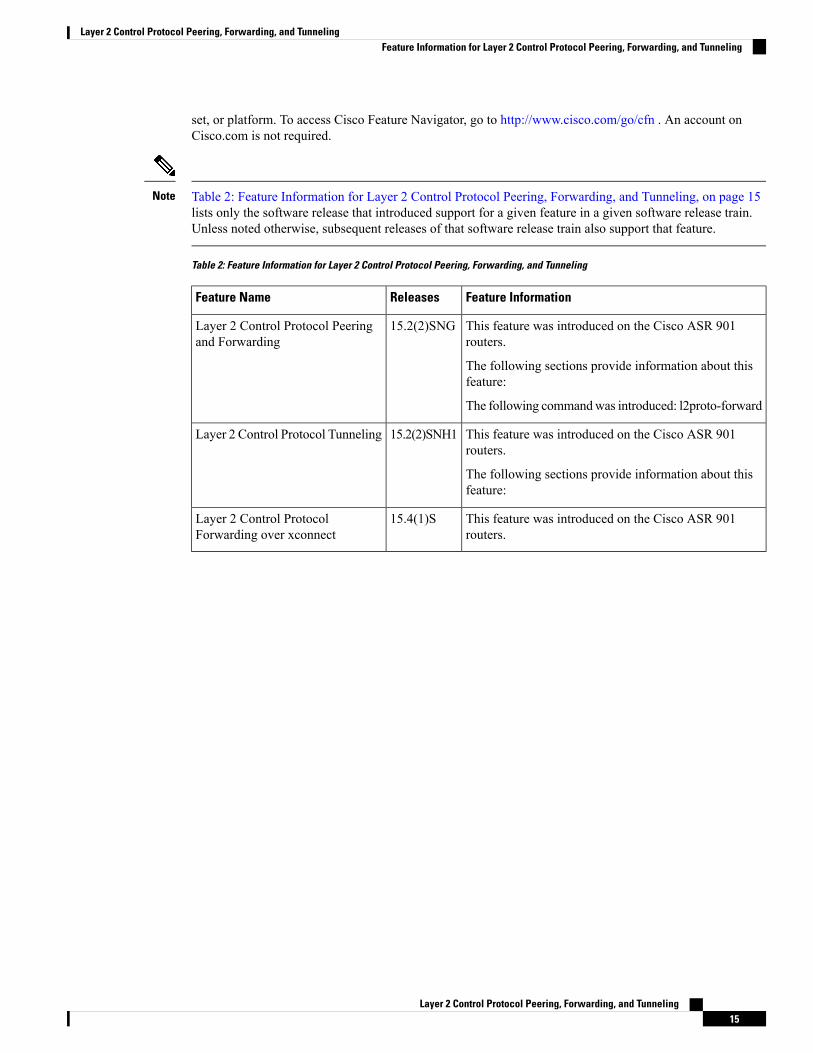
Table 2: Feature Information for Layer 2 Control Protocol Peering, Forwarding, and Tunneling, on page 15lists only the software release that introduced support for a given feature in a given software release train.Unless noted otherwise, subsequent releases of that software release train also support that feature.
Note
Table 2: Feature Information for Layer 2 Control Protocol Peering, Forwarding, and Tunneling
Feature InformationReleasesFeature Name
This feature was introduced on the Cisco ASR 901routers.
The following sections provide information about thisfeature:
The following commandwas introduced: l2proto-forward
15.2(2)SNGLayer 2 Control Protocol Peeringand Forwarding
This feature was introduced on the Cisco ASR 901routers.
The following sections provide information about thisfeature:
15.2(2)SNH1Layer 2 Control Protocol Tunneling
This feature was introduced on the Cisco ASR 901routers.
15.4(1)SLayer 2 Control ProtocolForwarding over xconnect
Layer 2 Control Protocol Peering, Forwarding, and Tunneling15
Layer 2 Control Protocol Peering, Forwarding, and TunnelingFeature Information for Layer 2 Control Protocol Peering, Forwarding, and Tunneling

Layer 2 Control Protocol Peering, Forwarding, and Tunneling16
Layer 2 Control Protocol Peering, Forwarding, and TunnelingFeature Information for Layer 2 Control Protocol Peering, Forwarding, and Tunneling