Embed Size (px)
Citation preview

June 1, 2000 UAF CAD Standards
University of Alaska FairbanksFacilities Services
Division of Design and Construction
CAD STANDARDS
June 1, 2000

June 1, 2000 UAF CAD Standards
University of Alaska FairbanksFacilities Services
Division of Design and Construction
CAD StandardsJune 1, 2000
Table of Contents
PART 1: Working With the CAD Standards
Section 1. Purpose and scope of the CAD standards
1.1 Why the University has data standards1.2 Scope of the CAD standards1.3 Who must use the standards?
Section 2. CAD Environment
2.1 Basic CAD Software2.2 CAD Application Software
Section 3. Requesting CAD Data from the University
3.1 How to request data
Section 4. Deliverables required by the University
4.1 CAD drawings4.2 Documentation4.3 Software and software licenses4.4 Submittal schedule4.5 Validation of delivered materials
Section 5. Communication about the CAD data standards
5.1 Suggestions for the standards
PART 2: Technical Requirements for CAD Data

June 1, 2000 UAF CAD Standards
Section 6. Types of CAD files
6.1 Model files6.2 Sheet files6.3 Managing data for enlarged plans
Section 7. CAD file names
7.1 Sheet file names
Section 8. Layers
8.1 Layer Format8.2 Common Layers Used in All Files
Section 9. Drawing Set Up
9.1 Drawing units9.2 Accuracy9.3 Scale9.4 Origins and registration of CAD data files9.5 Entities and graphic representation9.6 Saved state of CAD model files9.7 Sheet sizes, borders, and title blocks9.8 Plotting9.9 Sheet identification/numbering9.10 Title blocks/borders9.11 As-Built and Conformed Stamps
Section 10. Symbology and Composition
10.1 Line types10.2 Line type scale10.3 Line weight and color10.4 Text and Fonts10.5 Annotation10.6 Dimensions10.7 Xref (External Reference) Files10.8 Blocks10.9 Hatching
Section 11. References: Organizational Addresses
Appendix A: Layer Names
PART 1: Working With the CAD Standards
The first part of this manual describes how to conform to these standards: the purpose and scope

June 1, 2000 UAF CAD Standards
of the standards, receipt and delivery of data, and communication. The second part of the manual describes the University's technical requirements for CAD data.
Section 1. Purpose and scope of the CAD data standards
Computer-Aided Design (CAD) is an accepted tool for producing the documentation required for construction and management of facilities; it also provides for a common medium of information exchange. In fact, the true power and potential of CAD is the ability to re-use and share the information contained within the CAD document. The key to realizing this potential is common organizing principlesBstandards for the production and dissemination of CAD information. The standard organization of files, layers and entities, as well as standardized software applications is essential for effective work and communication. Standards are necessary to ensure that:
CAD drawings and data created in one phase (e.g., design) are readily usable in subsequent phases (e.g., facility management).
Drawings and data are applicable for their intended use.
Drawings and data are compatible with the available CAD equipment and software.
Drawings and data created for one project or project discipline, are compatible with those created for others.
Drawings and data can be transferred and integrated with other applications, such as facility management.
Drawings and data created in one department of the University are consistent with those developed by the other departments.
The compatibility of the University CAD drawings and data with pertinent national, international and industry standards is maintained.
Because CAD guidelines relate to an area of technology that continues to change, it is important that they evolve and improve. To ensure that the University of Alaska Fairbanks and its consultants conform to the broader scope of the proposed National CADD Standard, sponsored by the National Institute of Building Sciences (NIBS) CADD Council, these Standards partially incorporate recommended guidelines from the following:
American Institute of Architects (AIA), CAD Layer Guidelines, 1997
The Construction Specifications Institute (CSI), Uniform Drawing System (UDS)
The Tri-Service CADD/GIS Technology Center, symbols and deliverables
GSA PBS National CAD/CIFM Standards

June 1, 2000 UAF CAD Standards
1.1 Why the University has data standards
This CAD data standards manual is part of the University's comprehensive facilities management strategy. Much of the CAD data created for the University of Alaska Fairbanks will be brought into the University's Information Management System, and this data must follow these CAD data standards to be readily useful within that system.
This document sets performance standards for CAD data delivered to the University. The University does not intend to influence the methods or means of practice of outside consultants.
The University is committed, however, to enforcing the standards of information delivery that insure predictability and the ability to easily reuse information. As a result, these standards will be included as part of the contractual requirements for delivery of electronic information to the University of Alaska Fairbanks Division of Design and Construction.
1.2 Scope of the CAD data standards
This data specification covers all construction documents prepared by or on behalf of the University of Alaska Fairbanks. The deliverables described in this manual must be provided for each sheet that is issued for construction in a project and must include all supporting data files that are used to produce the finished sheets.
If additional electronic design drawings or 3D models are provided, it is the responsibility of the consultant to initiate discussion with the University Owner's Representative to determine an acceptable format for those deliverables.
1.3 Who must use the standards?
Anyone who is going to prepare CAD data for the University, including University Facilities Services staff, contractors, and consultants, must read and become familiar with this document before proceeding with any work. (The term "consultant" used in this manual refers to the person or organization who is preparing the CAD data, whether the person or organization is part of the University or not.)
Section 2. CAD Environment
2.1 Basic CAD Software
The designated CAD software for the University is Autodesk's AutoCAD. All CAD drawings are required to be delivered in AutoCAD's .dwg file format.
2.2 CAD Application Software
CAD application software packages operate on top of, or in conjunction with, the basic CAD software to extend its capabilities. The extensions enhance design, drafting and modeling productivity and link non-graphic attribute data to the graphic entities. All CAD application packages used by Facilities Services, or its consultants, which modify or create CAD layers or

June 1, 2000 UAF CAD Standards
other entities must comply with these standards.
Section 3. Requesting CAD Data from the University
Consultants may request copies of existing CAD data for University facilities. CAD data is provided for the convenience of the recipient only. This data has been gathered from a variety of sources, and it may or may not conform to University CAD standards. The data may be incomplete, or may not accurately reflect current facility conditions.
The University makes no representation as to the data's completeness or accuracy. Consultants also should acknowledge that CAD data appears to be extremely accurate because it has been generated with a computer, and that the accurate appearance of drawings does not guarantee that they truly represent existing conditions.
CAD data submitted by consultants to the University must be accurate and must conform to the current CAD standards, even if reference data provided by the University was inaccurate or did not conform to the standards.
3.1 How to request data
Requests should be made to the University's owner representative. The owner representative will review the request and forward it to AutoCAD Support group, who will have the requested files copied and sent to the owner representative.
Section 4. Deliverables required by the University
At the conclusion of a project, there are three types of materials that consultants must submit to the University, as follows:
CAD drawings
Documentation
Software and software licenses, if applicable
Each of these submittals is explained in more detail below.
4.1 CAD drawings
Consultants will deliver to the University a complete set of the project's CAD documents in electronic form. These documents must include all supporting CAD files and must be delivered as follows:
In the currently supported AutoCAD version in use within Division of Design and Construction. Verify the current release with the Owner's Representative. As of
June 1, 2000, AutoCAD R14 is in use within DDC.

June 1, 2000 UAF CAD Standards
On acceptable media
Reflecting "as built" conditions
Using the data structure defined in this manual.
Neutral File Format
CAD graphic files copied to neutral file exchange formats such as drawing exchange format (.dxf) and initial graphics exchange specification (.iges) can be read by numerous basic CAD packages. However, none of the neutral file exchange formats currently available have reliable mechanisms to transfer the wide variety of non-graphic linkage mechanisms used in both basic CAD and advanced CAD application software packages. Therefore, neutral drawing exchange formats are not acceptable.
AutoCAD R14 or current version file format
All files must be delivered in native .DWG file format in a version that can be used by the currently supported version of AutoCAD within FS without conversion. DXF format files are not acceptable. Verify the current release with FS Division of Design and Construction.
Acceptable media for delivery of CAD data
Digital data sets larger that 1.4 (Mb) shall be furnished via compact disc-read only memory (CD-ROM). Files shall be delivered in uncompressed format.
Digital media labels should contain the following information as a minimum:
University project name and number
Building name and number
Short description of media content, ie: As-Builts, Conformed, Bid Documents, Shop Drawings, etc
Consultant name and telephone number
Date of submittal
Virus scanned (date and software used)
Both the CD-ROM case and the CD-ROM itself shall be labeled.
All digital media, which contains files for entry into the University drawing library, must be scanned for viruses. This includes all files received from sources within and outside the University. Reflecting "as built" conditions
The University needs CAD data that reflects the actual condition of its facilities. CAD drawings

June 1, 2000 UAF CAD Standards
submitted by consultants must show "as built" conditions of any facilities affected by a project.
"As built" drawings include design and detail changes that may have taken place after the initial issue of construction documents, as well as changes made to the actual facility during construction.
Conformance to CAD data standards
The CAD data delivered to the University by consultants must comply with the University CAD Standards that are in effect during the current project.
The current project's CAD drawings may contain information that has been extracted from existing University CAD drawings, which may not conform to the current CAD standards. The consultant must make sure that all CAD data delivered with a project conforms to the current CAD data standard, even if the source drawings did not conform.
The consultant will be required to update any non-conforming CAD drawings that are used to produce the current project's drawings.
4.2 Documentation
The delivered CAD drawing files must be accompanied by the documentation described below. This information must cover all CAD files delivered to the University.
A list of any extended discipline codes, non-standard drawing type codes, and user defined codes that are used in the CAD file names.
A list of approved exceptions to the standard layer structure (a single exception list is acceptable if all files conform to the list).
A list of any deviations from the standards, with reference to the written approval obtained for those deviations that required prior approval.
A description of any third party products that have been used with the drawings and reference to written approval for their use. (See also CAD Application Software in the CAD Environment section.). This is necessary if the CAD application software:
affects the University's ability to review or edit the drawings
requires the University to own a license to the software to work with the CAD files without violating the software's copyrights.
4.3 Software and software licenses
The University strongly prefers that the delivered CAD files be usable without any additional software licenses or installation. If additional software (font files, menus, symbol libraries, etc.) will be required, it must be approved by the Owner's Representative prior to its use.

June 1, 2000 UAF CAD Standards
If the CAD files cannot be viewed or edited without additional licensed software, the consultant must provide the University with valid licenses for that software on acceptable delivery media.
4.4 Submittal schedule
The final submittal of "as built" CAD data should be made after project construction is complete and facilities have been occupied.
In addition, the University may require sample submittals at key milestones in the development of the CAD drawings, specifications and data in accordance with the contract.
Sample submittals are not intended to be a burden on the consultant, and typically will involve a very limited number of drawings. It is recommended that digital media submittals, as a minimum, be provided at the first and final submittal milestones. Providing digital media at the first submittal milestone will allow the University to verify that the data structures being used by the consultant conform to the CAD data standards and are readily usable on the University CAD systems.
4.5 Validation of delivered materials
The University of Alaska Fairbanks Division of Design and Construction Department will validate the CAD data and other materials submitted by consultants. If submittals do not conform to the CAD data standards, the University may return the materials to the consultant.
The consultant is responsible for revising the materials to make them conform to the standards.
Section 5. Communication about the CAD Standards
These Cad Standards will be most effective for the University and most usable for consultants if there is communication between consultants and the University Owner's Representative.
Consultants should ask questions about the CAD data standards before beginning work. Direct questions to the Division of Design and Construction, University of Alaska Fairbanks. Concerns regarding the impact of the CAD standards on a particular project must be discussed with the Owner's Representative.
Consultants questions are valuable because they help the University understand the real-world conditions of each project's design and construction process. Questions will raise issues that will result in better CAD standards.
5.1 Suggestions for the standards
The content of the manual is intended to be neither static nor all-inclusive and thus will be updated and enhanced as appropriate. Suggestions for improvements are encouraged so that

June 1, 2000 UAF CAD Standards
subsequent updates reflect the needs of the University. Submit suggestions, as well as any pertinent new information which would enhance these standards, to the Owner's Representative.
PART 2: Technical Requirements for CAD Data
The organization and format of the CAD deliverables should support the requirements of the University project for design, construction, bidding and archiving. The deliverable should also readily support the integration of information into other University management systems, such as facility management systems, with minimal additional effort.
The University's standards for CAD file types, file names, and sheet numbering are based on industry standards. The requirements of these standards are described below.
Section 6. Types of CAD files
The University's CAD data will include two distinct types of CAD files, model files and sheet files.
Model files contain the project's data, and sheet files are the vehicles used to present the data in different ways.
6.1 Model files
A model file contains the graphics, which describes a subset of a building's geometry and its physical components: walls, doors, windows, columns, beams, outlets, ducts, etc. This information can be thought of as a computer "model" of the facilities involved in a project.
A model must be created at real size: 1=1. Most buildings are described by a series of two-dimensional models: plans, elevations, sections, and details.
Model files are usually referenced by other files. Models can contain other models referenced in those files.
6.2 Sheet files
Sheet files are used to assemble model files, title blocks, and other information for plotting. A sheet file contains one or more scaled views of one or more models arranged within a border and title block.
A sheet file is a 'ready-to-plot' CAD file. Each sheet file contains the parameters that will produce its corresponding plotted drawing, such as scale, layer visibility, and graphic appearance. Sheet files contain AutoCAD's paper space information. They are never referenced by other files.
By organizing information into model and sheet files, plans and other drawings can be developed without concern for layout of the construction document. Sheet files can also be
June 1, 2000 UAF CAD Standards
developed later on in the project cycle. Sheet files allow for consistent plotting standards while also allowing different types of plots from the same CAD model.
Multiple sheets can be created using the same model, where each sheet contains a different graphic representation of the model using different plotting parameters. For example, an architectural floor plan and an electrical power plan can be set up simultaneously using the same model file. In this simplified example, there would be four files: two model files and two sheet files.
6.3 Managing data for enlarged plans
Enlarged views (plans, sections) of a portion of the building typically include information that is not shown in the model file for a full floor plan. The additional information may include building components as well as dimensions and annotations. A similar situation may occur when creating alternative design options for the same location in a facility. This standard provides two methods for managing information that is included in enlarged plans or alternate views.
Method 1: Additional layers in the model file
Additional model data and dimension text is added on special layers to the existing model file. These layers will hold text and more details about the model that appear on enlarged plans. The additional data layers can be turned on when the information should appear in a plotted sheet. Text and dimensions should be appropriately sized for the scale of the plotted sheet.
The additional layers must not contain duplications of data that exists in other layers. Layers should be referenced, even by other layers, so that duplicate data is not drawn and does not have to be maintained.
A method for naming these additional layers is described in the section of this manual that covers layers.
Method 2: Separate model files
A separate model file may be created to hold additional model data that appears on some plotted sheets. This model file will hold text and more details about the model that appear on enlarged plans. Only the additional data needed for the enlarged plan should be included in this model.
This model file should be referenced by the sheet file when this additional information is needed.
The additional model files must not contain duplications of data that exists in other model files. Model files should be referenced, even by other model files, so that duplicate data is not drawn and does not have to be maintained.
Either of these methods is acceptable to the University. Generally, it is easier to maintain model data that has been created in multiple model files. It may be easier to work with the data during the design and construction documentation process, however, if there are fewer model files but more layers.

June 1, 2000 UAF CAD Standards
Section 7. CAD file names
The sheet identification format has its roots in traditional construction drawing techniques. CAD files must be named following the "8.3" (eight character file name followed by a three character extension) short file naming convention, where each file name has a maximum of eight characters, a dot, and a three-character extension.
The eight-character file names must follow the naming rules described in this section of the manual. Rules are described for sheet files.
The three-character extension for CAD drawing files must be DWG. The following naming convention is required for sheet file name.
7.1 Sheet file names
The use of systems methods, overlay drafting, and now CAD has demanded more consistency in labeling and organizing sheets. Sheet file names must be constructed in the format in Table 1.
Sheet Number
UAF Project Number Acronym
Discipline Code
Sheet Sequence Number/User Definable
Code
Extension
ABCD- A 01 .DWGTable 1: Sheet file name example
UAF Project Number Acronym
The first four or five characters reflect the specific acronym given to every University project. The hyphen is a required placeholder in the absence of a fifth character.
Discipline code
The sixth character shows the letter that must be used for the first character of the discipline code shown in Table 2.
Code Discipline
A Architectural
C Civil Engineering

June 1, 2000 UAF CAD Standards
E Electrical Engineering
F Fire Protection
G General
H Hazardous Materials
I Interior Design
L Landscape Architecture
M Mechanical Engineering
P Plumbing
S Structural Engineering
T Telecommunications
X Other disciplines
Z Contractor/shop drawingsTable 2: CAD file discipline codes example
Sheet sequence number
The seventh and eighth characters of a sheet number contain the sheet sequence number, which is a two-digit number that starts at 01 and may ascend through 99. The sheet sequence number identifies each sheet in a series of the same discipline and sheet type. As many numbers may be used as are needed for each discipline/sheet type combination.
Sheet numbers must use two digits, even if a project does not require that many sheets. The use of two digits allows sheet file name to be consistent regardless of project size.
Every drawing sheet in a project must be assigned a unique identifying number that appears on the plotted output. There is a one-to-one correspondence between sheet files and plotted sheets in a project.
All sheet types may apply to all disciplines, but it is not necessary to use all sheet types within a project or within a discipline.
Consultants may combine different types of drawings on the same sheet, for simplicity. For instance, it is acceptable to place schedules on a plan sheet where the information is closely associated.On some projects, the presence of split-levels, mezzanines or interstitial spaces may make it difficult to use floor numbers as sheet sequence numbers. Consultants should evaluate the needs of a project when developing the project's sheet sequence numbering scheme.
June 1, 2000 UAF CAD Standards
Many times sheets are added to a project's set of drawings after sheet sequence numbers has been assigned and is in use. These additional drawings may be inserted in the set by using suffixes, which can be in addition to the two user definable characters of the sheet number. The user definable characters are described below.
User definable code
The University recommends that consultants follow the CSI's method of using these characters to indicate when a sheet has been reissued with revised information.
The examples in Table 3 show possible uses for these two characters.
Sheet Number Description
A-01R1 Floor plan sheet A-01, reissued after partial revision
A-01X1 Floor plan sheet A-102, reissued after total revision
A-01A Floor plan sheet for unit A of floor 01 when a facility is large enough that theentire floor plan will not fit on one sheet.
A-01A1 Floor plan sheet A-01A1 for phase 1 of a sequenced construction
Table 3: User definable codes
Consultants may determine the user definable codes that make sense for a project. A list of user definable codes and their meanings must be submitted to the University.
Extension
The University requires that all sheet files be named with the sheet number that appears on the plot, plus the AutoCAD file name extension .DWG.
Section 8. Layers
The University has adopted in part the CAD layer naming system published by the AIA in its 1997 CAD Layer Guidelines. Consultants should follow that layer naming system when additional layer names are required in a project's CAD drawings that are not addressed in the UAF CAD Layering Standard.
Layer names and assignments are shown in Appendix A: UAF CAD Layer Standards. The layer table categorizes layers by discipline and by type of CAD file. This table also shows several items for each layer, as follows:
A complete listing of all layer names
A detailed definition for each layer

June 1, 2000 UAF CAD Standards
The presentation graphics associated with each layer. Some colors and line types are listed as a preference of the University but not a requirement.
Consultants who wish to use additional layers must submit a list of proposed layer names and their meanings to the University.
8.1 Layer Format
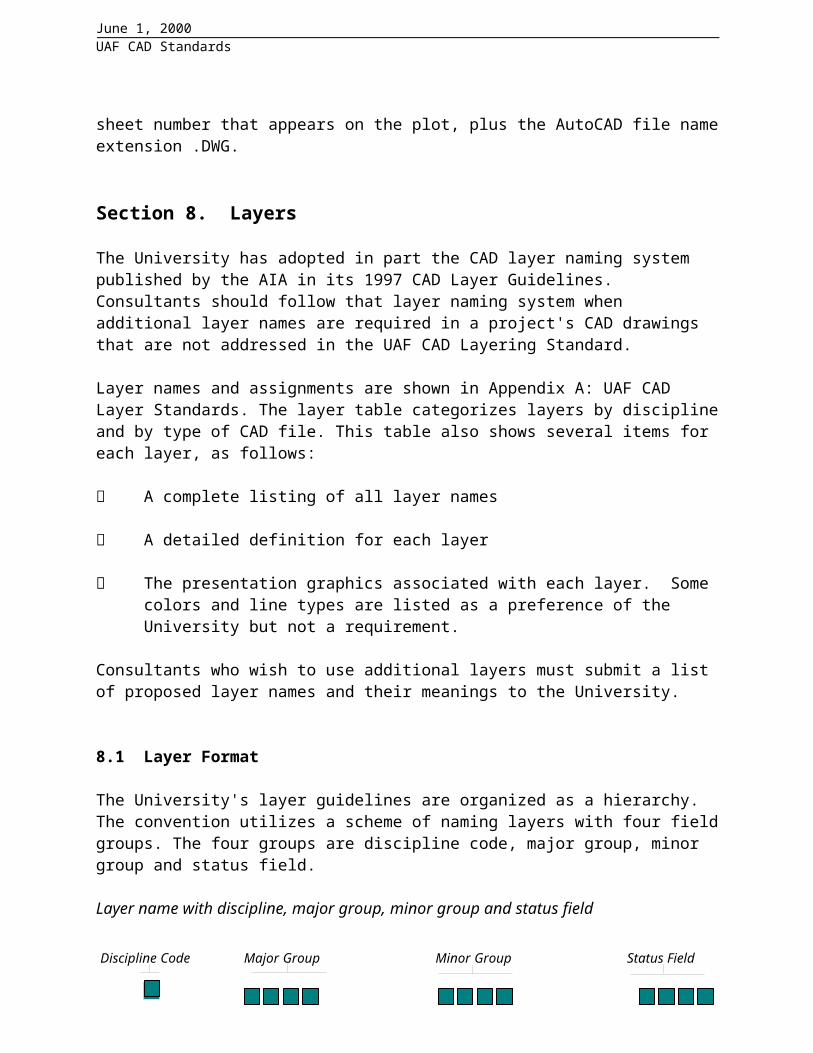
The University's layer guidelines are organized as a hierarchy. The convention utilizes a scheme of naming layers with four field groups. The four groups are discipline code, major group, minor group and status field.
Layer name with discipline, major group, minor group and status field
Discipline Code
The Discipline Code is a one-character field. The defined codes are the same for both layers and file names. Table 2 shows the letters that must be used for the first character of the discipline code.
Major Group
Major groups are a four-character field used to identify the building system. Major groups are typically grouped with specific discipline codes. For example, a drawing might contain the following layers:
A-WALL Walls A-DOOR Doors C-PKNG Parking LotsMinor Group
Minor groups add an additional set of information to the layer names. It is an optional, four-character field that further differentiates major groups into types of information. For example, A-WALL-PART indicates architecture, new, wall, and partial height.
User-Definable Fields
The minor group field can be defined by the user, allowing additional layers to be added to accommodate special project requirements. This should only be done if a defined layer does not apply to a project. Some examples of layers using a user-defined minor group field are as follows:
Discipline Code Major Group Minor Group Status Field

June 1, 2000 UAF CAD Standards
A-DOOR-PRHT Partial height doors
A-WALL-EXT Exterior walls
M-EXHS-DUCT Exhaust system ductwork
E-LITE-EMER Emergency light fixtures
Layer lists are provided in Appendix A.
8.2 Common Layers Used in All Files
Annotation Layers
Annotation comprises of text, dimensions, sheet borders, detail references, and other elements on CAD drawings that do not represent physical aspects of a building. The major group “ANNO” designates annotation. Types of annotation are designated in Table 4 as follows:
Layer Name Layer Description
*-ANNO-DIMS Extension lines, dimension arrowheads/dots/slashes, dimension text
*-ANNO-KEYN Keynotes with associated leader lines and arrowheads, ConDoc keynotes
*-ANNO-LEGN Legends and schedules
*-ANNO-NOTE General notes and general remarks
*-ANNO-NPLT Construction lines, reference targets, area calculations, review comments, viewport windows
*-ANNO-PATT Miscellaneous patterning, cross-hatching, poche'
*-ANNO-REDL Redline
*-ANNO-REVS Revisions
*-ANNO-SYMB Miscellaneous symbols
*-ANNO-TEXT Miscellaneous text and callouts with associated leader lines and arrowheads
*-ANNO-TTLB Border and title block
*ANNO-XREF Reference files
Table 4: Annotation Layers. * asterisk represents discipline code
Annotation can be placed in both model files and in sheet files. Dimensions, symbols, and

June 1, 2000 UAF CAD Standards
keynotes would typically be placed in model files. Borders and title blocks would typically be placed in sheet files. The same layer names would be used in both cases.
A special case exists when a single model file is referenced by two or more sheet files. In this case, it may be necessary to differentiate two or more "sets" of annotation. Consultants should name these layers by adding a hyphen and four characters to the end of any standard major group. For example, a model file containing both floor plan and ceiling plan information may need different layers for ceiling plan dimensions and floor plan dimensions. In this case, users should modify the minor group to indicate the intended view. For example, A-ANNO-DMFP for floor plan dimensions and A-ANNO-DMCP for ceiling plan dimensions. These new layers and the information they contain must be documented and submitted to the University.
Status Layers
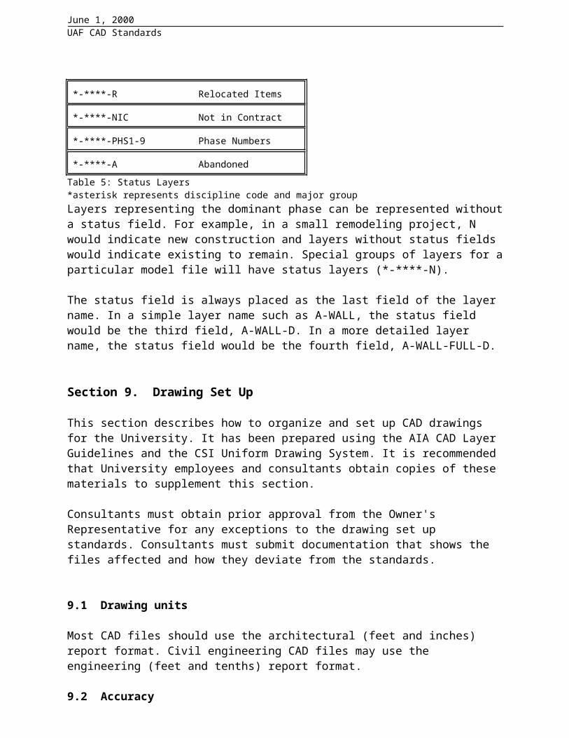
The status field is an optional, four-character field that designates the phase of construction and status of the elements. This field is optional and is only needed when phases of work need to be differentiated. Table 5 shows the defined values for this field:
Layer Name Layer Description
*-****-N New Work
*-****-E Existing to Remain
*-****-D Existing to Demolish
*-****-F Future Work
*-****-T Temporary Work
*-****-M Items to be Moved
*-****-R Relocated Items
*-****-NIC Not in Contract
*-****-PHS1-9 Phase Numbers
*-****-A Abandoned
Table 5: Status Layers*asterisk represents discipline code and major groupLayers representing the dominant phase can be represented without a status field. For example, in a small remodeling project, N would indicate new construction and layers without status fields would indicate existing to remain. Special groups of layers for a particular model file will have status layers (*-****-N).
The status field is always placed as the last field of the layer name. In a simple layer name such as A-WALL, the status field would be the third field, A-WALL-D. In a more detailed layer name, the status field would be the fourth field, A-WALL-FULL-D.

June 1, 2000 UAF CAD Standards
Section 9. Drawing Set Up
This section describes how to organize and set up CAD drawings for the University. It has been prepared using the AIA CAD Layer Guidelines and the CSI Uniform Drawing System. It is recommended that University employees and consultants obtain copies of these materials to supplement this section.
Consultants must obtain prior approval from the Owner's Representative for any exceptions to the drawing set up standards. Consultants must submit documentation that shows the files affected and how they deviate from the standards.
9.1 Drawing units
Most CAD files should use the architectural (feet and inches) report format. Civil engineering CAD files may use the engineering (feet and tenths) report format.
9.2 Accuracy
All CAD drawings shall be drafted using precision input employing the most accurate source material available. For all drawing entities, zero tolerance is required, all lines meet at intersections, straight lines are straight, blocks are inserted properly without overlap, etc.
Consultants are responsible for the accuracy of all CAD drawings delivered to the University, regardless of the accuracy of CAD drawings of previous projects furnished by the University as a convenience to the consultant.
9.3 Scale
Objects shall be created at full size--a 100-foot wall will be drawn to 100 feet and a 36-inch column will be drawn to 36 inches. The following types of CAD drawings may be drawn to any scale: schedules, riser diagrams, schematic diagrams and single line diagrams.
9.4 Origins and registration of CAD data files
The origins of CAD model files must be defined at coordinates 0, 0, 0. This is typically the lower left corner of the building. For non-rectilinear buildings a logical origin point shall be established.
The origin point must remain consistent between all model files in a project. This is critical for correct registration of different model files when referenced together, aligning the various views of the facility. Registration of electronic data must be maintained so the information will be usable in future applications.
The origin of each CAD sheet file should be at the lower left-hand corner of the sheet border and set to coordinates 0, 0, 0.

June 1, 2000 UAF CAD Standards
Special considerations for site plans
Civil Engineering CAD model files may use true geographic coordinates for their origins.
9.5 Entities and graphic representation
Curved Entities
Circles, arcs and ellipses shall be created as individual entities, not of line segments.
Drawing Limits
Drawing and extents must be checked to ensure there are no objects outside the drawing limits. Objects outside the drawing limits will slow the regeneration and manipulation of the drawing. All drawings shall be submitted with the drawing display zoomed to the drawing extents.
Entity Properties
Entity properties such as color and linetype shall be BYLAYER. For purposes of clarity, some symbol and block properties may not be set BYLAYER, but this should be avoided whenever possible.
9.6 Saved state of CAD model files
CAD files should be delivered in the state described below.
Blocks should not be exploded.
Drawings should be purged.
Drawings should be zoomed to extents.
Drawings should be left in paperspace if they use paperspace
The menu should be set to ACAD.
9.7 Sheet sizes, borders, and title blocks
Sheet sizes, borders, and title blocks used for University projects will comply with the Uniform Drawing System (UDS), 1997, drawing sheet standards developed by the Constructions Specifications Institute.
Select American National Standards Institute (ANSI) architectural sheet, regular architectural sheet size or Metric sheet size to best fit the project size and complexity, and unit of measurement (Metric or English). Consider also plotter limitations and handling/storage of hard copies.
Determine if the selected sheet size has been specified by the Owner's Representative before
June 1, 2000 UAF CAD Standards
starting the project.
9.8 Plotting
Each sheet drawing file generally represents a single plotted drawing. The sheet origin point is the lower left-hand corner of the sheet. The sheet border may be an xref file inserted at 0,0. No drawing entities should reside outside of the sheet's border. When saving a sheet file, make only the layers needed for correct plotting of the sheet visible. Plotting shall be set at a scale of 1"=1".
9.9 Sheet identification/numbering
Sheet sequence identifier numbers start at 01 and continue through to 99. Sheet numbering systems vary and shall be approved before beginning the drawing set. The CSI UDS guidelines shall be used unless an exception is approved by the Owner's Representative (see also the section on Sheet file names).
9.10 Title blocks/borders
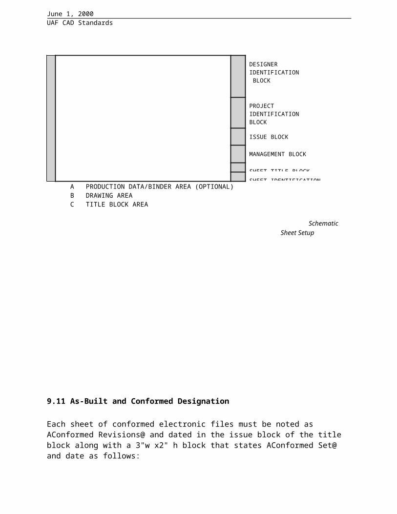
Title blocks and borders shall follow CSI Uniform Drawing System (UDS) guidelines unless an exemption is approved by the Owner's Representative. A sample title block layout and schematic sheet setup follows. Refer to the UDS for additional guidance.
Title Block AreaBased on CSI Uniform Drawing System
Key plan block if used. (Or, key plan may be placed in lowest module of note block.)
KEY BLOCK PLAN (IF USED)
Identifies designer or preparer of sheet. Include: NameAddressTelephone/Fax NumberE-mail/InternetBlock may also include preparer's logo, professional seals, certifications and the name and addresses of consultants
DESIGNERINFORMATIONBLOCK
Identifies the project. Includes: Project name, number and addressBuilding/Facility name and numberConstruction phase sequenceOwner/Client address,telephone/fax numbers and logo may also be included.
PROJECTIDENTIFICATIONBLOCK
Shows the issue and revision dates. Include mark, date and description columns.
ISSUE BLOCK
Project management information such as project number, drawn/checked by, copyright.
MANAGEMENT BLOCK

June 1, 2000 UAF CAD Standards
Indicates type of information presented on sheet. SHEET TITLE BLOCK
Sheet numberSheet sequence number
SHEET IDENTIFICATION BLOCK
Sample Title Block Layout
OVERALL SHEET LAYOUT SCHEMATICBASED ON CSI UNIFORM/ DRAWING SYSTEM A B
CKEY PLAN BLOCK
DESIGNERIDENTIFICATION BLOCK
PROJECTIDENTIFICATIONBLOCK
ISSUE BLOCK
MANAGEMENT BLOCK
SHEET TITLE BLOCKSHEET IDENTIFICATION BLOCK
A PRODUCTION DATA/BINDER AREA (OPTIONAL)B DRAWING AREAC TITLE BLOCK AREA
Schematic Sheet Setup
9.11 As-Built and Conformed Designation

June 1, 2000 UAF CAD Standards
Each sheet of conformed electronic files must be noted as AConformed Revisions@ and dated in the issue block of the title block along with a 3"w x2" h block that states AConformed Set@ and date as follows:
Stamp must be located in the lower right corner of the drawing area to the left of the title block above a blank space 3"w x 2@h left blank for the successive As-Built stamp block As-Built stamp is to be 3"w x 2"h that states AAS-BUILT@ on top line followed by three lines for the company name, date and signature of authorized representative as follows:
Section 10. Symbology and Composition
10.1 Line types
Use standard linetypes whenever possible. Contour lines, dashed lines and other fonted lines shall be made of one continuous line segment, not a series of separate line segments. If the consultant is using pre-approved basic CAD software other than AutoCAD, insure that linetypes translate correctly in the .dwg file.
Polylines with increased width may be used only to depict non-building drawing elements such as cut-lines. Use of toned or pochéd lineweights for use with inkjet or electrostatic plotters to differentiate new or existing work is acceptable.
Line types that are not AutoCAD defaults must be provided to the University including any software, software licenses, and documentation needed for University staff to use the CAD data without violation of software copyrights.
CONFORMED SET
00/00/00
AS-BUILT
____________________________________Company ____________________________________Date____________________________________Signed

June 1, 2000 UAF CAD Standards
10.2 Line type scale
Line type scale must be set so that each line type is recognizable, easily identified, and distinguishable to individuals who are working in the model files and in final plotted output.
10.3 Line weight and color
Consultants may use additional line weights as needed for effective communication of the project data.
Line weight and color affect the usability of CAD data in different ways. Line weight typically is most useful when working with plotted CAD drawings. Plots, or reproductions of plots, are usually monochrome and the thickness of lines is an important means of communicating information about the facility and the design.
Color is most useful when working with CAD data on a computer screen. Colors allow users to readily identify systems and types of information. On a computer screen, line weight often gets in the way of effective communication.
10.4 Text and Fonts
All text on University CAD drawings shall use only standard text fonts supplied with AutoCAD's font library. CAD files submitted shall be plottable without modification and with no additional software required.
Test size must be legible and appropriate to the graphic information presented and the intended plotted scale of the drawing. Text must be in all upper case letters throughout a drawing, except for electrical switch legs and symbols which require lower case letters.
Text placement guidelines
Text usually should not touch other graphic objects, and must be placed with enough space around it to be legible when the drawing is plotted and reproduced.
Text may be placed at an angle. It must be readable from the bottom or right edges of the plotted sheet. Generally text should be placed at an angle of 0 or 90. Text may be placed along (above or below) another element at an angle other than 0 or 90.
Units
English (Architectural in AutoCAD) units shall be the standard system of measurement. The base unit shall be inches.
10.5 Annotation
Annotation can be placed in either model files or sheet files. Annotations related to model data, such as dimensions, notes, and callouts must be included in the model file where they are easier to coordinate and revise.
June 1, 2000 UAF CAD Standards
Other annotations, such as drawing titles, legends, and sheet-specific notes, are more convenient to work with when placed in the sheet file.
10.6 Dimensions
The default settings for AutoCAD's dimvars should be used. Associative dimensions should be used.
Consultants should insure that all dimensions are in a named dimension style for all dimensions in CAD files, so the dimension parameters can be readily modified as needed.
10.7 Xref (External Reference) Files
Xrefs may be used to subdivide a large CAD drawing into several smaller, more efficient drawings. The use of this procedure will reduce drawing size, increase performance, improve operator efficiency and make coordination of disciplines easier. Xrefs may also be used to split a drawing by disciplines. When possible, avoid nested xrefs. There shall be no specific drive or directory references associated with the xrefs. All xrefs must reside in the same directory as the drawing files.
Consultants must provide all xrefs to the FS Owner's Representative by either separate model files or by Abinding@ the xref (model) files to the sheet file.
10.8 Blocks
Any graphic entity that occurs repeatedly in drawings should be made into a block. Insertion points for blocks shall be consistent with its placement in the drawing. Use a logical insertion point (center of circle, bottom left corner of object, etc.). Keep names simple and descriptive. AutoCAD block names must be unique within each project.
Nested blocks contain more than one block definition. Nested blocks are permitted but should be avoided whenever possible.
10.9 Hatching
Do not use polylines with increased width as a replacement for poché or hatching. Use pattern hatching sparingly since the practice significantly increases the AutoCAD entity count of a drawing (if using versions prior to AutoCAD Release 14).
Section 11. Reference: Organizational Addresses
CAD Layer GuidelinesAmerican Institute of Architects1735 New York Avenue, NWWashington, DC 20006-5292Voice: (202) 626-7300

June 1, 2000 UAF CAD Standards
Orders: (800) 365-2724Fax: (802) 864-7626Email: [email protected]: http://www.aia.org
Uniform Drawing SystemThe Construction Specifications Institute601 Madison StreetAlexandria, VA 22314-1791Voice: (800) 689-2900Fax: (703) 684-0465Email: [email protected]: http://www.csinet.org
Metric Guide for Federal Construction, National CADD StandardNational Institute of Building Sciences (NIBS)1201 L Street NW, Suite 400Washington, DC 20005-4025Voice: (202) 289-7800Fax: (202) 289-1092Email: [email protected]: http://www.nibs.org
Tri-Service CADD/GIS Technology CenterWaterways Experiment Station, Corps of Engineers3909 Halls Ferry RoadVicksburg, MS 39180-6199Voice: (601) 634-4109
(800) 522-6937, ext. 4109Email: [email protected]: http://tsc.wes.army.mil
National CADD Plotting StandardsU.S. Coast Guard Civil Engineering Technology Center1240 East 9th Street, Room 2195Cleveland, OH 44199-2060Voice: (216) 902-6210Email: [email protected]: http://www.cgcetc.org/index.htm
Appendix A: CAD Layer Names
UAF CAD LAYER STANDARD
GENERAL LAYER STANDARD NAMESLAYER NAME LAYER DESCRIPTION COLOR LINETYPE
G-ACCS Access Plan

June 1, 2000 UAF CAD Standards
G-ANNO-NPLT Construction lines, reference targets, View ports.G-ANNO-TTLB General border and title block line workG-ANNO-TXT General border text, notes, and drawing titles, Miscellaneous
text and callouts with associated leader lines and arrowheads.G-ANNO-XREF Reference FilesG-CODE Code compliance planG-EVAC Evacuation planG-FIRE Fire protection planG-INFO General information related to drawings.G-INFO-KPLN Drawing key plan.G-INFO-NODE Drawing nodes.G-PLAN Floor plan-key planG-SITE Site Plan-key map
CIVIL LAYER STANDARD NAMESC-BLDG Proposed building footprint, existing buildings, satellite dishesC-COMM Site communication/telephone poles, boxes, towers, satellite
dishes.C-COMM-OVHD Overhead communication linesC-COMM-UNDR Underground communication linesC-FIRE Fire protection-hydrants, connectionsC-FIRE-UNDR Fire protection-underground linesC-NGAS Natural gas-manholes, meters, storage tanksC-NGAS-UNDER
Natural gas-underground lines
C-PKNG Parking lot information.C-PKNG-CURB Curbs, gutters, etc.C-PKNG-DRAN Parking lot drainage slope indicationsC-PKNG-ISLD Parking islandsC-PKNG-JOIN Control joints.C-PKNG-STRP Parking lot striping, handicap symbolC-PKNG-STRU Parking structures (benches, shelters, headbolt rails, etc.).C-PKNG-SURF Parking lot surfaces.C-PKNG-TEXT Snow removal & general information not related to specific
items.C-PROP Property lines, survey benchmarksC-PROP-BRNG Bearings and distance labelsC-PROP-CONS Construction controlsC-PROP-ESMT Easement, rights-of-way, setback linesC-ROAD RoadwaysC-ROAD-CNTR Center linesC-ROAD-CURB Curbs, gutters, etc.C-ROAD-JOIN Control joints.C-ROAD-STRP Road markings (striping, crosswalks, etc.).C-ROAD-SURF Road surfaces, road base, etc.C-ROAD-SWLK Sidewalks, stairs, bike paths, etc.

June 1, 2000 UAF CAD Standards
C-ROAD-TEXT Snow removal & general information not related to specific items.
C-SITE-FNC FencesC-SITE-TRL Ski TrailsC-SITE-UTIL Utilidors & general utilities (specifics under their discipline)C-SSWR Sanitary sewer-manholes, pumping stationsC-SSWR-UNDR Sanitary sewer-underground linesC-STRM Storm drainage catch basins, manholesC-STRM-UNDR Storm drainage pipe-undergroundC-TEXT General civil notes & text not related to specific items.C-TOPO Topological features, elevationsC-TOPO-BORE Test boring locations, bore logsC-TOPO-LN Contour LinesC-TOPO-RTWL Retaining wallC-TOPO-SPOT Spot elevationsC-TOPO-TXT Elevation TextC-WATR Domestic water-manholes, pumping stations, storage tanksC-WATR-UNDR Domestic water-underground linesARCHITECTURAL LAYER STANDARD NAMESA-AREA-PATT Area cross hatchingA-CLNG Ceiling features.A-CLNG-ACCS Ceiling accessA-CLNG-FIN Ceiling panels, finishes, etc.A-CLNG-GRID Ceiling grid.A-CLNG-IDEN Ceiling identification.A-CLNG-PENE Ceiling system penetrations.A-CLNG-STRU Ceiling support structure/elements, ie: astronomy domes,
clerestories253
A-CLNG-SUSP Suspended elements, soffits, cable traysA-CLNG-TEES Main teesA-CLNG-TXT General notes & text not specifically linked to an item.A-DETL DetailsA-DETL-IDEN Component identifications numbersA-DETL-MBND Material beyond section cutA-DETL-MCUT Material cut by sectionA-DETL-PATT Textures and hatch patternsA-DOOR Doors & door features. 2A-DOOR-FULL Full height (to ceiling) doors.A-DOOR-IDEN Door numbers, hardware groups, etc.A-DOOR-KEY Key & lock core information.A-DOOR-KEYE Electric locking device information (key switches, electric strike
plates, etc).A-DOOR-MOVE Folding door type partitions and curtains.A-DOOR-OH Overhead doors, garage doors

June 1, 2000 UAF CAD Standards
A-DOOR-PRHT Partial height doors.A-DOOR-TXT General notes & text concerning doors not specifically linked to
an item.A-EQPM Equipment.A-EQPM-ACCS Equipment access & maintenance areas (laydown areas).A-EQPM-APPL Fixed appliances. 171A-EQPM-CLNG Ceiling-mounted or suspended equipmentA-EQPM-ELEV Equipment surfaces: 3D viewsA-EQPM-FIXD Fixed equipmentA-EQPM-IDEN Equipment identification.A-EQPM-MOVE Movable equipment and appliances. 181A-EQPM-NIC Equipment not in contractA-EQPM-TXT General notes & text not specifically linked to an item.A-FLOR Floor features.A-FLOR-CASE Casework (manufactured cabinets)A-FLOR-CATW Catwalks, raised platforms, etc. 251A-FLOR-EVTR Elevator cars, equipment, signage devices, etc. 5A-FLOR-FIN Floor covering/finish information.A-FLOR-FIXT Miscellaneous fixtures 21A-FLOR-HRAL Handrails and guardrails. 251A-FLOR-LEVL Changes in floor level, ie: ramps, depressions, pits, stages,
equipment pedestals..A-FLOR-OTLN Floor or building outlineA-FLOR-OVHD Overhead items (skylights, overhangs-usually dashed line)A-FLOR-PATT Paving, tile, carpet patternsA-FLOR-RAIS Raised floor systems.A-FLOR-RISR Stair risersA-FLOR-SPCL Special architectural features, ie: mezzanines, floor hatch doors 6 or 252A-FLOR-STREX Exterior stairs, landings, loading docks, retaining walls, ramps 252A-FLOR-STRS Interior stairs, ladders, escalators.A-FLOR-TXT General notes & text not specifically linked to an item.A-FURN Furnishings.A-FURN-CHAR Chairs and other seatingA-FURN-CURT Windows curtains, blinds, etc.A-FURN-ELEV Furniture: 3D viewsA-FURN-FILE File cabinetsA-FURN-FIX Fixed furnishings (cabinets, casework, lab benches, display
cases, bleachers, auditorium seating, etc.)21
A-FURN-FIX2 Upper Cabinets 21 hiddenA-FURN-MOVE Movable furnishings.A-FURN-PATT Finish patternsA-FURN-PLNT Plants.A-FURN-PNLS Furniture system panelsA-FURN-POWR Furniture system-power designations
June 1, 2000 UAF CAD Standards
A-FURN-STOR Furniture system storage componentsA-FURN-TXT General notes & text not specifically linked to an item.A-FURN-WKSF Furniture system work surface componentsA-GLAZ Window features. 2A-GLAZ- ELEV Glazing and mullions-elevation viewsA-GLAZ-BLOC Glass block partitions and windows.A-GLAZ-FULL Full height glazed walls and partitions.A-GLAZ-HNG Hinge designations of windows 252 hiddenA-GLAZ-IDEN Window numbers and identification.A-GLAZ-PRHT Windows and partial height glazed walls.A-GLAZ-SILL WindowsillsA-GLAZ-TXT General notes & text concerning windows not specifically linked
to an item.A-IDEN Signage.A-IDEN-EXT Exterior signage.A-IDEN-INT Interior signage.A-INV Inventory information.A-INV-AREA Room area delimiters.A-INV-DIV Divisions of spaces not separated by physical wall 1 dashedA-INV-OWNR Room assignment information (operating unit, point-of-contact,
etc.)A-INV-PART Movable partitions defining separate spaces 5 hiddenA-INV-RMID Square feet, assigned user, room type text 4A-INV-RMNO Room numbers. 4A-INV-TXT General notes & text not specifically linked to an item.A-ROOF Roof features.A-ROOF-ELEV Roof surfaces: 3d viewsA-ROOF-EQUIP Roof equipment (antennas, compressors)A-ROOF-FIN Roof surfaces/finishes.A-ROOF-IDEN Roof identification.A-ROOF-LEVL Roof level changes.A-ROOF-OTLN Roof outline. 251 dashedA-ROOF-PATT Roof surface patterns, hatchingA-ROOF-PENE Roof penetrations.A-ROOF-TXT General notes & text not specifically linked to an item.A-SECT SectionsA-SECT-IDEN Component identifications numbersA-SECT-MBND Material beyond section cutA-SECT-MCUT Material cut by sectionA-SECT-PATT Textures and hatch patternsA-WALL Architectural walls.A-WALL-EXT External Walls. 3A-WALL-INT Interior partition walls (full height). 4A-WALL-INTP Interior partition walls (partial height). 4

June 1, 2000 UAF CAD Standards
A-WALL-MOVE Movable partition walls.A-WALL-PEN Interior animal pens, corrals, etc. 150A-WALL-SPCL Fenced walls, security gates, pass-through 252A-WALL-TPTN Toilet room partitions. 252A-WALL-TXT General notes & text concerning walls not specifically linked to
an item.STRUCTURAL LAYER STANDARD NAMESS-ABLT Anchor bolts.S-BEAM Beams, girts, etc.S-COLS Columns. 5S-DECK Structural floor deckS-FNDN Foundation.S-FNDN-INSL Foundation insulation & damp-proofing.S-FNDN-PILE Piles and drilled piers.S-FNDN-RBAR Foundation reinforcement.S-FNDN-REFG Refrigerated pile features. (Active equipment shown on M-
REFG.)S-FNDN-TXT General notes & text not specifically linked to an item.S-FNDN-WALL Foundation walls. 252S-FRAM Frames.S-GRID Building grid lines.S-GRID-EXT Grid lines outside of building perimeter. Includes tags.S-GRID-INT Grid lines inside building perimeter.S-IDEN Structural frame identification.S-JOIS Joists.S-METL Misc. structural members.S-SLAB Slabs.S-SLAB-EDGE Edge of slab.S-SLAB-JOIN Control joints.S-SLAB-RBAR Slab reinforcement.S-SLAB-TXT General notes, slab identification, & text not specifically linked
to an item.S-TXT General notes & text not specifically linked to an item.S-WALL Structural bearing and shear walls.MECHANICAL LAYER STANDARD NAMESM-BRIN Specialized brine circulating systems. Not used for glycol
systems.M-BRIN-EQP Brine system equipment.M-BRIN-PIPE Brine system piping.M-BRIN-TXT General notes & text not related to a specific item.M-CHIM Combustion stacks & chimneys.M-CONT Control system devices, schematics, diagrams, etc.M-CONT-DEV Control system device locations (on layout drawings). White
M-CONT-DIA Control system schematics, schedules, & diagrams. White
June 1, 2000 UAF CAD Standards
M-CONT-TXT General notes & text not related to a specific item. WhiteM-CWTR Circulating cooling systems (chilled water & glycol based).M-CWTR-EQPM Heat exchangers, pumps, etc. 230M-CWTR-FLO Circulating heating system flow (balancing) information.M-CWTR-PIPE Circulating cooling water system piping, valves, etc. 211M-CWTR-TXT General notes & text not related to a specific item. 171M-EXHS Exhaust system equipment & ducting. 252M-EXHS-DIF Exhaust system grilles, inlets, fume & grease hoods, etc.)M-EXHS-DUCT Exhaust system ductwork. 101M-EXHS-EQPM Exhaust system equipment. 101M-EXHS-FLO Exhaust system flow (balancing) information. 101M-EXHS-TXT General notes & text not related to a specific item. 101M-FUEL Fuel oil and special fuel systems.M-FUEL-EQPM Fuel oil system equipment (show burners layer with assoc.
equip.).M-FUEL-PIPE Fuel oil & special fuel piping.M-FUEL-SPL Special system equipment (waste oil, etc.)M-FUEL-TXT General notes & text not related to a specific item.M-HVAC Fan system equipment & ducting. 4M-HVAC-DUCT HVAC ductwork (OA, RA, SA, fire & smoke dampers, etc.). 4M-HVAC-EQPM Fan system (fans, plenums, dampers, fan coils, etc.)
equipment.4
M-HVAC-FLO HVAC system flow (balancing) information. 4M-HVAC-RDFF HVAC return air diffusers, transfer grilles, etc. 4M-HVAC-SDFF HVAC supply air diffusers. 4M-HVAC-TERM HVAC terminal equipment (VAV boxes, dual-duct boxes, CUHs,
etc.)4
M-HVAC-TXT General notes & text not related to a specific item. 21M-HOTW Circulating heating systems (hot water & glycol based).M-HOTW-EQPM Heat exhangers, pumps, boilers, etc. 4M-HOTW-FIN Baseboard, finned-tube, UHs, etc. 212M-HOTW-FLO Circulating heating system flow (balancing) information. 212M-HOTW-PIPE Circulating heating water system piping, valves, etc. 110M-HOTW-TXT General notes & text not related to a specific item. 212M-REFG Refrigeration equipment and systems.M-REFG-EQPM Refrigeration equipment (chillers, unit coolers, split system,
ACCs, etc.).M-REFG-FLO Refrigeration system flow (balancing) information.M-REFG-PIPE Refrigerant piping, tower piping, valves, etc.M-REFG-TWR Circulating heat rejection equipment (cooling towers, dry-
coolers,etc.).M-REFG-TXT General notes & text not related to a specific item.M-STEM Steam system equipment and piping.M-STEM-EQPM Heat exchangers, condensate return stations, PRV stations,
etc.4

June 1, 2000 UAF CAD Standards
M-STEM-FLO Steam system flow (balancing) information.M-STEM-PIPE Condensate, LP, IP, & HP steam piping, valves, traps, etc. 10M-STEM-TXT General notes & text not related to a specific item. 21M-TEXT General mechanical notes & text not assoc. with specific
items.ELECTRICAL LAYER STANDARD NAMESE-ALRM Miscellaneous alarm systemE-CLOK Clock systemE-COMM Communications and computer network information.E-COMM-CIRC Communication/network circuits.E-COMM-DIA Communication/network riser diagrams.E-COMM-IDEN Communication/network equipment identification.E-COMM-OTLT Communications and network connection points/outlets.E-COMM-PANL Communication/computer panels, switchgear, etc. 121E-COMM-RACE Communication/network raceways (conduit, cable trays, etc.).E-COMM-TXT General notes & text not specifically linked to an item.E-CTRL Electrical control separate from bldg mgt system.E-CTRL-DEVC Electrical control device locations (occ. sensors, strike plates,
etc.).E-CTRL-WIRE Control system wiringE-CTRL-DIA Electrical control schematics, diagrams, etc.E-CTRL-TXT General notes & text not specifically linked to an item.E-GRND Grounding.E-GRND-CIRC Grounding system circuits.E-GRND-DIAG Ground system diagramE-GRND-EQUI Equipotential ground systemE-GRND-REFR Referencing grounding system.E-GRND-TXT General notes & text not specifically linked to an item.E-LEGN Legend of symbolsE-LITE Lighting fixtures, switching, circuits, etc.E-LITE-CIRC Normal lighting circuits including switching, occ sensors, photo
cells, contactor5
E-LITE-CIRE Emergency and exit lighting circuits. 1E-LITE-CLNG Ceiling mounted fixtures. 7E-LITE-DLMP Fixture present, lamps removed. 1 line=1 lamp removed 110 dashedE-LITE-EMER Emergency light fixtures (all mounting locations). 1E-LITE-EXIT Exit lights. 94E-LITE-FLOR Floor mounted fixtures.E-LITE-IDEN Fixture identification. 120E-LITE-LEVL Current, as found/as left, light levels in fc's 80E-LITE-NITE Lights on 24 hours a day 4E-LITE-SITE Exterior area/security lighting, street/parking lighting (pole,
pedestal, etc.)E-LITE-SPCL Special light fixtures.E-LITE-TXT General notes & text not specifically linked to an item. 7

June 1, 2000 UAF CAD Standards
E-LITE-WALL Wall mounted fixtures (both interior & exterior).E-LTNG Lightning protection systemE-POWR Electrical power features.E-POWR-CIRC Normal power distribution circuits. 1E-POWR-CIRE Emergency power circuits, uninterrupted power sourceE-POWR-DIA Power and lighting riser diagram.E-POWR-IDEN Electrical power equipment identification.E-POWR-OTLT Power outlets (wall receptacles, multi-outlet floor boxes, etc.). 120E-POWR-PANL Power panels, switchgear, load centers, transformers. 5E-POWR-RACE Power raceways (conduit, busduct, cable trays, j-boxes, etc.).E-POWR-SITE Site power distribution/transmission (overhead & underground).E-POWR-TXT General notes & text not specifically linked to an item.E-SEC SecurityE-SEC-MD Motion Detectors 5PLUMBING LAYER STANDARD NAMESP-GWTR Gray (non-potable) water system piping and equipment.P-GWTR-FIXT Gray water fixtures.P-GWTR-PIPE Gray water piping, valves, etc.P-GWTR-TXT General notes & text not related to a specific item.P-LAB Air, vacuum, specialized lab gas, etc. systems.P-LAB-AIR Compressed air piping & equipment for labs, controls, process,
etc.P-LAB-GAS Natural gas & specialized lab gases equipment & piping.P-LAB-LPG Lab, process, & fuel propane (& other LPGs) equipment &
piping.P-LAB-SPL Lab & process acids, bases, etc. equipment & piping.P-LAB-TXT General notes & text not related to a specific item.P-LAB-VAC Laboratory & process vacuum system equipment & piping.P-LAB-WTR Lab & process special water (i.e., DI, RO, etc.) equipment &
piping.P-PWTR Potable water system piping and equipment.P-PWTR-EQP Potable water equipment (hot water heaters, pumps, etc.).P-PWTR-PIPE Potable hot & cold water piping, valves, trap primers, back-flow
preventers, etc.P-PWTR-TXT General notes & text not related to a specific item.P-SANR Sanitary sewer drain, waste, & vent systems.P-SANR-EQPM Sanitary sewer equipment (pumps, lift stations, ejectors, etc.)P-SANR-FIXT Plumbing fixtures (sinks, urinals, water closets, etc.).P-SANR-PIPE Sanitary DWV piping, floor drains, air gap fitting, etc.P-SANR-TXT General notes & text not related to a specific item.P-STRM Storm drainage drain, waste, and vent systems. 70P-STRM-EQPM Storm drainage equipment (pumps, lift stations, ejectors, etc.)P-STRM-PIPE Storm system DWV piping, roof drains, catchments, etc.P-STRM-TXT General notes & text not related to a specific item.P-TEXT General plumbing notes & text not assoc. with specific

June 1, 2000 UAF CAD Standards
items.FIRE ALARM LAYER STANDARD NAMESF-ALRM Fire alarm systems (detection, signaling, annunciation,
etc.).F-ALRM-ANN Strobe, horn, door locks, annunciation panel, fire panelF-ALRM-DIA Fire alarm system schematics, diagrams, risers, etc.F-ALRM-DTCT Fire alarm detectors and devices, smoke alarmsF-ALRM-EQPM Fire alarm equipment (fire alarm control panels, annunciators,
etc.).F-ALRM-TEXT General fire alarm notes & text not assoc. with specific items.F-PROT Fire protection systems (sprinklers, dry-chem, Halon, etc.).F-PROT-CO2S Carbon dioxide fire protection system equipment & piping.F-PROT-DSPR Dry-pipe & pre-action sprinkler system equipment, piping, &
heads.F-PROT-HALN Halon fire protection system equipment & piping.F-PROT-STAN Standpipe fire protection system equipment, piping, hose
cabinets, etc.F-PROT-TEXT General fire protection notes & text not assoc. with specific
items.F-PROT-WSPR Wet-pipe & deluge sprinkler system equipment, piping, &
heads.TELECOMMUNICATIONS LAYER STANDARD NAMEST-ADDR IP addressT-CABL Cable PlanT-DIAG Diagram/circuitT-EQPM Equipment PlanT-GRND Grounding & bondingT-JACK Data/telephone/video jacksT-RACE RacewaysT-TELE-PUB Public TelephoneT-TLEL-EMRG Emergency TelephoneT-TEXT General telecommunication notes & text not assoc. with
specific itemsEnd of Appendix A- CAD Layer Standards