Embed Size (px)
Citation preview
© 2011 Honeywell International Inc. All rights reserved. http://www.security.honeywell.com Rev. B
Honeywell
HD-DVR-1004 HD-DVR-1008 HD-DVR-1016
Digital Video Recorder
User Manual

Honeywell
i
Contents
1 Features and Specifications ....................................................................................................... 1
Overview ............................................................................................................................. 1
Features ............................................................................................................................. 1
Specification ....................................................................................................................... 3
2 Overview and Controls............................................................................................................... 7
Front Panel ......................................................................................................................... 7
Rear Panel .......................................................................................................................... 9
Connection Diagram ......................................................................................................... 10
Remote Controller ............................................................................................................. 11
Mouse Control .................................................................................................................. 13
3 Installation and Connections .................................................................................................... 16
Unpack Everything ............................................................................................................ 16
HDD Installation ................................................................................................................ 17
Connecting Power Supply ................................................................................................ 18
Connecting Video Input and Output Devices .................................................................... 18
Connecting Video Input .............................................................................................. 18 Connecting Video Output ........................................................................................... 19
Connecting Audio Input & Output ..................................................................................... 19
Audio Input ................................................................................................................. 19 Audio Output............................................................................................................... 20
Alarm Input and Output Connection .................................................................................. 20
Alarm Input and Output Details ................................................................................... 21 Alarm Input Port .......................................................................................................... 21 Alarm Output Port ....................................................................................................... 22
Honeywell
ii
RS232 ............................................................................................................................... 23
RS485 ............................................................................................................................... 23
USB .................................................................................................................................. 24
4 Overview of Navigation and Controls ....................................................................................... 25
Login, Logout & Main Menu .............................................................................................. 25
Login ........................................................................................................................... 25 Main Menu .................................................................................................................. 26 Logout ........................................................................................................................ 27 Auto Resume after Power Failure ............................................................................... 27 Replace Button Battery ............................................................................................... 27
Manual Record ................................................................................................................. 28
Live Viewing ............................................................................................................... 28 Manual Record ........................................................................................................... 28
Search & Playback ........................................................................................................... 31
Search Menu .............................................................................................................. 31 Basic Operation .......................................................................................................... 33 Calendar ..................................................................................................................... 34
Schedule ........................................................................................................................... 35
Schedule Menu ........................................................................................................... 35 Snapshot .................................................................................................................... 37 Image FTP .................................................................................................................. 41
Detect ............................................................................................................................... 41
Go to Detect Menu ..................................................................................................... 41 Motion Detection ......................................................................................................... 41 Video Loss .................................................................................................................. 45 Camera Masking ........................................................................................................ 46
Alarm Setup and Alarm Activation .................................................................................... 47
Go to alarm setup interface ........................................................................................ 47 Alarm setup ................................................................................................................ 47
Backup .............................................................................................................................. 50
Detect Device ............................................................................................................. 51
Honeywell
iii
Backup ....................................................................................................................... 51
PTZ Control and Color Setup ........................................................................................... 53
Cable Connection ....................................................................................................... 53 PTZ Setup .................................................................................................................. 54 PTZ Trace................................................................................................................... 56
Preset/Tour/Pattern/Scan Operations ............................................................................... 57
Preset Setup ............................................................................................................... 58 Activate Preset ........................................................................................................... 59 Patrol setup (Tour Setup) ........................................................................................... 59 Activate Patrol (tour) ................................................................................................... 60 Pattern Setup .............................................................................................................. 60 Activate Pattern Function ........................................................................................... 60 Auto Scan Setup ......................................................................................................... 60 Activate Auto Scan ..................................................................................................... 61
5 Understanding of Menu Operations and Controls .................................................................... 62
Menu Tree ........................................................................................................................ 62
Main Menu ........................................................................................................................ 64
Setting .............................................................................................................................. 64
General ....................................................................................................................... 64 Encode ....................................................................................................................... 66 Schedule .................................................................................................................... 68 RS232 ........................................................................................................................ 68 Network ...................................................................................................................... 69 Alarm .......................................................................................................................... 79 Detect ......................................................................................................................... 79 Pan/Tilt/Zoom ............................................................................................................. 79 Display ........................................................................................................................ 80 Default ........................................................................................................................ 83
Advanced .......................................................................................................................... 84
HDD Management ...................................................................................................... 85 Abnormity ................................................................................................................... 87 Alarm Output .............................................................................................................. 88
Honeywell
iv
Manual Record ........................................................................................................... 89 Account ...................................................................................................................... 89 Auto Maintain .............................................................................................................. 90 TV Adjust .................................................................................................................... 91 Text Overlay ............................................................................................................... 91
Information ........................................................................................................................ 95
HDD Information ......................................................................................................... 95 BPS ............................................................................................................................ 96 Log ............................................................................................................................. 97 Version ....................................................................................................................... 98 Online Users ............................................................................................................... 99
Shutdown ........................................................................................................................ 100
6 Web Client Operation............................................................................................................. 102
Network Connection ....................................................................................................... 102
Login ............................................................................................................................... 102
Real-Time Monitor .................................................................................................... 107 PTZ ........................................................................................................................... 109 Color ......................................................................................................................... 112 Picture Path and Record Path .................................................................................. 113
Configuration .................................................................................................................. 114
System Information ................................................................................................... 114 System Configuration ............................................................................................... 118 Advanced ................................................................................................................. 139 Additional Function ................................................................................................... 147
Search ............................................................................................................................ 149
Alarm .............................................................................................................................. 154
About .............................................................................................................................. 156
Log out ............................................................................................................................ 156
Un-install Web Control .................................................................................................... 157
7 FAQ ....................................................................................................................................... 158

Honeywell
v
8 Appendix ................................................................................................................................ 165
HDD Capacity Calculation .............................................................................................. 165
Compatible USB Drive List ............................................................................................. 166

Honeywell
i
Explanation of Symbols
This symbol is intended to alert the user to the presence of insulated “dangerous voltage” within the product’s enclosure that may be of sufficient magnitude to constitute a risk of electric shock to persons.
This symbol is intended to alert the user to the presence of important operating and maintenance (servicing) instructions in the literature accompanying the appliance.
Warnings and Cautions
Where the mains plug or an appliance coupler is used as the disconnected device, the disconnected device shall remain readily operable. Where an all-pole MAINS SWITCH is used as the disconnect device, the location on the apparatus and the function of the switch shall be described, and the switch shall remain readily operable.
Do not install the appliance in a confined space, such as bookcase or built-in cabinet. To reduce the risk of fire, do not cover the ventilation of the apparatus with newspapers, tablecloths, curtains, etc. And do not place lighted candles on the apparatus.
Honeywell
ii
Class I apparatus shall be connected to a mains socket outlet with a protective earthing connection.
Caution
Users of the product are responsible for checking and complying with all federal, state, and local laws and statutes concerning the monitoring and recording of video and audio signals.
Honeywell shall not be held responsible for the use of this product in violation of current laws and statutes.
Important Safety Instructions
1. Read these instructions.
2. Keep these instructions.
Honeywell
iii
3. Heed all warnings.
4. Follow all instructions
5. Do not use this apparatus near water.
6. Clean only with dry cloth.
7. Do not block any ventilation openings.
Install in accordance with the manufacturer’s instructions.
8. Do not install near any heat sources such as radiators, heat registers,
stoves, or other apparatus (including amplifiers) that produce heat.
9. Do not defeat the safety purpose of the polarized or grounding-type plug.
A polarized plug has two blades with one wider than the other. A
grounding type plug has two blades and a third grounding prong. The
wide blade or the third prong is provided for your safety. If the provided
plug does not fit into your outlet, consult an electrician for replacement
of the obsolete outlet.
10. Protect the power cord from being walked on or pinched particularly at
plugs, convenience receptacles, and the point where they exit from the
apparatus.
11. Only use attachment/accessories specified by the manufacturer.
12. Use only with the cart, stand, tripod, bracket, or table specified by the
manufacturer, or sold with the apparatus. When a cart is used, use
caution when moving the cart/apparatus combination to avoid injury from
tip-over.
Honeywell
iv
13. Unplug this apparatus during lighting storms or when unused for long
periods of time.
14. Refer all servicing to qualified service personnel.
Servicing is required when the apparatus has been damaged in any way,
such as power-supply cord or plug is damaged, liquid has been spilled or
objects have fallen into the apparatus, the apparatus has been exposed
to rain or moisture, does not operate normally, or has been dropped.
15. To Reduce The Risk Of Fire Or Electric Shock, Do Not Expose This
Apparatus To Rain Or Moisture.
16. Apparatus shall not be exposed to dripping or splashing and no objects
filled with liquids, shall not be placed on the apparatus.
Before You Start BEFORE OPERATING OR INSTALLING THE UNIT, READ AND FOLLOW ALL INSTRUCTIONS. AFTER INSTALLATION, retain the safety and operating instructions for future reference.
1. Electrical safety
All installation and operation here should conform to local electrical safety codes.
We assume no liability or responsibility for fires or electrical shock caused by improper handling or installation.
2. Transportation
Heavy pressure, violent vibration and water must be avoided during transportation, storage and installation.
3. Install and operate the device in a proper environment:
Honeywell
v
Do not install the unit in an extremely hot or humid location, or in a place subject to direct sunlight, dust or mechanical vibration.
The temperature measurements shall be carried out with the apparatus positioned in accordance with the instructions for use provided by the manufacturer, or, in the absence of instructions, the apparatus shall be positioned 5 cm behind the front edge of an open-fronted wooden test box with 5 cm free space along the sides and top and 5 cm depth behind the apparatus.
The unit is not designed to be waterproof. Do not expose it to rain or water.
Situate away from items that produce heat or are heat sources. Keep the unit well-ventilated.
Place the unit on a stable flat surface or install it on the rack.
Do not place any objects on the unit.
4. Battery
The built-in battery life is approximately 2 years as an indication of replacement. (This is just an indication of replacement. We are not providing any guarantee for the built-in battery lifetime. Replacement costs of the built-in battery are not covered by the warranty even if it needs to be done within the warranty period.) The battery of the same type must be used to replace the old one to avoid explosive danger. Ask the shop where the unit was purchased when replacement of the battery is required.
Caution
The battery shall not be exposed to excessive heat such as sunshine, fire or the like. Danger of explosion if battery is incorrectly replaced.
Replace only with the same type.
5. Rating plate and user guide
Refer to the rating plate placed on the rear panel of the unit for the information on equipment classification and power source, etc.
Read and follow all instructions in the user guide when installing and operating the unit.
Caution To reduce the risk of electric shock, do not perform any servicing other than that contained in the operating instructions unless you are qualified to do so.

Honeywell
1
1 Features and Specifications
Overview
HD-DVR-1004, HD-DVR-1008 and HD-DVR-1016 are excellent digital video surveillance products. They adopt embedded Linux OS to maintain reliable operation. Popular H.264 compression algorithm and G.711 audio compression technology realize high quality, low bit stream. Unique frame-by-frame play function is suitable for detail analysis. It has various functions such as simultaneous recording, playback, and monitoring as well as guaranteed audio video synchronization. This series product has advanced technology and a strong network data transmission function.
This series device adopts embedded design to achieve high security and reliability. It can work standalone with local Graphic User Interface, and can also be accessed by an IE web client through Ethernet for remote surveillance.
This series product can be widely used in a variety of areas such as intelligent resident zones, banking, telecommunication, electric power, interrogation, transportation, factory, warehouse, resources, and water conservation.
Features
This series product has the following features:
• Real-time monitoring
It has an analog (CVBS), VGA and HDMI output port for real-time surveillance by a monitor or TV set.
The system supports the three outputs at the same time.
• Storage function
Special data format guarantees data security and avoids vicious data modification.
• A/V compression
Features and Specifications
2
Supports multi-channel audio and video. Independent hardware codecs encodes and decodes the audio and video signal from each channel to maintain video and audio synchronization.
• Backup function
Provides local backup via USB port for flash disks and portable HDDs
IE web client can download the file to local HDD to backup via network.
• Recording and playback function
Supports simultaneous real-time recording, record search, forward/backward playback, network monitoring, and record download in all channels.
Supports various playback modes: slow, fast, backward and frame-by-frame playback.
Supports time title overlay for accurate event occurrence time display
Supports zoom of specified zone in the picture.
• Network operation
Supports remote real-time monitoring, remote record search and remote PTZ control via network.
• Alarm interlock function
Three relay alarm outputs to realize alarm interlock and on-site light control.
• Communication port
RS485 port for PTZ control.
RS232 port for system upgrade and maintenance with PC COM connection.
Standard Ethernet port for network access function.
• PTZ control
Supports PTZ decoder via RS-485 communication.
Supports various protocols (KD-6, Scandome, Pelco-D, Pelco-P, etc.) to control the PTZ speed dome.
• Intelligent operation
Supports USB Mouse operation function.
In the menu, supports copy and paste for settings.
Honeywell
3
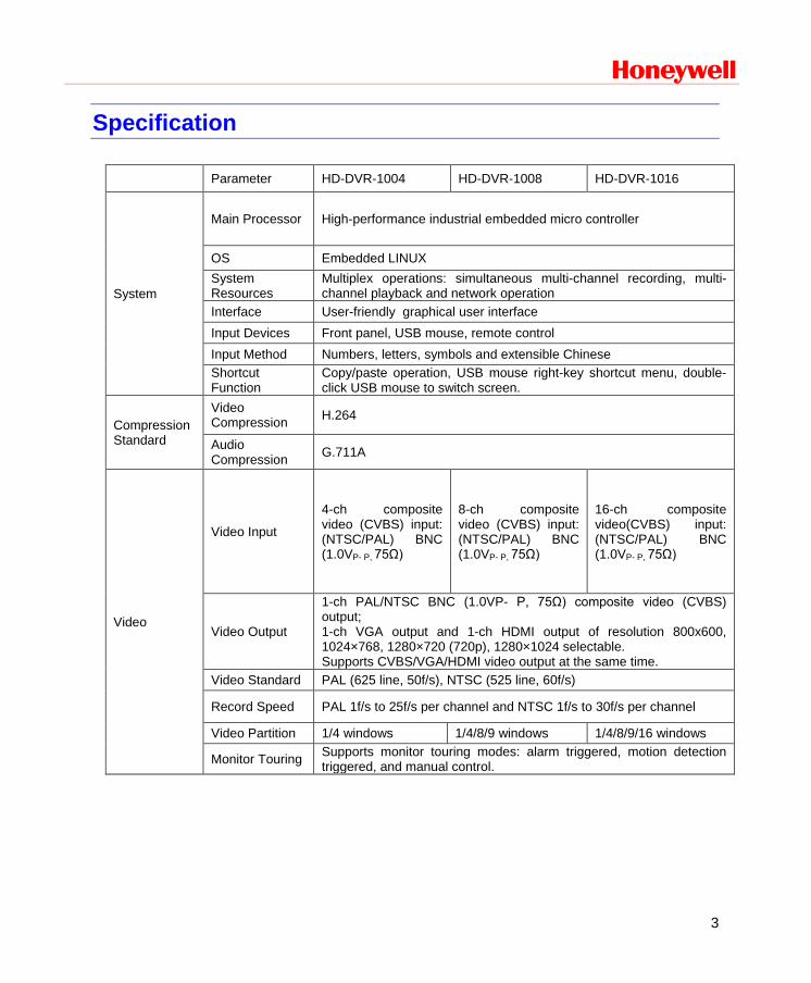
Specification
Parameter HD-DVR-1004 HD-DVR-1008 HD-DVR-1016
System
Main Processor High-performance industrial embedded micro controller
OS Embedded LINUX System Resources
Multiplex operations: simultaneous multi-channel recording, multi-channel playback and network operation
Interface User-friendly graphical user interface Input Devices Front panel, USB mouse, remote control Input Method Numbers, letters, symbols and extensible Chinese Shortcut Function
Copy/paste operation, USB mouse right-key shortcut menu, double-click USB mouse to switch screen.
Compression Standard
Video Compression H.264
Audio Compression G.711A
Video
Video Input
4-ch composite video (CVBS) input: (NTSC/PAL) BNC (1.0VP- P, 75Ω)
8-ch composite video (CVBS) input: (NTSC/PAL) BNC (1.0VP- P, 75Ω)
16-ch composite video(CVBS) input: (NTSC/PAL) BNC (1.0VP- P, 75Ω)
Video Output
1-ch PAL/NTSC BNC (1.0VP- P, 75Ω) composite video (CVBS) output; 1-ch VGA output and 1-ch HDMI output of resolution 800x600, 1024×768, 1280×720 (720p), 1280×1024 selectable. Supports CVBS/VGA/HDMI video output at the same time.
Video Standard PAL (625 line, 50f/s), NTSC (525 line, 60f/s)
Record Speed PAL 1f/s to 25f/s per channel and NTSC 1f/s to 30f/s per channel
Video Partition 1/4 windows 1/4/8/9 windows 1/4/8/9/16 windows
Monitor Touring Supports monitor touring modes: alarm triggered, motion detection triggered, and manual control.
Features and Specifications
4
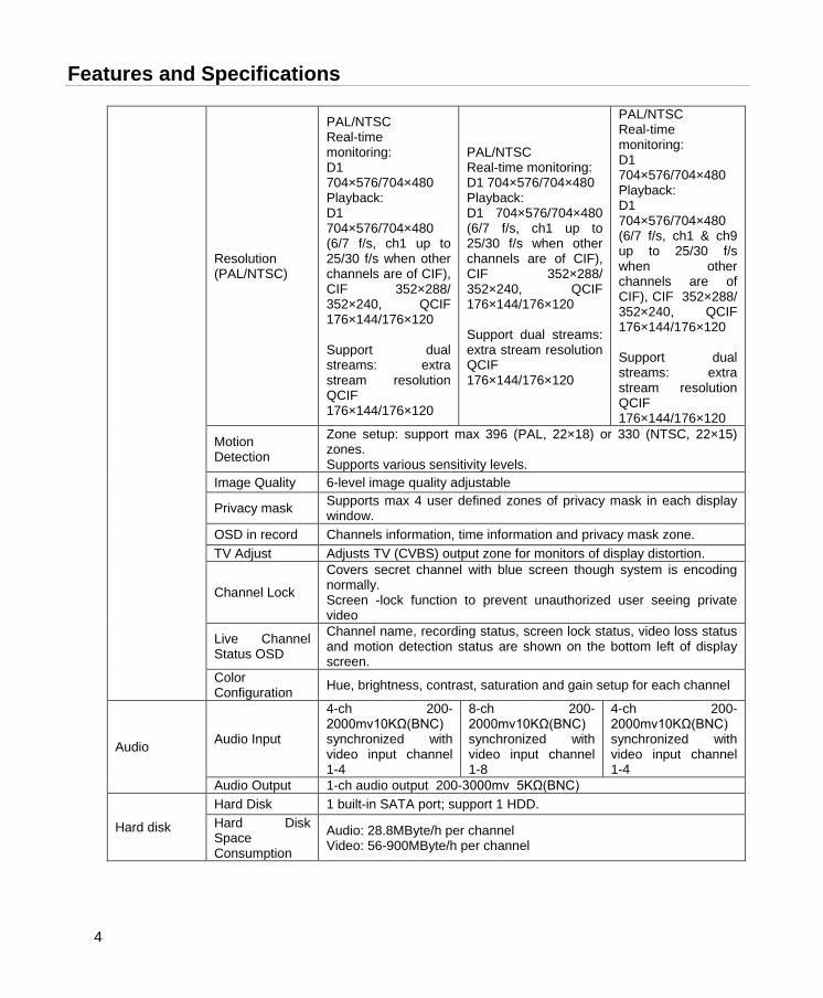
Resolution (PAL/NTSC)
PAL/NTSC Real-time monitoring: D1 704×576/704×480 Playback: D1 704×576/704×480 (6/7 f/s, ch1 up to 25/30 f/s when other channels are of CIF), CIF 352×288/ 352×240, QCIF 176×144/176×120 Support dual streams: extra stream resolution QCIF 176×144/176×120
PAL/NTSC Real-time monitoring: D1 704×576/704×480 Playback: D1 704×576/704×480 (6/7 f/s, ch1 up to 25/30 f/s when other channels are of CIF), CIF 352×288/ 352×240, QCIF 176×144/176×120 Support dual streams: extra stream resolution QCIF 176×144/176×120
PAL/NTSC Real-time monitoring: D1 704×576/704×480 Playback: D1 704×576/704×480 (6/7 f/s, ch1 & ch9 up to 25/30 f/s when other channels are of CIF), CIF 352×288/ 352×240, QCIF 176×144/176×120 Support dual streams: extra stream resolution QCIF 176×144/176×120
Motion Detection
Zone setup: support max 396 (PAL, 22×18) or 330 (NTSC, 22×15) zones. Supports various sensitivity levels.
Image Quality 6-level image quality adjustable
Privacy mask Supports max 4 user defined zones of privacy mask in each display window.
OSD in record Channels information, time information and privacy mask zone. TV Adjust Adjusts TV (CVBS) output zone for monitors of display distortion.
Channel Lock
Covers secret channel with blue screen though system is encoding normally. Screen -lock function to prevent unauthorized user seeing private video
Live Channel Status OSD
Channel name, recording status, screen lock status, video loss status and motion detection status are shown on the bottom left of display screen.
Color Configuration Hue, brightness, contrast, saturation and gain setup for each channel
Audio Audio Input
4-ch 200-2000mv10KΩ(BNC) synchronized with video input channel 1-4
8-ch 200-2000mv10KΩ(BNC) synchronized with video input channel 1-8
4-ch 200-2000mv10KΩ(BNC) synchronized with video input channel 1-4
Audio Output 1-ch audio output 200-3000mv 5KΩ(BNC)
Hard disk
Hard Disk 1 built-in SATA port; support 1 HDD. Hard Disk Space Consumption
Audio: 28.8MByte/h per channel Video: 56-900MByte/h per channel

Honeywell
5
Record and playback
Recording Mode
Manual recording, motion detection recording, schedule recording and alarm recording Priority: Manual recording> alarm recording>motion detection recording>schedule recording
Recording Length 1 to 120 minutes single record duration (Default 60 minutes)
Cyclic mode When hard disk is full, system can overwrite previous video file. Record Search Various search engines such as time, type and channel.
Playback Mode Various fast play, slow play speeds, manual frame by frame playback and reverse play mode.
Various File Switch Ways
Can switch to previous or next file or any file in current play list. Can switch to file on other channel of the same time (if existing). Supports continuous file playback; when a file is ended, system automatically plays the next file in the current channel
Multi-channel Playback
Support maximum 4-channel simultaneous playback.
Support maximum 8-channel simultaneous playback.
Support maximum 16-channel simultaneous playback.
Display Modes Switch between adaptive window/full screen during playback
Zoom When in one-window full-screen playback mode, you can select any zone to zoom in.
Backup function Backup Mode
HDD backup Support peripheral USB backup device. (Flash disk, portable HDD and etc.) Supports USB burner (extension function). Supports network download and backup
Network Function Network control
Remote live view of all channels. DVR configuration through web browser client Upgrade or maintenance via web browser client View alarm information such as external alarm, motion detection and video loss Supports network PTZ control File download backup and playback Duplex transparent COM Intercom
Motion Detection and Alarm
Motion Detection
Zone setup: 396 (PAL, 22×18) or 330 (NTSC, 22×15) detection zones. Various sensitivity levels Can activate recording, external alarm or screen message prompt in specified period.
Video Loss Alarm can activate external alarm or screen message prompt.
External Alarm Can activate recording, external alarm or screen message prompt in specified period.
Manual Alarm Control
Enables or disables alarm input channel. Supports manual alarm output.
Alarm Input 4-ch alarm input( Normal open or normal close)
8-ch alarm input( Normal open or normal close)
16-ch alarm input( Normal open or normal close)
Features and Specifications
6
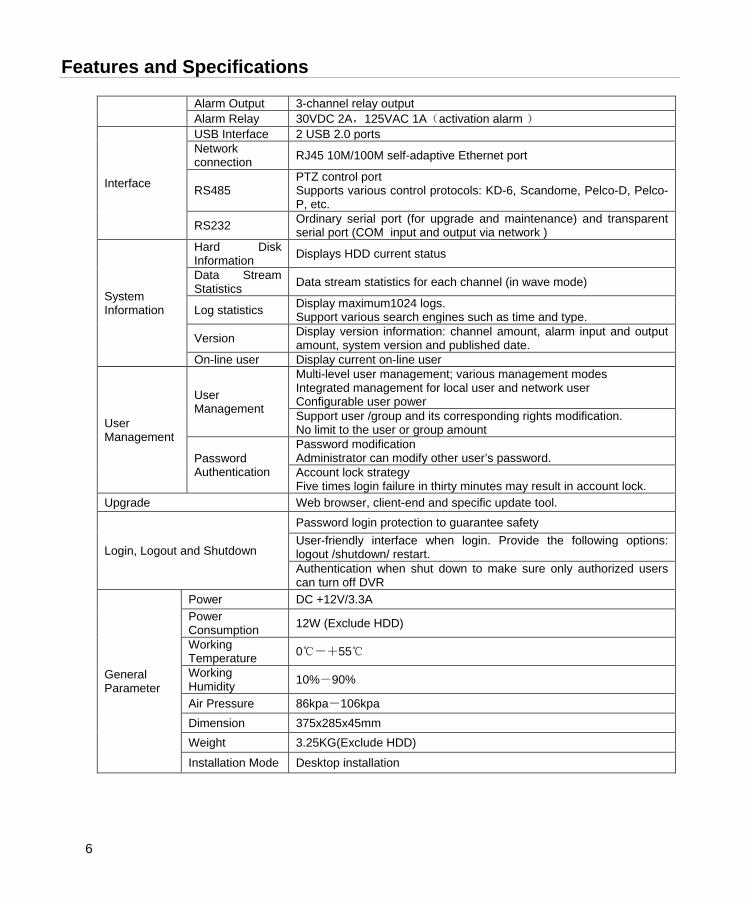
Alarm Output 3-channel relay output Alarm Relay 30VDC 2A,125VAC 1A(activation alarm )
Interface
USB Interface 2 USB 2.0 ports Network connection RJ45 10M/100M self-adaptive Ethernet port
RS485 PTZ control port Supports various control protocols: KD-6, Scandome, Pelco-D, Pelco-P, etc.
RS232 Ordinary serial port (for upgrade and maintenance) and transparent serial port (COM input and output via network )
System Information
Hard Disk Information Displays HDD current status
Data Stream Statistics Data stream statistics for each channel (in wave mode)
Log statistics Display maximum1024 logs. Support various search engines such as time and type.
Version Display version information: channel amount, alarm input and output amount, system version and published date.
On-line user Display current on-line user
User Management
User Management
Multi-level user management; various management modes Integrated management for local user and network user Configurable user power Support user /group and its corresponding rights modification. No limit to the user or group amount
Password Authentication
Password modification Administrator can modify other user’s password. Account lock strategy Five times login failure in thirty minutes may result in account lock.
Upgrade Web browser, client-end and specific update tool.
Login, Logout and Shutdown
Password login protection to guarantee safety User-friendly interface when login. Provide the following options: logout /shutdown/ restart. Authentication when shut down to make sure only authorized users can turn off DVR
General Parameter
Power DC +12V/3.3A Power Consumption 12W (Exclude HDD)
Working Temperature 0℃-+55℃
Working Humidity 10%-90%
Air Pressure 86kpa-106kpa Dimension 375x285x45mm Weight 3.25KG(Exclude HDD)
Installation Mode Desktop installation
Honeywell
7
2 Overview and Controls
This section provides information about front panel and rear panel. When you install this series DVR for the first time, please refer to this part first.
Front Panel
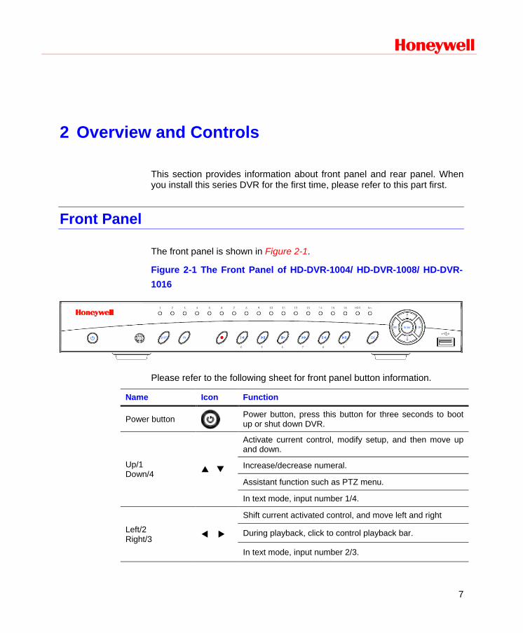
The front panel is shown in Figure 2-1.
Figure 2-1 The Front Panel of HD-DVR-1004/ HD-DVR-1008/ HD-DVR-1016
Please refer to the following sheet for front panel button information.
Name Icon Function
Power button
Power button, press this button for three seconds to boot up or shut down DVR.
Up/1 Down/4
Activate current control, modify setup, and then move up and down.
Increase/decrease numeral.
Assistant function such as PTZ menu.
In text mode, input number 1/4.
Left/2 Right/3
Shift current activated control, and move left and right
During playback, click to control playback bar.
In text mode, input number 2/3.
Overview and Controls
8
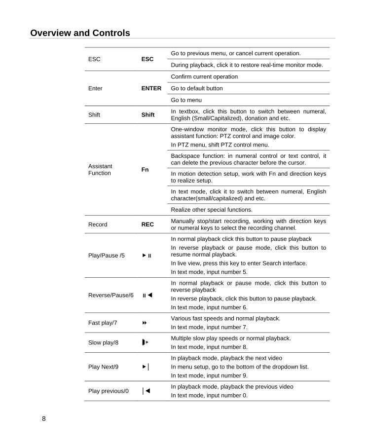
ESC ESC Go to previous menu, or cancel current operation.
During playback, click it to restore real-time monitor mode.
Enter ENTER
Confirm current operation
Go to default button
Go to menu
Shift Shift In textbox, click this button to switch between numeral, English (Small/Capitalized), donation and etc.
Assistant Function Fn
One-window monitor mode, click this button to display assistant function: PTZ control and image color. In PTZ menu, shift PTZ control menu.
Backspace function: in numeral control or text control, it can delete the previous character before the cursor.
In motion detection setup, work with Fn and direction keys to realize setup.
In text mode, click it to switch between numeral, English character(small/capitalized) and etc.
Realize other special functions.
Record REC Manually stop/start recording, working with direction keys or numeral keys to select the recording channel.
Play/Pause /5
In normal playback click this button to pause playback In reverse playback or pause mode, click this button to resume normal playback. In live view, press this key to enter Search interface. In text mode, input number 5.
Reverse/Pause/6
In normal playback or pause mode, click this button to reverse playback In reverse playback, click this button to pause playback. In text mode, input number 6.
Fast play/7 Various fast speeds and normal playback. In text mode, input number 7.
Slow play/8 Multiple slow play speeds or normal playback. In text mode, input number 8.
Play Next/9 │ In playback mode, playback the next video In menu setup, go to the bottom of the dropdown list. In text mode, input number 9.
Play previous/0 │ In playback mode, playback the previous video In text mode, input number 0.
Honeywell
9
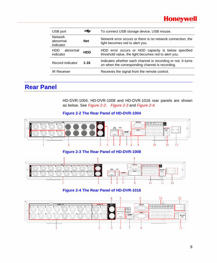
USB port To connect USB storage device, USB mouse. Network abnormal indicator
Net Network error occurs or there is no network connection, the light becomes red to alert you.
HDD abnormal indicator HDD HDD error occurs or HDD capacity is below specified
threshold value, the light becomes red to alert you.
Record indicator 1-16 Indicates whether each channel is recording or not. It turns on when the corresponding channel is recording.
IR Receiver Receives the signal from the remote control.
Rear Panel
HD-DVR-1004, HD-DVR-1008 and HD-DVR-1016 rear panels are shown as below. See Figure 2-2, Figure 2-3 and Figure 2-4.
Figure 2-2 The Rear Panel of HD-DVR-1004
Figure 2-3 The Rear Panel of HD-DVR-1008
Figure 2-4 The Rear Panel of HD-DVR-1016
Overview and Controls
10
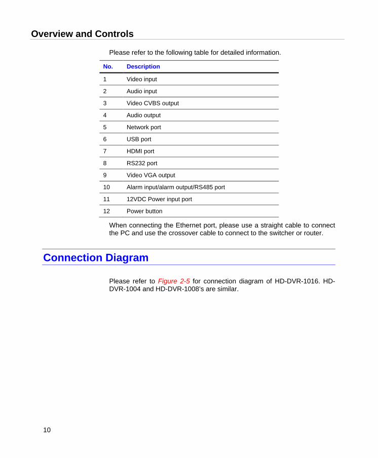
Please refer to the following table for detailed information.
No. Description
1 Video input
2 Audio input
3 Video CVBS output
4 Audio output
5 Network port
6 USB port
7 HDMI port
8 RS232 port
9 Video VGA output
10 Alarm input/alarm output/RS485 port
11 12VDC Power input port
12 Power button
When connecting the Ethernet port, please use a straight cable to connect the PC and use the crossover cable to connect to the switcher or router.
Connection Diagram
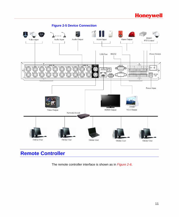
Please refer to Figure 2-5 for connection diagram of HD-DVR-1016. HD-DVR-1004 and HD-DVR-1008’s are similar.
Honeywell
11
Figure 2-5 Device Connection
Remote Controller
The remote controller interface is shown as in Figure 2-6.
Overview and Controls
12
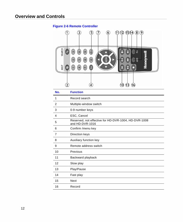
Figure 2-6 Remote Controller
No. Function
1 Record search
2 Multiple-window switch
3 0-9 number keys
4 ESC, Cancel
5 Reserved, not effective for HD-DVR-1004, HD-DVR-1008 and HD-DVR-1016
6 Confirm /menu key
7 Direction keys
8 Auxiliary function key
9 Remote address switch
10 Previous
11 Backward playback
12 Slow play
13 Play/Pause
14 Fast play
15 Next
16 Record
Honeywell
13
Mouse Control
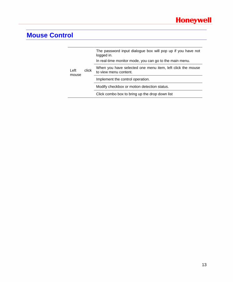
Left click mouse
The password input dialogue box will pop up if you have not logged in. In real-time monitor mode, you can go to the main menu.
When you have selected one menu item, left click the mouse to view menu content.
Implement the control operation.
Modify checkbox or motion detection status.
Click combo box to bring up the drop down list
Overview and Controls
14
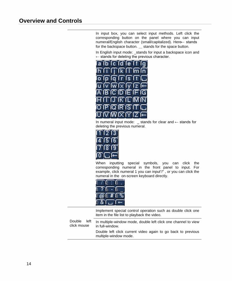
In input box, you can select input methods. Left click the corresponding button on the panel where you can input numeral/English character (small/capitalized). Here ← stands for the backspace button. _ stands for the space button. In English input mode: _stands for input a backspace icon and ← stands for deleting the previous character.
In numeral input mode: _ stands for clear and ← stands for deleting the previous numeral.
When inputting special symbols, you can click the corresponding numeral in the front panel to input. For example, click numeral 1 you can input“/” , or you can click the numeral in the on-screen keyboard directly.
Double left click mouse
Implement special control operation such as double click one item in the file list to playback the video.
In multiple-window mode, double left click one channel to view in full-window. Double left click current video again to go back to previous multiple-window mode.
Honeywell
15
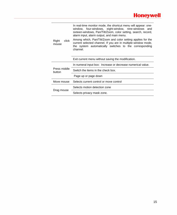
Right click mouse
In real-time monitor mode, the shortcut menu will appear: one-window, four-windows, eight-window, nine-windows and sixteen-windows, Pan/Tilt/Zoom, color setting, search, record, alarm input, alarm output, and main menu. Among which, Pan/Tilt/Zoom and color setting applies for the current selected channel. If you are in multiple-window mode, the system automatically switches to the corresponding channel.
Exit current menu without saving the modification.
Press middle button
In numeral input box: Increase or decrease numerical value.
Switch the items in the check box.
Page up or page down
Move mouse Selects current control or move control
Drag mouse Selects motion detection zone
Selects privacy mask zone.
Installation and Connections
16
3 Installation and Connections
Note All the installation and operations here should conform to your local electrical safety rules
Unpack Everything
Be sure to use all the accessories recommended by the manufacturer.
Before installation, please open the package and check that all the components are included.
• Software CD
• USB mouse
• Network cable
• 12VDC power adapter
• Power cord
• SATA data cable and screws for HDD installation
• User manual
• Remote controller
• 4 BNC connectors (only in HD-DVR-1004 package)
• HDMI cable
Contact your local retailer ASAP if something is broken in your package.
Honeywell
17
HDD Installation
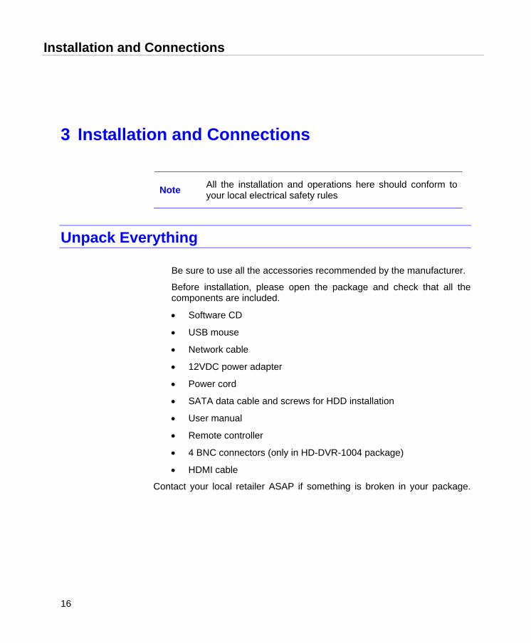
This series DVR has only one SATA HDD. Please use HDD of 7200rpm or higher.
You can refer to the user guide for a recommended HDD brand.
Please follow the instructions below to install the hard disk.
1. Loosen the screws of the upper cover.
2. Remove upper cover
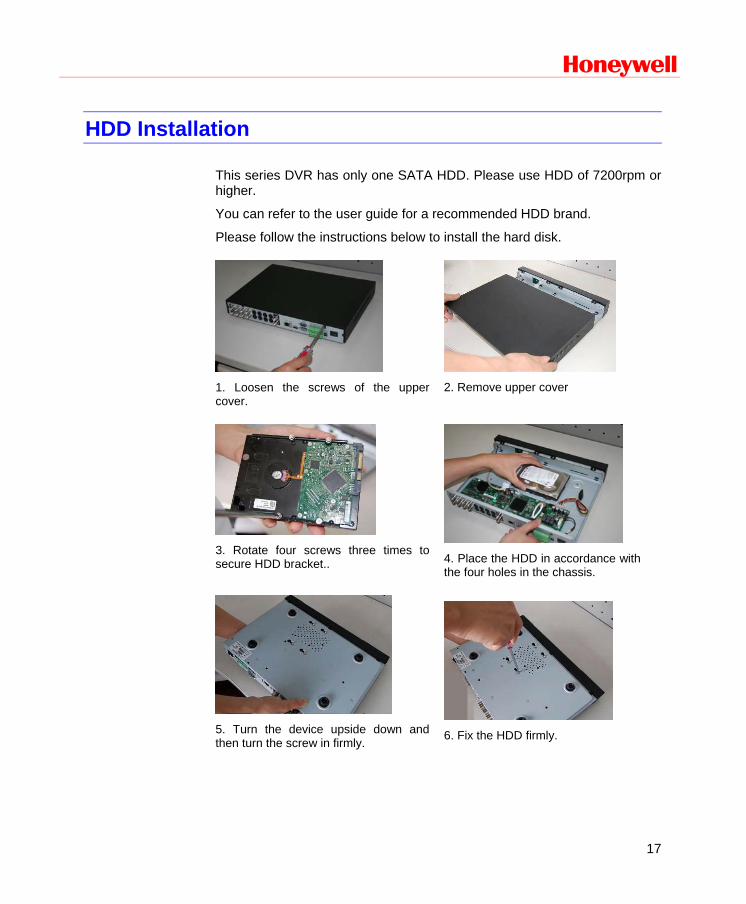
3. Rotate four screws three times to secure HDD bracket..
4. Place the HDD in accordance with the four holes in the chassis.
5. Turn the device upside down and then turn the screw in firmly.
6. Fix the HDD firmly.
Installation and Connections
18
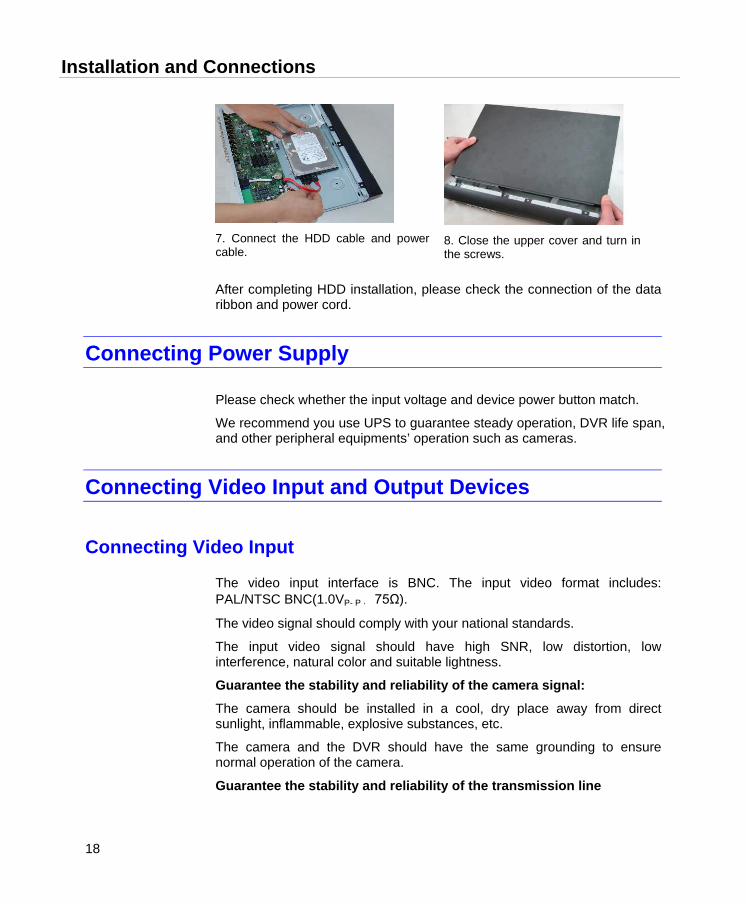
7. Connect the HDD cable and power cable.
8. Close the upper cover and turn in the screws.
After completing HDD installation, please check the connection of the data ribbon and power cord.
Connecting Power Supply
Please check whether the input voltage and device power button match.
We recommend you use UPS to guarantee steady operation, DVR life span, and other peripheral equipments’ operation such as cameras.
Connecting Video Input and Output Devices
Connecting Video Input
The video input interface is BNC. The input video format includes: PAL/NTSC BNC(1.0VP- P , 75Ω).
The video signal should comply with your national standards.
The input video signal should have high SNR, low distortion, low interference, natural color and suitable lightness.
Guarantee the stability and reliability of the camera signal:
The camera should be installed in a cool, dry place away from direct sunlight, inflammable, explosive substances, etc.
The camera and the DVR should have the same grounding to ensure normal operation of the camera.
Guarantee the stability and reliability of the transmission line
Honeywell
19
Please use high quality, sound shielded BNC. Please select suitable BNC model according to the transmission distance.
If the distance is too long, you should use twisted pair cable, and you can add video compensation devices or use optical fiber to ensure video quality.
You should keep the video signal away from the strong electromagnetic interference, especially the high tension current.
Keep connection lugs in well contact The signal line and shielded wire should be fixed firmly and in well connection. Avoid dry joint, lap welding and oxidation.
Connecting Video Output
Video output includes BNC (CVBS PAL/NTSC, 1.0VP-P, 75Ω), VGA and HDMI. The system supports the three kinds of outputs at the same time.
When you are using PC monitor to replace standard CCTV monitor, please pay attention to the following points:
• To extend the product’s life, do not run the pc monitor for a long time.
• Regular demagnetization will keep device maintaining proper status.
• Keep it away from strong electromagnetic interference devices. Using TV as video output device is not a reliable substitution method. You also need to reduce the working hour and control the interference from power supply and other devices. The low quality TV may result in device damage.
Connecting Audio Input & Output
Audio Input
The four audio input channels are bound to video input channel 1-4.
Use the BNC connector to connect the audio channel.
Due to high impedance of audio input, please use active sound pick-up.
Audio transmission is similar to video transmission. Try to avoid interference, dry joint, and it shall be away from high tension current
Installation and Connections
20
Audio Output
The audio output signal parameter is usually over 200mv 1KΩ (BNC). It can directly connect to low impedance earphones, active sound box or amplifier-drive audio output device.
If the sound box and the pick-up cannot be separated spatially, it is easy to cause a squeaking noise. In this case you can adopt the following measures:
• Use better sound pick-up with better directing property.
• Reduce the volume of the sound box.
• Use more sound-absorbing materials in decoration to reduce voice echo and improve acoustics environment.
• Adjust the layout to reduce the occurrence of the squeaking.
Alarm Input and Output Connection
Please refer to the following sheet for alarm input and output connection.
There are two alarm input types for you to select: normal open (NO) and normal close (NC).
1. Alarm input
a Please make sure alarm input mode is grounding alarm input.
b Grounding signal is needed for alarm input.
c When you are connecting two DVRs or connecting one DVR and one other device, please use a relay to separate them
2. Alarm output
The alarm output port should not be connected to a high power load directly (It shall be less than 1A) to avoid high current which may result in relay damage. Please use the co contactor to realize the connection between the alarm output port and the load.
3. Please make sure the front-end devices have been well earthed.
Improper grounding may result in chip damage.
Honeywell
21
Alarm Input and Output Details
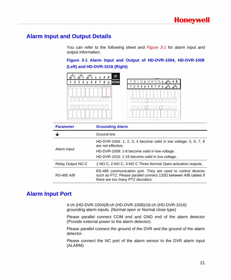
You can refer to the following sheet and Figure 3-1 for alarm input and output information.
Figure 3-1 Alarm Input and Output of HD-DVR-1004, HD-DVR-1008 (Left) and HD-DVR-1016 (Right)
Parameter Grounding Alarm
Ground line
Alarm Input
HD-DVR-1004: 1, 2, 3, 4 become valid in low voltage; 5, 6, 7, 8 are not effective. HD-DVR-1008: 1-8 become valid in low voltage. HD-DVR-1016: 1-16 become valid in low voltage.
Relay Output NO C 1-NO C, 2-NO C, 3-NO C Three Normal Open activation outputs.
RS-485 A/B RS-485 communication port. They are used to control devices such as PTZ. Please parallel connect 120Ω between A/B cables if there are too many PTZ decoders.
Alarm Input Port
4-ch (HD-DVR-1004)/8-ch (HD-DVR-1008)/16-ch (HD-DVR-1016) grounding alarm inputs. (Normal open or Normal close type)
Please parallel connect COM end and GND end of the alarm detector (Provide external power to the alarm detector).
Please parallel connect the ground of the DVR and the ground of the alarm detector.
Please connect the NC port of the alarm sensor to the DVR alarm input (ALARM)
Installation and Connections
22
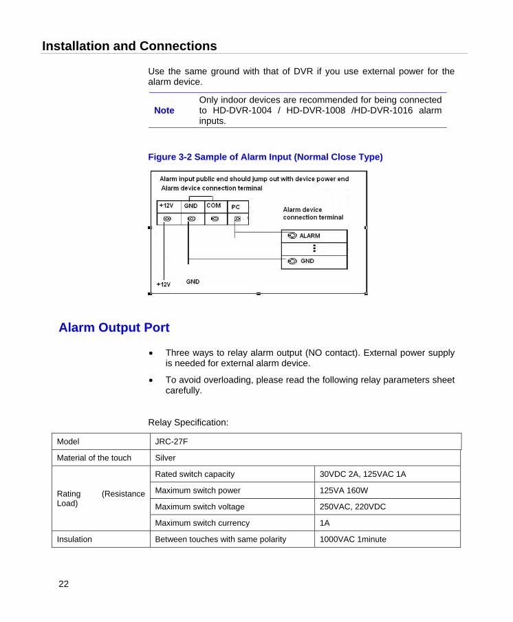
Use the same ground with that of DVR if you use external power for the alarm device.
Note Only indoor devices are recommended for being connected to HD-DVR-1004 / HD-DVR-1008 /HD-DVR-1016 alarm inputs.
Figure 3-2 Sample of Alarm Input (Normal Close Type)
Alarm Output Port
• Three ways to relay alarm output (NO contact). External power supply is needed for external alarm device.
• To avoid overloading, please read the following relay parameters sheet carefully.
Relay Specification:
Model JRC-27F
Material of the touch Silver
Rating (Resistance Load)
Rated switch capacity 30VDC 2A, 125VAC 1A
Maximum switch power 125VA 160W
Maximum switch voltage 250VAC, 220VDC
Maximum switch currency 1A
Insulation Between touches with same polarity 1000VAC 1minute
Honeywell
23
Between touches with different polarity 1000VAC 1minute
Between touch and winding 1000VAC 1minute
Surge voltage Between touches with same polarity 1500V (10×160us)
Length of open time 3ms max
Length of closed time 3ms max
Longevity Mechanical 50×106 times (3Hz)
Electrical 200×103 times (0.5Hz)
Temperature -40℃ ~ +70℃
RS232
RS232 port is reserved for technical support diagnosis and upgrade.
RS485
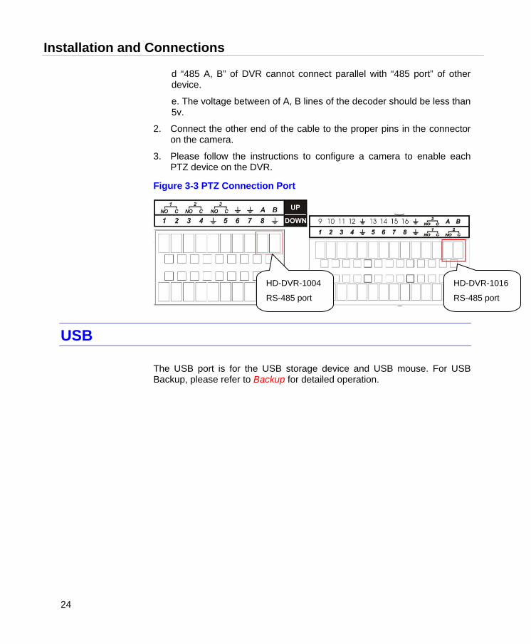
When the DVR receives a camera control command, it transmits that command up the coaxial cable to the PTZ device. RS485 is a single-direction protocol; the PTZ device cannot return any data to the unit. To enable the operation, connect the PTZ device to the RS485 (A,B) input on the DVR. See Figure 3-3.
Since RS485 is disabled by default for each camera, you must enable the PTZ settings first. This series DVRs support multiple protocols such as Pelco-D, Pelco-P.
To connect PTZ devices to the DVR:
1. Connect RS485 A,B on the DVR rear panel.
a. Ensure the decoder has the same grounding with the DVR, otherwise you will not be able to control the PTZ. Shielded twisted wire is recommended, and the shielded layer should be used to connect the ground.
b. Avoid high voltage. Ensure proper wiring and some thunder protection measures.
c. For signal wires that are too long, 120Ω should be connected parallel between A, B lines on the far end to reduce reflection and guarantee signal quality.
Installation and Connections
24
d “485 A, B” of DVR cannot connect parallel with “485 port” of other device.
e. The voltage between of A, B lines of the decoder should be less than 5v.
2. Connect the other end of the cable to the proper pins in the connector on the camera.
3. Please follow the instructions to configure a camera to enable each PTZ device on the DVR.
Figure 3-3 PTZ Connection Port
USB
The USB port is for the USB storage device and USB mouse. For USB Backup, please refer to Backup for detailed operation.
HD-DVR-1004
RS-485 port HD-DVR-1016
RS-485 port

Honeywell
25
4 Overview of Navigation and Controls
Before operation, please make sure you have properly installed HDD and all the cable connections.
Note From this chapter, most descriptions and figures are based on HD-DVR-1016 operation.
Login, Logout & Main Menu
Login
After the system has booted up, default video display will be in multiple-window mode.
Press Enter on the from panel, or Menu on the remote controller, or left click the mouse. You will be able to see the login interface. See Figure 4-1.
The system consists of four accounts:
• Username: admin. Password: admin. (administrator, local and network)
• Username: 888888. Password: 888888. (administrator, local only)
• Username: 666666. Password: 666666(Lower authority user who can only monitor, playback, backup and etc.)
• Username: default. Password: default(hidden user)
You can use the USB mouse, front panel, remote controller or keyboard to
input. About input method: Click or press Shift on the front panel to switch between numbers, English character (small/capitalized) and denotation.
Note For security reasons, please modify the password after your first login.
Overview of Navigation and Controls
26
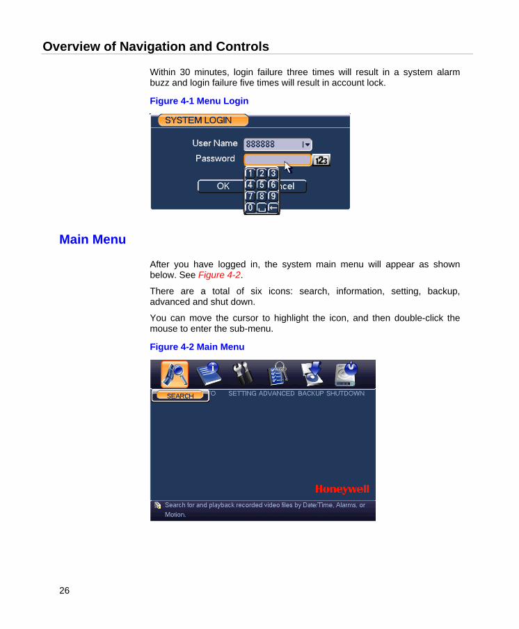
Within 30 minutes, login failure three times will result in a system alarm buzz and login failure five times will result in account lock.
Figure 4-1 Menu Login
Main Menu
After you have logged in, the system main menu will appear as shown below. See Figure 4-2.
There are a total of six icons: search, information, setting, backup, advanced and shut down.
You can move the cursor to highlight the icon, and then double-click the mouse to enter the sub-menu.
Figure 4-2 Main Menu
Honeywell
27
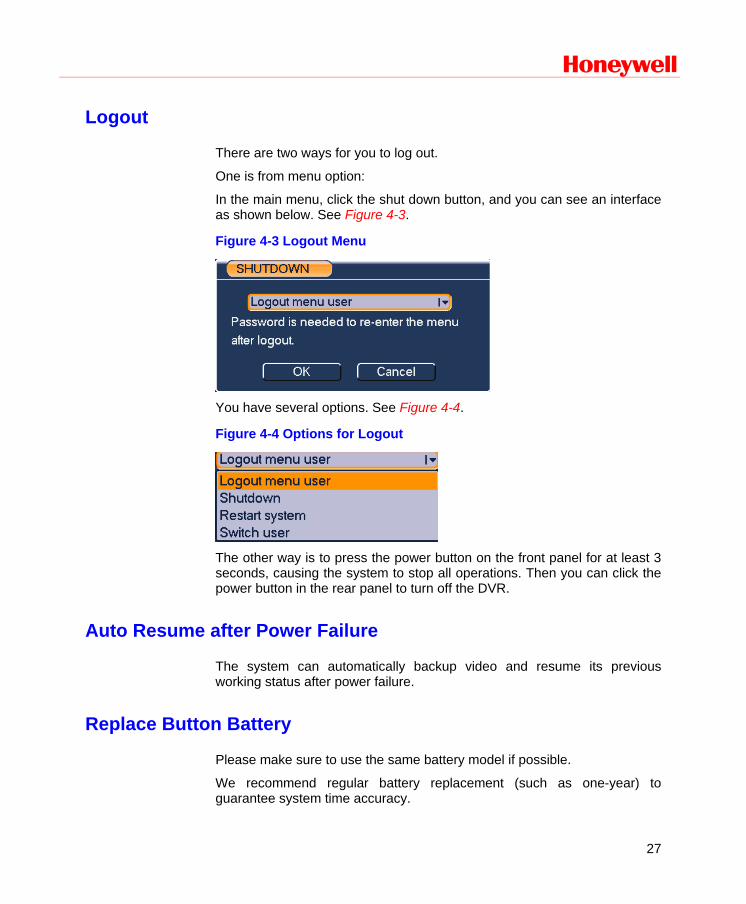
Logout
There are two ways for you to log out.
One is from menu option:
In the main menu, click the shut down button, and you can see an interface as shown below. See Figure 4-3.
Figure 4-3 Logout Menu
You have several options. See Figure 4-4.
Figure 4-4 Options for Logout
The other way is to press the power button on the front panel for at least 3 seconds, causing the system to stop all operations. Then you can click the power button in the rear panel to turn off the DVR.
Auto Resume after Power Failure
The system can automatically backup video and resume its previous working status after power failure.
Replace Button Battery
Please make sure to use the same battery model if possible.
We recommend regular battery replacement (such as one-year) to guarantee system time accuracy.

Overview of Navigation and Controls
28
Manual Record
Live Viewing
After you have logged in, the system is in live viewing mode. You can see the system date, time and channel name. If you want to change the system date and time, you can refer to general settings (Main MenuSettingGeneral). If you want to modify the channel name, refer to the display settings (Main MenuSettingDisplay).
1 Recording status 3 Video loss
2
Motion detection 4 Camera lock
Note Live audio will only be played under the single channel video display mode.
Manual Record
Note You need to have proper rights to implement the following operations. Please make sure the HDD has been properly installed.
Manual Record Menu There are two ways for you to go to the manual record menu.
• Right-click the mouse to select Record, or in the main menu proceed to AdvancedManual Record.
• In live viewing mode, click the record button in the front panel or the record button in the remote control.
Manual record menu is shown in Figure 4-5.
Basic Operations There are three modes: schedule/manual/stop. Please highlight icon”○” to select the corresponding channel.
Honeywell
29
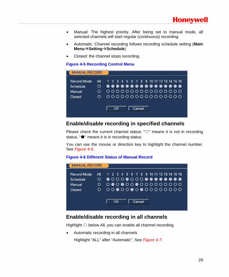
• Manual: The highest priority. After being set to manual mode, all selected channels will start regular (continuous) recording.
• Automatic: Channel recording follows recording schedule setting (Main MenuSettingSchedule)
• Closed: the channel stops recording.
Figure 4-5 Recording Control Menu
Enable/disable recording in specified channels Please check the current channel status: “○” means it is not in recording status, “●” means it is in recording status.
You can use the mouse or direction key to highlight the channel number. See Figure 4-6.
Figure 4-6 Different Status of Manual Record
Enable/disable recording in all channels Highlight ○ below All, you can enable all channel recording.
• Automatic recording in all channels
Highlight “ALL” after “Automatic”. See Figure 4-7.
Overview of Navigation and Controls
30
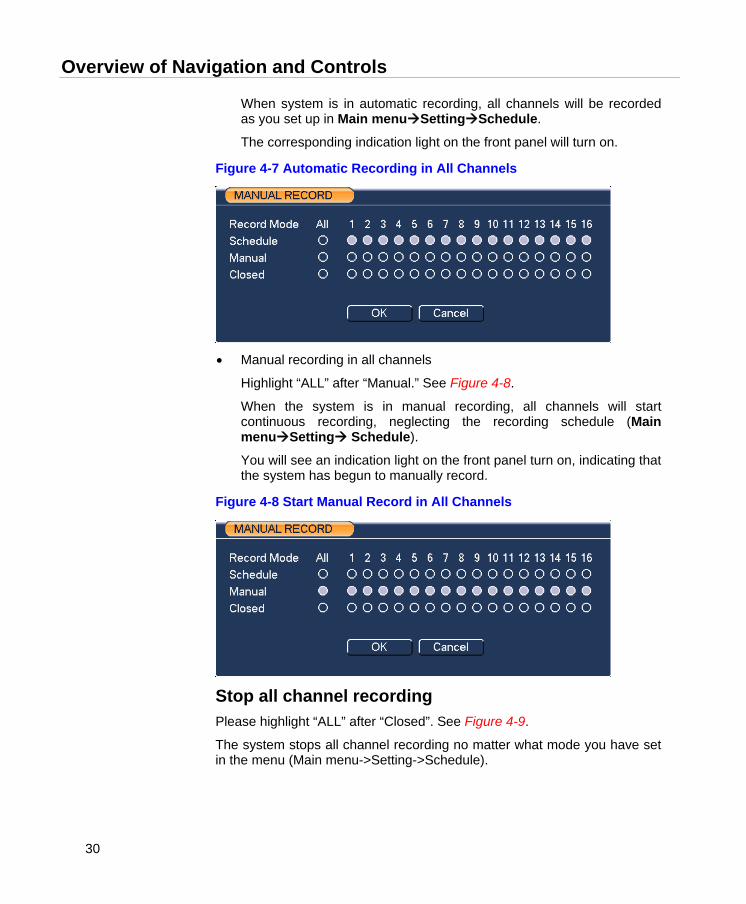
When system is in automatic recording, all channels will be recorded as you set up in Main menuSettingSchedule.
The corresponding indication light on the front panel will turn on.
Figure 4-7 Automatic Recording in All Channels
• Manual recording in all channels
Highlight “ALL” after “Manual.” See Figure 4-8.
When the system is in manual recording, all channels will start continuous recording, neglecting the recording schedule (Main menuSetting Schedule).
You will see an indication light on the front panel turn on, indicating that the system has begun to manually record.
Figure 4-8 Start Manual Record in All Channels
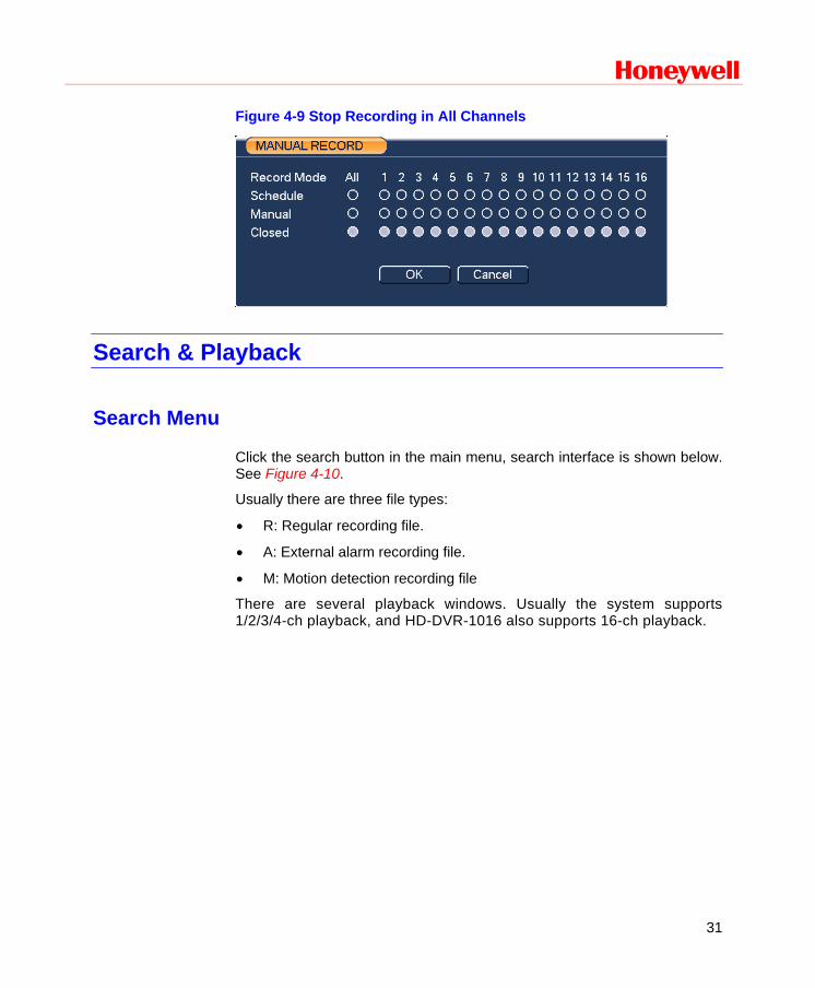
Stop all channel recording Please highlight “ALL” after “Closed”. See Figure 4-9.
The system stops all channel recording no matter what mode you have set in the menu (Main menu->Setting->Schedule).
Honeywell
31
Figure 4-9 Stop Recording in All Channels
Search & Playback
Search Menu
Click the search button in the main menu, search interface is shown below. See Figure 4-10.
Usually there are three file types:
• R: Regular recording file.
• A: External alarm recording file.
• M: Motion detection recording file
There are several playback windows. Usually the system supports 1/2/3/4-ch playback, and HD-DVR-1016 also supports 16-ch playback.
Overview of Navigation and Controls
32
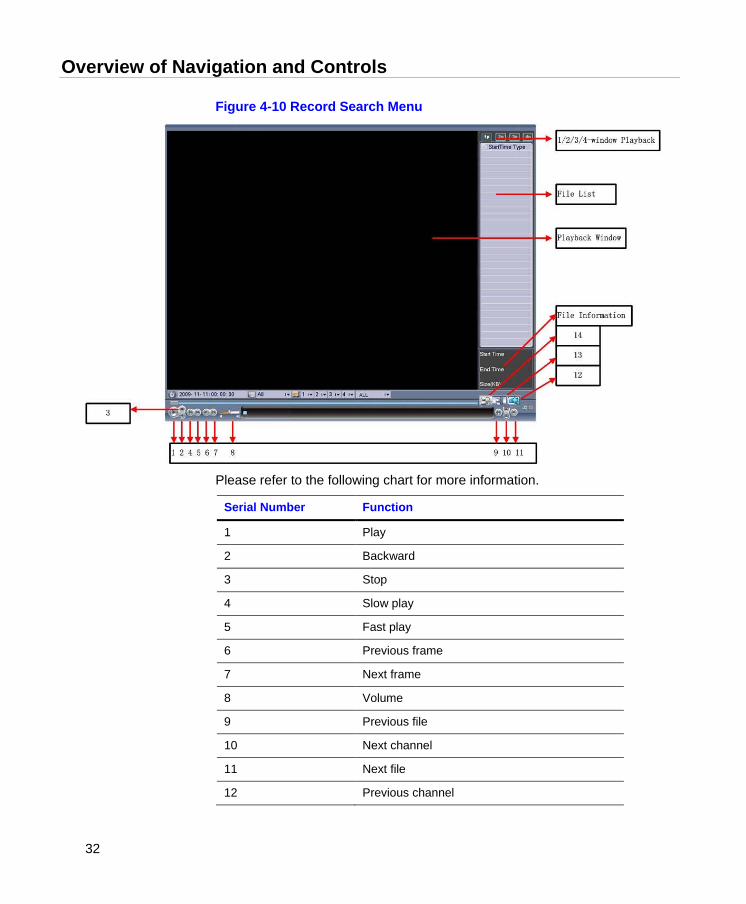
Figure 4-10 Record Search Menu
Please refer to the following chart for more information.
Serial Number Function
1 Play
2 Backward
3 Stop
4 Slow play
5 Fast play
6 Previous frame
7 Next frame
8 Volume
9 Previous file
10 Next channel
11 Next file
12 Previous channel
Honeywell
33
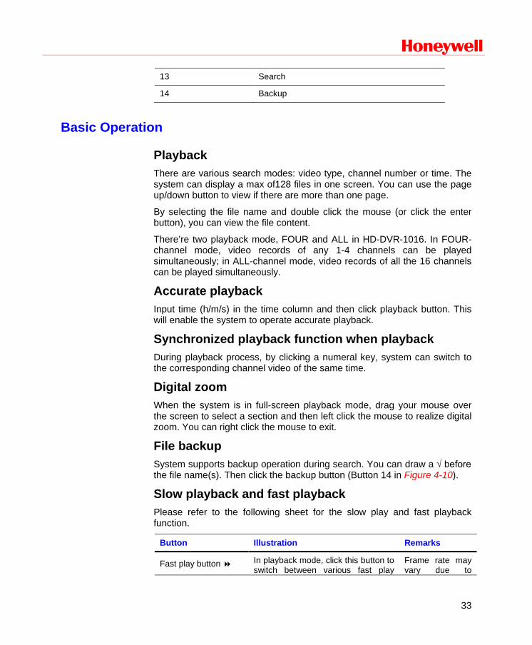
13 Search
14 Backup
Basic Operation
Playback There are various search modes: video type, channel number or time. The system can display a max of128 files in one screen. You can use the page up/down button to view if there are more than one page.
By selecting the file name and double click the mouse (or click the enter button), you can view the file content.
There’re two playback mode, FOUR and ALL in HD-DVR-1016. In FOUR-channel mode, video records of any 1-4 channels can be played simultaneously; in ALL-channel mode, video records of all the 16 channels can be played simultaneously.
Accurate playback Input time (h/m/s) in the time column and then click playback button. This will enable the system to operate accurate playback.
Synchronized playback function when playback During playback process, by clicking a numeral key, system can switch to the corresponding channel video of the same time.
Digital zoom When the system is in full-screen playback mode, drag your mouse over the screen to select a section and then left click the mouse to realize digital zoom. You can right click the mouse to exit.
File backup System supports backup operation during search. You can draw a √ before the file name(s). Then click the backup button (Button 14 in Figure 4-10).
Slow playback and fast playback Please refer to the following sheet for the slow play and fast playback function.
Button Illustration Remarks
Fast play button In playback mode, click this button to switch between various fast play
Frame rate may vary due to
Overview of Navigation and Controls
34
modes such as fast play 1, fast play 2 and more.
different versions.
Slow play button ► In playback mode, click this button to switch between various slow play modes such as slow play 1 or slow play 2.
Play/Pause ►/ In normal/fast/slow playback mode, click this button to switch between play/pause modes.
Previous/next In playback mode, you can click │ and │ to view previous or next video in current channel.
Backward playback and frame by frame playback Button Illustration Remarks
Backward play: in playback interface.
In normal playback mode, left click the backward play button , system begins backward playback. Left click the backward play button again. The system will go to pause mode.
When the system is in backward play or frame-by-frame playback mode, you can click the play button►/ to go to normal playback. Manual playback
frame by frame.
Click pause button in normal playback mode, you can use │ and │ to view frame by frame.
Note
All the operations here (such as playback speed, channel, time and progress) have a relationship with the hardware version. Some series DVRs do not support some functions or playback speeds.
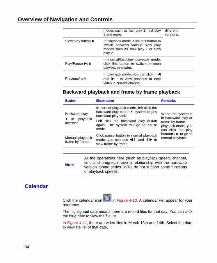
Calendar
Click the calendar icon in Figure 4-10. A calendar will appear for your reference.
The highlighted date means there are record files for that day. You can click the blue date to view the file list.
In Figure 4-11, there are video files in March 13th and 14th. Select the date to view file list of that date.
Honeywell
35
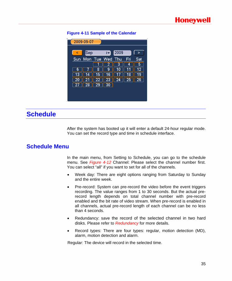
Figure 4-11 Sample of the Calendar
Schedule
After the system has booted up it will enter a default 24-hour regular mode. You can set the record type and time in schedule interface.
Schedule Menu
In the main menu, from Setting to Schedule, you can go to the schedule menu. See Figure 4-12 Channel: Please select the channel number first. You can select “all” if you want to set for all of the channels.
• Week day: There are eight options ranging from Saturday to Sunday and the entire week.
• Pre-record: System can pre-record the video before the event triggers recording. The value ranges from 1 to 30 seconds. But the actual pre-record length depends on total channel number with pre-record enabled and the bit rate of video stream. When pre-record is enabled in all channels, actual pre-record length of each channel can be no less than 4 seconds.
• Redundancy: save the record of the selected channel in two hard disks. Please refer to Redundancy for more details.
• Record types: There are four types: regular, motion detection (MD), alarm, motion detection and alarm.
Regular: The device will record in the selected time.
Overview of Navigation and Controls
36
MD: In the selected time, the device will record when MD happens, like motion diction, video loss, video mask.
Alarm: In the selected time, the device will record when there is alarm input.
MD & Alarm: In the selected time, the device will record when MD happens and at the same time there’s alarm input.
Note • Select MD and Alarm at the same time: when there is MD or
Alarm input the device will record in selected time period. • Select MD& Alarm: the device will record when MD and Alarm
input happen at the same time.
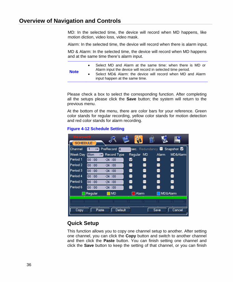
Please check a box to select the corresponding function. After completing all the setups please click the Save button; the system will return to the previous menu.
At the bottom of the menu, there are color bars for your reference. Green color stands for regular recording, yellow color stands for motion detection and red color stands for alarm recording.
Figure 4-12 Schedule Setting
Quick Setup This function allows you to copy one channel setup to another. After setting one channel, you can click the Copy button and switch to another channel and then click the Paste button. You can finish setting one channel and click the Save button to keep the setting of that channel, or you can finish

Honeywell
37
the entire setup and then click the Save button to keep all of the modified settings.
Redundancy Redundancy function allows you to save record file in several hard disks. When a record is damage in one disk, there is a spare one in the other disk, so that data reliability and safety is maintained.
In Main menu > Advanced > HDD Management, set one or more disk(s) as redundant from dropdown list. System automatically overwrites old files once hard disk is full.
Note At least one read-write disk is required for DVR to record video.
In Main menu > Setting > Schedule, check the Redundancy box to enable this function in the selected channel.
If current channel is not recording, the setup gets activated when the channel begin recording the next time.
If current channel is recording now, the setup will get activated immediately, and the current record will be terminated and a new file is created as redundancy recording is started.
After setup is completed, please click save button, system goes back to the previous menu.
Search and playback of the records in the redundant disk. There are two ways for you to playback or search in the redundant disk.
Set redundant disk(s) as read-only disk or read-write disk (Main menu->Advanced->HDD management). System needs to reboot to get setup activated. Now you can search or playback file in redundant disk.
Dismantle the disk and play it in another PC.
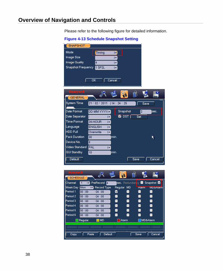
Snapshot
Schedule Snapshot In Encode interface, click snapshot button to input snapshot mode, size, quality and frequency.
In General interface please input upload interval.
In Schedule interface, please enable snapshot function.
Overview of Navigation and Controls
38
Please refer to the following figure for detailed information.
Figure 4-13 Schedule Snapshot Setting
Honeywell
39
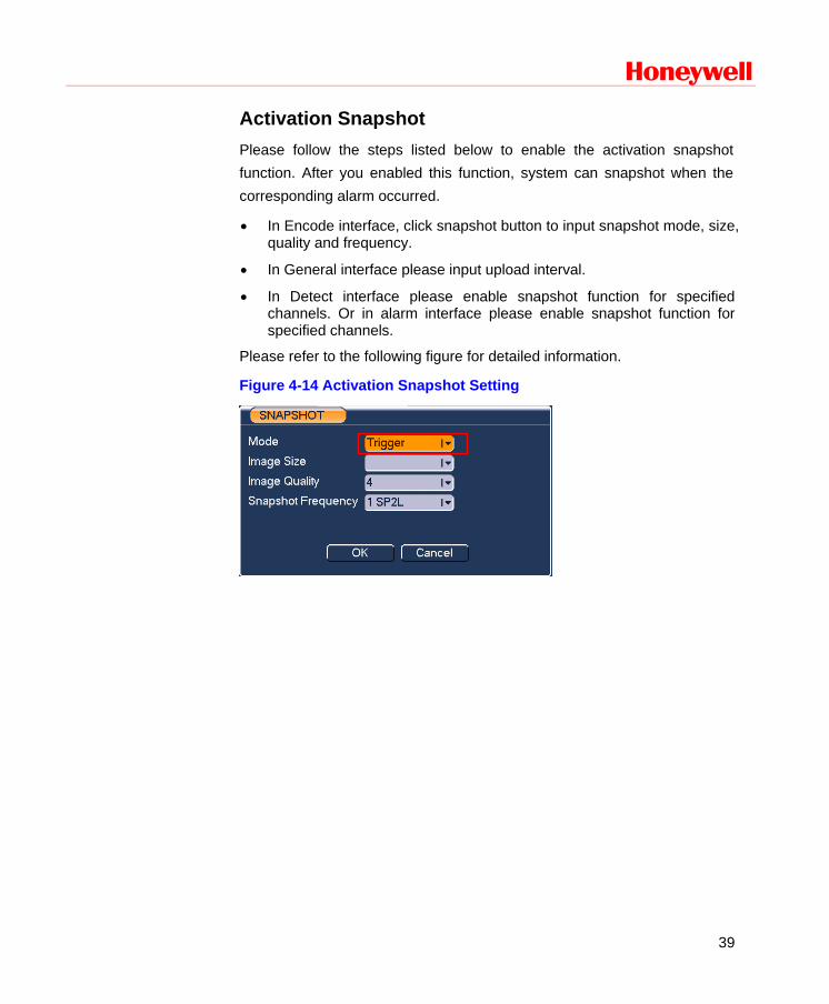
Activation Snapshot Please follow the steps listed below to enable the activation snapshot function. After you enabled this function, system can snapshot when the corresponding alarm occurred.
• In Encode interface, click snapshot button to input snapshot mode, size, quality and frequency.
• In General interface please input upload interval.
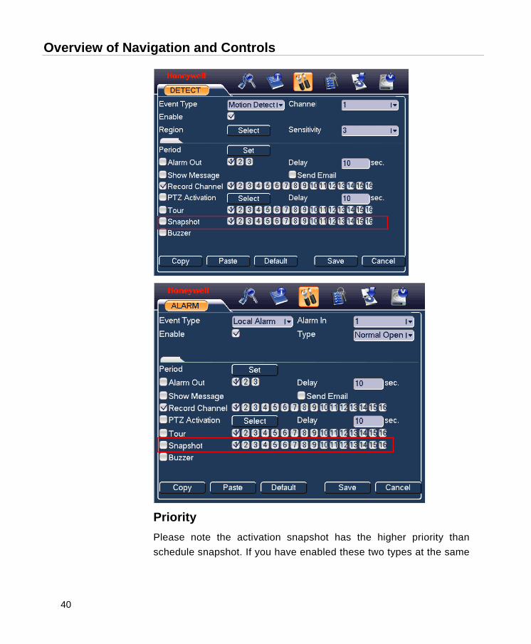
• In Detect interface please enable snapshot function for specified channels. Or in alarm interface please enable snapshot function for specified channels.
Please refer to the following figure for detailed information.
Figure 4-14 Activation Snapshot Setting
Overview of Navigation and Controls
40
Priority Please note the activation snapshot has the higher priority than schedule snapshot. If you have enabled these two types at the same

Honeywell
41
time, system can activate the activation snapshot when alarm occurs, and otherwise system just operates the schedule snapshot.
Image FTP
In Network interface, you can set FTP server information. Please enable FTP function and then click save button.
Please boot up corresponding FTP server.
Please enable schedule snapshot or activation snapshot first, now system can upload the image file to the FTP server.
After the system has booted up it will enter a default 24-hour regular mode. You can set the record type and time in schedule interface.
Detect
Go to Detect Menu
In the main menu, from Setting to Detect, you can see motion detect interface. There are three detection types: motion detection, video loss, camera masking.
Motion Detection
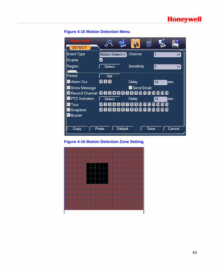
The detection menu is shown as below. See Figure 4-15.
• Event type: From the drop-down list you can select the “Motion Detection” type.
• Channel: Select the video channel for the motion detection setting.
• Record Channel: Select the channel to activate the recording function once the alarm has sounded. Please make sure you have set the MD recording in the schedule interface (Main MenuSettingSchedule) and automatic recording in manual record interface (Main Menu->Advanced->Manual Record)
Overview of Navigation and Controls
42
• Delay: When detected motion is completed, the system will continue alarm output and recording for a specified time respectively. The value ranges from 10-300(Unit: second).
• Region: Click Select, the interface is shown as in Figure 4-16. Here you can set the motion detection zone. There are 396(PAL)/330(NTSC) small zones.
• Sensitivity: The system supports 6 levels. The sixth level has the highest sensitivity. The fifth or lower levels are recommended to avoid setting a false alarm.
• Show message: The system will send message to the local host screen to alarm you if you have enabled this function.
• Send email: The system can send out an email to alert you when the alarm occurs.
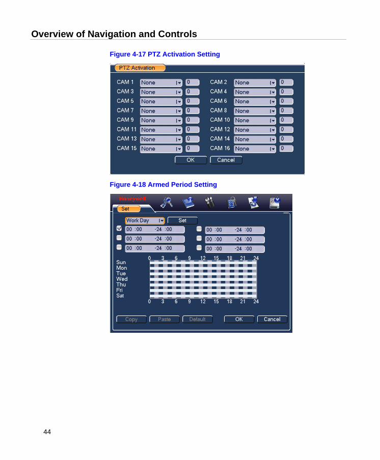
• PTZ activation: Here you can set PTZ movement (of any video channels) such as going to a preset when motion is detected in the current video channel. Click Select, and you can see an interface is shown as in Figure 4-17.
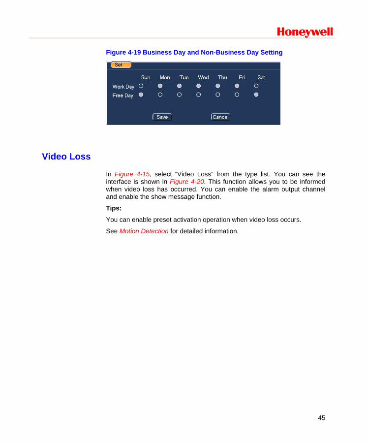
• Period: Click Set to determine the period for the channel to be armed for motion detection. See the interface shown as in Figure 4-18. Here you can set for business days and non-business days. In Figure 4-18, click Set, and you will see an interface as shown in Figure 4-19. Here you can set your own business day and non-business day.
• Alarm output: After the motion detection has occurred, the system enables the peripheral alarm devices.
• Tour: Here you can enable the tour function when the alarm occurs. It is a one-window tour. Please go to Display for tour interval setup.
Note If there are record channels selected, only the record channels will be displayed in the tour.
Check boxes to select the corresponding function. After all the settings, click Save, and the system will return to the previous menu.
Note
In Figure 4-16, you can left click the mouse and drag it to set a region for motion detection. Click Fn to switch between arm/withdraw motion detection. After setting the region, click the enter button to exit.
Honeywell
43
Figure 4-15 Motion Detection Menu
Figure 4-16 Motion Detection Zone Setting
Overview of Navigation and Controls
44
Figure 4-17 PTZ Activation Setting
Figure 4-18 Armed Period Setting
Honeywell
45
Figure 4-19 Business Day and Non-Business Day Setting
Video Loss
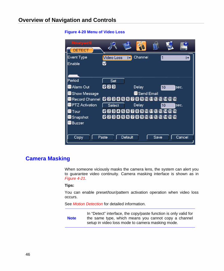
In Figure 4-15, select “Video Loss” from the type list. You can see the interface is shown in Figure 4-20. This function allows you to be informed when video loss has occurred. You can enable the alarm output channel and enable the show message function.
Tips:
You can enable preset activation operation when video loss occurs.
See Motion Detection for detailed information.
Overview of Navigation and Controls
46
Figure 4-20 Menu of Video Loss
Camera Masking
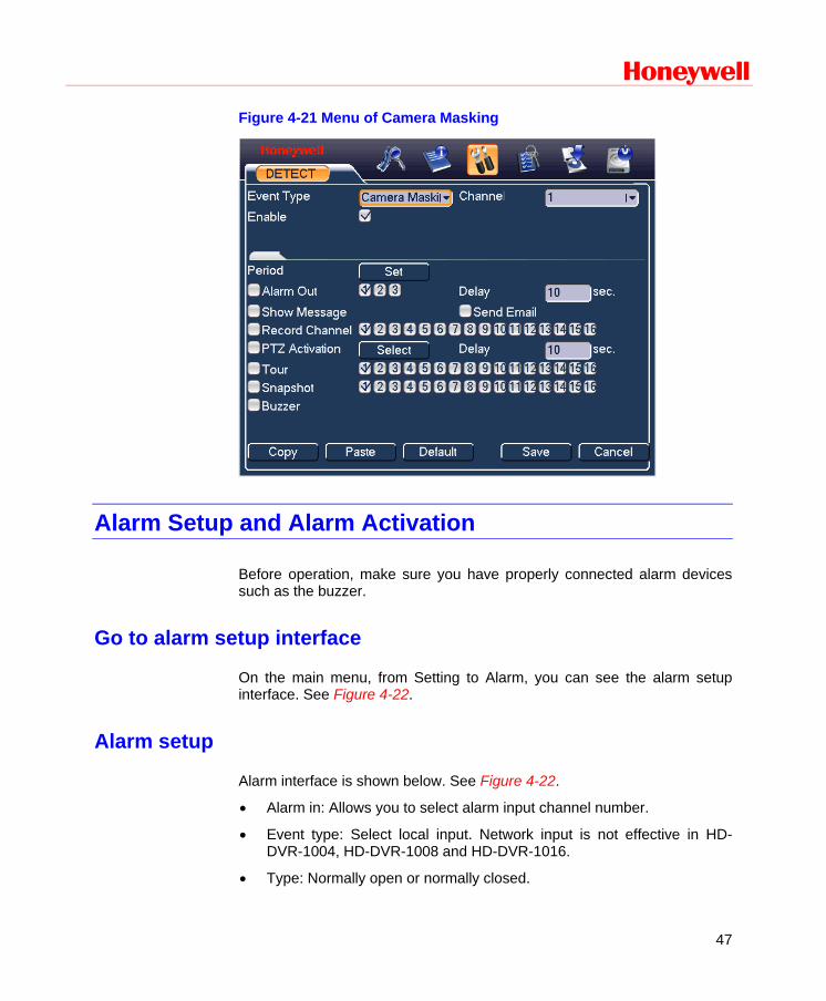
When someone viciously masks the camera lens, the system can alert you to guarantee video continuity. Camera masking interface is shown as in Figure 4-21.
Tips:
You can enable preset/tour/pattern activation operation when video loss occurs.
See Motion Detection for detailed information.
Note In “Detect” interface, the copy/paste function is only valid for the same type, which means you cannot copy a channel setup in video loss mode to camera masking mode.
Honeywell
47
Figure 4-21 Menu of Camera Masking
Alarm Setup and Alarm Activation
Before operation, make sure you have properly connected alarm devices such as the buzzer.
Go to alarm setup interface
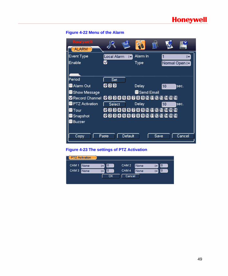
On the main menu, from Setting to Alarm, you can see the alarm setup interface. See Figure 4-22.
Alarm setup
Alarm interface is shown below. See Figure 4-22.
• Alarm in: Allows you to select alarm input channel number.
• Event type: Select local input. Network input is not effective in HD-DVR-1004, HD-DVR-1008 and HD-DVR-1016.
• Type: Normally open or normally closed.

Overview of Navigation and Controls
48
• PTZ activation: Here you can set PTZ movement when the alarm occurs. For example, go to preset, tour& pattern when there is an alarm. Click Select, and you can see an interface as shown in Figure 4-26.
• Period: Click Set, and you can see an interface as shown in Figure 4-24. Here you can set for business days and non-business days. In Figure 4-27, click Set, and you can see an interface shown in Figure 4-28. Here you can set your own setup for business days and non-business days.
• Show message: The system alert you on the local host screen if you enabled this function.
• Send email: The system can send out an email to alert you when an alarm occurs.
• Record channel: You can select the proper channel to record an alarm video (Multiple choices). At the same time you need to set alarm recording in the schedule interface (Main MenuSettingSchedule) and select the automatic record in manual record interface (Main MenuAdvanceManual Record).
• Alarm output: When the alarm sounds, the system enables the peripheral alarm devices.
• Delay: When the input alarm is completed, the system continues the alarm output and/or recording for a specified time respectively. The value ranges from 10-300(Unit: second)
• Tour: Here you can enable the tour function when the alarm occurs. It is a one-window tour; go to Display for the tour interval setup.
Note If there are record channels selected, only the record channels will be displayed in the tour.
Check boxes to select the corresponding function. After completing all the settings, click Save, and the system goes back to the previous menu.
Honeywell
49
Figure 4-22 Menu of the Alarm
Figure 4-23 The settings of PTZ Activation

Overview of Navigation and Controls
50
Figure 4-24 Period Setup
Figure 4-25 The Settings of Business Days and Non-Business Days
Backup
DVR supports various backup devices such as CD-RW, DVD driver, USB backup and network download. The records can be played with PC by the Record Player contained in the CD. Here we introduce USB backup first.
Note that the flash disk or portable HDD shall be FAT or FAT 32 file system.
Honeywell
51
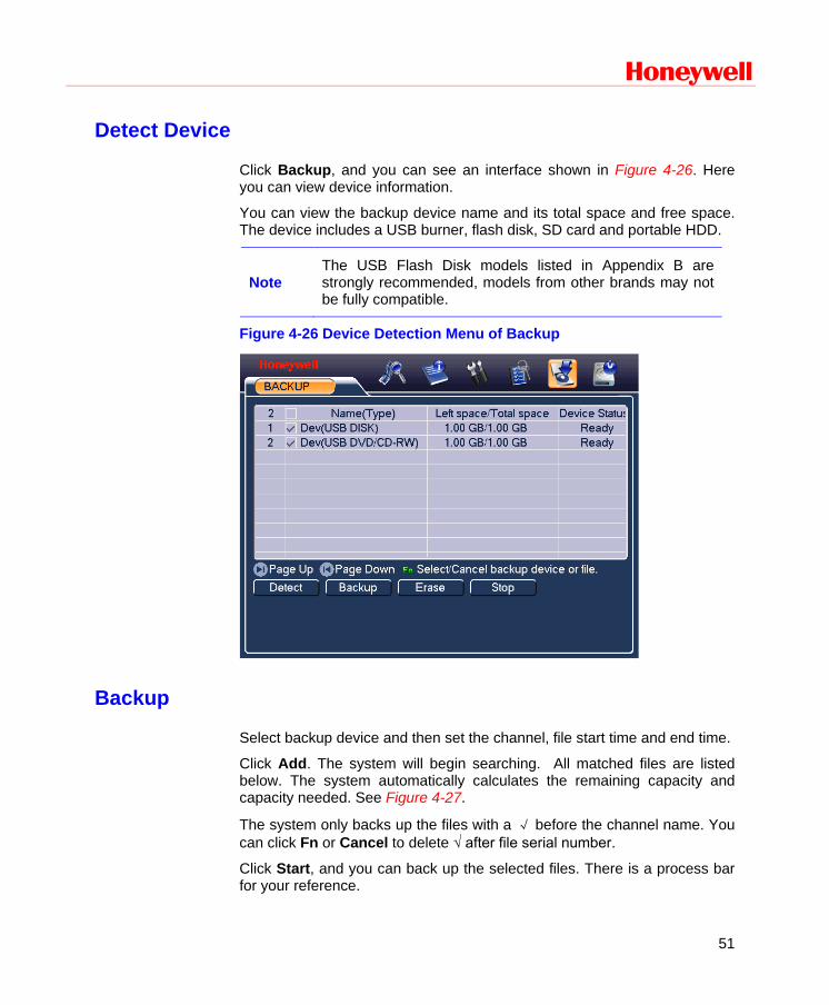
Detect Device
Click Backup, and you can see an interface shown in Figure 4-26. Here you can view device information.
You can view the backup device name and its total space and free space. The device includes a USB burner, flash disk, SD card and portable HDD.
Note The USB Flash Disk models listed in Appendix B are strongly recommended, models from other brands may not be fully compatible.
Figure 4-26 Device Detection Menu of Backup
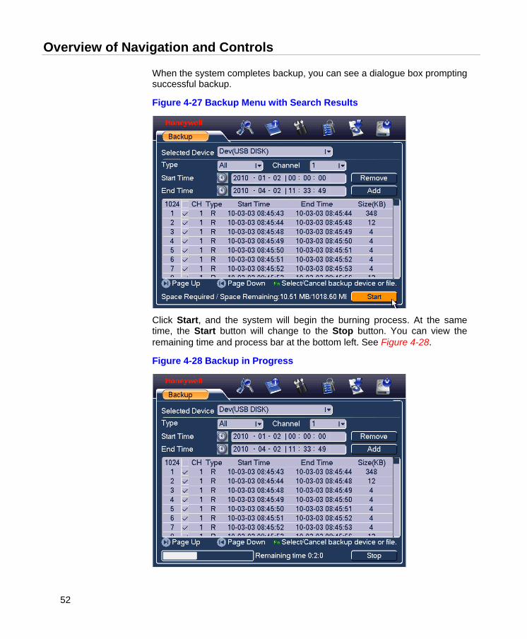
Backup
Select backup device and then set the channel, file start time and end time.
Click Add. The system will begin searching. All matched files are listed below. The system automatically calculates the remaining capacity and capacity needed. See Figure 4-27.
The system only backs up the files with a √ before the channel name. You can click Fn or Cancel to delete √ after file serial number.
Click Start, and you can back up the selected files. There is a process bar for your reference.
Overview of Navigation and Controls
52
When the system completes backup, you can see a dialogue box prompting successful backup.
Figure 4-27 Backup Menu with Search Results
Click Start, and the system will begin the burning process. At the same time, the Start button will change to the Stop button. You can view the remaining time and process bar at the bottom left. See Figure 4-28.
Figure 4-28 Backup in Progress

Honeywell
53
The file name format usually is: SN_CH+channel number+time Y+M+D+H+M+S. In the file name, the YDM format is the same as what you set in general interface (Main MenuSettingGeneral). The file extension name is “.dav”. You can visit our website to view listed CD-ROM brands.
Tips:
During the backup process, you can click ESC to exit the current interface for other operations. The system will not terminate the backup process.
Note When you click Stop during the burning process, backup will be stopped immediately, and some selected files may not be saved correctly in the device.
PTZ Control and Color Setup
Note
The operations described here are mainly based on PELCO-D protocol for Honeywell HSPT-120 speed dome. For other protocols, there might be a little difference.
Cable Connection
Please follow the procedures below to go on cable connection
• Connect the dome RS485 port to DVR 485 port.
• Connect the dome video output cable to DVR video input port.
• Connect the power adapter to the dome.
Overview of Navigation and Controls
54
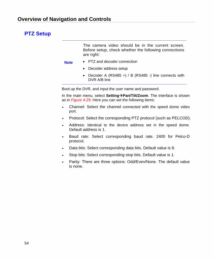
PTZ Setup
Note
The camera video should be in the current screen. Before setup, check whether the following connections are right:
• PTZ and decoder connection
• Decoder address setup
• Decoder A (RS485 +) / B (RS485 -) line connects with DVR A/B line
Boot up the DVR, and input the user name and password.
In the main menu, select SettingPan/Tilt/Zoom. The interface is shown as in Figure 4-29. Here you can set the following items:
• Channel: Select the channel connected with the speed dome video port.
• Protocol: Select the corresponding PTZ protocol (such as PELCOD).
• Address: Identical to the device address set in the speed dome. Default address is 1.
• Baud rate: Select corresponding baud rate. 2400 for Pelco-D protocol.
• Data bits: Select corresponding data bits. Default value is 8.
• Stop bits: Select corresponding stop bits. Default value is 1.
• Parity: There are three options: Odd/Even/None. The default value is none.

Honeywell
55
Figure 4-29 PTZ Setup Menu
After completing all the settings click Save.
In the single window display (View 1) mode, right-click to open the interface shown in Figure 4-30 (by clicking Fn in the front panel or in the remote controller will cause a menu to appear with only Pan/Tilt/Zoom and Color Setting options). .
Figure 4-30 The Context Menu
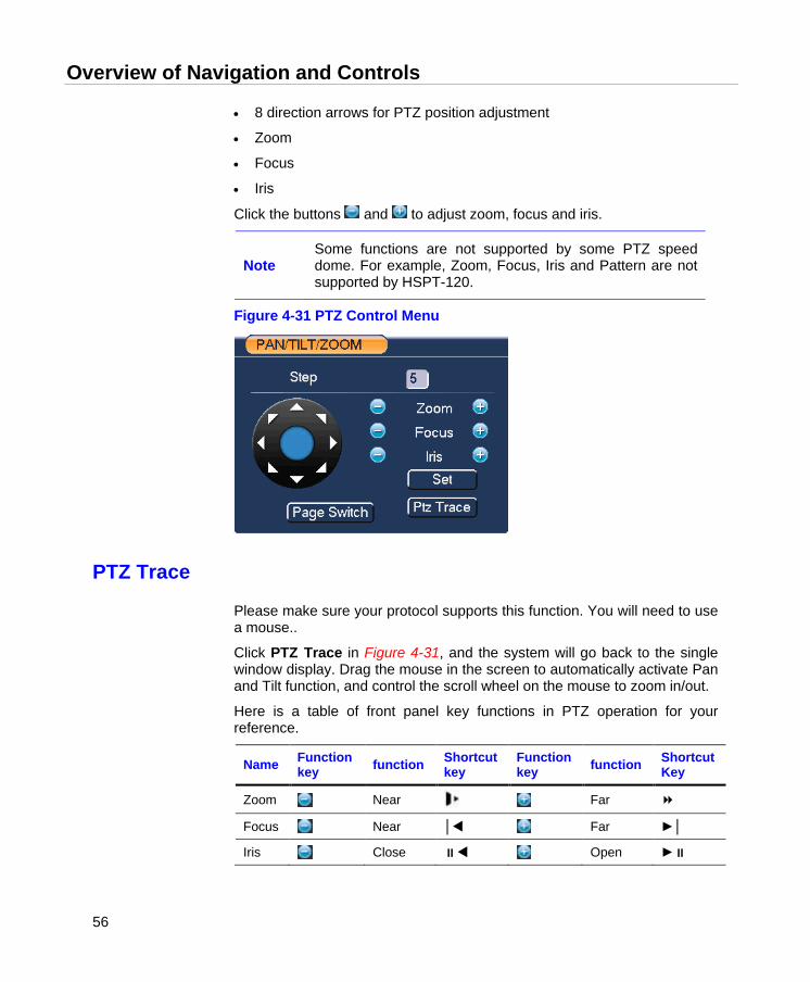
Click Pan/Tilt/Zoom, and the interface is shown as below. See Figure 4-31.
Here you can set the following items:
• Step: value ranges from 1 to 8.
Overview of Navigation and Controls
56
• 8 direction arrows for PTZ position adjustment
• Zoom
• Focus
• Iris
Click the buttons and to adjust zoom, focus and iris.
Note Some functions are not supported by some PTZ speed dome. For example, Zoom, Focus, Iris and Pattern are not supported by HSPT-120.
Figure 4-31 PTZ Control Menu
PTZ Trace
Please make sure your protocol supports this function. You will need to use a mouse..
Click PTZ Trace in Figure 4-31, and the system will go back to the single window display. Drag the mouse in the screen to automatically activate Pan and Tilt function, and control the scroll wheel on the mouse to zoom in/out.
Here is a table of front panel key functions in PTZ operation for your reference.
Name Function key function Shortcut
key Function key function Shortcut
Key
Zoom Near Far
Focus Near │ Far ►│
Iris Close Open ►
Honeywell
57
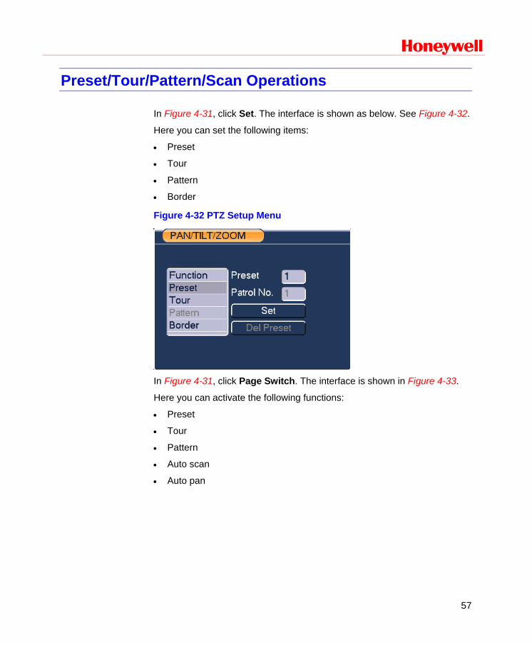
Preset/Tour/Pattern/Scan Operations
In Figure 4-31, click Set. The interface is shown as below. See Figure 4-32.
Here you can set the following items:
• Preset
• Tour
• Pattern
• Border
Figure 4-32 PTZ Setup Menu
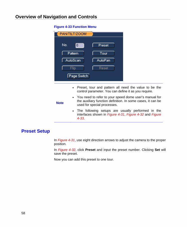
In Figure 4-31, click Page Switch. The interface is shown in Figure 4-33.
Here you can activate the following functions:
• Preset
• Tour
• Pattern
• Auto scan
• Auto pan
Overview of Navigation and Controls
58
Figure 4-33 Function Menu
Note
• Preset, tour and pattern all need the value to be the control parameter. You can define it as you require.
• You need to refer to your speed dome user’s manual for the auxiliary function definition. In some cases, it can be used for special processes.
• The following setups are usually performed in the interfaces shown in Figure 4-31, Figure 4-32 and Figure 4-33.
Preset Setup
In Figure 4-31, use eight direction arrows to adjust the camera to the proper position.
In Figure 4-32, click Preset and input the preset number. Clicking Set will save the preset.
Now you can add this preset to one tour.

Honeywell
59
Figure 4-34 Preset Setup
Activate Preset
In Figure 4-33, input the preset number in the “No.” field, and click Preset.
Patrol setup (Tour Setup)
In Figure 4-32, click Patrol. The interface is shown in Figure 4-35. Input the preset number and add this preset to a patrol (tour). For each patrol (tour), you can input 80 presets at most.
Figure 4-35 Tour Setup
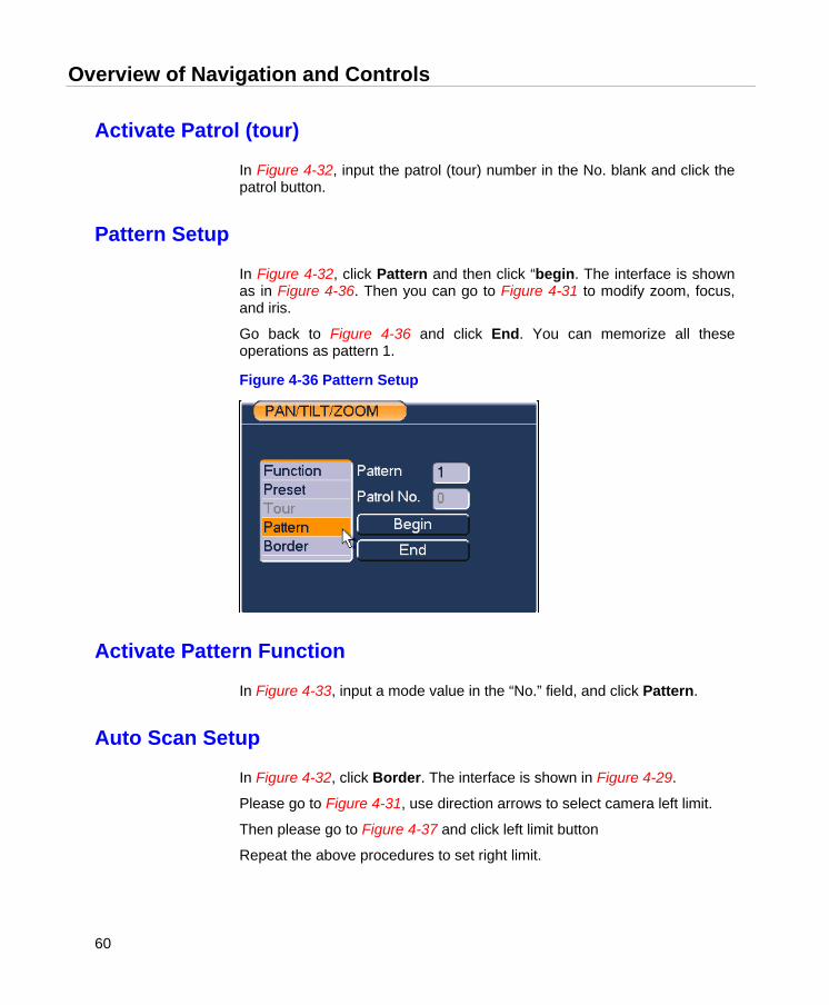
Overview of Navigation and Controls
60
Activate Patrol (tour)
In Figure 4-32, input the patrol (tour) number in the No. blank and click the patrol button.
Pattern Setup
In Figure 4-32, click Pattern and then click “begin. The interface is shown as in Figure 4-36. Then you can go to Figure 4-31 to modify zoom, focus, and iris.
Go back to Figure 4-36 and click End. You can memorize all these operations as pattern 1.
Figure 4-36 Pattern Setup
Activate Pattern Function
In Figure 4-33, input a mode value in the “No.” field, and click Pattern.
Auto Scan Setup
In Figure 4-32, click Border. The interface is shown in Figure 4-29.
Please go to Figure 4-31, use direction arrows to select camera left limit.
Then please go to Figure 4-37 and click left limit button
Repeat the above procedures to set right limit.
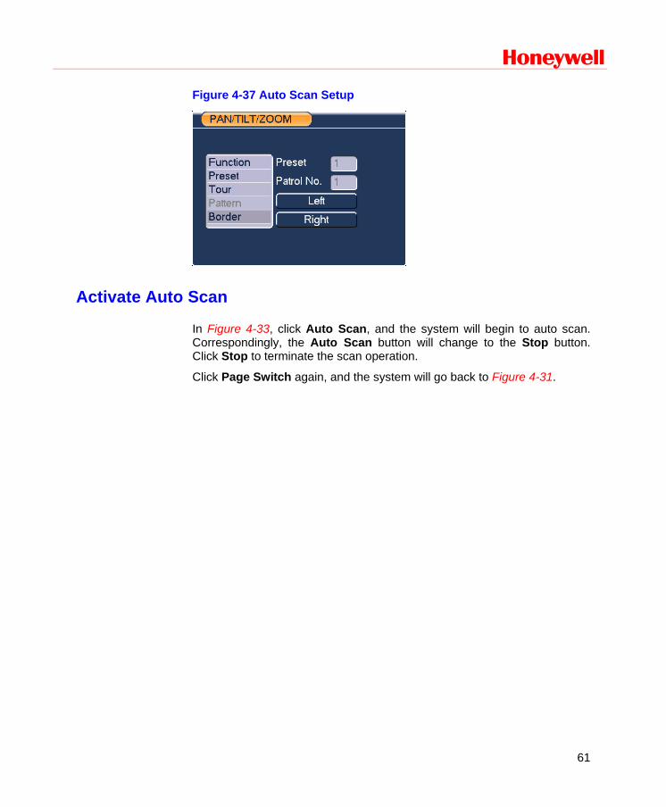
Honeywell
61
Figure 4-37 Auto Scan Setup
Activate Auto Scan
In Figure 4-33, click Auto Scan, and the system will begin to auto scan. Correspondingly, the Auto Scan button will change to the Stop button. Click Stop to terminate the scan operation.
Click Page Switch again, and the system will go back to Figure 4-31.
Understanding of Menu Operations and Controls
62
5 Understanding of Menu Operations and Controls
Menu Tree
This series DVR menu tree is shown as below:
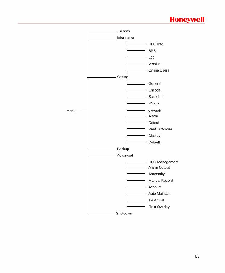
Honeywell
63
Search
Information
HDD Info
BPS
Log
Version
Online Users
Setting
General
Encode
Schedule
RS232
Menu Network Alarm
Detect
Pan/ Tilt/Zoom
Display
Default
Backup
Advanced
HDD Management Alarm Output
Abnormity
Manual Record
Account
Auto Maintain
TV Adjust
Text Overlay
Shutdown

Understanding of Menu Operations and Controls
64
Main Menu
After you have logged in, the system main menu will appear as shown below. See Figure 5-1. There are a total of six buttons: Search, Info, Setting, Backup, Advanced, and Shutdown. Move the cursor to highlight the icon, and then double-click to enter the sub-menu.
Figure 5-1 The Main Menu – Setting
Setting
In the main menu, highlight the setting icon and double-click the mouse. The system setting interface is shown below.
General
General setting includes the following items. See Figure 5-2.
• System time: Here is for you to set system time
• Date format: There are three types: YYYYY-MM-DD: MM-DD-YYYYY or DD-MM-YYYY.
• Date separator: There are three denotations to separate the date: dot, beeline and solidus.
Honeywell
65
• DST: Here you can set DST time and date. Please enable DST function and then click set button. You can see an interface is shown as in Figure 5-3. Here you can set start time and end time by setting corresponding week setup. In Figure 5-3, enable date button, you can see an interface is shown as in Figure 5-4. Here you can set start time and end time by setting corresponding date setup.
• Time format: There are two types: 24-hour mode or 12-hour mode.
• Language: System supports various languages: Chinese (simplified), Chinese (Traditional), English, Italian, Japanese, French, Spanish (All languages listed here are optional. Slight difference may be found in various series.)
• HDD full: Here you can select the working mode when the hard disk is full. There are two options: Stop recording or overwrite.
• Pack duration: Here is for you to specify the maximum length of each record file from 1 to 120 minutes. Default value is 60 minutes. The change will take effect in the new record file.
• DVR No: When you are using one remote control to control several DVRs, you can give a name to each DVR for your management.
• Video standard: There are two formats: NTSC and PAL.
• Auto logout: Here is for you to set auto logout interval once login user remains inactive for a specified time. Value ranges from 0 to 60 minutes.
Note
• Since system time is very important, do not modify time casually unless there is a must!
• Before your time modification, please stop record operation first!
After completing all the setups click Save. The system will return to the previous menu.
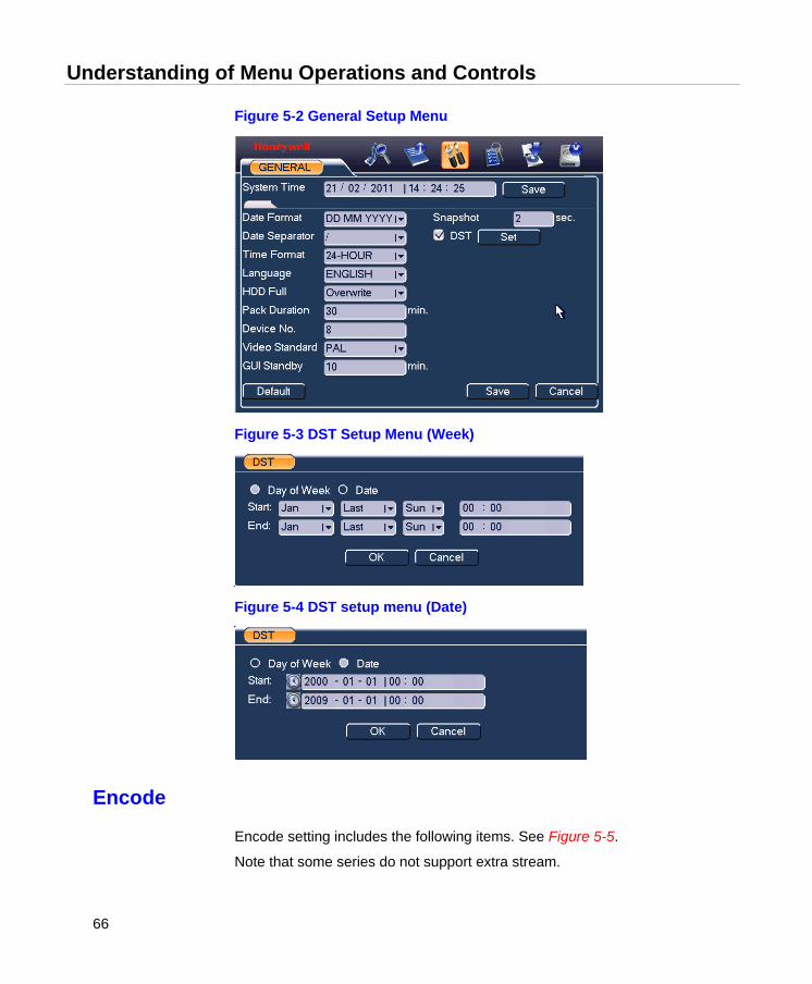
Understanding of Menu Operations and Controls
66
Figure 5-2 General Setup Menu
Figure 5-3 DST Setup Menu (Week)
Figure 5-4 DST setup menu (Date)
Encode
Encode setting includes the following items. See Figure 5-5.
Note that some series do not support extra stream.
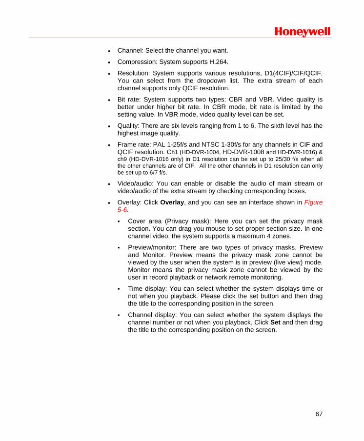
Honeywell
67
• Channel: Select the channel you want.
• Compression: System supports H.264.
• Resolution: System supports various resolutions, D1(4CIF)/CIF/QCIF. You can select from the dropdown list. The extra stream of each channel supports only QCIF resolution.
• Bit rate: System supports two types: CBR and VBR. Video quality is better under higher bit rate. In CBR mode, bit rate is limited by the setting value. In VBR mode, video quality level can be set.
• Quality: There are six levels ranging from 1 to 6. The sixth level has the highest image quality.
• Frame rate: PAL 1-25f/s and NTSC 1-30f/s for any channels in CIF and QCIF resolution. Ch1 (HD-DVR-1004, HD-DVR-1008 and HD-DVR-1016) & ch9 (HD-DVR-1016 only) in D1 resolution can be set up to 25/30 f/s when all the other channels are of CIF. All the other channels in D1 resolution can only be set up to 6/7 f/s.
• Video/audio: You can enable or disable the audio of main stream or video/audio of the extra stream by checking corresponding boxes.
• Overlay: Click Overlay, and you can see an interface shown in Figure 5-6.
Cover area (Privacy mask): Here you can set the privacy mask section. You can drag you mouse to set proper section size. In one channel video, the system supports a maximum 4 zones.
Preview/monitor: There are two types of privacy masks. Preview and Monitor. Preview means the privacy mask zone cannot be viewed by the user when the system is in preview (live view) mode. Monitor means the privacy mask zone cannot be viewed by the user in record playback or network remote monitoring.
Time display: You can select whether the system displays time or not when you playback. Please click the set button and then drag the title to the corresponding position in the screen.
Channel display: You can select whether the system displays the channel number or not when you playback. Click Set and then drag the title to the corresponding position on the screen.
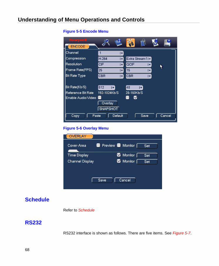
Understanding of Menu Operations and Controls
68
Figure 5-5 Encode Menu
Figure 5-6 Overlay Menu
Schedule
Refer to Schedule
RS232
RS232 interface is shown as follows. There are five items. See Figure 5-7.
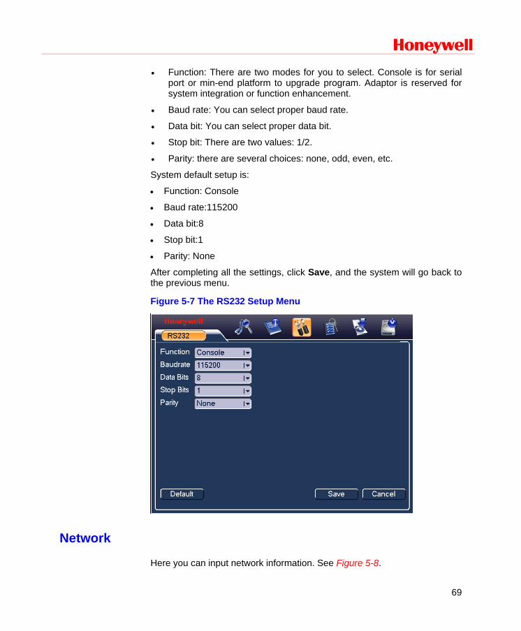
Honeywell
69
• Function: There are two modes for you to select. Console is for serial port or min-end platform to upgrade program. Adaptor is reserved for system integration or function enhancement.
• Baud rate: You can select proper baud rate.
• Data bit: You can select proper data bit.
• Stop bit: There are two values: 1/2.
• Parity: there are several choices: none, odd, even, etc.
System default setup is:
• Function: Console
• Baud rate:115200
• Data bit:8
• Stop bit:1
• Parity: None
After completing all the settings, click Save, and the system will go back to the previous menu.
Figure 5-7 The RS232 Setup Menu
Network
Here you can input network information. See Figure 5-8.
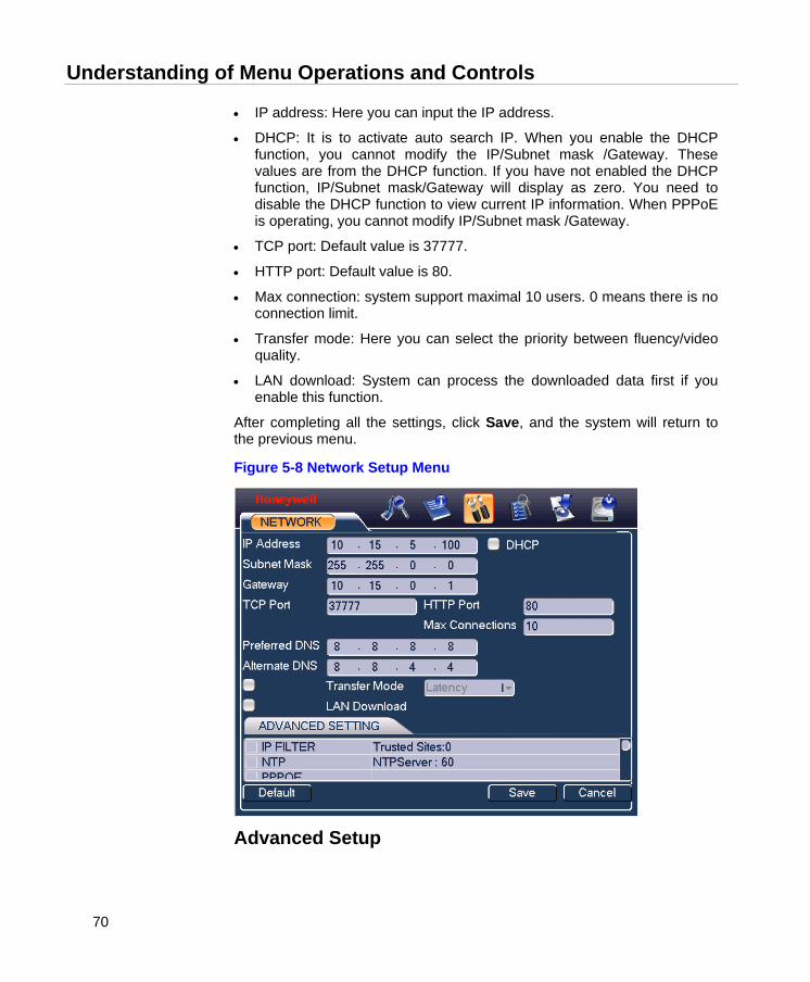
Understanding of Menu Operations and Controls
70
• IP address: Here you can input the IP address.
• DHCP: It is to activate auto search IP. When you enable the DHCP function, you cannot modify the IP/Subnet mask /Gateway. These values are from the DHCP function. If you have not enabled the DHCP function, IP/Subnet mask/Gateway will display as zero. You need to disable the DHCP function to view current IP information. When PPPoE is operating, you cannot modify IP/Subnet mask /Gateway.
• TCP port: Default value is 37777.
• HTTP port: Default value is 80.
• Max connection: system support maximal 10 users. 0 means there is no connection limit.
• Transfer mode: Here you can select the priority between fluency/video quality.
• LAN download: System can process the downloaded data first if you enable this function.
After completing all the settings, click Save, and the system will return to the previous menu.
Figure 5-8 Network Setup Menu
Advanced Setup

Honeywell
71
Advanced setup interface is shown in Figure 5-9. Draw a circle to enable the corresponding function and then double-click the current item to go to the setup interface.
Figure 5-9 Advanced Settings
IP Filter IP filter interface is shown in Figure 5-10. You can add IP in the following list. The list supports a max of 64 IP addresses.
Note that after you enable this function, only the IP listed below can access current DVR.
If you disable this function, all IP addresses can access the current DVR.
Figure 5-10 IP Filter Menu
Multiple Cast Here you can set a multiple cast group. Please refer to the following sheet for detailed information.

Understanding of Menu Operations and Controls
72
· IP multiple cast group address
-224.0.0.0-239.255.255.255
-“D” address space
· The higher four-bit of the first byte=”1110”
· Reserved local multiple cast group address
-224.0.0.0-224.0.0.255
-TTL=1 When sending out telegraph
-For example
224.0.0.1 All systems in the sub-net
224.0.0.2 All routers in the sub-net
224.0.0.4 DVMRP router
224.0.0.5 OSPF router
224.0.0.13 PIMv2 router
· Administrative scoped addressees
-239.0.0.0-239.255.255.255
-Private address space
· Like the single broadcast address of RFC1918
· Cannot be used in Internet transmission
· Used for multiple cast broadcast in limited space
Except the above mentioned addresses of special meaning, you can use other addresses. For example:
Multiple cast IP: 235.8.8.36
Multiple cast PORT: 3666
After you logged in the Web, the Web can automatically get multiple cast address and add it to the multiple cast groups. You can enable real-time monitor function to view the view.
Please note multiple cast function applies to special series only.
PPPoE PPPoE interface is shown in Figure 5-11.
Input “PPPoE name” and “PPPoE password” you receive from your ISP (Internet service provider).
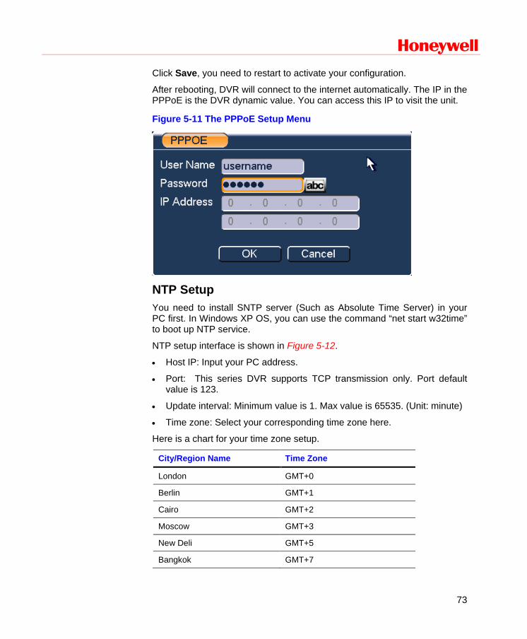
Honeywell
73
Click Save, you need to restart to activate your configuration.
After rebooting, DVR will connect to the internet automatically. The IP in the PPPoE is the DVR dynamic value. You can access this IP to visit the unit.
Figure 5-11 The PPPoE Setup Menu
NTP Setup You need to install SNTP server (Such as Absolute Time Server) in your PC first. In Windows XP OS, you can use the command “net start w32time” to boot up NTP service.
NTP setup interface is shown in Figure 5-12.
• Host IP: Input your PC address.
• Port: This series DVR supports TCP transmission only. Port default value is 123.
• Update interval: Minimum value is 1. Max value is 65535. (Unit: minute)
• Time zone: Select your corresponding time zone here.
Here is a chart for your time zone setup.
City/Region Name Time Zone
London GMT+0
Berlin GMT+1
Cairo GMT+2
Moscow GMT+3
New Deli GMT+5
Bangkok GMT+7
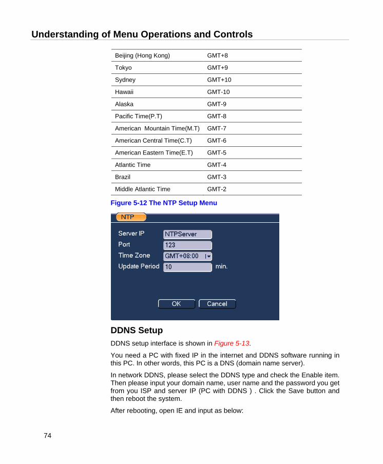
Understanding of Menu Operations and Controls
74
Beijing (Hong Kong) GMT+8
Tokyo GMT+9
Sydney GMT+10
Hawaii GMT-10
Alaska GMT-9
Pacific Time(P.T) GMT-8
American Mountain Time(M.T) GMT-7
American Central Time(C.T) GMT-6
American Eastern Time(E.T) GMT-5
Atlantic Time GMT-4
Brazil GMT-3
Middle Atlantic Time GMT-2
Figure 5-12 The NTP Setup Menu
DDNS Setup DDNS setup interface is shown in Figure 5-13.
You need a PC with fixed IP in the internet and DDNS software running in this PC. In other words, this PC is a DNS (domain name server).
In network DDNS, please select the DDNS type and check the Enable item. Then please input your domain name, user name and the password you get from you ISP and server IP (PC with DDNS ) . Click the Save button and then reboot the system.
After rebooting, open IE and input as below:
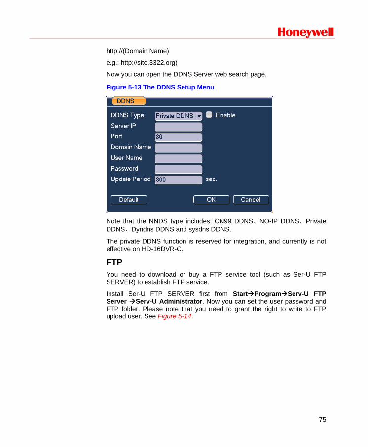
Honeywell
75
http://(Domain Name)
e.g.: http://site.3322.org)
Now you can open the DDNS Server web search page.
Figure 5-13 The DDNS Setup Menu
Note that the NNDS type includes: CN99 DDNS、NO-IP DDNS、Private DDNS、Dyndns DDNS and sysdns DDNS.
The private DDNS function is reserved for integration, and currently is not effective on HD-16DVR-C.
FTP You need to download or buy a FTP service tool (such as Ser-U FTP SERVER) to establish FTP service.
Install Ser-U FTP SERVER first from StartProgramServ-U FTP Server Serv-U Administrator. Now you can set the user password and FTP folder. Please note that you need to grant the right to write to FTP upload user. See Figure 5-14.
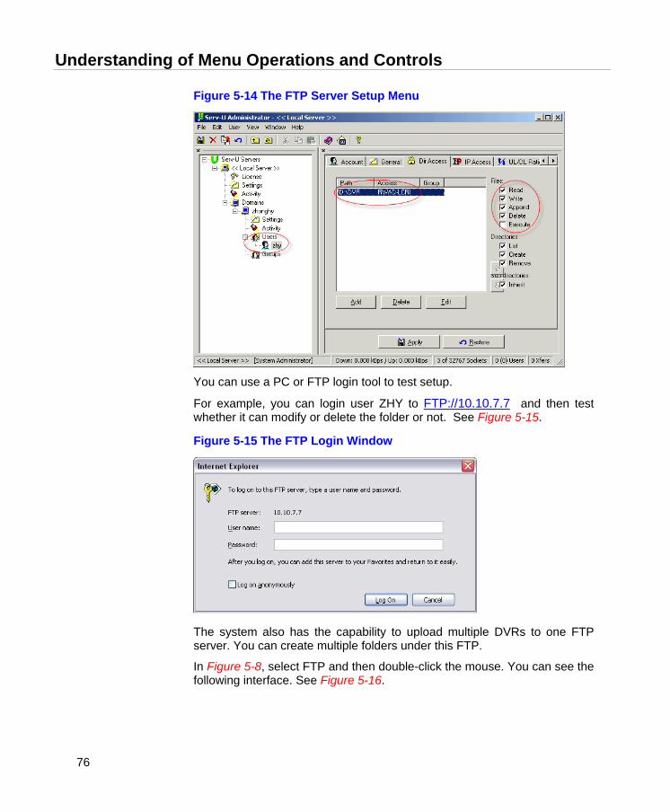
Understanding of Menu Operations and Controls
76
Figure 5-14 The FTP Server Setup Menu
You can use a PC or FTP login tool to test setup.
For example, you can login user ZHY to FTP://10.10.7.7 and then test whether it can modify or delete the folder or not. See Figure 5-15.
Figure 5-15 The FTP Login Window
The system also has the capability to upload multiple DVRs to one FTP server. You can create multiple folders under this FTP.
In Figure 5-8, select FTP and then double-click the mouse. You can see the following interface. See Figure 5-16.
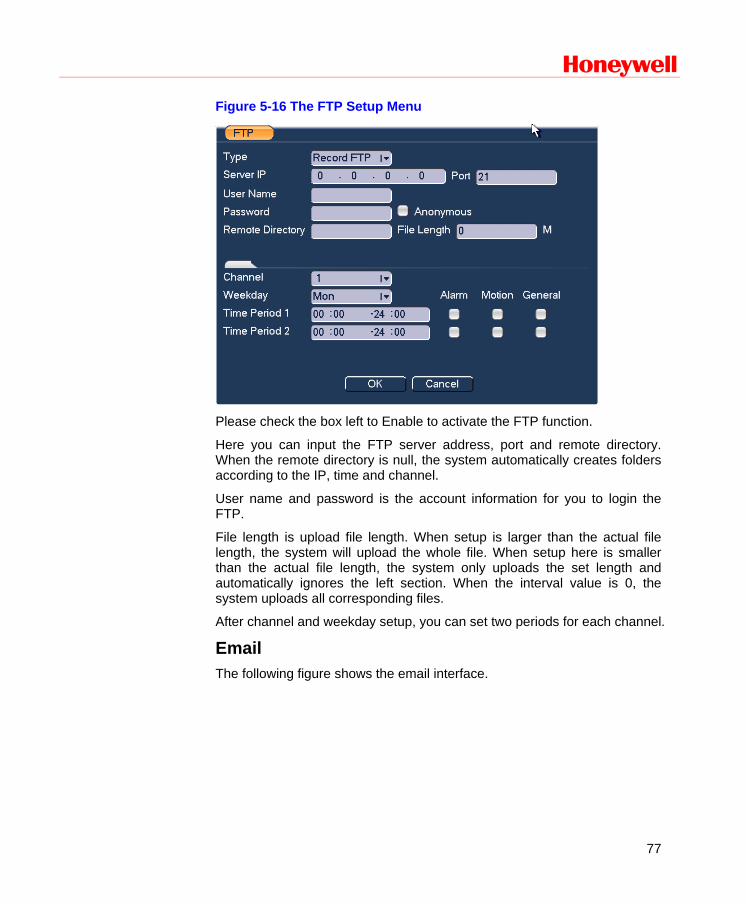
Honeywell
77
Figure 5-16 The FTP Setup Menu
Please check the box left to Enable to activate the FTP function.
Here you can input the FTP server address, port and remote directory. When the remote directory is null, the system automatically creates folders according to the IP, time and channel.
User name and password is the account information for you to login the FTP.
File length is upload file length. When setup is larger than the actual file length, the system will upload the whole file. When setup here is smaller than the actual file length, the system only uploads the set length and automatically ignores the left section. When the interval value is 0, the system uploads all corresponding files.
After channel and weekday setup, you can set two periods for each channel.
Email The following figure shows the email interface.
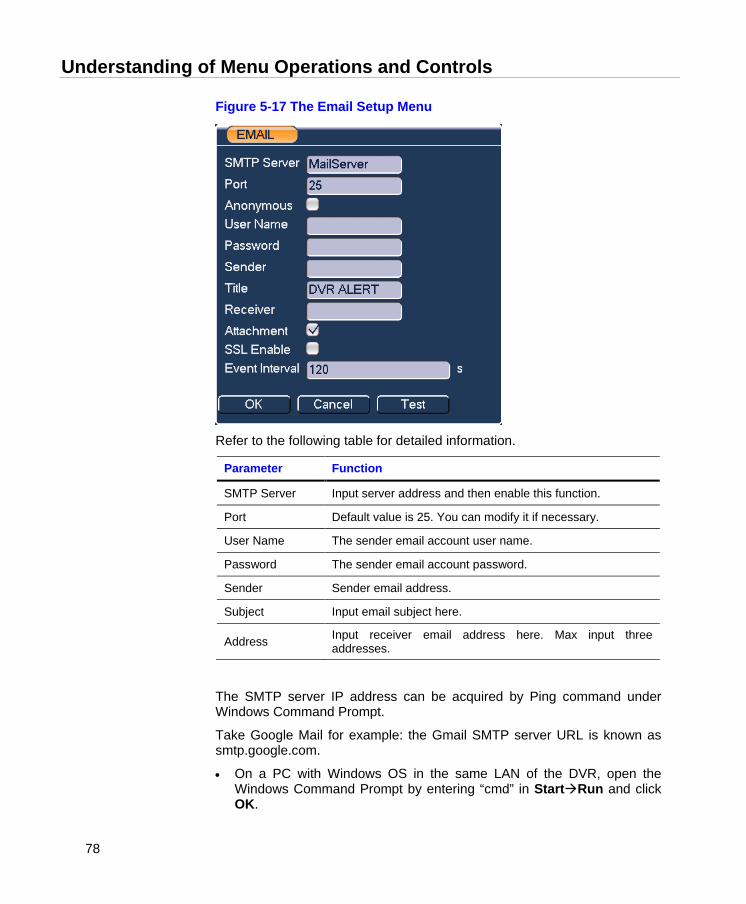
Understanding of Menu Operations and Controls
78
Figure 5-17 The Email Setup Menu
Refer to the following table for detailed information.
Parameter Function
SMTP Server Input server address and then enable this function.
Port Default value is 25. You can modify it if necessary.
User Name The sender email account user name.
Password The sender email account password.
Sender Sender email address.
Subject Input email subject here.
Address Input receiver email address here. Max input three addresses.
The SMTP server IP address can be acquired by Ping command under Windows Command Prompt.
Take Google Mail for example: the Gmail SMTP server URL is known as smtp.google.com.
• On a PC with Windows OS in the same LAN of the DVR, open the Windows Command Prompt by entering “cmd” in StartRun and click OK.
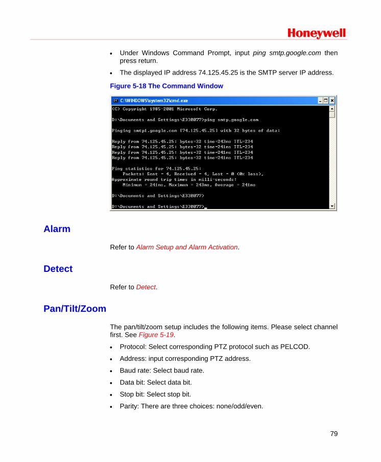
Honeywell
79
• Under Windows Command Prompt, input ping smtp.google.com then press return.
• The displayed IP address 74.125.45.25 is the SMTP server IP address.
Figure 5-18 The Command Window
Alarm
Refer to Alarm Setup and Alarm Activation.
Detect
Refer to Detect.
Pan/Tilt/Zoom
The pan/tilt/zoom setup includes the following items. Please select channel first. See Figure 5-19.
• Protocol: Select corresponding PTZ protocol such as PELCOD.
• Address: input corresponding PTZ address.
• Baud rate: Select baud rate.
• Data bit: Select data bit.
• Stop bit: Select stop bit.
• Parity: There are three choices: none/odd/even.
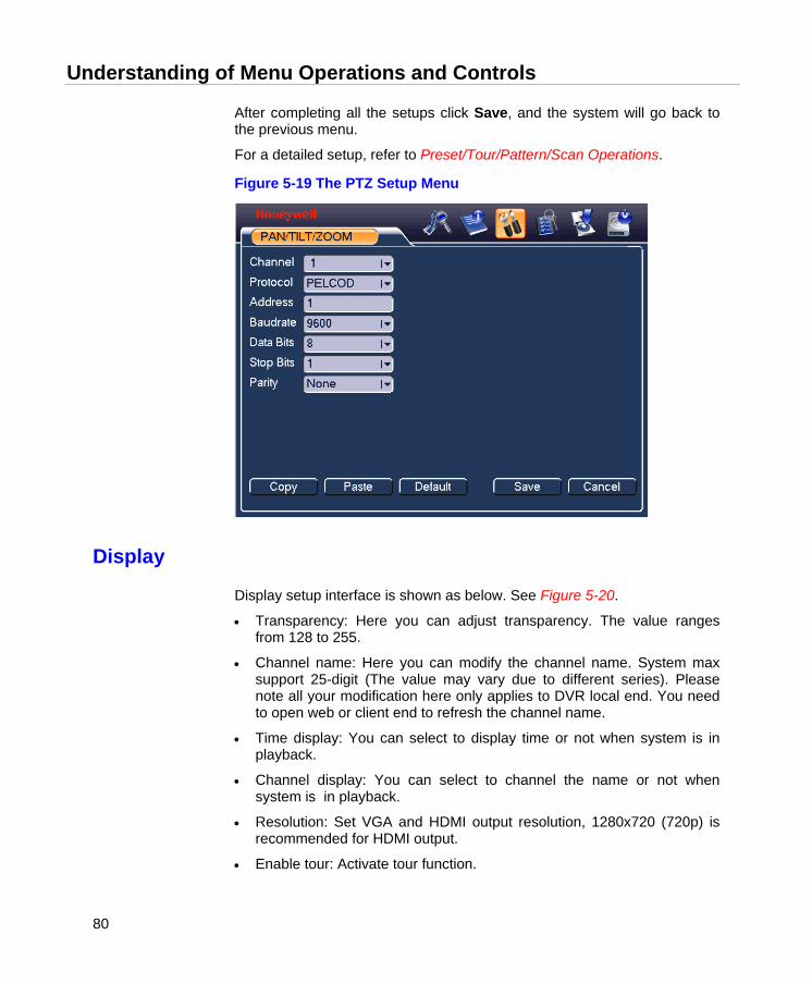
Understanding of Menu Operations and Controls
80
After completing all the setups click Save, and the system will go back to the previous menu.
For a detailed setup, refer to Preset/Tour/Pattern/Scan Operations.
Figure 5-19 The PTZ Setup Menu
Display
Display setup interface is shown as below. See Figure 5-20.
• Transparency: Here you can adjust transparency. The value ranges from 128 to 255.
• Channel name: Here you can modify the channel name. System max support 25-digit (The value may vary due to different series). Please note all your modification here only applies to DVR local end. You need to open web or client end to refresh the channel name.
• Time display: You can select to display time or not when system is in playback.
• Channel display: You can select to channel the name or not when system is in playback.
• Resolution: Set VGA and HDMI output resolution, 1280x720 (720p) is recommended for HDMI output.
• Enable tour: Activate tour function.
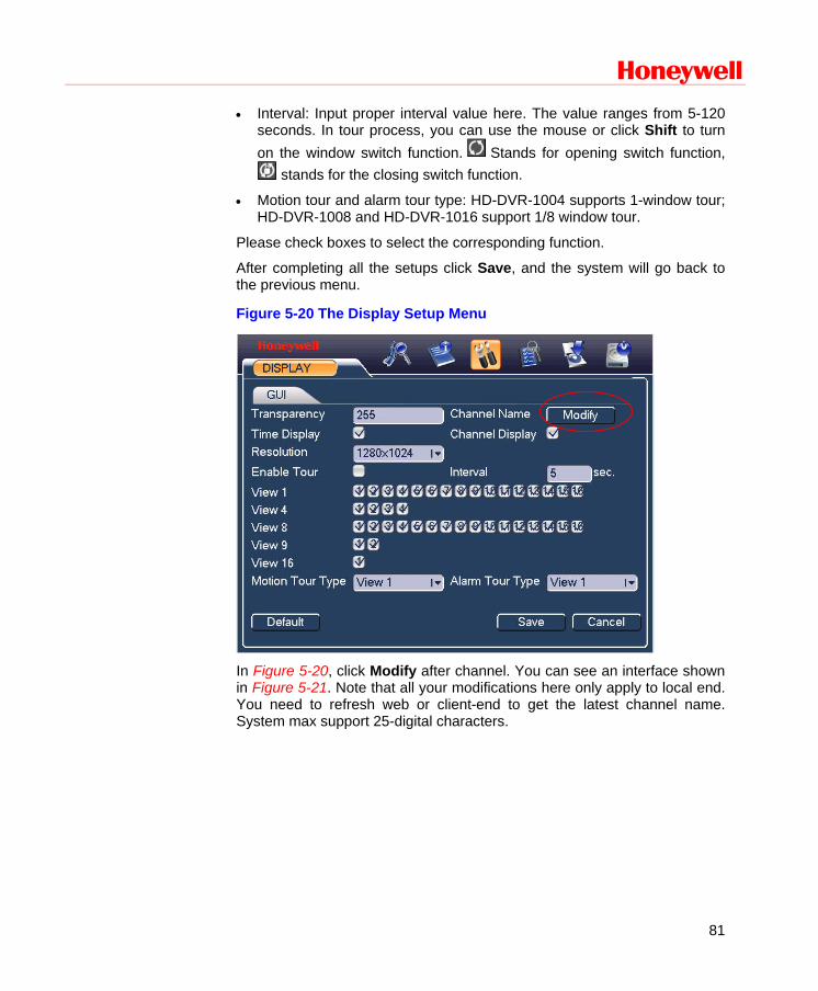
Honeywell
81
• Interval: Input proper interval value here. The value ranges from 5-120 seconds. In tour process, you can use the mouse or click Shift to turn on the window switch function. Stands for opening switch function,
stands for the closing switch function.
• Motion tour and alarm tour type: HD-DVR-1004 supports 1-window tour; HD-DVR-1008 and HD-DVR-1016 support 1/8 window tour.
Please check boxes to select the corresponding function.
After completing all the setups click Save, and the system will go back to the previous menu.
Figure 5-20 The Display Setup Menu
In Figure 5-20, click Modify after channel. You can see an interface shown in Figure 5-21. Note that all your modifications here only apply to local end. You need to refresh web or client-end to get the latest channel name. System max support 25-digital characters.
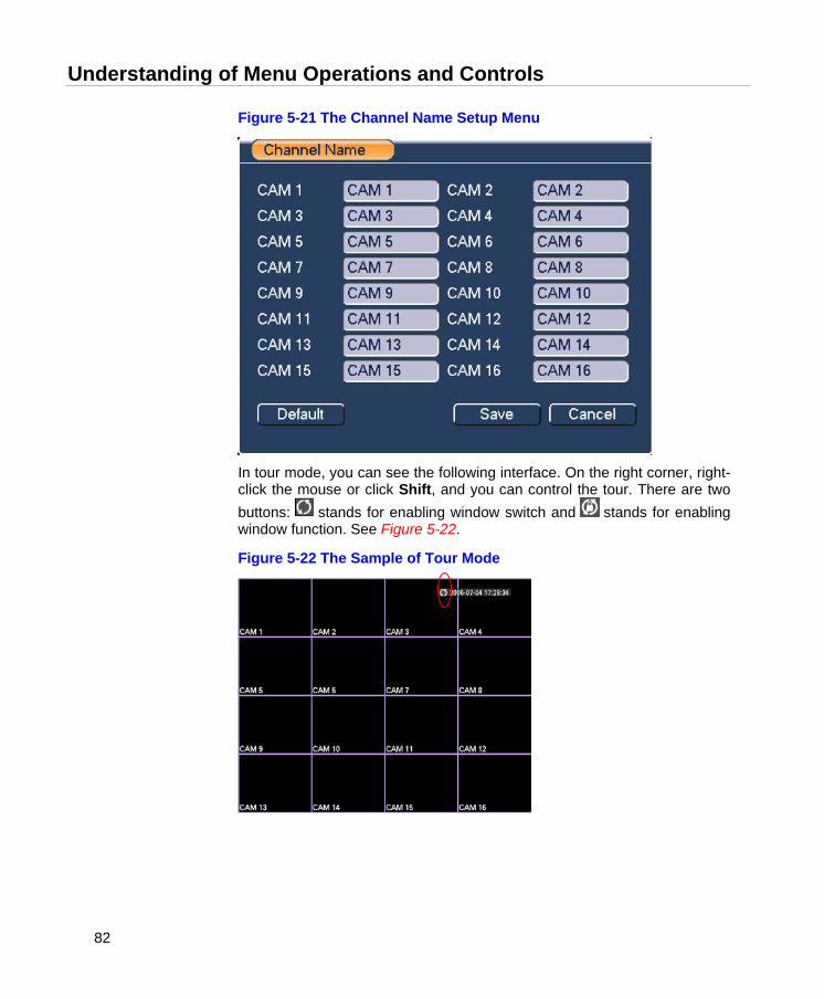
Understanding of Menu Operations and Controls
82
Figure 5-21 The Channel Name Setup Menu
In tour mode, you can see the following interface. On the right corner, right-click the mouse or click Shift, and you can control the tour. There are two buttons: stands for enabling window switch and stands for enabling window function. See Figure 5-22.
Figure 5-22 The Sample of Tour Mode
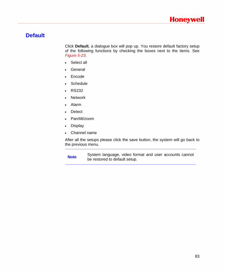
Honeywell
83
Default
Click Default, a dialogue box will pop up. You restore default factory setup of the following functions by checking the boxes next to the items. See Figure 5-23.
• Select all
• General
• Encode
• Schedule
• RS232
• Network
• Alarm
• Detect
• Pan/tilt/zoom
• Display
• Channel name
After all the setups please click the save button, the system will go back to the previous menu.
Note System language, video format and user accounts cannot be restored to default setup.
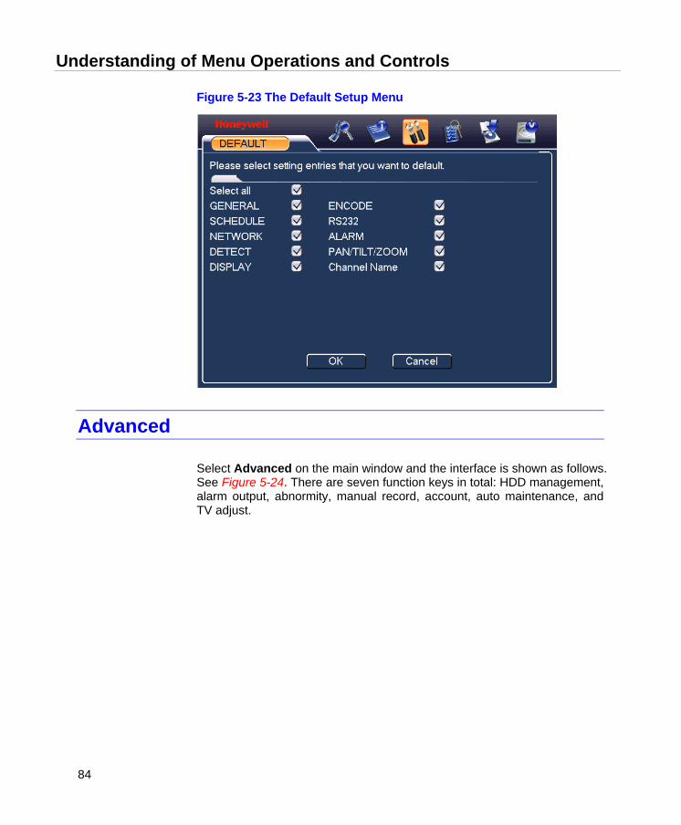
Understanding of Menu Operations and Controls
84
Figure 5-23 The Default Setup Menu
Advanced
Select Advanced on the main window and the interface is shown as follows. See Figure 5-24. There are seven function keys in total: HDD management, alarm output, abnormity, manual record, account, auto maintenance, and TV adjust.
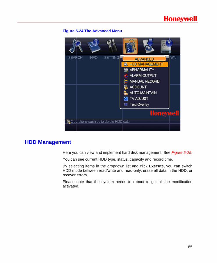
Honeywell
85
Figure 5-24 The Advanced Menu
HDD Management
Here you can view and implement hard disk management. See Figure 5-25.
You can see current HDD type, status, capacity and record time.
By selecting items in the dropdown list and click Execute, you can switch HDD mode between read/write and read-only, erase all data in the HDD, or recover errors.
Please note that the system needs to reboot to get all the modification activated.
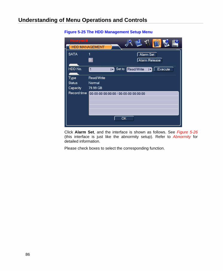
Understanding of Menu Operations and Controls
86
Figure 5-25 The HDD Management Setup Menu
Click Alarm Set, and the interface is shown as follows. See Figure 5-26 (this interface is just like the abnormity setup). Refer to Abnormity for detailed information.
Please check boxes to select the corresponding function.

Honeywell
87
Figure 5-26 The Abnormity Setup Menu
Abnormity
Abnormity interface is shown in Figure 5-27.
• Event type: There are several options for you such as disk error, no disk and etc.
• Alarm output: alarm activation output port (multiple choices). The 3-ch is controllable 12V output.
• Delay: you can set corresponding delaying time. The value ranges from 10s-300s. The system automatically delays specified seconds in turning off the alarm output after the system event is stopped.
• Show message: the system will send message to local screen to alert you when alarm occurs.
• Send email: the system can send out an email to alert you when the alarm occurs.
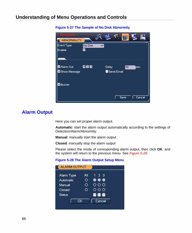
Understanding of Menu Operations and Controls
88
Figure 5-27 The Sample of No Disk Abnormity
Alarm Output
Here you can set proper alarm output.
Automatic: start the alarm output automatically according to the settings of Detection/Alarm/Abnormity.
Manual: manually start the alarm output
Closed: manually stop the alarm output
Please select the mode of corresponding alarm output, then click OK, and the system will return to the previous menu. See Figure 5-28.
Figure 5-28 The Alarm Output Setup Menu
Honeywell
89
Manual Record
Refer to Manual Record.
Account
Here you can implement account management. See Figure 5-29. to see how to:
• Add new user
• Modify user
• Add group
• Modify group
• Modify password.
For account management please note:
• The system account adopts two-level management: group and user. There is no limit to group or user amount.
• For group or user management, there are two levels: admin and user.
• The user name and group name can consist of eight characters of letters, numbers and/or 3 symbols (“_”, “-” “.”). SPACE is not recommended, and SPACE at the start or end of user name will be ignored. One name can be used only once.
• There are four default users: admin/888888/666666 and hidden user “default”. User 888888 and admin have administrator’s right.
• Hidden user “default” is for system interior use only and cannot be deleted. When there is no login user, hidden user “default” automatically login. You can set some rights such as monitor capability for this user so that you can view some channels without login.
• One user should belong to one group. Users’ rights cannot exceed group’s right.
• About reusable function: this function allows multiple users use the same account to login.
After all the setups please click Save, and the system will return to the previous menu.
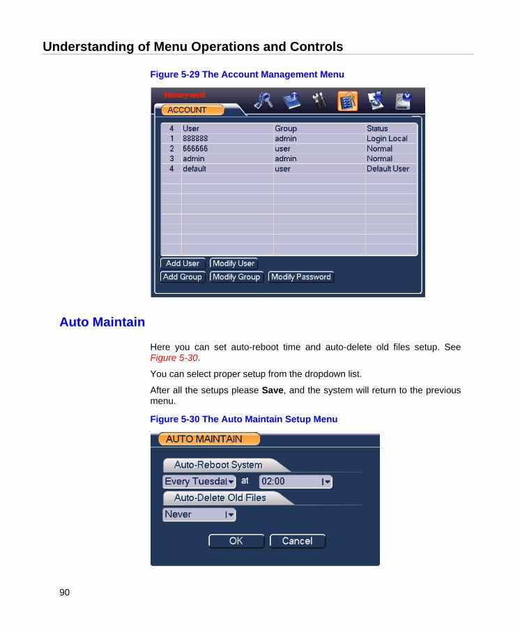
Understanding of Menu Operations and Controls
90
Figure 5-29 The Account Management Menu
Auto Maintain
Here you can set auto-reboot time and auto-delete old files setup. See Figure 5-30.
You can select proper setup from the dropdown list.
After all the setups please Save, and the system will return to the previous menu.
Figure 5-30 The Auto Maintain Setup Menu
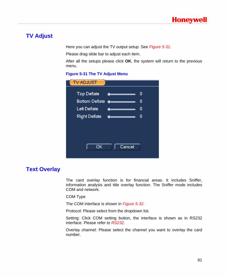
Honeywell
91
TV Adjust
Here you can adjust the TV output setup. See Figure 5-31.
Please drag slide bar to adjust each item.
After all the setups please click OK, the system will return to the previous menu.
Figure 5-31 The TV Adjust Menu
Text Overlay
The card overlay function is for financial areas. It includes Sniffer, information analysis and title overlay function. The Sniffer mode includes COM and network.
COM Type
The COM interface is shown in Figure 5-32.
Protocol: Please select from the dropdown list.
Setting: Click COM setting button, the interface is shown as in RS232 interface. Please refer to RS232.
Overlay channel: Please select the channel you want to overlay the card number.
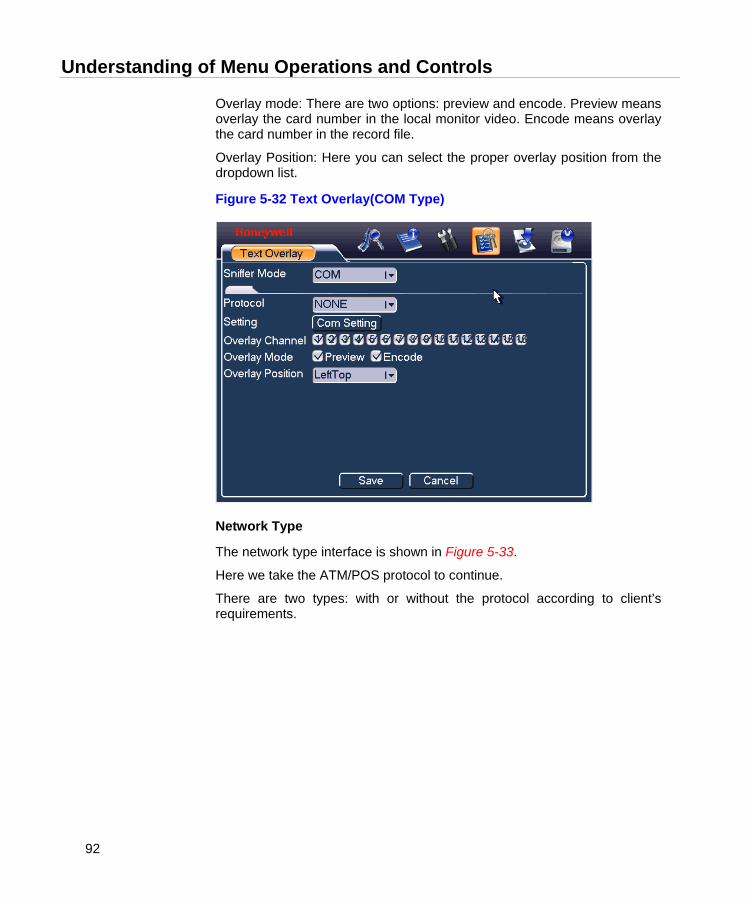
Understanding of Menu Operations and Controls
92
Overlay mode: There are two options: preview and encode. Preview means overlay the card number in the local monitor video. Encode means overlay the card number in the record file.
Overlay Position: Here you can select the proper overlay position from the dropdown list.
Figure 5-32 Text Overlay(COM Type)
Network Type
The network type interface is shown in Figure 5-33.
Here we take the ATM/POS protocol to continue.
There are two types: with or without the protocol according to client’s requirements.
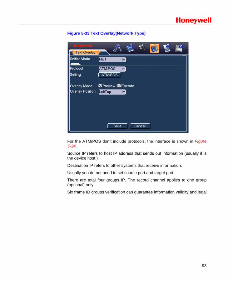
Honeywell
93
Figure 5-33 Text Overlay(Network Type)
For the ATM/POS don’t include protocols, the interface is shown in Figure 5-34.
Source IP refers to host IP address that sends out information (usually it is the device host.)
Destination IP refers to other systems that receive information.
Usually you do not need to set source port and target port.
There are total four groups IP. The record channel applies to one group (optional) only.
Six frame ID groups verification can guarantee information validity and legal.
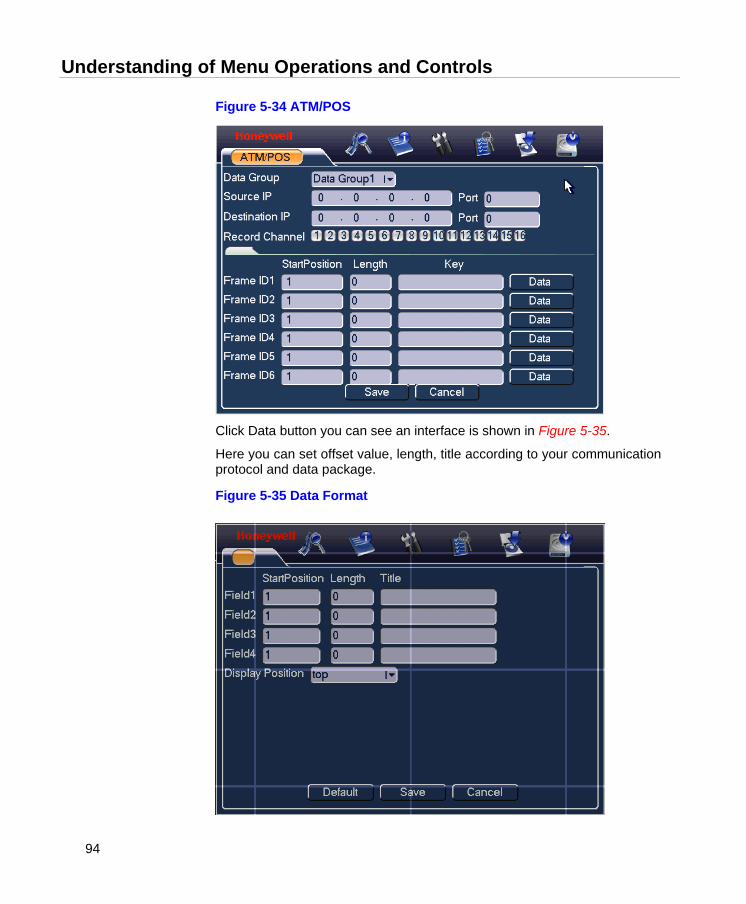
Understanding of Menu Operations and Controls
94
Figure 5-34 ATM/POS
Click Data button you can see an interface is shown in Figure 5-35.
Here you can set offset value, length, title according to your communication protocol and data package.
Figure 5-35 Data Format
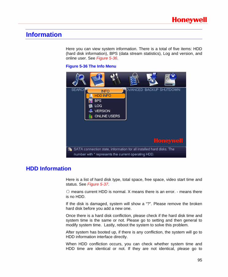
Honeywell
95
Information
Here you can view system information. There is a total of five items: HDD (hard disk information), BPS (data stream statistics), Log and version, and online user. See Figure 5-36.
Figure 5-36 The Info Menu
HDD Information
Here is a list of hard disk type, total space, free space, video start time and status. See Figure 5-37.
○ means current HDD is normal. X means there is an error. - means there is no HDD.
If the disk is damaged, system will show a “?”. Please remove the broken hard disk before you add a new one.
Once there is a hard disk confliction, please check if the hard disk time and system time is the same or not. Please go to setting and then general to modify system time. Lastly, reboot the system to solve this problem.
After system has booted up, if there is any confliction, the system will go to HDD information interface directly.
When HDD confliction occurs, you can check whether system time and HDD time are identical or not. If they are not identical, please go to
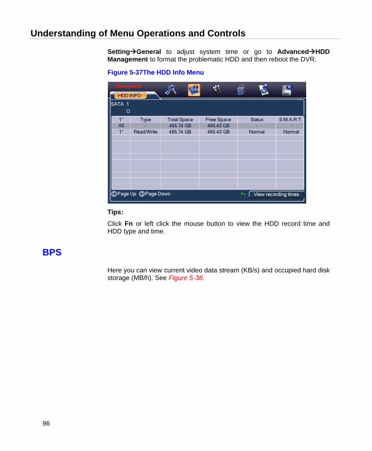
Understanding of Menu Operations and Controls
96
SettingGeneral to adjust system time or go to AdvancedHDD Management to format the problematic HDD and then reboot the DVR.
Figure 5-37The HDD Info Menu
Tips:
Click Fn or left click the mouse button to view the HDD record time and HDD type and time.
BPS
Here you can view current video data stream (KB/s) and occupied hard disk storage (MB/h). See Figure 5-38.

Honeywell
97
Figure 5-38 The BPS Display Menu
Log
Here you can view the system log file. The system lists the following information. See Figure 5-39.
Log types include system operation, configuration operation, data management, alarm event, record operation, log clear and etc.
Select the start time and end time, and then click Search. You can view the log files. Click Page Up or Page Down to view if there are more than ten files.
If a USB storage device is connected to the DVR, you can click Backup to save the displayed logs as a text file FileLog.txt in the USB device.
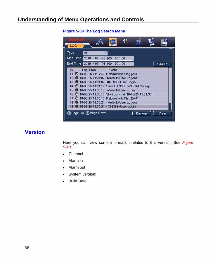
Understanding of Menu Operations and Controls
98
Figure 5-39 The Log Search Menu
Version
Here you can view some information related to this version. See Figure 5-40.
• Channel
• Alarm in
• Alarm out
• System version:
• Build Date
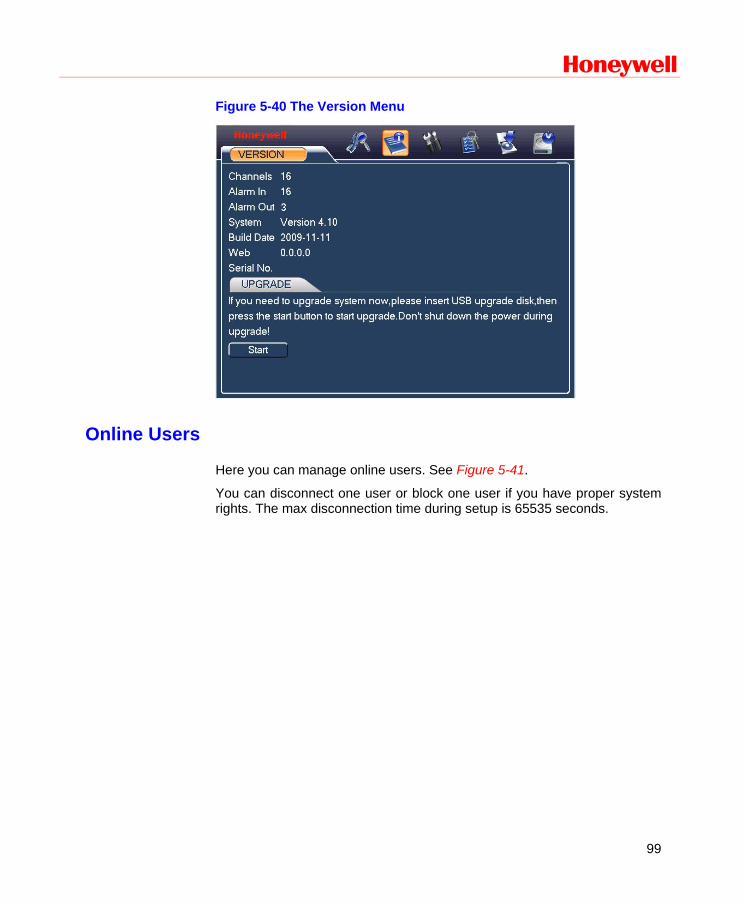
Honeywell
99
Figure 5-40 The Version Menu
Online Users
Here you can manage online users. See Figure 5-41.
You can disconnect one user or block one user if you have proper system rights. The max disconnection time during setup is 65535 seconds.
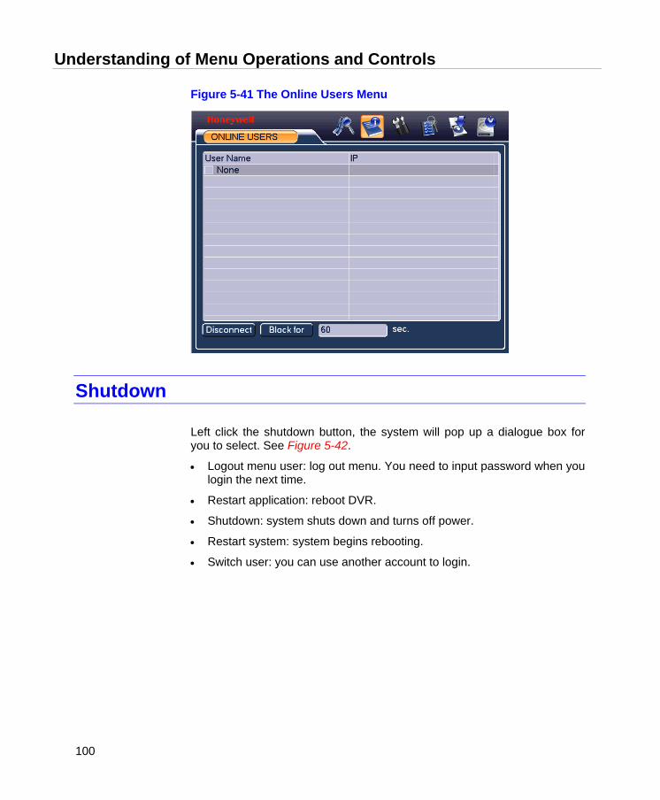
Understanding of Menu Operations and Controls
100
Figure 5-41 The Online Users Menu
Shutdown
Left click the shutdown button, the system will pop up a dialogue box for you to select. See Figure 5-42.
• Logout menu user: log out menu. You need to input password when you login the next time.
• Restart application: reboot DVR.
• Shutdown: system shuts down and turns off power.
• Restart system: system begins rebooting.
• Switch user: you can use another account to login.
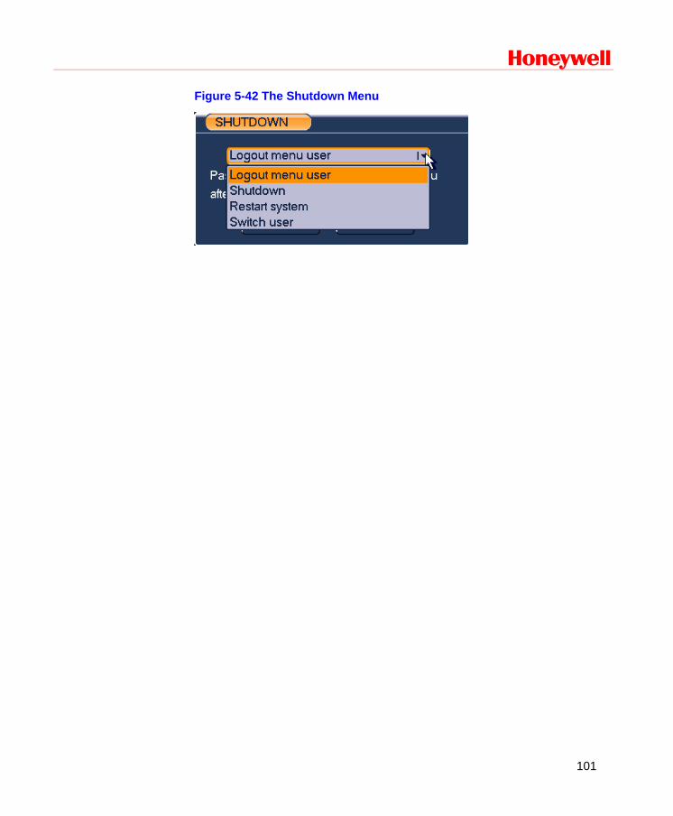
Honeywell
101
Figure 5-42 The Shutdown Menu
Web Client Operation
102
6 Web Client Operation
Note • All the operations here are based on HD-DVR-1016.
• There might be slight differences in the interface due to the updated series.
Network Connection
Before the web client operation, please check the following items:
• Network connection is right
• DVR and PC network setup is right. Please refer to network setup (main menusettingnetwork)
• Use order ping ***.***.***.***(* DVR IP address) to verify that there is a good connection. Usually, the return TTL value should be less than 255.
• Open the IE and then input DVR IP address.
• System can automatically download latest web controls and the new version can overwrite the previous one.
• If you want to un-install the web control, please run uninstall webrec2.0.bat. Or you can go to C:\Program Files\webrec to remove single folder. Please note, before you un-install, please close all web pages, otherwise the un-installation might result in error.
Login
Open IE and input DVR address in the address column. For example, if your DVR IP is 10.10.3.16, then please input http:// 10.10.3.16 in IE address column. See Figure 6-1
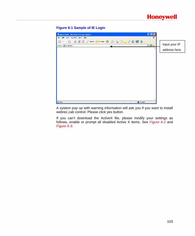
Honeywell
103
Figure 6-1 Sample of IE Login
A system pop up with warning information will ask you if you want to install webrec.cab control. Please click yes button.
If you can’t download the ActiveX file, please modify your settings as follows, enable or prompt all disabled Active X items. See Figure 6-2 and Figure 6-3.
Input your IP
address here.
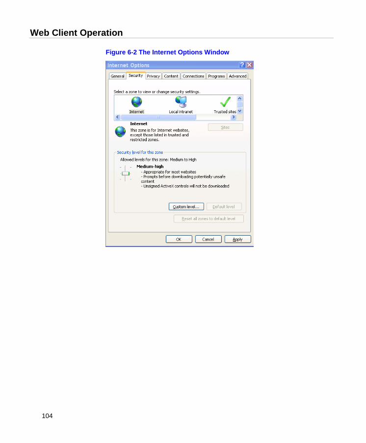
Web Client Operation
104
Figure 6-2 The Internet Options Window
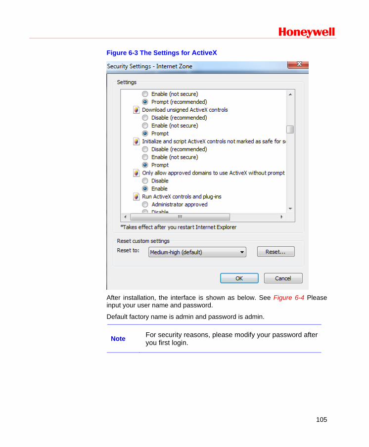
Honeywell
105
Figure 6-3 The Settings for ActiveX
After installation, the interface is shown as below. See Figure 6-4 Please input your user name and password.
Default factory name is admin and password is admin.
Note For security reasons, please modify your password after you first login.
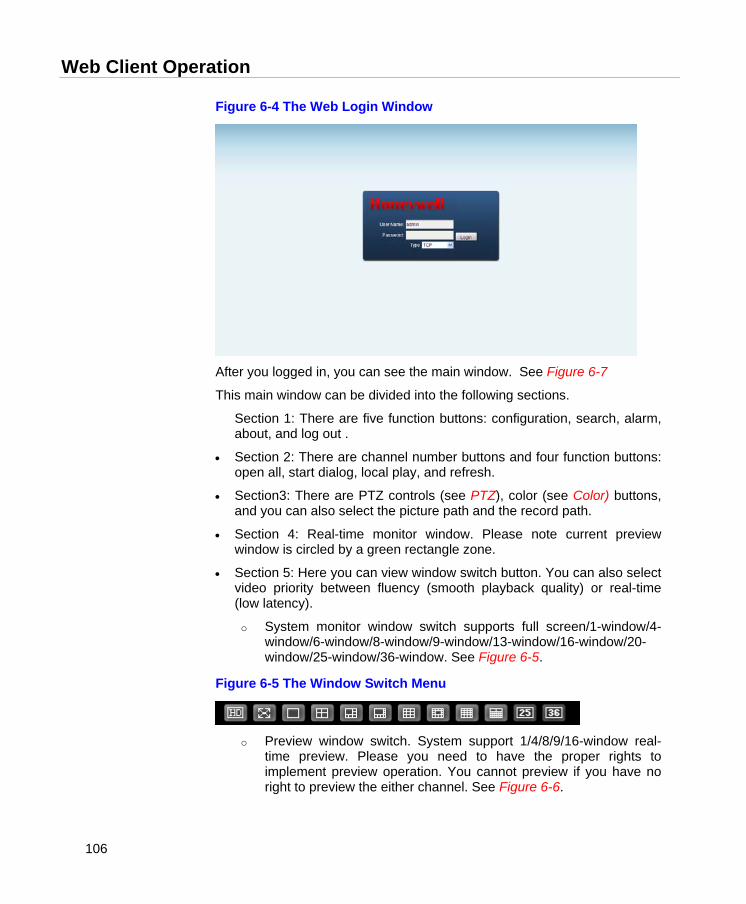
Web Client Operation
106
Figure 6-4 The Web Login Window
After you logged in, you can see the main window. See Figure 6-7
This main window can be divided into the following sections.
Section 1: There are five function buttons: configuration, search, alarm, about, and log out .
• Section 2: There are channel number buttons and four function buttons: open all, start dialog, local play, and refresh.
• Section3: There are PTZ controls (see PTZ), color (see Color) buttons, and you can also select the picture path and the record path.
• Section 4: Real-time monitor window. Please note current preview window is circled by a green rectangle zone.
• Section 5: Here you can view window switch button. You can also select video priority between fluency (smooth playback quality) or real-time (low latency).
o System monitor window switch supports full screen/1-window/4-window/6-window/8-window/9-window/13-window/16-window/20-window/25-window/36-window. See Figure 6-5.
Figure 6-5 The Window Switch Menu
o Preview window switch. System support 1/4/8/9/16-window real-
time preview. Please you need to have the proper rights to implement preview operation. You cannot preview if you have no right to preview the either channel. See Figure 6-6.
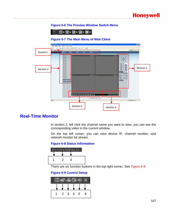
Honeywell
107
Figure 6-6 The Preview Window Switch Menu
Figure 6-7 The Main Menu of Web Client
Real-Time Monitor
In section 2, left click the channel name you want to view, you can see the corresponding video in the current window.
On the top left corner, you can view device IP, channel number, and network monitor bit stream.
Figure 6-8 Status Information
There are six function buttons in the top right corner. See Figure 6-9.
Figure 6-9 Control Setup
1 2 3 4 5 6
1 2 3
Section1
Section 2 Section 3
Section 5 Section 4
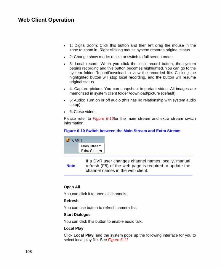
Web Client Operation
108
• 1: Digital zoom: Click this button and then left drag the mouse in the zone to zoom in. Right clicking mouse system restores original status.
• 2: Change show mode: resize or switch to full screen mode.
• 3: Local record. When you click the local record button, the system begins recording and this button becomes highlighted. You can go to the system folder RecordDownload to view the recorded file. Clicking the highlighted button will stop local recording, and the button will resume original status.
• 4: Capture picture. You can snapshoot important video. All images are memorized in system client folder \download\picture (default).
• 5: Audio: Turn on or off audio (this has no relationship with system audio setup).
• 6: Close video.
Please refer to Figure 6-10for the main stream and extra stream switch information.
Figure 6-10 Switch between the Main Stream and Extra Stream
Note If a DVR user changes channel names locally, manual refresh (F5) of the web page is required to update the channel names in the web client.
Open All
You can click it to open all channels.
Refresh
You can use button to refresh camera list.
Start Dialogue You can click this button to enable audio talk.
Local Play
Click Local Play, and the system pops up the following interface for you to select local play file. See Figure 6-11
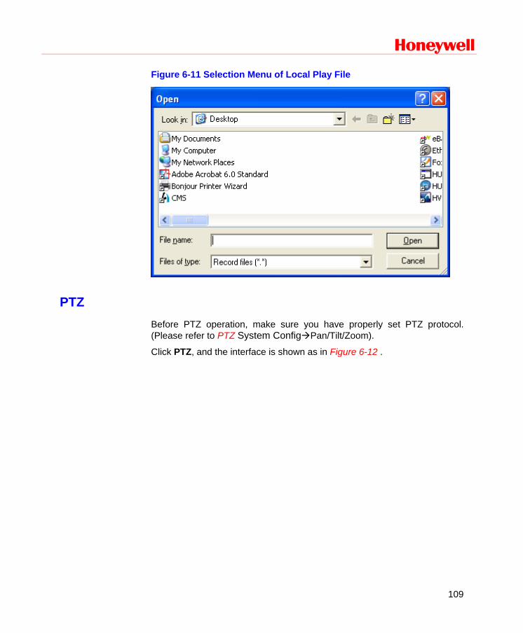
Honeywell
109
Figure 6-11 Selection Menu of Local Play File
PTZ Before PTZ operation, make sure you have properly set PTZ protocol. (Please refer to PTZ System ConfigPan/Tilt/Zoom).
Click PTZ, and the interface is shown as in Figure 6-12 .
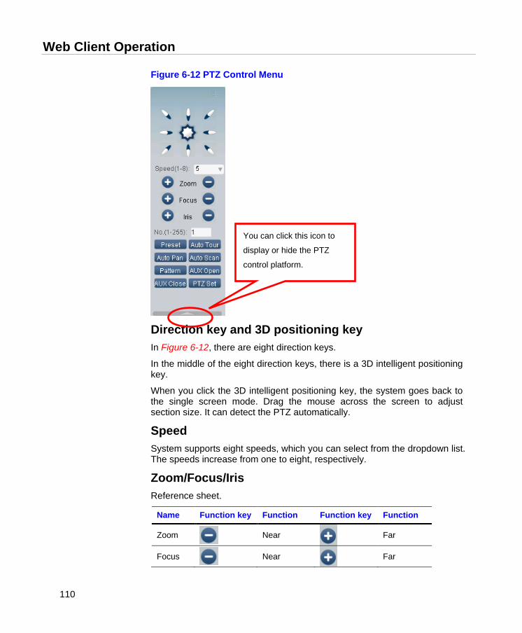
Web Client Operation
110
Figure 6-12 PTZ Control Menu
Direction key and 3D positioning key In Figure 6-12, there are eight direction keys.
In the middle of the eight direction keys, there is a 3D intelligent positioning key.
When you click the 3D intelligent positioning key, the system goes back to the single screen mode. Drag the mouse across the screen to adjust section size. It can detect the PTZ automatically.
Speed System supports eight speeds, which you can select from the dropdown list. The speeds increase from one to eight, respectively.
Zoom/Focus/Iris Reference sheet.
Name Function key Function Function key Function
Zoom
Near
Far
Focus
Near
Far
You can click this icon to
display or hide the PTZ
control platform.
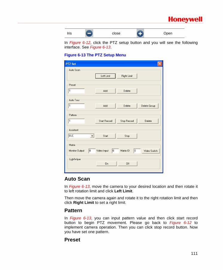
Honeywell
111
Iris
close
Open
In Figure 6-12, click the PTZ setup button and you will see the following interface. See Figure 6-13.
Figure 6-13 The PTZ Setup Menu
Auto Scan In Figure 6-13, move the camera to your desired location and then rotate it to left rotation limit and click Left Limit.
Then move the camera again and rotate it to the right rotation limit and then click Right Limit to set a right limit.
Pattern In Figure 6-13, you can input pattern value and then click start record button to begin PTZ movement. Please go back to Figure 6-12 to implement camera operation. Then you can click stop record button. Now you have set one pattern.
Preset

Web Client Operation
112
In Figure 6-13, move the camera to your desired location and then input preset value. Click the add button, and you will have set one preset.
Auto tour In Figure 6-13, input the auto tour value and preset value. Click the add button, and you will have added one preset in the tour.
Repeat the above procedures to add more presets in one tour.
Assistant You can select the assistant item from the dropdown list. See Figure 6-14.
Figure 6-14 The Assistant Setup Menu
Color
Click “Color” in section 3, and the interface is shown as Figure 6-15.
Here you can select one channel and then adjust its brightness, contrast, hue and saturation. (The current channel border becomes green.)
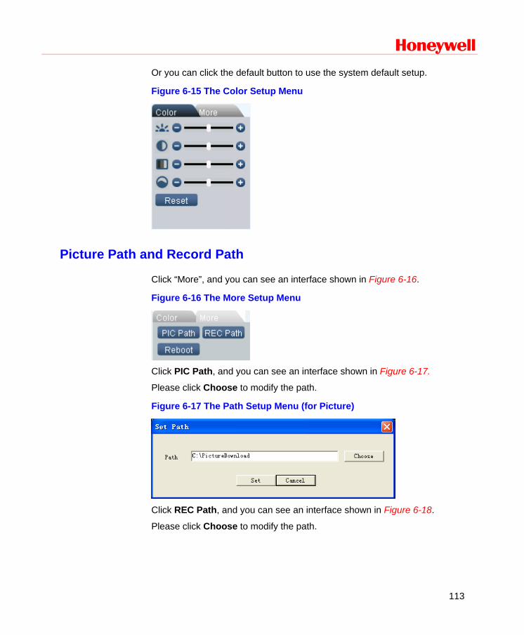
Honeywell
113
Or you can click the default button to use the system default setup.
Figure 6-15 The Color Setup Menu
Picture Path and Record Path
Click “More”, and you can see an interface shown in Figure 6-16.
Figure 6-16 The More Setup Menu
Click PIC Path, and you can see an interface shown in Figure 6-17.
Please click Choose to modify the path.
Figure 6-17 The Path Setup Menu (for Picture)
Click REC Path, and you can see an interface shown in Figure 6-18.
Please click Choose to modify the path.

Web Client Operation
114
Figure 6-18 The Path Setup Menu (for Record)
Click Reboot, and the system pops up the following dialog box. See Figure 6-19. Please click OK to reboot.
Figure 6-19 The Reboot Dialog
Note
If there’s an administrator (e.g. 888888) logged in DVR local menu, or web user doesn’t have device reboot privilege, DVR won’t be rebooted and a warning message box will be prompted.
Configuration
System Information
Version Information Here you can view device hardware feature and software version information. See Figure 6-20.
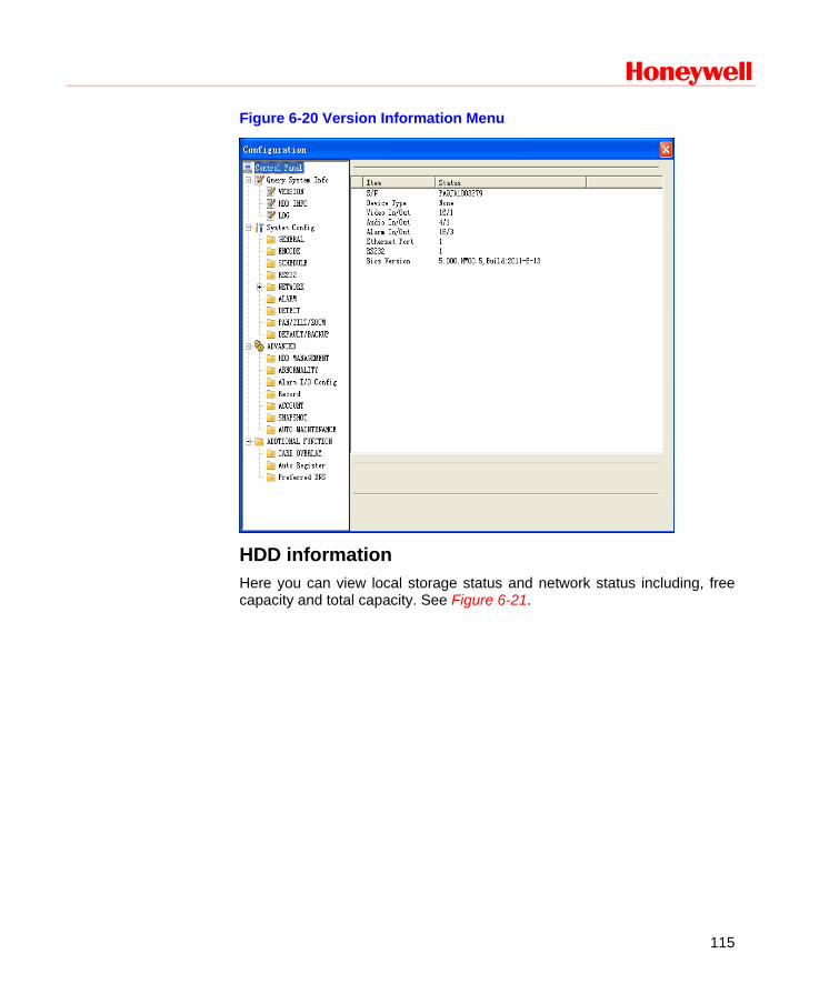
Honeywell
115
Figure 6-20 Version Information Menu
HDD information Here you can view local storage status and network status including, free capacity and total capacity. See Figure 6-21.
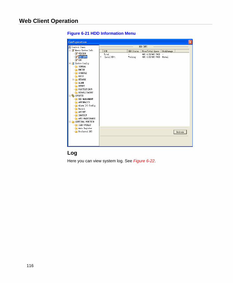
Web Client Operation
116
Figure 6-21 HDD Information Menu
Log Here you can view system log. See Figure 6-22.
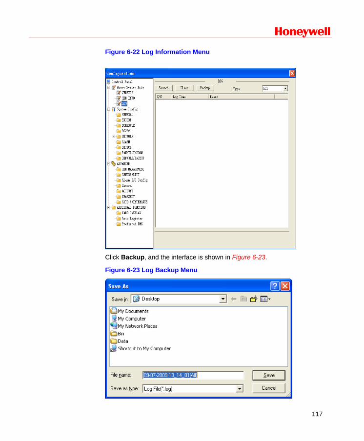
Honeywell
117
Figure 6-22 Log Information Menu
Click Backup, and the interface is shown in Figure 6-23.
Figure 6-23 Log Backup Menu
Web Client Operation
118
Please refer to the following sheet for log parameter information.
Parameter Function
Type Log types include: system operation, configuration operation, data management, alarm event, record operation, user management, log clear and file operation.
Search You can select log type from the drop-down list and then click Search to view the list.
Clear You can click this button to delete all displayed log files. Please note system does not support clear by type.
Backup You can click this button to backup log files to current PC.
System Configuration
Please click Save to save your current setup.
General Setup Here you can set system time, record length, video format, etc. See Figure 6-24.
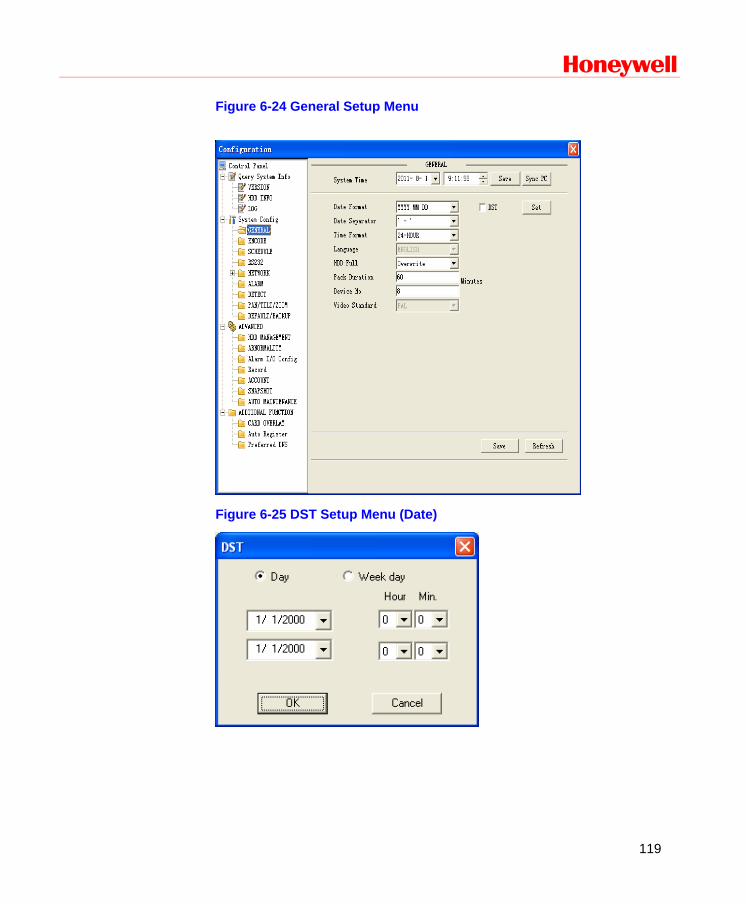
Honeywell
119
Figure 6-24 General Setup Menu
Figure 6-25 DST Setup Menu (Date)
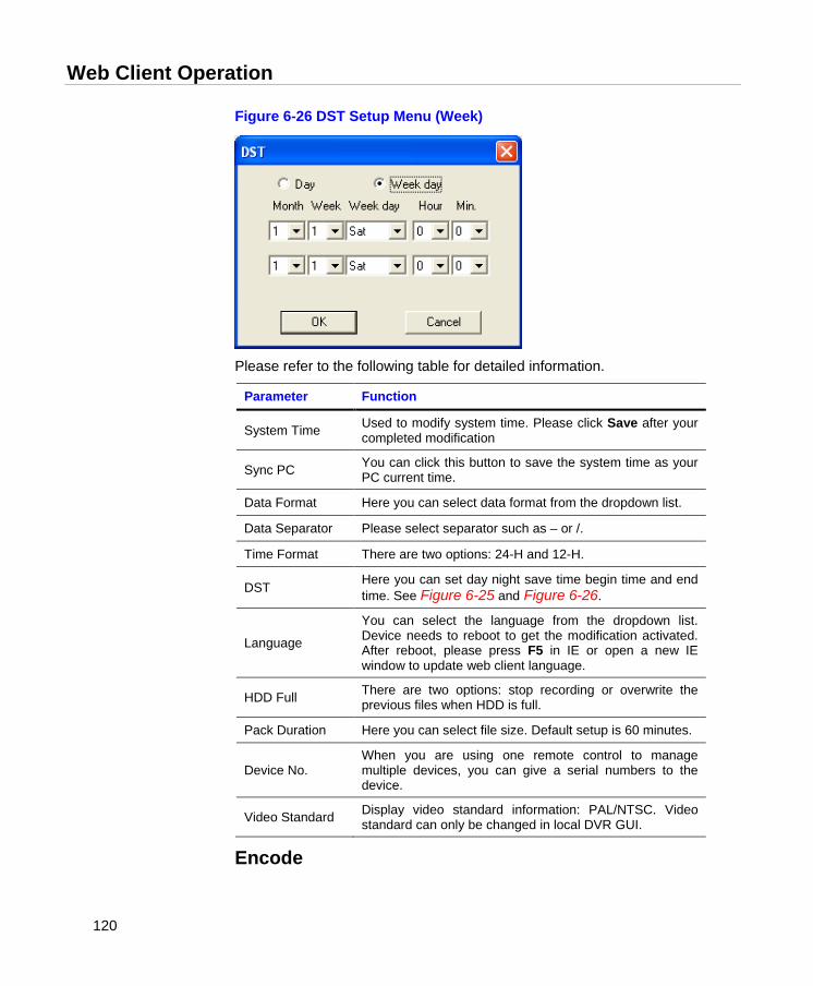
Web Client Operation
120
Figure 6-26 DST Setup Menu (Week)
Please refer to the following table for detailed information.
Parameter Function
System Time Used to modify system time. Please click Save after your completed modification
Sync PC You can click this button to save the system time as your PC current time.
Data Format Here you can select data format from the dropdown list.
Data Separator Please select separator such as – or /.
Time Format There are two options: 24-H and 12-H.
DST Here you can set day night save time begin time and end time. See Figure 6-25 and Figure 6-26.
Language
You can select the language from the dropdown list. Device needs to reboot to get the modification activated. After reboot, please press F5 in IE or open a new IE window to update web client language.
HDD Full There are two options: stop recording or overwrite the previous files when HDD is full.
Pack Duration Here you can select file size. Default setup is 60 minutes.
Device No. When you are using one remote control to manage multiple devices, you can give a serial numbers to the device.
Video Standard Display video standard information: PAL/NTSC. Video standard can only be changed in local DVR GUI.
Encode
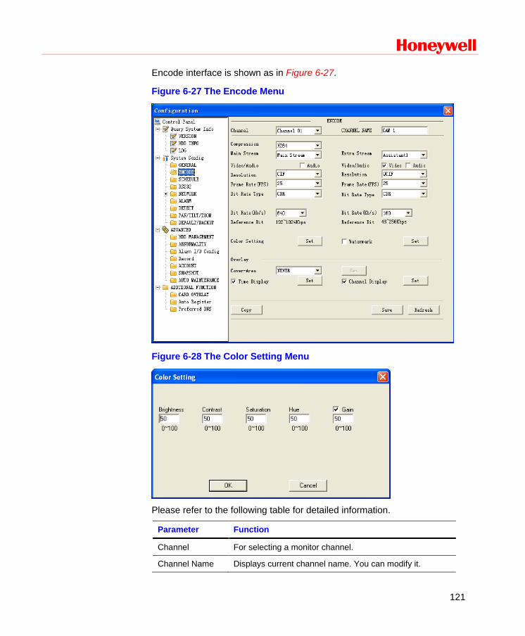
Honeywell
121
Encode interface is shown as in Figure 6-27.
Figure 6-27 The Encode Menu
Figure 6-28 The Color Setting Menu
Please refer to the following table for detailed information.
Parameter Function
Channel For selecting a monitor channel.
Channel Name Displays current channel name. You can modify it.
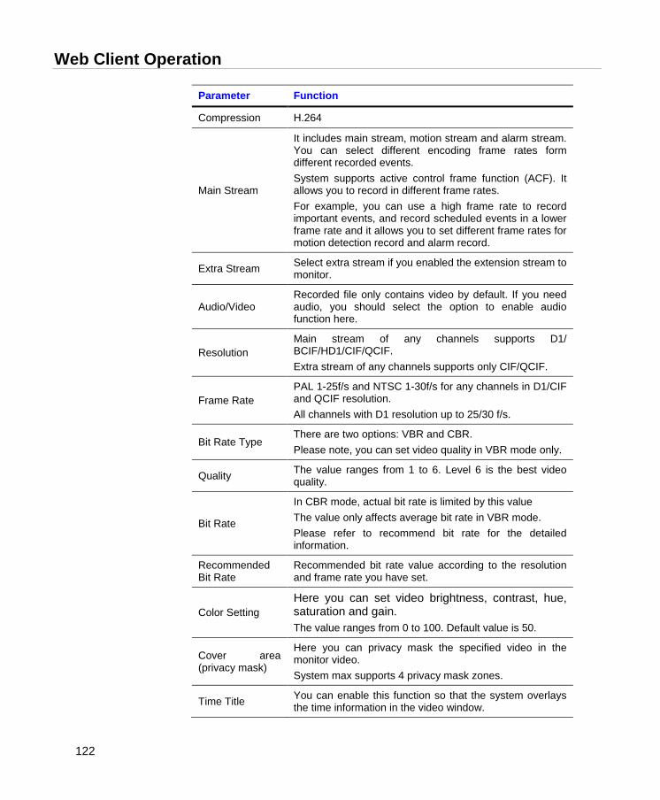
Web Client Operation
122
Parameter Function
Compression H.264
Main Stream
It includes main stream, motion stream and alarm stream. You can select different encoding frame rates form different recorded events. System supports active control frame function (ACF). It allows you to record in different frame rates. For example, you can use a high frame rate to record important events, and record scheduled events in a lower frame rate and it allows you to set different frame rates for motion detection record and alarm record.
Extra Stream Select extra stream if you enabled the extension stream to monitor.
Audio/Video Recorded file only contains video by default. If you need audio, you should select the option to enable audio function here.
Resolution Main stream of any channels supports D1/ BCIF/HD1/CIF/QCIF. Extra stream of any channels supports only CIF/QCIF.
Frame Rate PAL 1-25f/s and NTSC 1-30f/s for any channels in D1/CIF and QCIF resolution. All channels with D1 resolution up to 25/30 f/s.
Bit Rate Type There are two options: VBR and CBR. Please note, you can set video quality in VBR mode only.
Quality The value ranges from 1 to 6. Level 6 is the best video quality.
Bit Rate
In CBR mode, actual bit rate is limited by this value The value only affects average bit rate in VBR mode. Please refer to recommend bit rate for the detailed information.
Recommended Bit Rate
Recommended bit rate value according to the resolution and frame rate you have set.
Color Setting Here you can set video brightness, contrast, hue, saturation and gain. The value ranges from 0 to 100. Default value is 50.
Cover area (privacy mask)
Here you can privacy mask the specified video in the monitor video. System max supports 4 privacy mask zones.
Time Title You can enable this function so that the system overlays the time information in the video window.
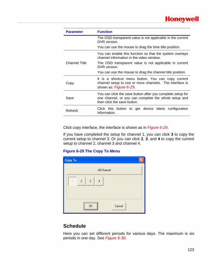
Honeywell
123
Parameter Function The OSD transparent value is not applicable in the current DVR version. You can use the mouse to drag the time tilte position.
Channel Title
You can enable this function so that the system overlays channel information in the video window. The OSD transparent value is not applicable in current DVR version. You can use the mouse to drag the channel title position.
Copy It is a shortcut menu button. You can copy current channel setup to one or more channels. The interface is shown as: Figure 6-29.
Save You can click the save button after you complete setup for one channel, or you can complete the whole setup and then click the save button.
Refresh Click this button to get device latest configuration information.
Click copy interface, the interface is shown as in Figure 6-29.
If you have completed the setup for channel 1, you can click 3 to copy the current setup to channel 3. Or you can click 2, 3, and 4 to copy the current setup to channel 2, channel 3 and channel 4.
Figure 6-29 The Copy To Menu
Schedule Here you can set different periods for various days. The maximum is six periods in one day. See Figure 6-30.
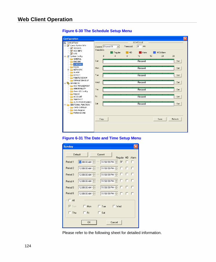
Web Client Operation
124
Figure 6-30 The Schedule Setup Menu
Figure 6-31 The Date and Time Setup Menu
Please refer to the following sheet for detailed information.
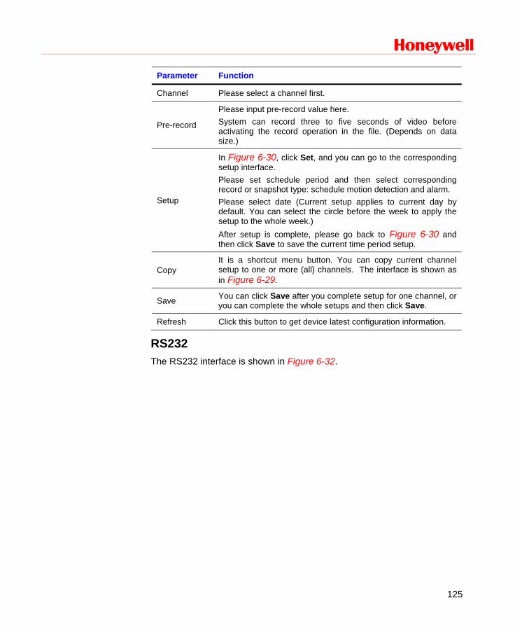
Honeywell
125
Parameter Function
Channel Please select a channel first.
Pre-record
Please input pre-record value here. System can record three to five seconds of video before activating the record operation in the file. (Depends on data size.)
Setup
In Figure 6-30, click Set, and you can go to the corresponding setup interface. Please set schedule period and then select corresponding record or snapshot type: schedule motion detection and alarm. Please select date (Current setup applies to current day by default. You can select the circle before the week to apply the setup to the whole week.) After setup is complete, please go back to Figure 6-30 and then click Save to save the current time period setup.
Copy It is a shortcut menu button. You can copy current channel setup to one or more (all) channels. The interface is shown as in Figure 6-29.
Save You can click Save after you complete setup for one channel, or you can complete the whole setups and then click Save.
Refresh Click this button to get device latest configuration information.
RS232 The RS232 interface is shown in Figure 6-32.
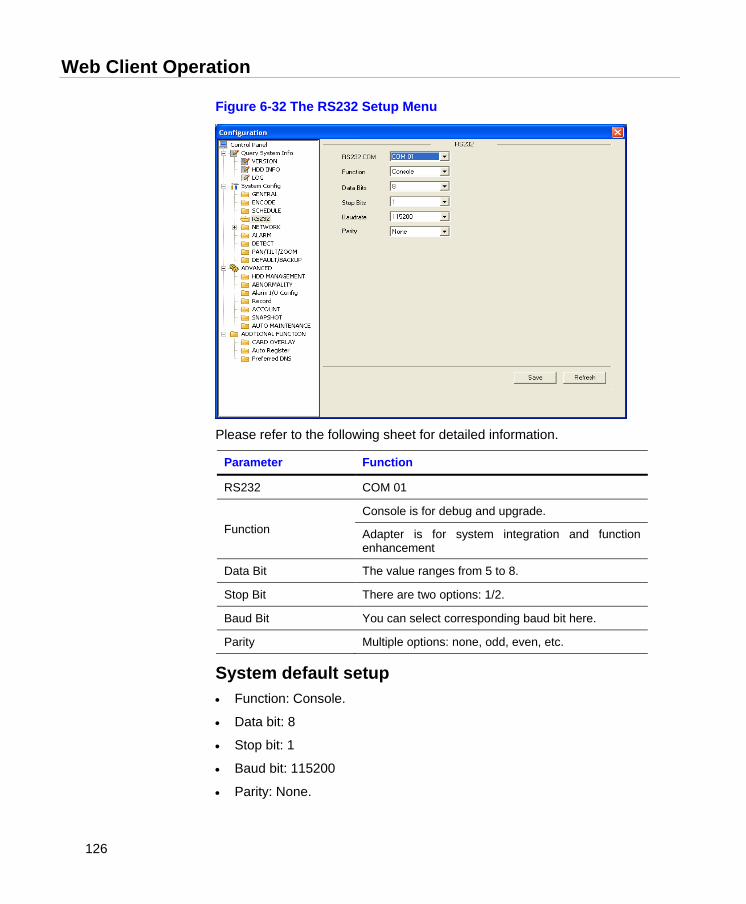
Web Client Operation
126
Figure 6-32 The RS232 Setup Menu
Please refer to the following sheet for detailed information.
Parameter Function
RS232 COM 01
Function Console is for debug and upgrade.
Adapter is for system integration and function enhancement
Data Bit The value ranges from 5 to 8.
Stop Bit There are two options: 1/2.
Baud Bit You can select corresponding baud bit here.
Parity Multiple options: none, odd, even, etc.
System default setup • Function: Console.
• Data bit: 8
• Stop bit: 1
• Baud bit: 115200
• Parity: None.
Honeywell
127
Network The network interface is shown as in Figure 6-33.
Figure 6-33 The Network Setup Menu
Please refer to the following sheet for detailed information.
Parameter Function
Ethernet Please select the network card first.
DHCP Dynamically get IP address. You can get the device IP from the DHCP server if you enabled this function.
TCP Port Default value is 37777.
HTTP Port Default value is 80.
Max Connection Network user max amount. The value ranges from 0 to 10. 0 means there is no user can access current device.
Remote Host PPPOE
Input the PPPoE user name and password you get from the IPS (internet service provider) and enable PPPoE function. Please save current setup and then reboot the device to get the setup activated.
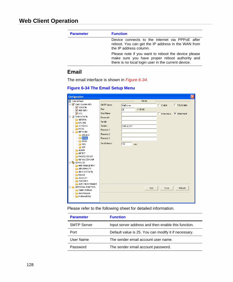
Web Client Operation
128
Parameter Function Device connects to the internet via PPPoE after reboot. You can get the IP address in the WAN from the IP address column. Please note if you want to reboot the device please make sure you have proper reboot authority and there is no local login user in the current device.
Email The email interface is shown in Figure 6-34.
Figure 6-34 The Email Setup Menu
Please refer to the following sheet for detailed information.
Parameter Function
SMTP Server Input server address and then enable this function.
Port Default value is 25. You can modify it if necessary.
User Name The sender email account user name.
Password The sender email account password.
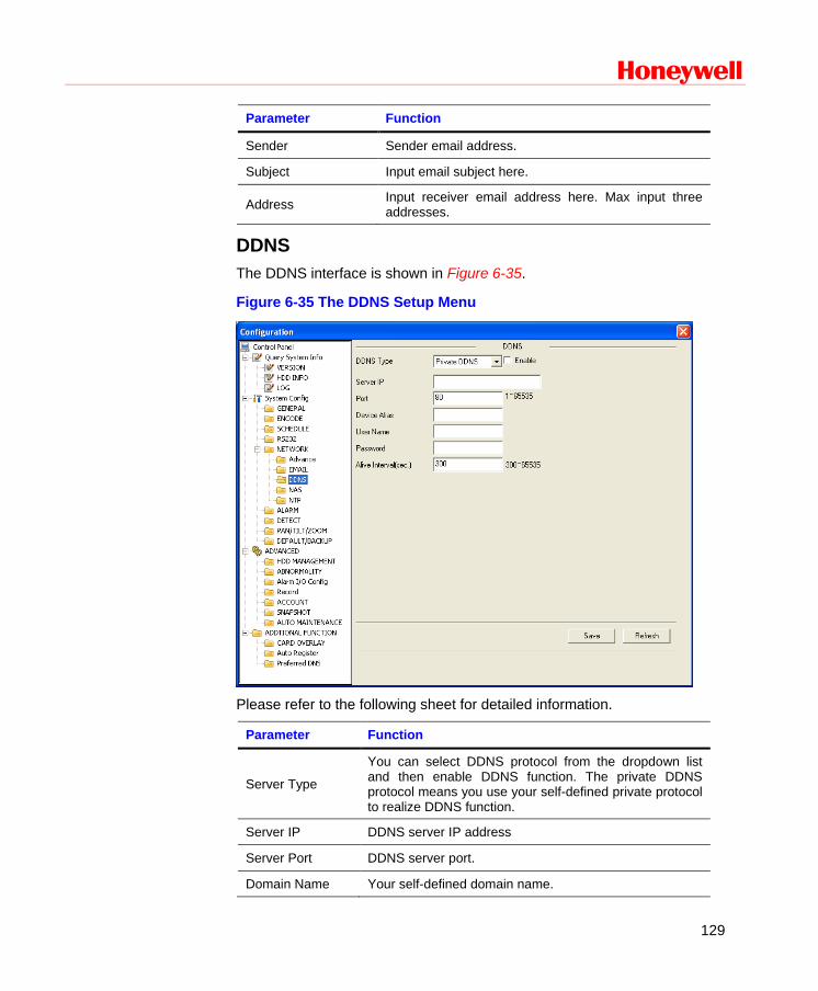
Honeywell
129
Parameter Function
Sender Sender email address.
Subject Input email subject here.
Address Input receiver email address here. Max input three addresses.
DDNS The DDNS interface is shown in Figure 6-35.
Figure 6-35 The DDNS Setup Menu
Please refer to the following sheet for detailed information.
Parameter Function
Server Type
You can select DDNS protocol from the dropdown list and then enable DDNS function. The private DDNS protocol means you use your self-defined private protocol to realize DDNS function.
Server IP DDNS server IP address
Server Port DDNS server port.
Domain Name Your self-defined domain name.
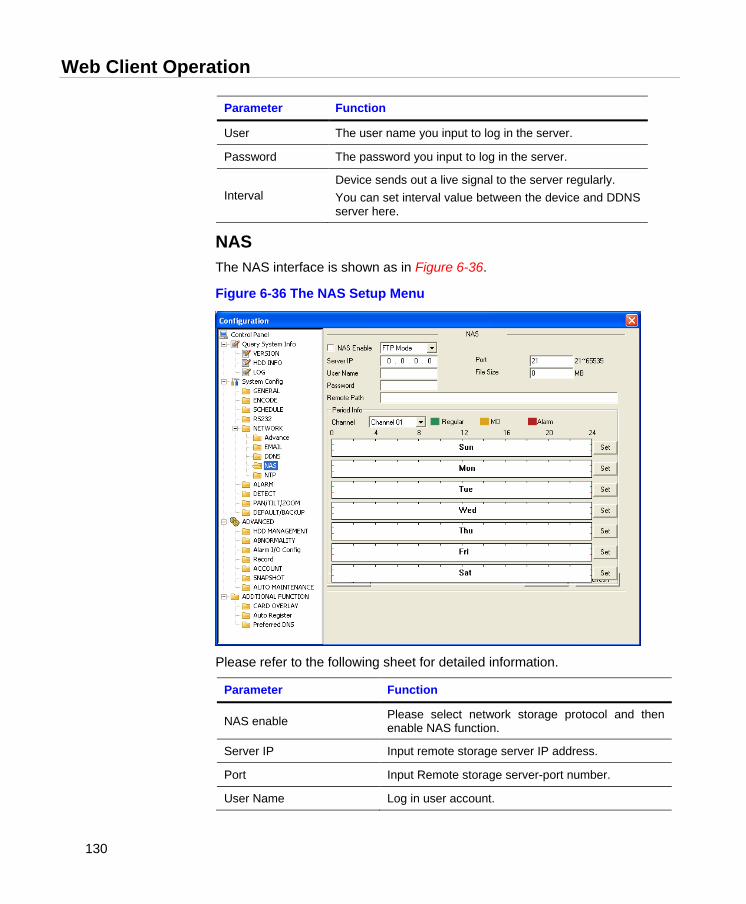
Web Client Operation
130
Parameter Function
User The user name you input to log in the server.
Password The password you input to log in the server.
Interval Device sends out a live signal to the server regularly. You can set interval value between the device and DDNS server here.
NAS The NAS interface is shown as in Figure 6-36.
Figure 6-36 The NAS Setup Menu
Please refer to the following sheet for detailed information.
Parameter Function
NAS enable Please select network storage protocol and then enable NAS function.
Server IP Input remote storage server IP address.
Port Input Remote storage server-port number.
User Name Log in user account.
Honeywell
131
Parameter Function
File length
The file length you upload to the FTP. When the setup is larger than the actual file length, the system will upload the whole file. When the setup is smaller than the actual file length, the system only uploads the set length and auto ignores the remaining section. When interval value is 0, the system uploads all corresponding files.
Password The password you need to log in the server.
Remote Path Remote storage file path.
Save You can click Save after you complete setup for one channel, or you can complete the whole setup and then click the save button.
Refresh Click this button to get device latest configuration information.
NTP The NTP interface is shown in Figure 6-37.
Here you can realize network time synchronization. Please enable current function and then input server IP, port number, time zone and update interval.
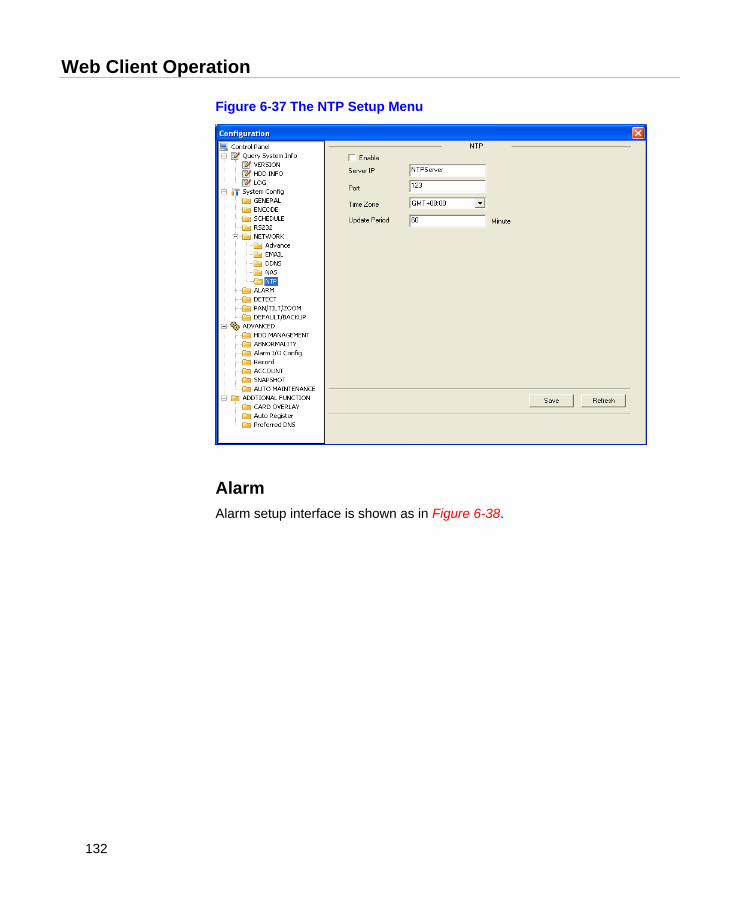
Web Client Operation
132
Figure 6-37 The NTP Setup Menu
Alarm Alarm setup interface is shown as in Figure 6-38.

Honeywell
133
Figure 6-38 The Alarm Setup Menu
Please refer to the following sheet for detailed information.
Parameter Function
Event Type It includes local alarm/network alarm. Local alarm: Device detects alarm from input port. Network: Device detects alarm from network.
Alarm in Select corresponding alarm channel, and check the checkbox beside it to enable system to detect alarm signal
Type There are two options: normal open and normal close. NO becomes activated in low voltage, NC becomes activated in high voltage.
Period
Alarm record function becomes activated in the specified periods. There are six periods in one day. Please check the checkbox to enable corresponding period. Select date. If you do not, the current setup applies to today only. You can select the all week column to apply it to the whole week. Click OK button, system goes back to alarm setup interface, please click save button to exit.
Anti-dither Not effective in current DVR version.
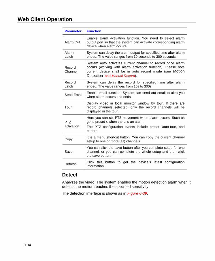
Web Client Operation
134
Parameter Function
Alarm Out Enable alarm activation function. You need to select alarm output port so that the system can activate corresponding alarm device when alarm occurs.
Alarm Latch
System can delay the alarm output for specified time after alarm ended. The value ranges from 10 seconds to 300 seconds.
Record Channel
System auto activates current channel to record once alarm occurs (working with alarm activation function). Please note current device shall be in auto record mode (see Motion Detection and Manual Record).
Record Latch
System can delay the record for specified time after alarm ended. The value ranges from 10s to 300s.
Send Email Enable email function. System can send out email to alert you when alarm occurs and ends.
Tour Display video in local monitor window by tour. If there are record channels selected, only the record channels will be displayed in the tour.
PTZ activation
Here you can set PTZ movement when alarm occurs. Such as go to preset x when there is an alarm. The PTZ configuration events include preset, auto-tour, and pattern.
Copy It is a menu shortcut button. You can copy the current channel setup to one or more (all) channels.
Save You can click the save button after you complete setup for one channel, or you can complete the whole setup and then click the save button.
Refresh Click this button to get the device’s latest configuration information.
Detect Analyzes the video. The system enables the motion detection alarm when it detects the motion reaches the specified sensitivity.
The detection interface is shown as in Figure 6-39.
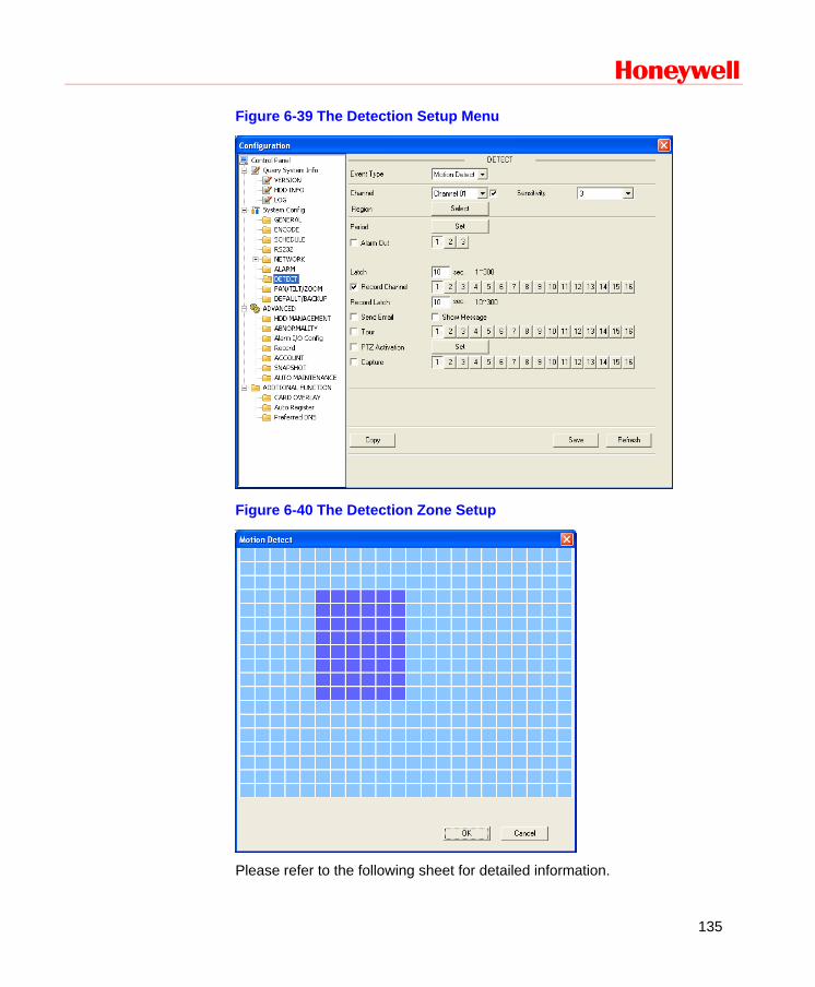
Honeywell
135
Figure 6-39 The Detection Setup Menu
Figure 6-40 The Detection Zone Setup
Please refer to the following sheet for detailed information.
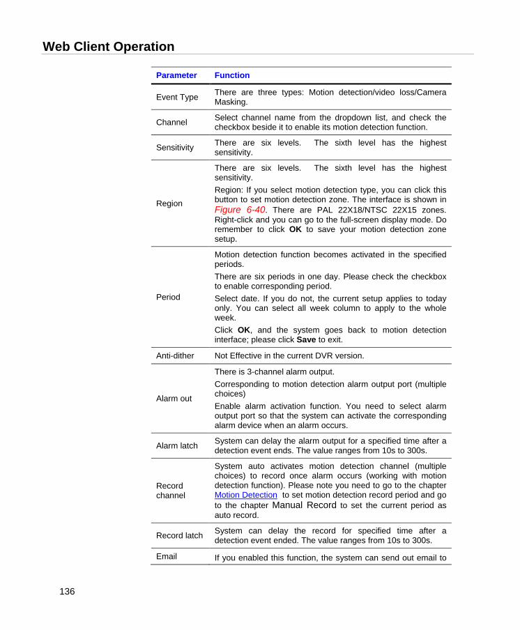
Web Client Operation
136
Parameter Function
Event Type There are three types: Motion detection/video loss/Camera Masking.
Channel Select channel name from the dropdown list, and check the checkbox beside it to enable its motion detection function.
Sensitivity There are six levels. The sixth level has the highest sensitivity.
Region
There are six levels. The sixth level has the highest sensitivity. Region: If you select motion detection type, you can click this button to set motion detection zone. The interface is shown in Figure 6-40. There are PAL 22X18/NTSC 22X15 zones. Right-click and you can go to the full-screen display mode. Do remember to click OK to save your motion detection zone setup.
Period
Motion detection function becomes activated in the specified periods. There are six periods in one day. Please check the checkbox to enable corresponding period. Select date. If you do not, the current setup applies to today only. You can select all week column to apply to the whole week. Click OK, and the system goes back to motion detection interface; please click Save to exit.
Anti-dither Not Effective in the current DVR version.
Alarm out
There is 3-channel alarm output. Corresponding to motion detection alarm output port (multiple choices) Enable alarm activation function. You need to select alarm output port so that the system can activate the corresponding alarm device when an alarm occurs.
Alarm latch System can delay the alarm output for a specified time after a detection event ends. The value ranges from 10s to 300s.
Record channel
System auto activates motion detection channel (multiple choices) to record once alarm occurs (working with motion detection function). Please note you need to go to the chapter Motion Detection to set motion detection record period and go to the chapter Manual Record to set the current period as auto record.
Record latch System can delay the record for specified time after a detection event ended. The value ranges from 10s to 300s.
Email If you enabled this function, the system can send out email to
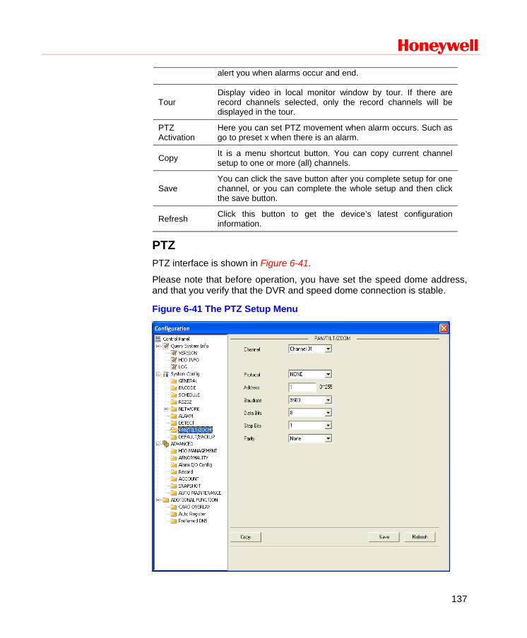
Honeywell
137
alert you when alarms occur and end.
Tour Display video in local monitor window by tour. If there are record channels selected, only the record channels will be displayed in the tour.
PTZ Activation
Here you can set PTZ movement when alarm occurs. Such as go to preset x when there is an alarm.
Copy It is a menu shortcut button. You can copy current channel setup to one or more (all) channels.
Save You can click the save button after you complete setup for one channel, or you can complete the whole setup and then click the save button.
Refresh Click this button to get the device’s latest configuration information.
PTZ PTZ interface is shown in Figure 6-41.
Please note that before operation, you have set the speed dome address, and that you verify that the DVR and speed dome connection is stable.
Figure 6-41 The PTZ Setup Menu
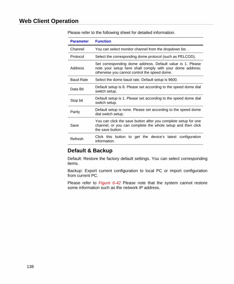
Web Client Operation
138
Please refer to the following sheet for detailed information.
Parameter Function
Channel You can select monitor channel from the dropdown list. .
Protocol Select the corresponding dome protocol (such as PELCOD),
Address Set corresponding dome address. Default value is 1. Please note your setup here shall comply with your dome address; otherwise you cannot control the speed dome.
Baud Rate Select the dome baud rate. Default setup is 9600.
Data Bit Default setup is 8. Please set according to the speed dome dial switch setup.
Stop bit Default setup is 1. Please set according to the speed dome dial switch setup.
Parity Default setup is none. Please set according to the speed dome dial switch setup.
Save You can click the save button after you complete setup for one channel, or you can complete the whole setup and then click the save button.
Refresh Click this button to get the device’s latest configuration information.
Default & Backup Default: Restore the factory default settings. You can select corresponding items.
Backup: Export current configuration to local PC or import configuration from current PC.
Please refer to Figure 6-42 Please note that the system cannot restore some information such as the network IP address.
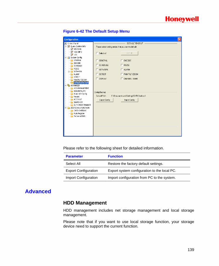
Honeywell
139
Figure 6-42 The Default Setup Menu
Please refer to the following sheet for detailed information.
Parameter Function
Select All Restore the factory default settings.
Export Configuration Export system configuration to the local PC.
Import Configuration Import configuration from PC to the system.
Advanced
HDD Management HDD management includes net storage management and local storage management.
Please note that if you want to use local storage function, your storage device need to support the current function.
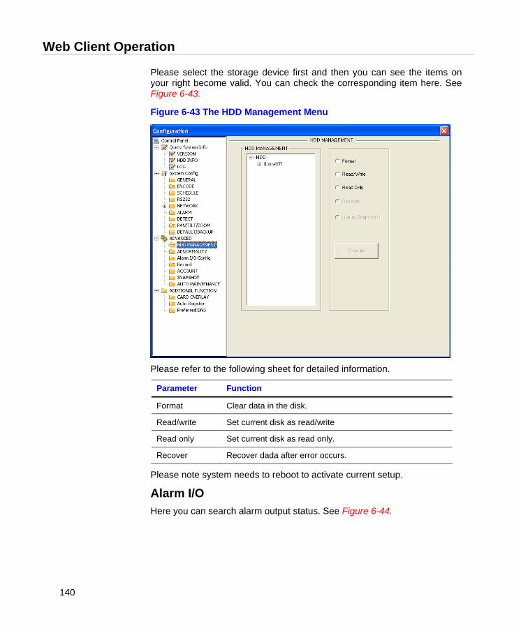
Web Client Operation
140
Please select the storage device first and then you can see the items on your right become valid. You can check the corresponding item here. See Figure 6-43.
Figure 6-43 The HDD Management Menu
Please refer to the following sheet for detailed information.
Parameter Function
Format Clear data in the disk.
Read/write Set current disk as read/write
Read only Set current disk as read only.
Recover Recover dada after error occurs.
Please note system needs to reboot to activate current setup.
Alarm I/O Here you can search alarm output status. See Figure 6-44.
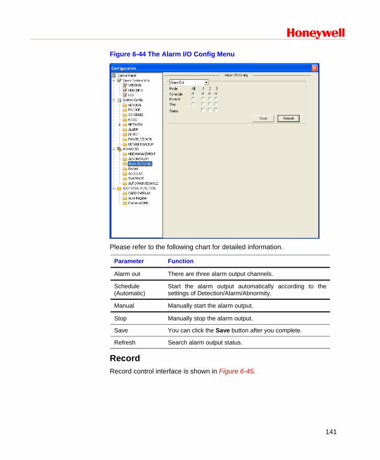
Honeywell
141
Figure 6-44 The Alarm I/O Config Menu
Please refer to the following chart for detailed information.
Parameter Function
Alarm out There are three alarm output channels.
Schedule (Automatic)
Start the alarm output automatically according to the settings of Detection/Alarm/Abnormity.
Manual Manually start the alarm output.
Stop Manually stop the alarm output.
Save You can click the Save button after you complete.
Refresh Search alarm output status.
Record Record control interface is shown in Figure 6-45.

Web Client Operation
142
Figure 6-45 The Record Control Menu
Please refer to the following chart for detailed information.
Parameter Function
Schedule (Auto)
The system enables the auto record function as you set in record schedule setup.
Manual Enable corresponding channel to record no matter what period is applied in the record setup.
Stop Stop current channel record no matter what period is applied in the record setup.
Operation here is the same as the one described in Manual Record. Please refer to this chapter for detailed information.
Account Here you can add, remove users or modify passwords. See Figure 6-46.

Honeywell
143
Figure 6-46 The Account Management Menu
Auto Maintenance Here you can select auto reboot and auto delete old file intervals from the dropdown list. See Figure 6-47.
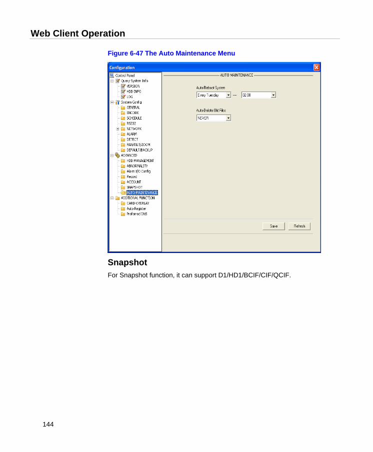
Web Client Operation
144
Figure 6-47 The Auto Maintenance Menu
Snapshot For Snapshot function, it can support D1/HD1/BCIF/CIF/QCIF.
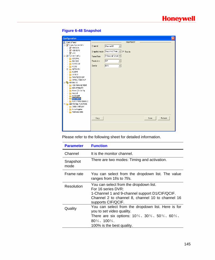
Honeywell
145
Figure 6-48 Snapshot
Please refer to the following sheet for detailed information.
Parameter Function
Channel It is the monitor channel.
Snapshot mode
There are two modes: Timing and activation.
Frame rate You can select from the dropdown list. The value ranges from 1f/s to 7f/s.
Resolution You can select from the dropdown list. For 16 series DVR: 1-Channel 1 and 9-channel support D1/CIF/QCIF. Channel 2 to channel 8, channel 10 to channel 16 supports CIF/QCIF.
Quality You can select from the dropdown list. Here is for you to set video quality. There are six options: 10%、30%、50%、60%、
80%、100%. 100% is the best quality.

Web Client Operation
146
Abnormity The abnormity interface is shown as below.
Figure 6-49 The Abnormity Setup Menu
Please refer to the following chart for detailed information.
Parameter Function
Event Type Possible abnormal errors include: no disk, disk no space, disk error, net error. You need to draw a circle to enable this function.
Alarm Out The corresponding alarm activation output channel when alarm occurs, There are three channels.
Latch
The alarm output can be delayed for the specified time after the alarm stops. Then the system disables alarm and corresponding activation output. The value ranges from 10s to 300s.
Send email If you enable this function, the system can send out an email to notify the specified user.
Show The system can display alarm information in the local DVR

Honeywell
147
message screen.
Additional Function
DNS Here you can set server or local operator DNS address. See Figure 6-50below.
Figure 6-50 DNS
ATM/POS The ATM/POS function is the same with the card overlay function. It is mainly for financial areas to Sniffer, information parse and character overlay. The ATM/POS interface is shown in Figure 6-51.
Source IP refers to host IP address that sends out information (usually it is the device host connected to the DVR.)
Destination IP refers to other systems that receive information.

Web Client Operation
148
There are total four groups IP. The record channel applies to one group (optional) only.
Six frame ID groups verification can guarantee information validity and legal.
The start position, length and data can be set according to your protocol and data packet. There are total four fields.
Figure 6-51 CARD OVERLAY
Auto Register
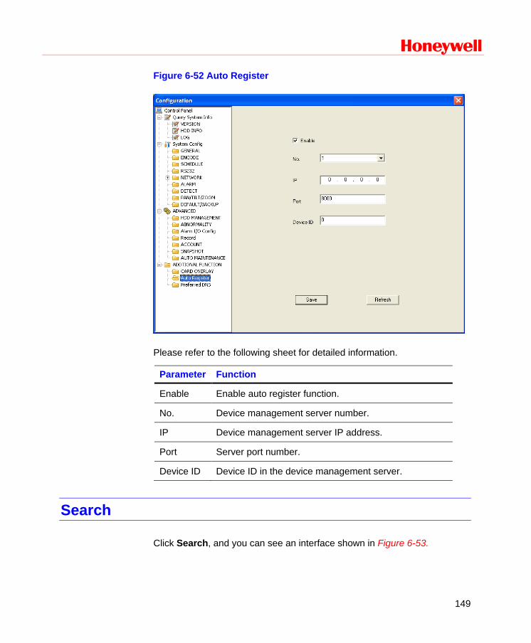
Honeywell
149
Figure 6-52 Auto Register
Please refer to the following sheet for detailed information.
Parameter Function
Enable Enable auto register function.
No. Device management server number.
IP Device management server IP address.
Port Server port number.
Device ID Device ID in the device management server.
Search
Click Search, and you can see an interface shown in Figure 6-53.
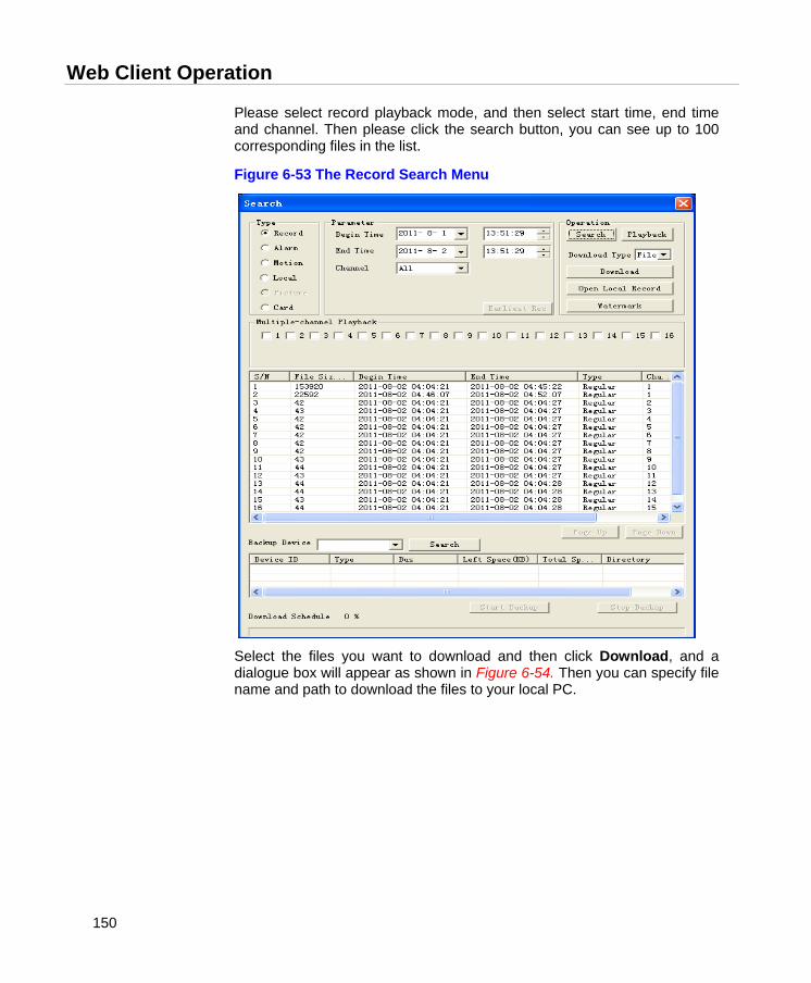
Web Client Operation
150
Please select record playback mode, and then select start time, end time and channel. Then please click the search button, you can see up to 100 corresponding files in the list.
Figure 6-53 The Record Search Menu
Select the files you want to download and then click Download, and a dialogue box will appear as shown in Figure 6-54. Then you can specify file name and path to download the files to your local PC.
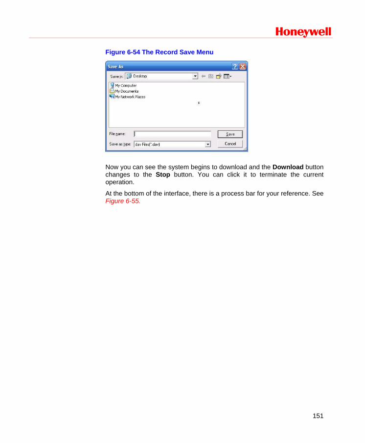
Honeywell
151
Figure 6-54 The Record Save Menu
Now you can see the system begins to download and the Download button changes to the Stop button. You can click it to terminate the current operation.
At the bottom of the interface, there is a process bar for your reference. See Figure 6-55.
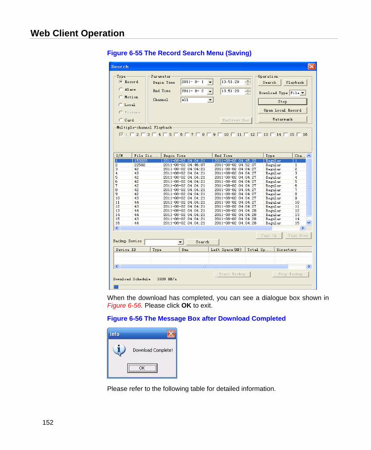
Web Client Operation
152
Figure 6-55 The Record Search Menu (Saving)
When the download has completed, you can see a dialogue box shown in Figure 6-56. Please click OK to exit.
Figure 6-56 The Message Box after Download Completed
Please refer to the following table for detailed information.
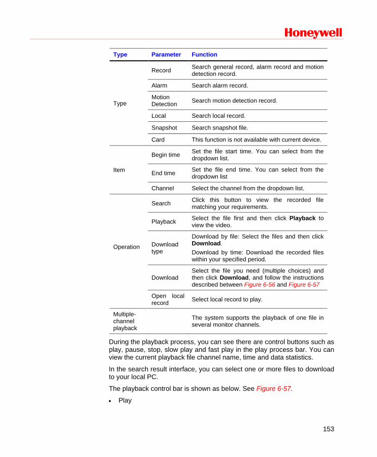
Honeywell
153
Type Parameter Function
Type
Record Search general record, alarm record and motion detection record.
Alarm Search alarm record.
Motion Detection Search motion detection record.
Local Search local record.
Snapshot Search snapshot file.
Card This function is not available with current device.
Item
Begin time Set the file start time. You can select from the dropdown list.
End time Set the file end time. You can select from the dropdown list
Channel Select the channel from the dropdown list.
Operation
Search Click this button to view the recorded file matching your requirements.
Playback Select the file first and then click Playback to view the video.
Download type
Download by file: Select the files and then click Download. Download by time: Download the recorded files within your specified period.
Download Select the file you need (multiple choices) and then click Download, and follow the instructions described between Figure 6-56 and Figure 6-57
Open local record Select local record to play.
Multiple-channel playback
The system supports the playback of one file in several monitor channels.
During the playback process, you can see there are control buttons such as play, pause, stop, slow play and fast play in the play process bar. You can view the current playback file channel name, time and data statistics.
In the search result interface, you can select one or more files to download to your local PC.
The playback control bar is shown as below. See Figure 6-57.
• Play

Web Client Operation
154
• Pause
• Stop
• Slow play
• Fast play
Figure 6-57 The Playback Menu
Alarm
Click alarm function, and you can see an interface as shown in Figure 6-58.
Here you can set device alarm type and alarm sound setup.
The IP address of playback device and channel number.
Playback control bar
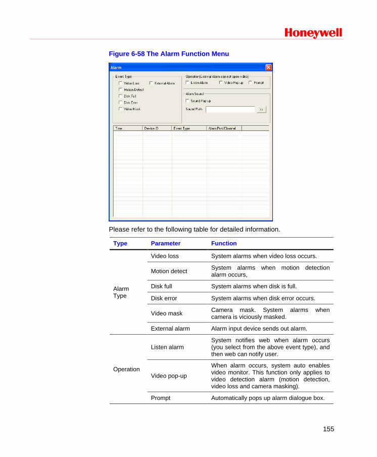
Honeywell
155
Figure 6-58 The Alarm Function Menu
Please refer to the following table for detailed information.
Type Parameter Function
Alarm Type
Video loss System alarms when video loss occurs.
Motion detect System alarms when motion detection alarm occurs,
Disk full System alarms when disk is full.
Disk error System alarms when disk error occurs.
Video mask Camera mask. System alarms when camera is viciously masked.
External alarm Alarm input device sends out alarm.
Operation
Listen alarm System notifies web when alarm occurs (you select from the above event type), and then web can notify user.
Video pop-up
When alarm occurs, system auto enables video monitor. This function only applies to video detection alarm (motion detection, video loss and camera masking).
Prompt Automatically pops up alarm dialogue box.
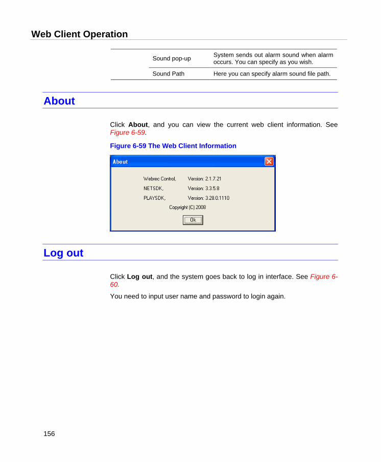
Web Client Operation
156
Sound pop-up System sends out alarm sound when alarm occurs. You can specify as you wish.
Sound Path Here you can specify alarm sound file path.
About
Click About, and you can view the current web client information. See Figure 6-59.
Figure 6-59 The Web Client Information
Log out
Click Log out, and the system goes back to log in interface. See Figure 6-60.
You need to input user name and password to login again.
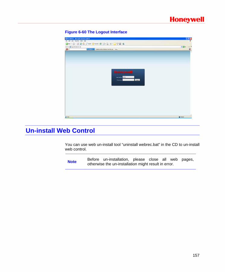
Honeywell
157
Figure 6-60 The Logout Interface
Un-install Web Control
You can use web un-install tool “uninstall webrec.bat” in the CD to un-install web control.
Note Before un-installation, please close all web pages, otherwise the un-installation might result in error.
FAQ
158
7 FAQ
1. DVR cannot boot up properly.
There are the following possibilities:
• Input power is incorrect.
• Power connection is incorrect.
• Power switch button is damaged.
• Program upgrade is wrong.
• HDD malfunction or something is wrong with HDD ribbon.
• Front panel error.
• Main board is damaged.
2. DVR often automatically shuts down or stops running.
There are the following possibilities:
• Input voltage is not stable or it is too low.
• HDD malfunction or something wrong with the ribbon.
• Button power is not enough.
• Front video signal is not stable.
• Working environment is too harsh, too much dust.
• Hardware malfunction.
3. System can not detect hard disk.
There are the following possibilities:
• HDD is broken.
• HDD ribbon is damaged.
• HDD cable connection is loose.
• Main board SATA port is broken.
Honeywell
159
4. There is no video output whether it is one-channel, multiple-channel or all-channel output.
There are the following possibilities:
• Program is incompatible. Please upgrade to the latest version.
• Brightness is 0. Please restore factory default setup.
• There is no video input signal or it is too weak.
• Check privacy mask setup or your screen saver.
• DVR hardware malfunctions.
5. Real-time video color is distorted.
There are the following possibilities:
• When using BNC output, NTSC and PAL setup is not correct. The real-time video becomes black and white.
• DVR and monitor resistance is not compatible.
• Video transmission distance is too long or video signal is too much degraded.
• DVR color or brightness setup is incorrect.
6. Can not search local records.
There are the following possibilities:
• HDD ribbon is damaged.
• HDD is broken.
• Upgraded program is not compatible.
• The recorded file has been overwritten.
• Record function has been disabled.
7. Video is distorted when searching local records.
There are the following possibilities:
• Video quality setup is too low.
FAQ
160
• Program read error, bit data is too small. There is a mosaic displayed on the full screen. Please restart the DVR to solve this problem.
• HDD data ribbon error.
• HDD malfunction.
• DVR hardware malfunctions.
8. There is no audio when live monitoring.
There are the following possibilities:
• The audio source is not a power picker.
• The audio output is not connected to a power speaker.
• Audio cable is damaged.
• DVR hardware malfunctions.
9. There is audio when monitoring, but there is no audio when system enters playback mode.
There are following possibilities:
• Setup is not correct. Please enable audio function
• Corresponding channel has no video input. Playback is not continuous when the screen is blue.
10. Time display is not correct.
There are the following possibilities:
• Setup is not correct
• Battery contact is not correct or voltage is too low.
• Crystal is broken.
11. DVR cannot control PTZ.
There are the following possibilities:
• Front panel PTZ error
• PTZ decoder setup, connection or installation is incorrect.
• Cable connection is incorrect.
• PTZ setup is incorrect.
Honeywell
161
• PTZ decoder and DVR protocol is incompatible.
• PTZ decoder and DVR address is incompatible.
• When there are several decoders, please add 120 Ohm (impedance matching) between the PTZ decoder A/B cables’ farthest end to delete the reverberation. Otherwise the PTZ control is not stable.
• The distance is too far.
12. Motion detection function does not work.
There are the following possibilities:
• Period setup is incorrect.
• Motion detection zone setup is incorrect.
• Sensitivity is too low.
• For some versions, there is a hardware limit.
13. Cannot log in client-end or web.
There are the following possibilities:
• For Windows 98 or Windows ME user, please update your system to Windows 2000 sp4. You can also install client-end software of a previous version. Please note right now, our DVR is not compatible with Windows VISTA control.
• ActiveX control has been disabled.
• No dx8.1 or higher. Please upgrade display card driver.
• Network connection error.
• Network setup error.
• Password or user name is invalid.
• Client-end is not compatible with DVR program.
14. Only a mosaic is displayed, no video appears when preview or playback video are filed remotely.
There are following possibilities:
• Network fluency is not good.
• Client-end resources are limited.
FAQ
162
• There is multiple-cast group setup in DVR. This mode can result in a mosaic appearance. Usually we do not recommend this mode.
• There is privacy mask or channel protection setup.
• Current user has no right to monitor.
• DVR local video output quality is not good.
15. Network connection is not stable.
There are following possibilities:
• Network is not stable.
• IP address conflict.
• MAC address conflict.
• PC or DVR network card is not good.
16. Burn error /USB back error.
There are the following possibilities:
• Burner and DVR are in the same data cable.
• System uses too many CPU resources. Please stop recording first and then begin backup.
• Data amount exceeds backup device capacity. It may result in burner error.
• Backup device is not compatible.
• Backup device is damaged.
17. Keyboard cannot control DVR.
There are the following possibilities:
• DVR serial port setup is incorrect.
• Address is incorrect.
• When there are several switchers, power supply is not enough.
• Transmission distance is too far.
18. Alarm signal cannot been disarmed.
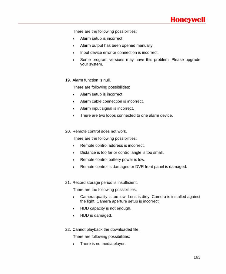
Honeywell
163
There are the following possibilities:
• Alarm setup is incorrect.
• Alarm output has been opened manually.
• Input device error or connection is incorrect.
• Some program versions may have this problem. Please upgrade your system.
19. Alarm function is null.
There are following possibilities:
• Alarm setup is incorrect.
• Alarm cable connection is incorrect.
• Alarm input signal is incorrect.
• There are two loops connected to one alarm device.
20. Remote control does not work.
There are the following possibilities:
• Remote control address is incorrect.
• Distance is too far or control angle is too small.
• Remote control battery power is low.
• Remote control is damaged or DVR front panel is damaged.
21. Record storage period is insufficient.
There are the following possibilities:
• Camera quality is too low. Lens is dirty. Camera is installed against the light. Camera aperture setup is incorrect.
• HDD capacity is not enough.
• HDD is damaged.
22. Cannot playback the downloaded file.
There are following possibilities:
• There is no media player.

FAQ
164
• No DirectX 8.1 or higher graphic acceleration software is installed. Please install the latest DirectX software.
• There is no DivX503Bundle.exe control when you play the file transformed to AVI via media player.
• No DivX503Bundle.exe or ffdshow-2004 1012 .exe in Windows XP OS.
23. Forgot local menu operation password or network password
Please contact your local service engineer or our sales person for help. We can guide you to solve this problem.
Slight difference may be found in user interface.
All the designs and software here are subject to change without prior written notice.
Please visit our website for more information.
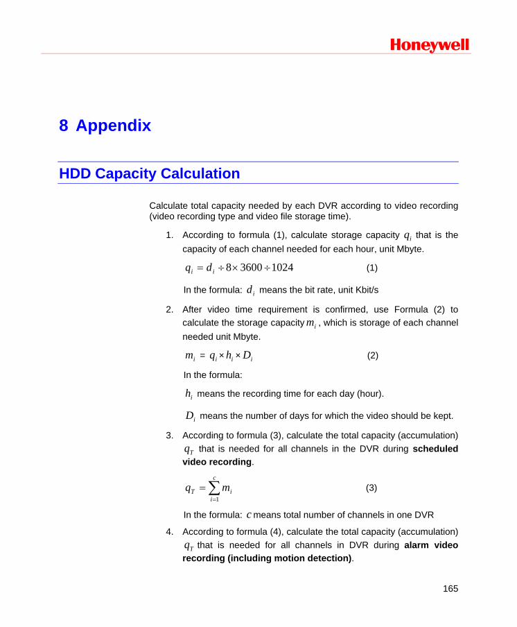
Honeywell
165
8 Appendix
HDD Capacity Calculation
Calculate total capacity needed by each DVR according to video recording (video recording type and video file storage time).
1. According to formula (1), calculate storage capacity iq that is the capacity of each channel needed for each hour, unit Mbyte.
102436008 ÷×÷= ii dq (1)
In the formula: id means the bit rate, unit Kbit/s
2. After video time requirement is confirmed, use Formula (2) to calculate the storage capacity im , which is storage of each channel needed unit Mbyte.
im = iq × ih × iD (2)
In the formula:
ih means the recording time for each day (hour).
iD means the number of days for which the video should be kept.
3. According to formula (3), calculate the total capacity (accumulation)
Tq that is needed for all channels in the DVR during scheduled video recording.
∑=
=c
iiT mq
1
(3)
In the formula: c means total number of channels in one DVR
4. According to formula (4), calculate the total capacity (accumulation)
Tq that is needed for all channels in DVR during alarm video recording (including motion detection).
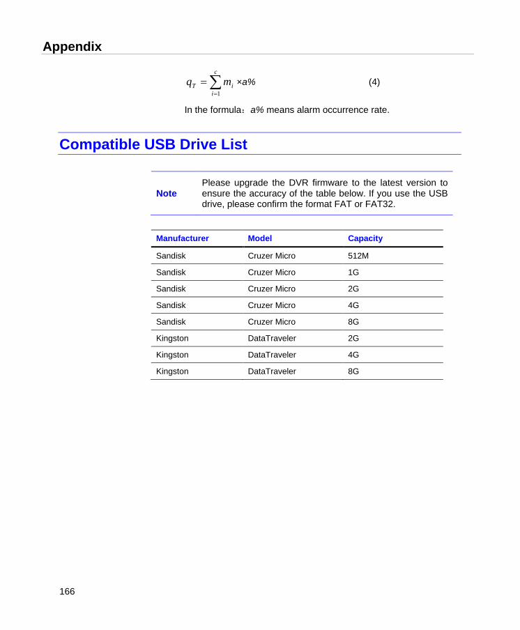
Appendix
166
∑=
=c
iiT mq
1
×a% (4)
In the formula:a% means alarm occurrence rate.
Compatible USB Drive List
Note Please upgrade the DVR firmware to the latest version to ensure the accuracy of the table below. If you use the USB drive, please confirm the format FAT or FAT32.
Manufacturer Model Capacity
Sandisk Cruzer Micro 512M
Sandisk Cruzer Micro 1G
Sandisk Cruzer Micro 2G
Sandisk Cruzer Micro 4G
Sandisk Cruzer Micro 8G
Kingston DataTraveler 2G
Kingston DataTraveler 4G
Kingston DataTraveler 8G


Honeywell Security Honeywell Security Asia Pacific 35F Tower A, City Center, 100 Zun Yi Road, Shanghai 200051, China TEL +86 21 22196888 FAX +86 21 62370740 Honeywell Security (China) Co., Ltd. Block 28, Section 2 Huai De Cui Gang Industrial Estate Fu Yong, Bao An, Shenzhen, P.R.China TEL +86 0755 27326500 FAX +86 0755 27391736
© 2011 Honeywell International Inc. http://www.security.honeywell.com


![Hd dvr-1016[1]](https://img.pdfslide.net/doc/110x75/5555fde5d8b42a8a5f8b530c/hd-dvr-10161.jpg)
![Hd dvr-1004[1]](https://img.pdfslide.net/doc/110x75/5555febdd8b42a3f168b45a4/hd-dvr-10041.jpg)