Embed Size (px)
Citation preview

U.S. Department of EnergyNational Energy Technology Laboratory
Addressing the Nation’s Energy Needs Through Technology Innovation – 2019 Carbon Capture, Utilization, Storage, and Oil and Gas Technologies Integrated Review Meeting
August 26-30, 2019
LBNL – FP00008137 Behavior of Sediments Containing Methane Hydrate,
Water, and Gas Subjected to Gradients and Changing Conditions
Tim Kneafsey, Sharon Borglin, Seiji NakagawaPresented by Matt Reagan
Energy Geosciences Division, Earth and Environmental Sciences Area, Lawrence Berkeley National Laboratory
This research is supported by theAssistant Secretary for Fossil Energy, Office of Natural Gas and Petroleum Technology through the National Energy Technology Laboratory Under the
U.S. DOE Contract No. DE-AC02-05CH11231

Presentation Outline
Technical Statuso Motivation & Backgroundo Goal and Objectiveso Anticipated Products and Impactso Project Tasks and Activitieso Results so far
Accomplishment to Date Lesson Learned Synergy Opportunities Project Summary

Motivation and Background
Support evaluation and simulation of the recovery of gas from natural gas hydrate via laboratory investigation• Measure physical, chemical, mechanical, and hydrologic
property changes in sediments containing methane hydrate, water, and gas subjected to varying stimuli and conditions.
• effects of of other gases (CO2, N2, mixtures)• effects of sediment layering• effects of stress• effects of relevant gradients [thermal, chemical (salinity or
gas composition), and capillary pressure] on hydrate behavior.
• All tests are non-standard and new techniques must be developed.

Project Goals/Objectives• Evaluate the mechanical properties of hydrate-bearing sediments under
controlled conditions to provide data sets for comparisons to numerical models.
• Measurements performed in this project are designed to supplement and support field and numerical simulation investigations to provide benchmark measurements and reality checks.
Modeled cases (Lab cases)Case 1: No Hydrate Formation• Pressure [MPa] versus time at z/L = 0.005, 0.405, 0.605, 0.995• Z-Displacement versus time at z/L = 1.0Case 2: Hydrate Formation and Dissociation• Pressure [MPa] versus time at z/L = 0.005, 0.405, 0.605, 0.995• Temperature [˚C] versus time at z/L = 0.005, 0.405, 0.605, 0.995• Hydrate Saturation versus time at z/L = 0.005, 0.405, 0.605, 0.995• Z-Displacement versus time at z/L = 1.0Case 3: Hydrate Dependent Shear Modulus• Pressure [MPa] versus time at z/L = 0.005, 0.405, 0.605, 0.995• Temperature [˚C] versus time at z/L = 0.005, 0.405, 0.605, 0.995• Hydrate Saturation versus time at z/L = 0.005, 0.405, 0.605, 0.995• Z-Displacement versus time at z/L = 1.0Case 4: Rapid Hydrate Kinetics• Pressure [MPa] versus time at z/L = 0.005, 0.405, 0.605, 0.995• Temperature [˚C] versus time at z/L = 0.005, 0.405, 0.605, 0.995• Hydrate Saturation versus time at z/L = 0.005, 0.405, 0.605, 0.995• Z-Displacement versus time at z/L = 1.0

Anticipated Products and Impacts
Products:• New experimental tool (1-D stress/strain) and
methodology for measuring and visualizing time and stress-dependent compaction of hydrate-bearing samples
• Laboratory data on stress-dependent compaction of hydrate-bearing samples
• New observations of system behavior

Technical Status
• Task 1.0 Project Management Plan• Task 2. Laboratory benchmark geomechanical tests for code
validation• 2a. Design the task with feedback from geomechanical
modelers• 2b. Test design and construction with existing or off-the-
shelf pressure equipment• 2c Perform a series of tests (cementing hydrate)• 2d. Devise transfer method/sample composition for pore-
filling hydrate• 2e. Perform tests on pore-filling hydrate

Results So Far
Evaluated techniques as enabled by laboratory capabilities and funding
Keys:• Accurately measure 1-D length change in response to loading
• Ability to control pressuretemperatureflow of waterflow of gashydrate formationsample Very complex system, time consuming and expensive
Designed simple consolidometer to operate inside X-ray-transparent pressure vessel
Uthayakumar, M & Vaid, Yogi. (2011)
Use rigid sleeve with fixed platen and floating piston

Evaluate 1-D length measurements (consolidation) under hydrate P, T, X conditions
Issues• P, T control difficult in large systems• Waterproof high pressure LVDT?• X-ray CT?• Best resolution on our medical X-ray CT scanner is
0.193 mm x 0.193 mm x 0.625 mm. Subvoxel resolution needed.
Results So Far
Too coarse
Can we do better?

– Could use • Different scanner ($)• Special table ($) and data reconstruction
– Develop technique for X-ray CT sub-voxel length measurements
• Take advantage of higher resolution in x-ydirections and geometry
• Enhance axial length resolution• Initial concepts include
– Vernier-type setups (need to alter angle of sample or internal standard)
– Screw threads
Results So Far

“New” concept – the inclined plane
Small axial translation yields large signal on CT plane
CT “slice” planeFixed platen Floating piston
• Use slanted X-ray visible coupon in platen and piston
• Axial displacement is shown as lateral displacement and sensitivity is controlled by angle of coupon
Rigid Sleeve
Results So Far

Rigid sleeve system
• Thin wall aluminum tube machined and polished
• Rigid enough? -difference CT scans show it is
Results So Far

Vessel Setup
Results So Far

Stack Registration
• Stack registration (alignment) must be precise or registration errors will overwhelm measurements
• New technique devised modifying existing methods.
Image from Stack 1 Image from Stack 2
Subtraction (poorly registered)
Subtraction (well registered)
Results So Far

Analysis Method
• Once precisely registered, a profile of CT values is obtained from the exact same location from each stack across the coupon, and the profiles compared.
• The distance required to align the profiles considering the angle of the incline is used to compute distance translated.
• Both the platen and the piston must be evaluated to quantify total length change. Sh
ifted
Late
ral s
hift
Results So Far
Location of profile

Examples of test results• F110 sand with 5% by mass kaolinite• Moisture to reach 30% saturation• Nearly full hydrate conversion, fairly
uniform
• F110 sand with 5% by mass kaolinite• Moisture to reach 30% saturation• No hydrate
Initial Compaction
Large initial compaction settling to stiffer medium
Hydrate-bearing sediment stiffer (lower slope) than without hydrate
Results So Far
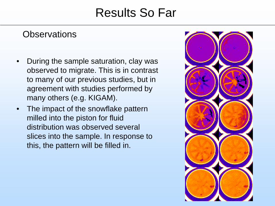
Observations
• During the sample saturation, clay was observed to migrate. This is in contrast to many of our previous studies, but in agreement with studies performed by many others (e.g. KIGAM).
• The impact of the snowflake pattern milled into the piston for fluid distribution was observed several slices into the sample. In response to this, the pattern will be filled in.
Results So Far
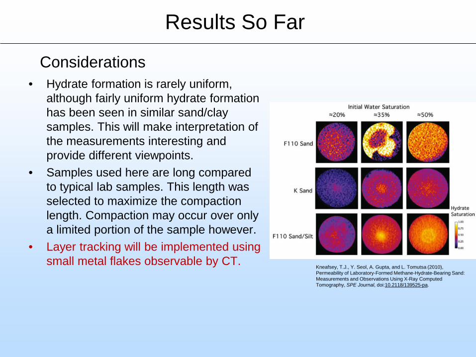
Considerations• Hydrate formation is rarely uniform,
although fairly uniform hydrate formation has been seen in similar sand/clay samples. This will make interpretation of the measurements interesting and provide different viewpoints.
• Samples used here are long compared to typical lab samples. This length was selected to maximize the compaction length. Compaction may occur over only a limited portion of the sample however.
• Layer tracking will be implemented using small metal flakes observable by CT.
Kneafsey, T.J., Y. Seol, A. Gupta, and L. Tomutsa (2010), Permeability of Laboratory-Formed Methane-Hydrate-Bearing Sand: Measurements and Observations Using X-Ray Computed Tomography, SPE Journal, doi:10.2118/139525-pa.
Results So Far

• A consolidometer was constructed that allows the measurement of strain on hydrate-bearing samples.
• Strain is computed from X-ray CT scans, using a custom platen and piston containing aluminum coupons at angles to the axis of the scanning. These allow computation of voxel-thickness displacements.
• Precise image registration is required to employ this strategy. To allow for this, a new technique was devised and employed, that was very successful. Adding to the success was the refined usage of the CT scanner itself.
• Two other techniques are under consideration to improve and make the displacement measurements more accurate and automatic. Displayed using Volume Viewer
Accomplishments to Date

Lessons Learned
• The hydrate bearing sediment used in shakedown tests was much stiffer than the non-hydrate bearing sediment (as expected).
• The X-ray CT techniques developed provide fairly sensitive displacement indications.
• Data analysis techniques developed here have resolved image registration and sample displacement issues.

Synergy Opportunities
– Collaboration is expected with researchers at NETL, KIGAM, and other institutions who have been frustrated by problems resolved under this project.
– Discussion of measurements and goals of the project with the International Gas Hydrate Code Comparison Team introduced ideas for collaborative work with NETL and Rensselaer Polytechnic Institute.
– Collaborative discussions with USGS and AIST have already occurred resulting in improvements in the design and experiment plan.
20

Continued Work
• Continue measurements with layer indicators for compaction vs depth
• Perform and compare experiments on cementing and pore filling/supporting hydrate-bearing sediments
• Develop automatic method to compute distance change
Consider:• Properties of Alaska test site and determine
applicability of new tests to support/understand processes

Appendix
22
Project Summary
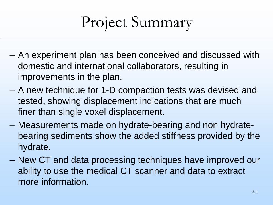
– An experiment plan has been conceived and discussed with domestic and international collaborators, resulting in improvements in the plan.
– A new technique for 1-D compaction tests was devised and tested, showing displacement indications that are much finer than single voxel displacement.
– Measurements made on hydrate-bearing and non hydrate-bearing sediments show the added stiffness provided by the hydrate.
– New CT and data processing techniques have improved our ability to use the medical CT scanner and data to extract more information.
23

24
Benefit to the Program
Program GoalsThe ultimate goal of the Gas Hydrate Program is to determine the conditions under which natural gas can be produced from hydrate-bearing sediments. The tools in use by the program include field tests, numerical simulations, and laboratory tests.Project BenefitsThis project provides important information for interpreting field tests quantifying the importance of the mechanical behavior, natural and imposed thermal, chemical, or capillary pressure gradients, and impacts on hydrological of hydrate-bearing sediments. Questions asked and answered on this project will be from a reservoir perspective understanding that many nonideal conditions can exist.
Organization Chart
Project TeamHelen Prieto
–Administrative Assistance–
Tim Kneafsey, Sharon Borglin, Seiji Nakagawa, Chun Chang
–Lab and data analysis–

26
Gantt Chart

Bibliography
For the current research project, publications are still in preparation
27


![A conduit dilation model of methane venting from lake ...web.mit.edu/hemond/www/docs/conduit_dilation_model.pdfcontrols ebullition from lake sediments. 2. Model Formulation [5] Methane](https://img.pdfslide.net/doc/110x75/5f7cf4de3b2572106a6ce8e3/a-conduit-dilation-model-of-methane-venting-from-lake-webmiteduhemondwwwdocsconduitdilationmodelpdf.jpg)