Embed Size (px)
Citation preview

LCC Pump Series - Wear Resistant, High Performance Slurry Pumps
02
The LCC Pump family is recommended for
applications with coarse or fine particles from
solids-laden waste to agressive slurries of an
abrasive and/or corrosive nature.
LCC’s rugged design features, combined with
shell, impeller and liner in our proprietary
Gasite® material, are recognized worldwide
for superior abrasion resistance. In addition,
several impeller options to fine tune pump
performance, and customized pumping needs
are available. These options allow optimum
wear life and sustained efficiency.
For high performance and low maintenance
the wet end consists of three components: a
shell or casing, an impeller that screws onto
the shaft and a suction plate/liner to permit
easy assembly and disassembly for maintenance
and inspections.
Actual Photo: LCC-R in service at a metals processing plant in Mexico.
Solutions for the most Abrasive and Corrosive Slurry Applications
With High Performance Wear Resistance, the GIW® Minerals LCC Pump family withstands the most severe slurry applications.
LCC Pump Series
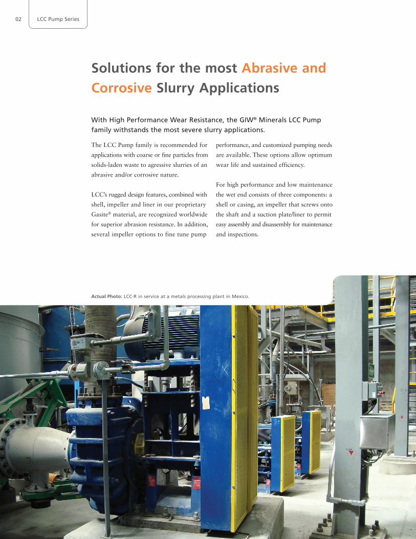
Choose the GIW® Minerals LCC Pump for Agressive Slurries
Wear Resistant Wet End Parts
■ Advanced metallurgy provides Wear Resistant alloys
tailored to meet virtually any slurry pumping condition.
Advanced Hydraulic Design
■ Uses the latest technology tried and tested in our
Hydraulic
Laboratory and in the field.
Single Wall Hard Metal shell
■ CAD designed shell and replaceable suction plate/liner
■ Interchangeable sizes with 2 pedestals and 4 mechanical
ends
■ Alloys available for difficult chemical applications
Rubber Lined
■ Precision molded rubber parts
■ Bolt in liners for easy maintenance
■ CNC machined ductile iron casings
■ 2-stage operating pressure capacity up to 230 psi (16
bar)
Extra Heavy Hard Metal
■ Heavier metal sections and hydraulics suited to severe
duties
■ 2-stage operating pressure capacity up to 230 psi (16
bar)
■ Separate suction liner and non-wearing plate
(lower replacement cost)
■ Available in sizes 150-500 (6" x 20") and above
High Pressure Hard Metal
■ Discharge sizes range from 50 mm to 200 mm
■ 3-Stage operating pressure capacity up to 350 psig (24 bar)
■ Separate suction liner an non-wearing plate 80 to 250
mm (3"to 10")
Impellers (metal/rubber)
■ Twisted three vane design provides high efficiency and
low net positive suction head requirements
■ Maximum sphere passage
■ Available in various materials including GIW Minerals
alloys, polyurethane and extreme duty versions
Technical Data
Discharge 2 to 12 in (50 to 300 mm) *High Pressure 2 to 8 in (50 to 200 mm)
Flow rates up to 15,000 gpm (3,405m3/h)
Total head up to 300 ft (90 m)
Power rating up to 750 Hp (560 kW)
Temperature limit up to 248°F (+120°C)
Applications
■ Chemical Slurry Service ■ Mineral Processing ■ Sand and Gravel ■ Tailings
■ Fine Primary Mill Grinding ■ Secondary Grinding ■ In-plant Processes ■ Coal Preparation
Also available in rubber
■ Interchangeable with existing metal impellers used in
earlier LCC-R pumps
■ Designed with proven advanced hydraulics
■ Best wear resistant rubber on the market
■ Thickened shrouds and vanes provide maximum wear
resistance in heavier slurries
Cartridge Bearing Assembly
■ CNC machined cast iron cylindrical housing
■ Double row tapered roller bearings handle mechanical
and thrust forces
■ INPRO® Bearing Isolators are standard
■ Oil or grease lubrication
Pedestal
■ CNC machined cast iron
■ Self-aligning concentric bearing supports
■ Integrated impeller gap adjustment screw
■ Two pedestal sizes for entire LCC range
03Design Features
04
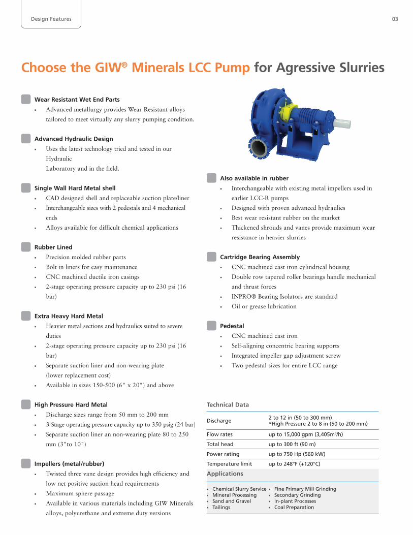
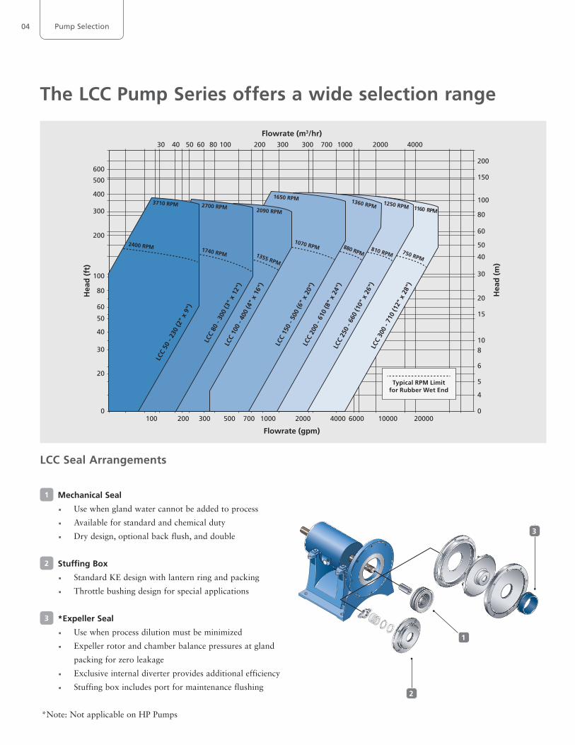
The LCC Pump Series offers a wide selection range
30 40 50 60 80 100 200 300 300
100 200 300 500 700 1000 2000 4000 6000 10000 20000
700 1000 2000 4000
200
150
100
80
60
50
40
30
20
15
108
6
5
4
0
500
600
400
300
200
100
80
60
50
40
30
20
0
Flowrate (m3/hr)
Flowrate (gpm)
Hea
d (
ft)
Hea
d (
m)
LCC
50 -
230
(2"
x 9"
)
LCC
80 -
300
(3"
x 12
")
LCC
100
- 400
(4"
x 16
")
LCC
150
- 500
(6"
x 20
")LC
C 20
0 - 6
10 (8
" x
24")
LCC
250
- 660
(10"
x 2
6")
LCC
300
- 710
(12"
x 2
8")
2400 RPM 1740 RPM 1355 RPM
1070 RPM 880 RPM810 RPM 750 RPM
3710 RPM 2700 RPM 2090 RPM
1650 RPM 1360 RPM 1250 RPM 1160 RPM
Typical RPM Limitfor Rubber Wet End
LCC Seal Arrangements
1 Mechanical Seal
■ Use when gland water cannot be added to process
■ Available for standard and chemical duty
■ Dry design, optional back flush, and double
2 Stuffing Box
■ Standard KE design with lantern ring and packing
■ Throttle bushing design for special applications
3 *Expeller Seal
■ Use when process dilution must be minimized
■ Expeller rotor and chamber balance pressures at gland
packing for zero leakage
■ Exclusive internal diverter provides additional efficiency
■ Stuffing box includes port for maintenance flushing
*Note: Not applicable on HP Pumps
1
3
2
Pump Selection
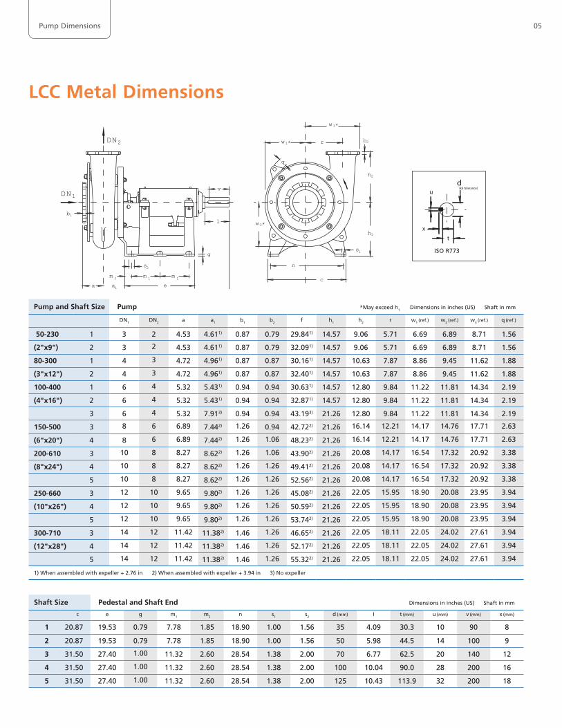
LCC Metal Dimensions
Pump and Shaft Size Pump *May exceed h1 Dimensions in inches (US) Shaft in mm
DN1 DN2 a a1 b1 b2 f h1 h2 r w1 (ref.) w2 (ref.) w3 (ref.) q (ref.)
50-230 1 3 2 4.53 4.611) 0.87 0.79 29.841) 14.57 9.06 5.71 6.69 6.89 8.71 1.56
(2"x9") 2 3 2 4.53 4.611) 0.87 0.79 32.091) 14.57 9.06 5.71 6.69 6.89 8.71 1.56
80-300 1 4 3 4.72 4.961) 0.87 0.87 30.161) 14.57 10.63 7.87 8.86 9.45 11.62 1.88
(3"x12") 2 4 3 4.72 4.961) 0.87 0.87 32.401) 14.57 10.63 7.87 8.86 9.45 11.62 1.88
100-400 1 6 4 5.32 5.431) 0.94 0.94 30.631) 14.57 12.80 9.84 11.22 11.81 14.34 2.19
(4"x16") 2 6 4 5.32 5.431) 0.94 0.94 32.871) 14.57 12.80 9.84 11.22 11.81 14.34 2.19
3 6 4 5.32 7.913) 0.94 0.94 43.193) 21.26 12.80 9.84 11.22 11.81 14.34 2.19
150-500 3 8 6 6.89 7.442) 1.26 0.94 42.722) 21.26 16.14 12.21 14.17 14.76 17.71 2.63
(6"x20") 4 8 6 6.89 7.442) 1.26 1.06 48.232) 21.26 16.14 12.21 14.17 14.76 17.71 2.63
200-610 3 10 8 8.27 8.622) 1.26 1.06 43.902) 21.26 20.08 14.17 16.54 17.32 20.92 3.38
(8"x24") 4 10 8 8.27 8.622) 1.26 1.26 49.412) 21.26 20.08 14.17 16.54 17.32 20.92 3.38
5 10 8 8.27 8.622) 1.26 1.26 52.562) 21.26 20.08 14.17 16.54 17.32 20.92 3.38
250-660 3 12 10 9.65 9.802) 1.26 1.26 45.082) 21.26 22.05 15.95 18.90 20.08 23.95 3.94
(10"x26") 4 12 10 9.65 9.802) 1.26 1.26 50.592) 21.26 22.05 15.95 18.90 20.08 23.95 3.94
5 12 10 9.65 9.802) 1.26 1.26 53.742) 21.26 22.05 15.95 18.90 20.08 23.95 3.94
300-710 3 14 12 11.42 11.382) 1.46 1.26 46.652) 21.26 22.05 18.11 22.05 24.02 27.61 3.94
(12"x28") 4 14 12 11.42 11.382) 1.46 1.26 52.172) 21.26 22.05 18.11 22.05 24.02 27.61 3.94
5 14 12 11.42 11.382) 1.46 1.26 55.322) 21.26 22.05 18.11 22.05 24.02 27.61 3.94
1) When assembled with expeller + 2.76 in 2) When assembled with expeller + 3.94 in 3) No expeller
Shaft Size Pedestal and Shaft End Dimensions in inches (US) Shaft in mm
c e g m1 m2 n s1 s2 d (mm) I t (mm) u (mm) v (mm) x (mm)
1 20.87 19.53 0.79 7.78 1.85 18.90 1.00 1.56 35 4.09 30.3 10 90 8
2 20.87 19.53 0.79 7.78 1.85 18.90 1.00 1.56 50 5.98 44.5 14 100 9
3 31.50 27.40 1.00 11.32 2.60 28.54 1.38 2.00 70 6.77 62.5 20 140 12
4 31.50 27.40 1.00 11.32 2.60 28.54 1.38 2.00 100 10.04 90.0 28 200 16
5 31.50 27.40 1.00 11.32 2.60 28.54 1.38 2.00 125 10.43 113.9 32 200 18
w3*
w2*
b2
s1
s2
a1
m 1m 1m 2
v
r
c
n
q
a e
f
g
lb1
DN1
DN2 w1*
h2
h1
ISO R773
x
d
t
u (k6 tolerance)
05Pump Dimensions
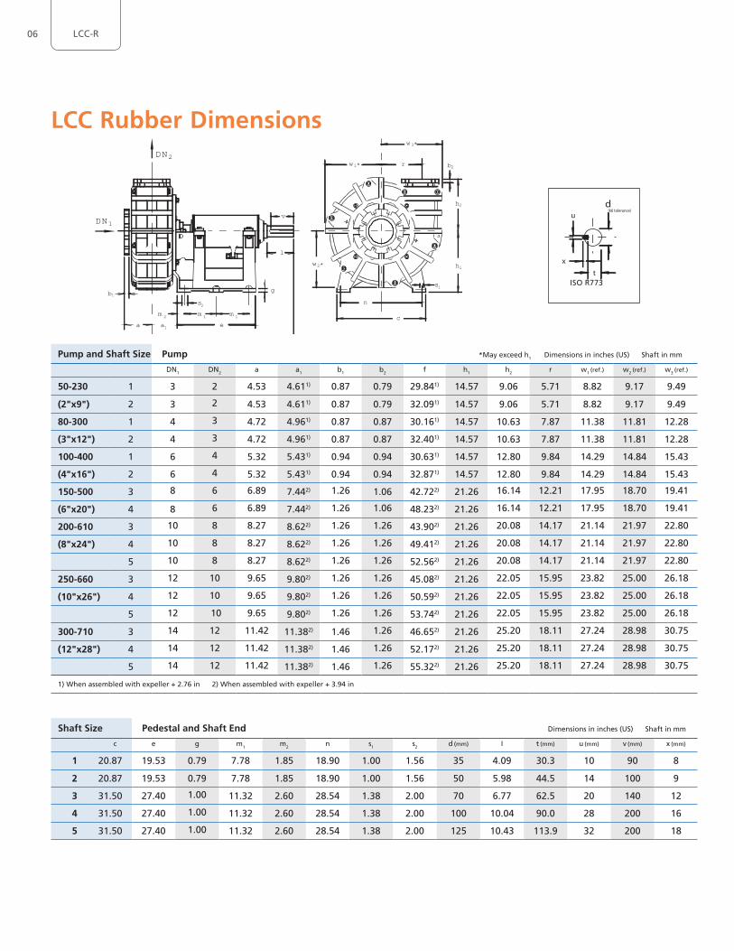
LCC Rubber Dimensions
Pump and Shaft Size Pump *May exceed h1 Dimensions in inches (US) Shaft in mm
DN1 DN2 a a1 b1 b2 f h1 h2 r w1 (ref.) w2 (ref.) w3 (ref.)
50-230 1 3 2 4.53 4.611) 0.87 0.79 29.841) 14.57 9.06 5.71 8.82 9.17 9.49
(2"x9") 2 3 2 4.53 4.611) 0.87 0.79 32.091) 14.57 9.06 5.71 8.82 9.17 9.49
80-300 1 4 3 4.72 4.961) 0.87 0.87 30.161) 14.57 10.63 7.87 11.38 11.81 12.28
(3"x12") 2 4 3 4.72 4.961) 0.87 0.87 32.401) 14.57 10.63 7.87 11.38 11.81 12.28
100-400 1 6 4 5.32 5.431) 0.94 0.94 30.631) 14.57 12.80 9.84 14.29 14.84 15.43
(4"x16") 2 6 4 5.32 5.431) 0.94 0.94 32.871) 14.57 12.80 9.84 14.29 14.84 15.43
150-500 3 8 6 6.89 7.442) 1.26 1.06 42.722) 21.26 16.14 12.21 17.95 18.70 19.41
(6"x20") 4 8 6 6.89 7.442) 1.26 1.06 48.232) 21.26 16.14 12.21 17.95 18.70 19.41
200-610 3 10 8 8.27 8.622) 1.26 1.26 43.902) 21.26 20.08 14.17 21.14 21.97 22.80
(8"x24") 4 10 8 8.27 8.622) 1.26 1.26 49.412) 21.26 20.08 14.17 21.14 21.97 22.80
5 10 8 8.27 8.622) 1.26 1.26 52.562) 21.26 20.08 14.17 21.14 21.97 22.80
250-660 3 12 10 9.65 9.802) 1.26 1.26 45.082) 21.26 22.05 15.95 23.82 25.00 26.18
(10"x26") 4 12 10 9.65 9.802) 1.26 1.26 50.592) 21.26 22.05 15.95 23.82 25.00 26.18
5 12 10 9.65 9.802) 1.26 1.26 53.742) 21.26 22.05 15.95 23.82 25.00 26.18
300-710 3 14 12 11.42 11.382) 1.46 1.26 46.652) 21.26 25.20 18.11 27.24 28.98 30.75
(12"x28") 4 14 12 11.42 11.382) 1.46 1.26 52.172) 21.26 25.20 18.11 27.24 28.98 30.75
5 14 12 11.42 11.382) 1.46 1.26 55.322) 21.26 25.20 18.11 27.24 28.98 30.75
1) When assembled with expeller + 2.76 in 2) When assembled with expeller + 3.94 in
Shaft Size Pedestal and Shaft End Dimensions in inches (US) Shaft in mm
c e g m1 m2 n s1 s2 d (mm) I t (mm) u (mm) v (mm) x (mm)
1 20.87 19.53 0.79 7.78 1.85 18.90 1.00 1.56 35 4.09 30.3 10 90 8
2 20.87 19.53 0.79 7.78 1.85 18.90 1.00 1.56 50 5.98 44.5 14 100 9
3 31.50 27.40 1.00 11.32 2.60 28.54 1.38 2.00 70 6.77 62.5 20 140 12
4 31.50 27.40 1.00 11.32 2.60 28.54 1.38 2.00 100 10.04 90.0 28 200 16
5 31.50 27.40 1.00 11.32 2.60 28.54 1.38 2.00 125 10.43 113.9 32 200 18
w3*
w2*
b2
s1
r
c
n
w1*
h2
h1
s2
a1
m 1m 2
v
a e
f
g
l
DN2
DN1
b1
m 1
ISO R773
x
d
t
u (k6 tolerance)
06 LCC-R
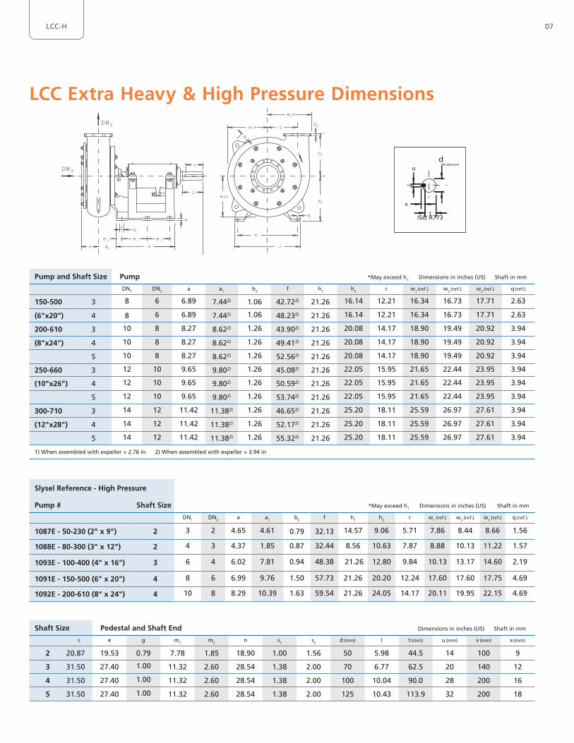
LCC Extra Heavy & High Pressure Dimensions
Pump and Shaft Size Pump *May exceed h1 Dimensions in inches (US) Shaft in mm
DN1 DN2 a a1 b2 f h1 h2 r w1 (ref.) w2 (ref.) w3 (ref.) q (ref.)
150-500 3 8 6 6.89 7.442) 1.06 42.722) 21.26 16.14 12.21 16.34 16.73 17.71 2.63
(6"x20") 4 8 6 6.89 7.442) 1.06 48.232) 21.26 16.14 12.21 16.34 16.73 17.71 2.63
200-610 3 10 8 8.27 8.622) 1.26 43.902) 21.26 20.08 14.17 18.90 19.49 20.92 3.94
(8"x24") 4 10 8 8.27 8.622) 1.26 49.412) 21.26 20.08 14.17 18.90 19.49 20.92 3.94
5 10 8 8.27 8.622) 1.26 52.562) 21.26 20.08 14.17 18.90 19.49 20.92 3.94
250-660 3 12 10 9.65 9.802) 1.26 45.082) 21.26 22.05 15.95 21.65 22.44 23.95 3.94
(10"x26") 4 12 10 9.65 9.802) 1.26 50.592) 21.26 22.05 15.95 21.65 22.44 23.95 3.94
5 12 10 9.65 9.802) 1.26 53.742) 21.26 22.05 15.95 21.65 22.44 23.95 3.94
300-710 3 14 12 11.42 11.382) 1.26 46.652) 21.26 25.20 18.11 25.59 26.97 27.61 3.94
(12"x28") 4 14 12 11.42 11.382) 1.26 52.172) 21.26 25.20 18.11 25.59 26.97 27.61 3.94
5 14 12 11.42 11.382) 1.26 55.322) 21.26 25.20 18.11 25.59 26.97 27.61 3.94
1) When assembled with expeller + 2.76 in 2) When assembled with expeller + 3.94 in
w3*
w2*
b2
s1
s2
a1
m 1m 1m 2
v
r
c
n
q
a e
f
g
l
DN1
DN2 w1*
h2
h1
ISO R773
x
d
t
u (k6 tolerance)
Shaft Size Pedestal and Shaft End Dimensions in inches (US) Shaft in mm
c e g m1 m2 n s1 s2 d (mm) I t (mm) u (mm) v (mm) x (mm)
2 20.87 19.53 0.79 7.78 1.85 18.90 1.00 1.56 50 5.98 44.5 14 100 9
3 31.50 27.40 1.00 11.32 2.60 28.54 1.38 2.00 70 6.77 62.5 20 140 12
4 31.50 27.40 1.00 11.32 2.60 28.54 1.38 2.00 100 10.04 90.0 28 200 16
5 31.50 27.40 1.00 11.32 2.60 28.54 1.38 2.00 125 10.43 113.9 32 200 18
Slysel Reference - High Pressure
Pump # Shaft Size *May exceed h1 Dimensions in inches (US) Shaft in mm
DN1 DN2 a a1 b2 f h1 h2 r w1 (ref.) w2 (ref.) w3 (ref.) q (ref.)
1087E - 50-230 (2" x 9") 2 3 2 4.65 4.61 0.79 32.13 14.57 9.06 5.71 7.86 8.44 8.66 1.56
1088E - 80-300 (3" x 12") 2 4 3 4.37 1.85 0.87 32.44 8.56 10.63 7.87 8.88 10.13 11.22 1.57
1093E - 100-400 (4" x 16") 3 6 4 6.02 7.81 0.94 48.38 21.26 12.80 9.84 10.13 13.17 14.60 2.19
1091E - 150-500 (6" x 20") 4 8 6 6.99 9.76 1.50 57.73 21.26 20.20 12.24 17.60 17.60 17.75 4.69
1092E - 200-610 (8" x 24") 4 10 8 8.29 10.39 1.63 59.54 21.26 24.05 14.17 20.11 19.95 22.15 4.69
07LCC-H
GIW Industries, Inc. (A KSB Company)5000 Wrightsboro Road, GrovetownGeorgia 30813-2842, USAwww.giwindustries.com 23
68.0
24-U
S / 1
1.15
/ ©
GIW
Ind
ust
ries
, In
c. 2
015
· Su
bje
ct t
o t
ech
nic
al m
od
ific
atio
ns.