Embed Size (px)
Citation preview
INSTRUCTION MANUAL INSTRUCTION MANUAL INSTRUCTION MANUAL INSTRUCTION MANUAL
ORIGINAL AUTHENTIC
ted produen ctat s,Png noteiti arf llte on wu eo dC
ORIGINAL AUTHENTIC
REV1.0
Your excellent helper in cable test!
LCD Network & Length Tester
MODEL:NF-8200
Your excellent helper in cable test!
SHENZHEN NOYAFA ELECTRONIC CO.,LTD
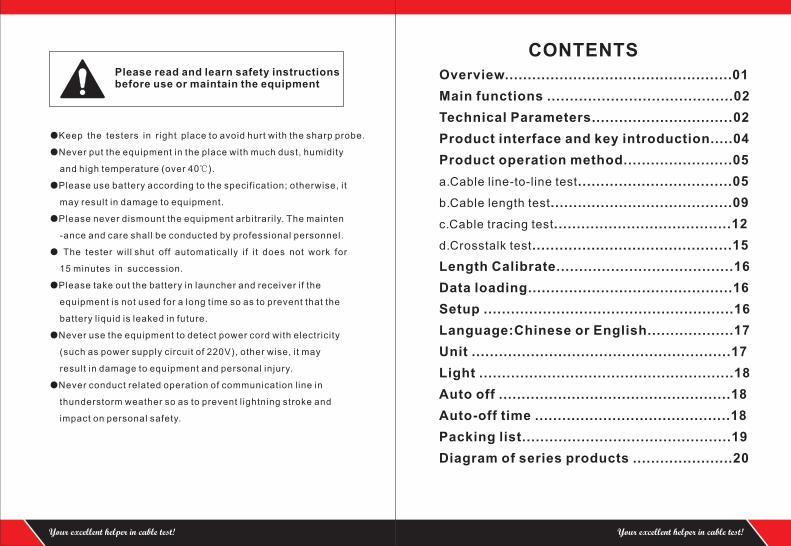
Please read and learn safety instructions before use or maintain the equipment
●Keep the testers in r ight place to avoid hurt with the sharp probe.
●Never put the equipment in the place with much dust, humidity
and high temperature (over 40℃).
●Please use battery according to the specif ication; otherwise, it
may result in damage to equipment.
●Please never dismount the equipment arbitrari ly. The mainten
-ance and care shall be conducted by professional personnel.
● The tester will shut off automatically i f i t does not work for
15 minutes in succession.
●Please take out the battery in launcher and receiver if the
equipment is not used for a long time so as to prevent that the
battery l iquid is leaked in future.
●Never use the equipment to detect power cord with electricity
(such as power supply circuit of 220V), other wise, it may
result in damage to equipment and personal injury.
●Never conduct related operation of communication l ine in
thunderstorm weather so as to prevent l ightning stroke and
impact on personal safety.
Your excellent helper in cable test! Your excellent helper in cable test!
CONTENTS
Overview......................................... .....01
Main functions .................................. ...02
Technical Parameters...................... .....02
Product interface and key introduction. .04
Product operation method......... ...........05
a.Cable line-to-line test......................... .....05
b.Cable length test...................... ..............09
c.Cable tracing test..................... ......12
d.Crosstalk test............................... .........15
....
....
....
...
....
....
....
............
....
Length Calibrate.......................................16
Data loading.............................................16
Setup .......................................................16
Language:Chinese or English...................17
Unit .........................................................17
Light ........................................................18
Auto off ...................................................18
Auto-off time ...........................................18
Packing list..............................................19
Diagram of series products ......................20
01
Overview
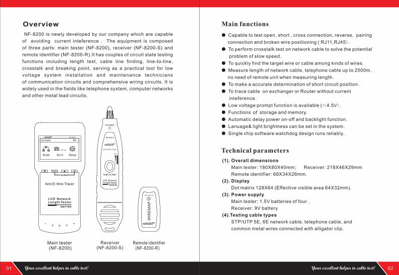
NF-8200 is capable
of avoiding current inteference . The equipment is composed
of three parts: main tester (NF-8200), receiver (NF-8200-S) and
remote identifier (NF-8200-R).It has couples of circuit state testing
functions including length test, cable line finding, line-to-line,
crosstalk and breaking point, serving as a practical tool for low
voltage system instal lat ion and maintenance technicians
of communication circuits and comprehensive wiring circuits. It is
widely used in the fields like telephone system, computer networks
and other metal lead circuits.
newly developed by our company which are
POWER
VOL
Remote identifier (NF-8200-R)
Main tester (NF-8200)
Receiver (NF-8200-S)
PUSH TO TEST
NF-8200-S
LCD Network Length Tester
RECEIVER
Anti-EI Wire TracerW
IRE
MA
P
NF-8200-R
PAIR&L
NF-8200
NOYAFA
SetupRJ11RJ45
CALIBRATE
LCD Network Length Tester
EMITTER
Anti-EI Wire Tracer
02
●
connection and broken wire positioning ( RJ11,RJ45) .
● To perform crosstalk test on network cable to solve the potential
problem of slow speed.
● To quickly find the target wire or cable among kinds of wires.
● Measure length of network cable, telephone cable up to 2500m,
no need of remote unit when measuring length.
● To make a accurate determination of short circuit position .
● To trace cable on exchanger or Router without current
inteference.
● Low voltage prompt function is available (<4.5V) .
● Functions of storage and memory.
● Automatic delay power on-off and backlight function.
● Lanuage& light brightness can be set in the system.
● Single chip software watchdog design runs reliably.
Capable to test open, short , cross connection, reverse, pairing
Main functions
Overall dimensions
Main tester: 180X80X40mm; Receiver: 218X46X29mm
Remote identifier: 68X34X26mm.
Display
Dot matrix 128X64 (Effective visible area 64X32mm).
(1).
(2).
(3). Power supply
Main tester: 1.5V batteries of four .
Receiver: 9V battery.
(4).Testing cable types
STP/UTP 5E, 6E network cable, telephone cable, and
common metal wires connected with alligator clip.
Technical parameters
Your excellent helper in cable test! Your excellent helper in cable test!
03
(5).Detecting cable types
STP/UTP 5E, 6E network cable, telephone cable,and common
metal wires connected with alligator clip. (6).Operating environment temperature/humidity
-10 ~ +60 /20% ~ 70%;℃ ℃
(7).Testing device interface
Main unit: RJ45 (M), RJ45 (S)loop interface, RJ11main interface;
Remote identifier: RJ45, connector。RJ11
(8).Length measurement
Range: 1-2500m;
Calibration precision: 2% (+/-0.5m, or +/-1.5 feet); (calibration;
cable >10m) measurement precision: 3% ((+/-0.5m, or +/-1.5 feet);
(AMP, CAT5E, 6E cable material)
Display unit: meter, inch, yard.
(9).Length calibration, storage and data load
User can set a length value at a known length, store the value in
the system,which can be used for future choice. and the calibration
length should be over 10m.
(10). Line sequence and cable failure positioning
Open, short, reverse , cross, crosstalk, etc.
(12). Setup
Unit & brightness & Auto-power off time can be set in this menu.
(11). Language set
Users can choose English or Chinese for operation.
WIR
EM
AP
NF-8200-R
PAIR&L
NF-8200
NOYAFA
SetupRJ11RJ45
CALIBRATE
LCD Network Length Tester
EMITTER
Anti-EI Wire Tracer
POWER
VOL
PUSH TO TEST
NF-8200-S
LCD Network Length Tester
RECEIVER
Anti-EI Wire Tracer
Main tester (NF-8200) Receiver (NF-8200-S)
Remote identifier (NF-8200-R)
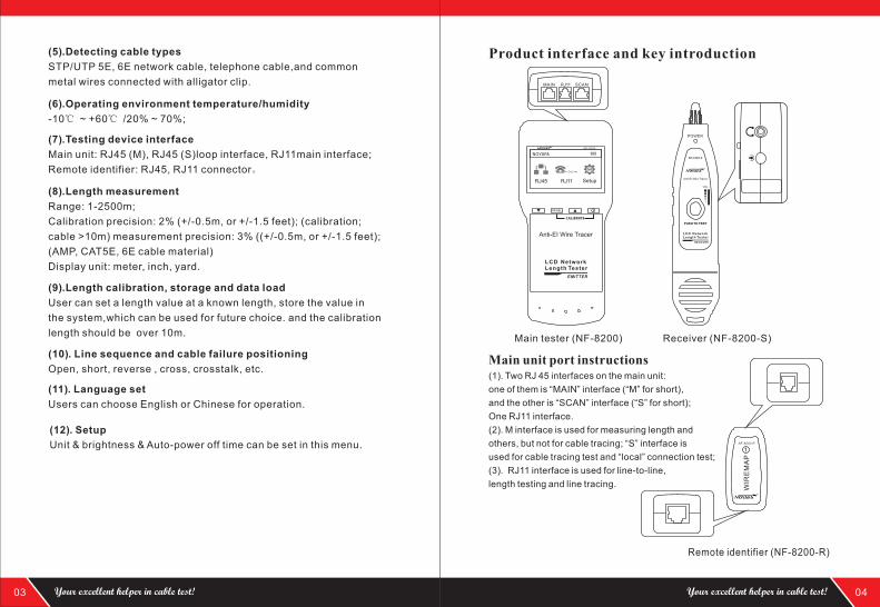
Product interface and key introduction
Main unit port instructions(1). Two RJ 45 interfaces on the main unit:
one of them is “MAIN” interface (“M” for short),
and the other is “SCAN” interface (“S” for short);
One RJ11 interface.
(2). M interface is used for measuring length and
others, but not for cable tracing; “S” interface is
used for cable tracing test and “local” connection test;
(3). RJ11 interface is used for line-to-line,
length testing and line tracing.
04
MAIN RJ11 SCAN
Your excellent helper in cable test! Your excellent helper in cable test!
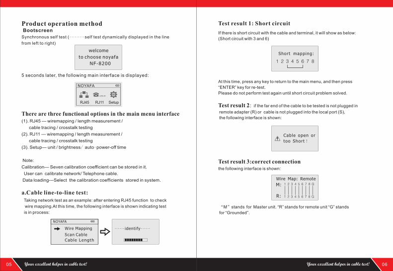
Product operation method
5 seconds later, the following main interface is displayed:
Bootscreen
Synchronous self test ( self test dynamically displayed in the line
from left to right)
------
05
welcome
to choose noyafa
NF-8200
There are three functional options in the main menu interface(1)
(2)
(3)
Note:
Calibration— Seven calibration coefficient can be stored in it.
User can calibrate network/ Telephone cable.
Data loading---Select the calibration coefficients stored in system.
. RJ45 — wiremapping / length measurement /
cable tracing / crosstalk testing
. RJ11 — wiremapping / length measurement /
cable tracing / crosstalk testing
. Setup— unit / brightness/ auto-power-off time
---- identify----
Taking network test as an example: after entering RJ45 function to check
wire mapping.At this time, the following interface is shown indicating test
is in process:
a.Cable line-to-line test:
Scan Cable
Cable Length
Wire Mapping
NOYAFA
Test result 1: Short circuit
Short mapping:
1 2 3 4 5 6 7 8
Cable open or
too Short !
If there is short circuit with the cable and terminal, it will show as below:
(Short circuit with 3 and 6)
At this time, press any key to return to the main menu, and then press
“ENTER” key for re-test.
Please do not perform test again until short circuit problem solved.
Test result 2: if the far end of the cable to be tested is not plugged in
remote adapter (R) or cable is not plugged into the local port (S),
the following interface is shown:
Test result 3:correct connectionthe following interface is shown:
“M”stands for Master unit. “R” stands for remote unit “G” stands
for “Grounded”.
06
1 2 3 4 5 6 7 8 GM:
R: 1 2 3 4 5 6 7 8 G
Wire Map: Remote
NOYAFA
RJ45 RJ11 Setup
Your excellent helper in cable test! Your excellent helper in cable test!
07
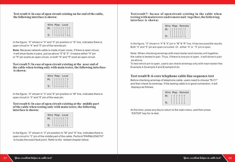
Note: Because network cable is made of pair cores, if there is open circuit,
it will show faults in pairs, just as above "4" &" 5". it means either "4" pin
or "5" pin exsits an open circuit, or both "4" and "5" exsit an open circuit.
Test result 5: In case of open circuit existing at the near end of the cable , the following interface is shown:
when testing only with main tester
In the figure, “X” shown in “3” and “6” pin position in “M” line, indicates there is
open circuit in “3” and “6” pin of the near pin.
Test result 6: In case of open circuit existing at the middle part of the cable , the following interface is shown:
when testing only with main tester
In the figure, “X” shown in “3” pin position in “M” and “S” line, indicates there is
open circuit in “3” pin of the middle part of the cable. Perform"PAIR&LENGTH"
to locate the exact fault point. Refer to the related chapter below.
1 2 X 4 5 X 7 8M:
S: 1 2 3 4 5 6 7 8
Wire Map: Local
1 2 X 4 5 6 7 8M:
S: 1 2 X 4 5 6 7 8
Wire Map: Local
Test result 4: In case of open circuit existing on far end of the cable, the following interface is shown:
In the figure, “X” shown in “4” and “5” pin position in “S” line, indicates there is
open circuit in “4” and “5” pin of the remote pin.
1 2 3 4 5 6 7 8 GM:
S: 1 2 3 X X 6 7 8 G
Wire Map: Local
08
Test result 7: In case of open circuit existing in the cable when testing with main tester and remote unit together, the following interface is shown:
In the figure, “X” shown in “4” & “5” pin in “M” & “R” line, It has two possible results.
Both “4” and “5” pin are open curcuited. Or , either “4” or “5” pin is open.
1 2 3 X X 6 7 8M:
R: 1 2 3 X X 6 7 8
Wire Map: Remote
Test result 8: 6-core telephone cable line sequence test
At this time, press any key to return to the main menu, and then press
“ENTER” key for re-test.
Before checking wiremap of telephone cable, users need to choose "RJ11"
and then check its wiremap. If the testing cable is in good connection, it will
displays as follows:
Wire Map: Remote1 2 3 4 5 6M:
R: 1 2 3 4 5 6
Note: When checking wiremap with main tester and remote unit together,
the cable is tested in pair. Thus, if there is one pin is open , it will show in pair
as above.
To test which pin is open, users can check wiremap only with main tester like
Example 4,Example 5 and Example 6 do.
Your excellent helper in cable test! Your excellent helper in cable test!
09
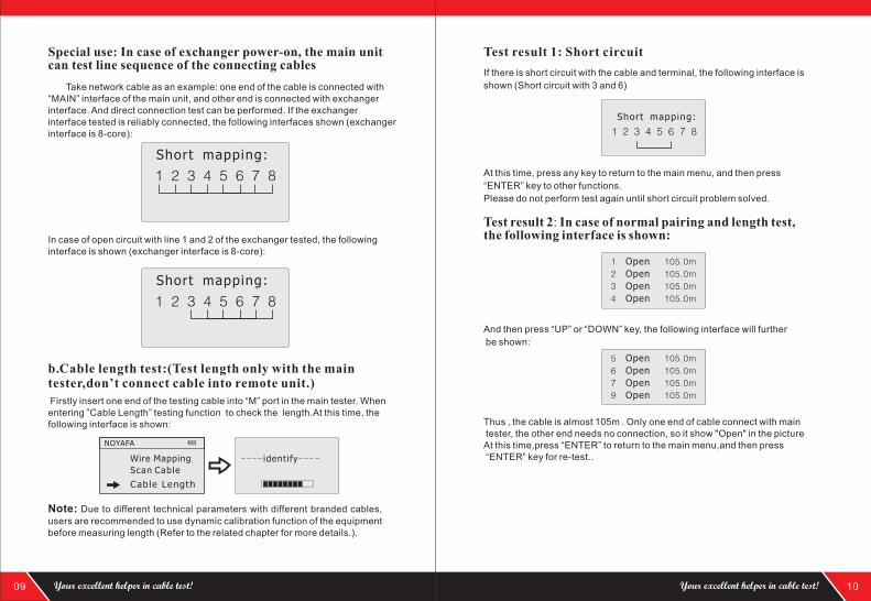
Special use: can test line sequence of the connecting cables
In case of exchanger power-on, the main unit
Take network cable as an example: one end of the cable is connected with “MAIN” interface of the main unit, and other end is connected with exchanger interface. And direct connection test can be performed. If the exchanger interface tested is reliably connected, the following interfaces shown (exchanger interface is 8-core):
In case of open circuit with line 1 and 2 of the exchanger tested, the following interface is shown (exchanger interface is 8-core):
1 2 3 4 5 6 7 8
Short mapping:
1 2 3 4 5 6 7 8
Short mapping:
b.Cable length test:(Test length only with the main tester,don’t connect cable into remote unit.)
Firstly insert one end of the testing cable into “M” port in the main tester. When entering ”Cable Length” testing function to check the length.At this time, the following interface is shown:
Note: Due to different technical parameters with different branded cables,
users are recommended to use dynamic calibration function of the equipment before measuring length (Refer to the related chapter for more details.).
---- identify----
Scan Cable
Cable Length
Wire Mapping
NOYAFA
10
Test result 1: Short circuit
If there is short circuit with the cable and terminal, the following interface is
shown (Short circuit with 3 and 6)
At this time, press any key to return to the main menu, and then press
“ENTER” key to other functions.
Please do not perform test again until short circuit problem solved.
Short mapping:
1 2 3 4 5 6 7 8
1 Open 105.0m
4 Open 105.0m
2 Open 105.0m
3 Open 105.0m
Test result 2: In case of normal pairing and length test, the following interface is shown:
And then press “UP” or “DOWN” key, the following interface will further
be shown:
5 Open 105.0m
9 Open 105.0m
6 Open 105.0m
7 Open 105.0m
Thus , the cable is almost 105m . Only one end of cable connect with main tester, the other end needs no connection, so it show "Open" in the picture
.At this time,press “ENTER” to return to the main menu,and then press “ENTER” key for re-test.
Your excellent helper in cable test! Your excellent helper in cable test!
11
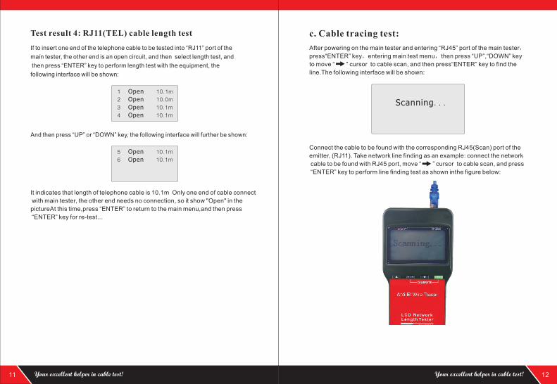
1 Open 1 0.1m
4 Open 1 10. m
2 Open 1 0 0. m
3 Open 1 10. m
5 Open 1 0.1m
6 Open 1 0.1m
Test result 4: RJ11(TEL) cable length test
And then press “UP” or “DOWN” key, the following interface will further be shown:
It indicates that length of telephone cable is 10.1m
.
Only one end of cable connect
with main tester, the other end needs no connection, so it show "Open" in the
pictureAt this time,press “ENTER” to return to the main menu,and then press
“ENTER” key for re-test..
If to insert one end of the cable to be tested into “ ” port of the
main tester, the other end is an open circuit, and then select length test, and
then press “ENTER” key to perform length test with the equipment, the
following interface will be shown:
telephone RJ11
12
Scanning...
c. Cable tracing test:
After powering on the main tester and entering
then press “UP”,“DOWN” key
to move “ ” cursor to cable scan, and then press“ENTER” key to find the
line.The following interface will be shown:
“RJ45” port of the main tester,
press“ENTER” key,entering main test menu,
Connect the cable to be found with the corresponding RJ45(Scan) port
, (RJ11). Take network line finding as an example: connect the network
cable to be found with RJ45 port, move “ ” cursor to cable scan, and press
“ENTER” key to perform line finding test as shown inthe figure below:
of the
emitter
Your excellent helper in cable test! Your excellent helper in cable test!
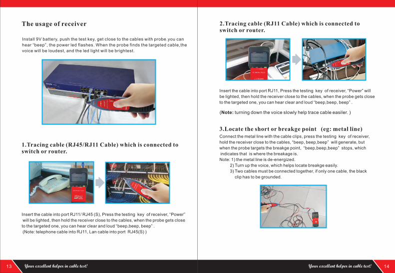
1.Tracing cable (RJ45/RJ11 Cable) which is connected to switch or router.
Insert the cable into port RJ11/ RJ45 (S), Press the testing key of receiver, “Power”
will be lighted, then hold the receiver close to the cables, when the probe gets close
to the targeted one, you can hear clear and loud “beep,beep, beep” .
(Note: telephone cable into RJ11, Lan cable into port RJ45(S) )
The usage of receiver
Install 9V battery, push the test key, get close to the cables with probe.you can
hear “beep”, the power led flashes. When the probe finds the targeted cable,the
voice will be loudest, and the led light will be brightest.
13 14Your excellent helper in cable test! Your excellent helper in cable test!
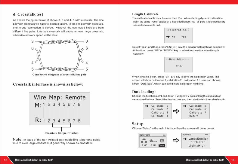
2.
Tracing cable (RJ11 Cable) which is connected to switch or router.
Insert the cable into port RJ11, Press the testing key of receiver, “Power” will
be lighted, then hold the receiver close to the cables, when the probe gets close
to the targeted one, you can hear clear and loud “beep,beep, beep” .
3.Locate the short or breakge point (eg: metal line)Connect the metal line with the cable clips, press the testing key of receiver,
hold the receiver close to the cables, “beep, beep,beep” will generate, but
when the probe targets the breakge point, “beep,beep,beep” stops, which
indicates that is where the breakage is.
Note: 1) the metal line is de-energized.
2) Turn up the voice, which helps locate breakge easily.
3) Two cables must be connected together, if only one cable, the black
clip has to be grounded.
(Note: turning down the voice slowly help trace cable easiler. )
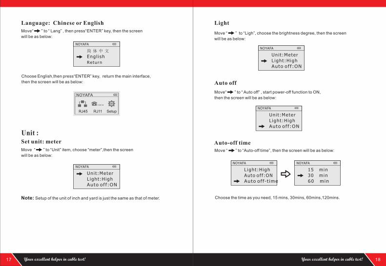
d. Crosstalk test
As shown the figure below: it shows 3, 6 and 4, 5 with crosstalk. The line
pair with crosstalk will flash to indicate failure. In the line pair with crosstalk,
end-to-end connection is correct. However the connected lines are from
different line pairs. Line pair crosstalk will cause an over large crosstalk,
otherwise network speed will be slow.
Crosstalk interface is shown as below:
Note: In case of the non-twisted-pair cable like telephone cable, due to over large crosstalk, it generally shown as crosstalk.
15
M:
R:
1 2 3 4 5 6 7 8
1 2 3 4 5 6 7 8
Crosstalk line pair flashes
Wire Map: Remote
16
C a l i b r a t i o n ?
No Yes
12.5m
Length CalibrateThe calibrated cable must be more than 10m, When starting dynamic calibration,
insert the same type of cables at a specified length into “M” port. It is unnecessary
to insert into remote unit.
Select “Yes”, and then press “ENTER” key, the measured length will be shown:
At this time, press “UP” or “DOWN” key to adjust to show the actual length
as below:
- -Base Adjust- - -
When length is given, press “ENTER” key to save the calibration value. The
screen will show calibration 1, cabliration 2...calibration 7. Users can choose
it from “Data load”, which can avoid more calibration next time.
Data loading:Choose the functions of “Load data”, it will show 7 sets of length values which
were stored before. Select the desired one and then start to test the cable length.
Ca l ib ra te 1
Ca l ib ra te 2
Ca l ib ra te 3
Ca l ib ra te 4
Ca l ib ra te 5
Ca l ib ra te 6
Ca l ib ra te 7
Return
SetupChoose “Setup” in the main interface,then the screen will be as below:
Uni t :Meter
L ight :H igh
Lang:Eng l i sh
NOYAFANOYAFA
RJ45 RJ11 Setup
3
4
5
6
3
4
5
6
Connection diagram of crosstalk line pair
Your excellent helper in cable test! Your excellent helper in cable test!
17
Unit :
Move to “Unit” item, choose “meter”,
“ ” then the screen
will be as below:
Note: Setup of the unit of inch and yard is just the same as that of meter.
Choose English, return the main interface, then press“ENTER” key,
then the screen will be as below:
Set unit: meter
L ight :H igh
Auto o f f :ON
Un i t :Meter
NOYAFA
Language: Chinese or English
Eng l i sh
Return
简 体 中 文
NOYAFA
Move“ ” to “ Lang” , then press“ENTER” key, then the screen
will be as below:
NOYAFA
RJ45 RJ11 Setup
18
Move “ ” to “Ligh”, choose the brightness degree, then the screen
will be as below:
Move“ ” to “ Auto off” , start power-off function to ON,
then the screen will be as below:
Auto-off time
Choose the time as you need, 15 mins, 30mins, 60mins,120mins.
Light
Auto off
Move “ ” to “Auto-off time”, then the screen will be as below:
L ight :H igh
Auto o f f :ON
Un i t :Meter
NOYAFA
L ight :H igh
Auto o f f :ON
Un i t :Meter
NOYAFA
Auto o f f :ON
Auto o f f- t ime
L ight :H igh
NOYAFA
30 m in
60 m in
15 m in
NOYAFA
Your excellent helper in cable test! Your excellent helper in cable test!
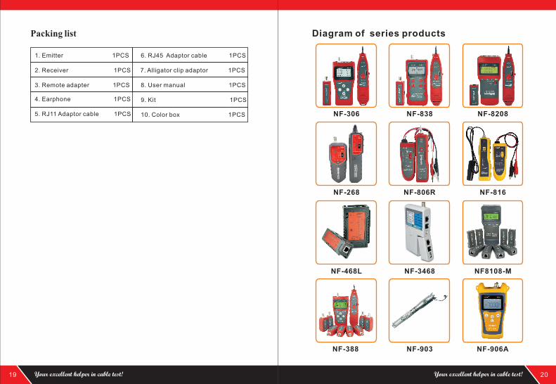
1. Emitter 1PCS
2. Receiver 1PCS
4. Earphone 1PCS
6. RJ45 Adaptor cable 1PCS
7. Alligator clip adaptor 1PCS
5. RJ11 Adaptor cable 1PCS
8. User manual 1PCS
9. Kit 1PCS
10. Color box 1PCS
3. Remote adapter 1PCS
Packing list
19 20
NF-388 NF-903 NF-906A
NF-268
NF-468L NF-3468 NF8108-M
NF-806R NF-816
NF-306 NF-838 NF-8208
Your excellent helper in cable test! Your excellent helper in cable test!


![Index [ ] · PDF fileCourse Length Tester Lea Strength Tester (Analog / Digital) CSP System Fabric Testing Instruments Busting ... 5 kg for ISO & 4.5kg for AATCC.? Size of acrylic](https://img.pdfslide.net/doc/110x75/5aa5bef97f8b9a517d8da544/index-length-tester-lea-strength-tester-analog-digital-csp-system-fabric.jpg)