Embed Size (px)
Citation preview

LCLS LCLS-II Survey & Alignment
International Review for PAL-XFEL Survey & Alignment
May 31, 2011
Catherine LeCocqSLAC Metrology Department
SLAC Site
3LCLS LCLS-II Survey & Alignment
Pohang Accelerator Laboratory, 05-31-2011
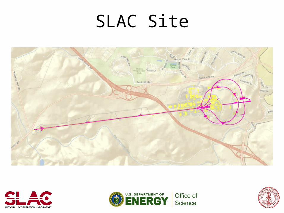
From John GalaydaLCLS-II DOE CD-1 ReviewApril 26, 2011
4
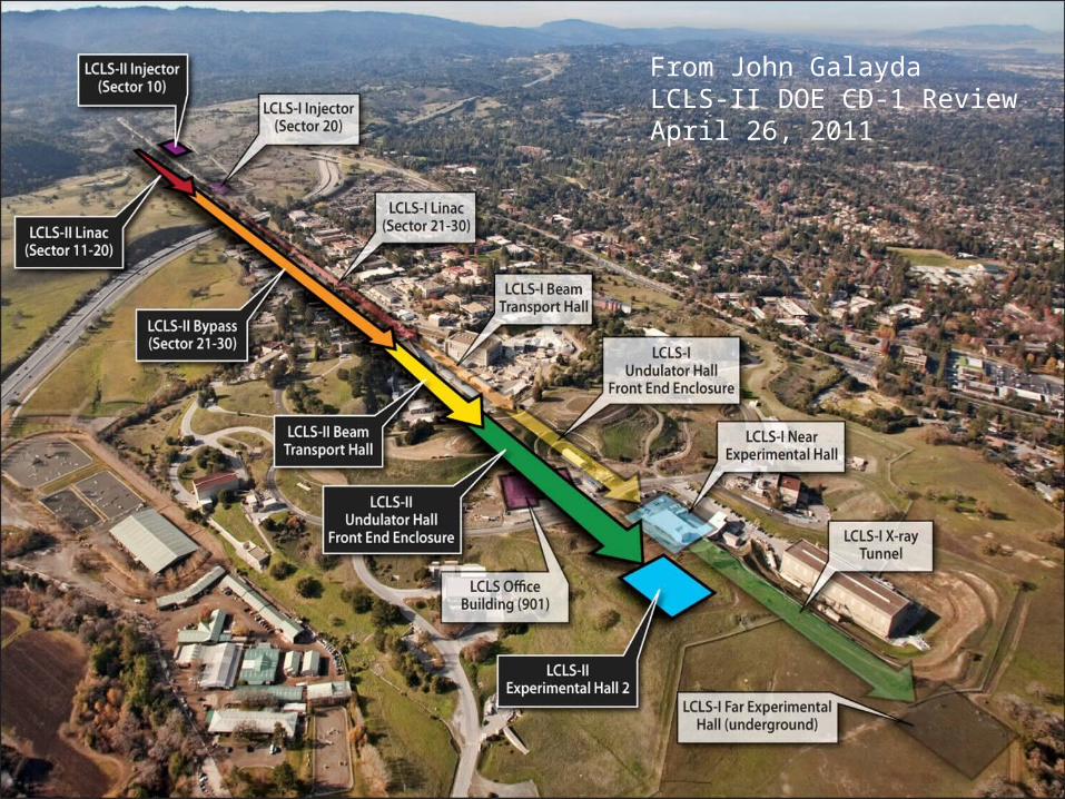
A Five Step Process
1. Planning• Information gathering
- Physics requirements- Engineering interfaces- Geodetic aspects
• Simulation2. Monument Network3. Component Fiducialization4. Installation
• Girder Alignment (if applicable)• Component Alignment• Mapping
5. Operation Phase• Monitoring (if applicable)• Mapping and re-alignment
LCLS LCLS-II Survey & AlignmentPohang Accelerator Laboratory, 05-31-2011
5
SLAC Instrumentation
• Primary Instrumentation:– Automatic Levels: Leica DNA03– Laser Trackers: FARO Xi (Leica AT401 to be acquired for LCLS-II)– In-house portable wire system
• Accessories: – Bar code rods: 2 meters and 0.6 meters long– Tripods: Brunson heavy stands, Kara portable tooling stands– Survey targets: 1 ½” Corner Cube Reflectors (12 per laser tracker)– Field Data Collectors: Paravant and Allegro
• Additional Equipment:– Total Stations: Leica TC2002 and TDA5005– FARO platinum portable arms (4ft, 8ft, 12ft)– Gyrotheodolites: GYROMAT 2000– Optical Plummet: Wild NL– GPS Receivers: Leica SR-530 – Laser Scanner: Z+F Imager 5006
LCLS LCLS-II Survey & AlignmentPohang Accelerator Laboratory, 05-31-2011
6
Software Model
LCLS LCLS-II Survey & AlignmentPohang Accelerator Laboratory, 05-31-2011
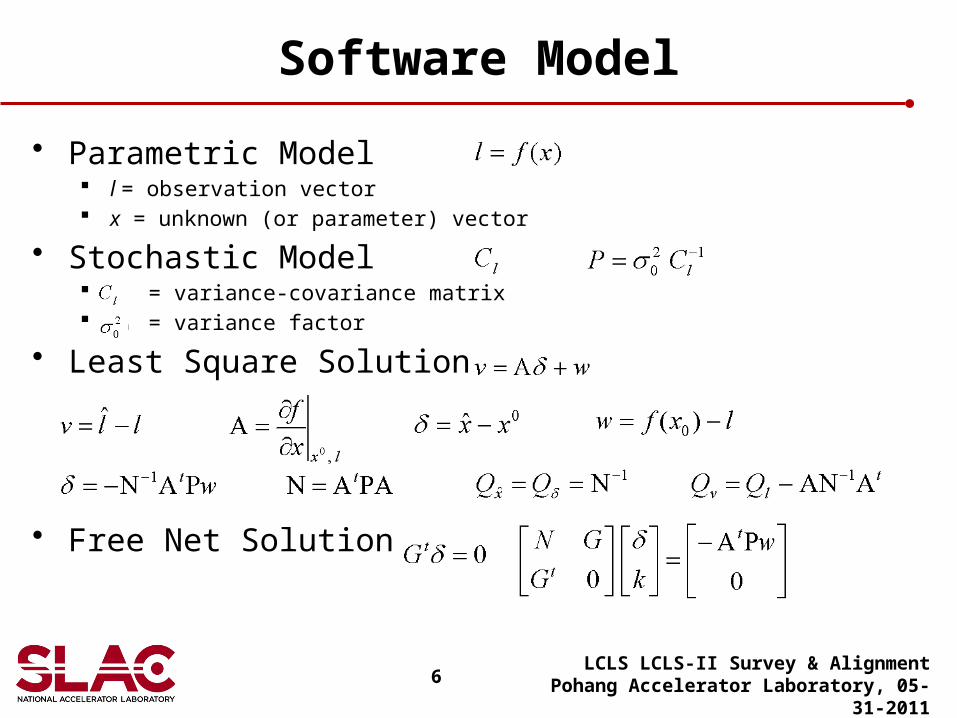
• Parametric Model l = observation vector x = unknown (or parameter) vector
• Stochastic Model = variance-covariance matrix = variance factor
• Least Square Solution
• Free Net Solution
7
LCLS-I UH Network Simulation
LCLS LCLS-II Survey & AlignmentPohang Accelerator Laboratory, 05-31-2011
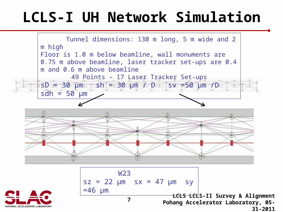
W23 sz = 22 μm sx = 47 μm sy =46 μm
Tunnel dimensions: 130 m long, 5 m wide and 2 m highFloor is 1.0 m below beamline, wall monuments are 0.75 m above beamline, laser tracker set-ups are 0.4 m and 0.6 m above beamline
49 Points – 17 Laser Tracker Set-upssD = 30 μm sh = 30 μm / D sv =50 μm /D sdh = 50 μm
8
LCLS-I Single Total Station Set-up
LCLS LCLS-II Survey & AlignmentPohang Accelerator Laboratory, 05-31-2011
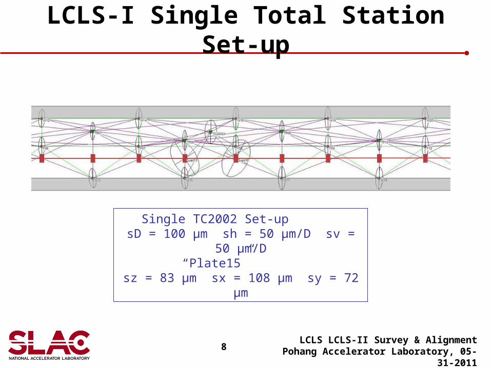
Single TC2002 Set-up sD = 100 μm sh = 50 μm/D sv = 50 μm/D
“Plate15” sz = 83 μm sx = 108 μm sy = 72 μm
9
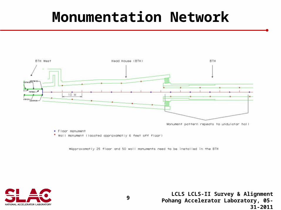
Monumentation Network
LCLS LCLS-II Survey & AlignmentPohang Accelerator Laboratory, 05-31-2011
10
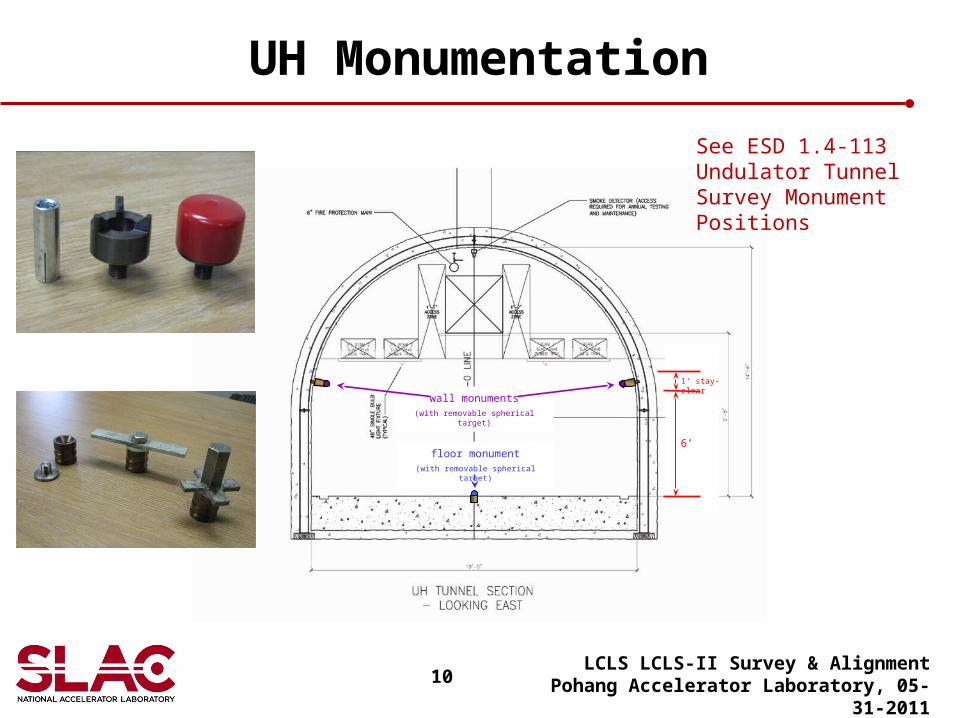
UH Monumentation
LCLS LCLS-II Survey & AlignmentPohang Accelerator Laboratory, 05-31-2011
wall monuments(with removable spherical target)
floor monument(with removable spherical target)
6’
1‘ stay-clear
See ESD 1.4-113 Undulator Tunnel Survey Monument Positions
11
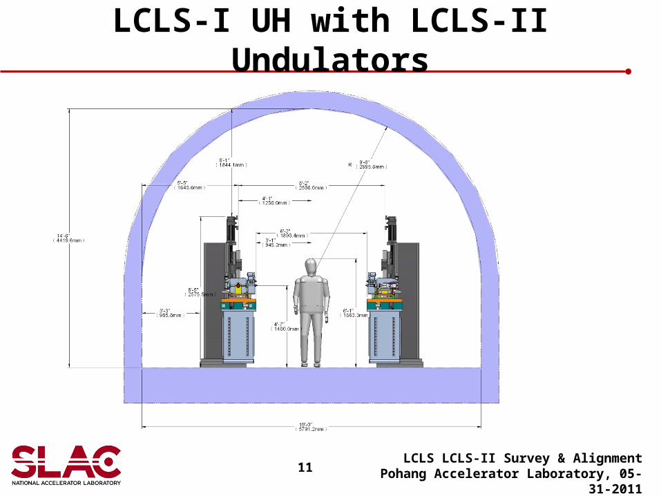
LCLS-I UH with LCLS-II Undulators
LCLS LCLS-II Survey & AlignmentPohang Accelerator Laboratory, 05-31-2011
12
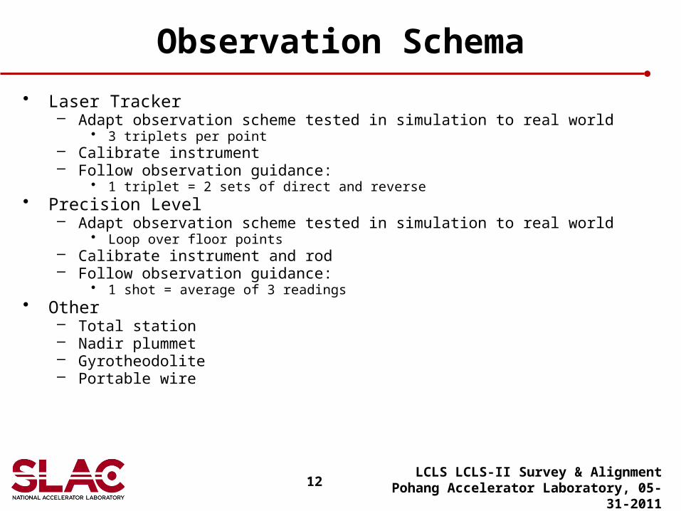
Observation Schema
• Laser Tracker– Adapt observation scheme tested in simulation to real world
• 3 triplets per point– Calibrate instrument– Follow observation guidance:
• 1 triplet = 2 sets of direct and reverse• Precision Level
– Adapt observation scheme tested in simulation to real world• Loop over floor points
– Calibrate instrument and rod– Follow observation guidance:
• 1 shot = average of 3 readings• Other
– Total station– Nadir plummet– Gyrotheodolite– Portable wire
LCLS LCLS-II Survey & AlignmentPohang Accelerator Laboratory, 05-31-2011
13
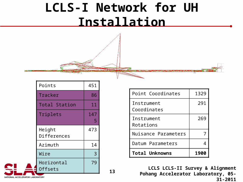
LCLS-I Network for UH Installation
LCLS LCLS-II Survey & AlignmentPohang Accelerator Laboratory, 05-31-2011
Points 451
Tracker 86
Total Station 11
Triplets 1475
Height Differences 473
Azimuth 14
Wire 3
Horizontal Offsets 79
Point Coordinates 1329
Instrument Coordinates 291
Instrument Rotations 269
Nuisance Parameters 7
Datum Parameters 4
Total Unknowns 1900
14
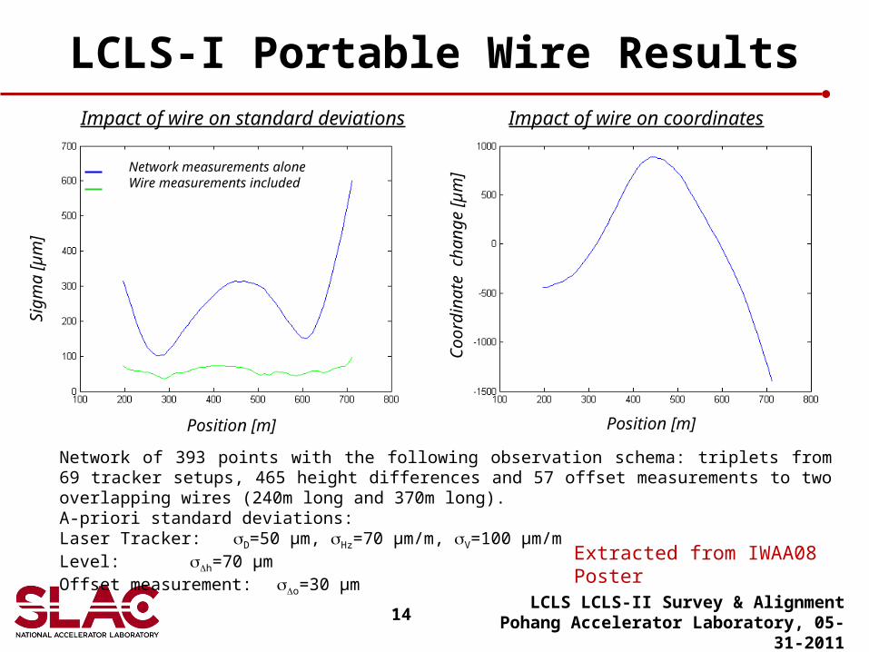
LCLS-I Portable Wire Results
LCLS LCLS-II Survey & AlignmentPohang Accelerator Laboratory, 05-31-2011
Position [m]
Sig
ma
[µm
]
Network measurements aloneWire measurements included
Position [m]
Coo
rdin
ate
ch
ange
[µ
m]
Impact of wire on standard deviations Impact of wire on coordinates
Network of 393 points with the following observation schema: triplets from 69 tracker setups, 465 height differences and 57 offset measurements to two overlapping wires (240m long and 370m long).A-priori standard deviations:Laser Tracker: sD=50 µm, sHz=70 µm/m, sV=100 µm/mLevel: sDh=70 µmOffset measurement: sDo=30 µm
Extracted from IWAA08 Poster
15
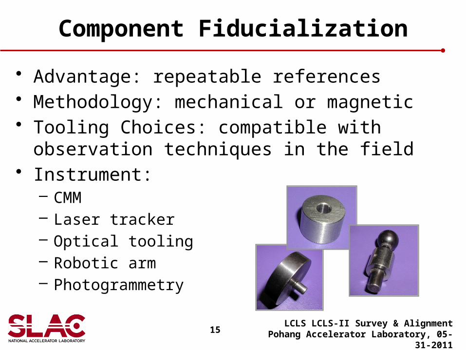
Component Fiducialization
• Advantage: repeatable references• Methodology: mechanical or magnetic• Tooling Choices: compatible with observation
techniques in the field• Instrument:
– CMM– Laser tracker– Optical tooling– Robotic arm– Photogrammetry
LCLS LCLS-II Survey & AlignmentPohang Accelerator Laboratory, 05-31-2011
16
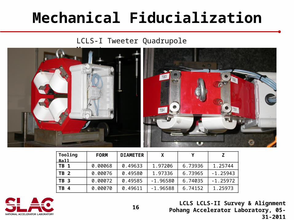
Mechanical Fiducialization
LCLS LCLS-II Survey & AlignmentPohang Accelerator Laboratory, 05-31-2011
LCLS-I Tweeter Quadrupole Magnet
Tooling Ball FORM DIAMETER X Y Z
TB 1 0.00068 0.49633 1.97206 6.73936 1.25744
TB 2 0.00076 0.49580 1.97336 6.73965 -1.25943
TB 3 0.00072 0.49585 -1.96580 6.74035 -1.25972
TB 4 0.00070 0.49611 -1.96588 6.74152 1.25973
17
Magnetic Fiducialization
LCLS LCLS-II Survey & AlignmentPohang Accelerator Laboratory, 05-31-2011
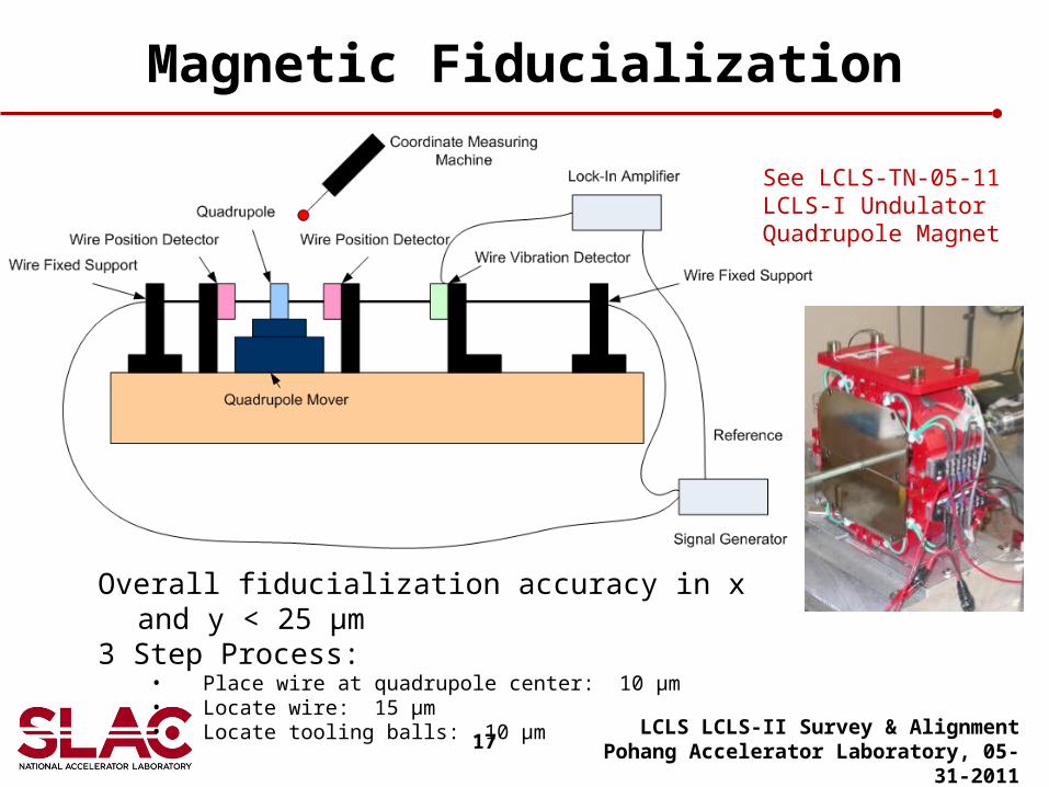
Overall fiducialization accuracy in x and y < 25 µm3 Step Process:
• Place wire at quadrupole center: 10 µm• Locate wire: 15 µm• Locate tooling balls: 10 µm
See LCLS-TN-05-11LCLS-I UndulatorQuadrupole Magnet
18
Undulator Fiducilization
LCLS LCLS-II Survey & AlignmentPohang Accelerator Laboratory, 05-31-2011
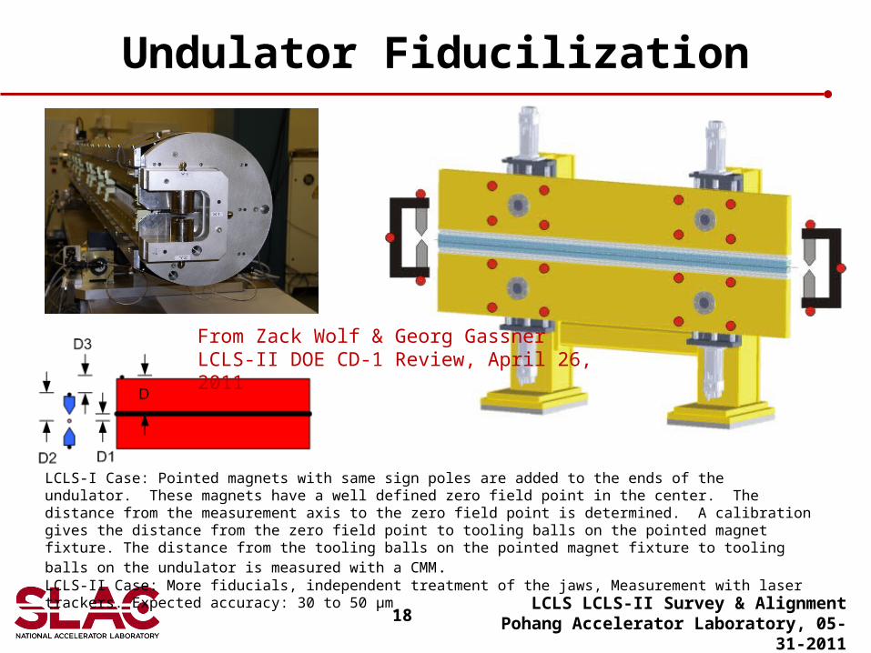
LCLS-I Case: Pointed magnets with same sign poles are added to the ends of the undulator. These magnets have a well defined zero field point in the center. The distance from the measurement axis to the zero field point is determined. A calibration gives the distance from the zero field point to tooling balls on the pointed magnet fixture. The distance from the tooling balls on the pointed magnet fixture to tooling balls on the undulator is measured with a CMM .LCLS-II Case: More fiducials, independent treatment of the jaws, Measurement with laser trackers. Expected accuracy: 30 to 50 μm
From Zack Wolf & Georg GassnerLCLS-II DOE CD-1 Review, April 26, 2011
19
Girder Alignment
• Advantages: – Better relative component alignment– Speed up installation phase
• Variations: – Individual component adjustment – Mover Mechanism:
• Fixed• Remote• Feedback
LCLS LCLS-II Survey & AlignmentPohang Accelerator Laboratory, 05-31-2011
20
LCLS-I Undulator Girder
LCLS LCLS-II Survey & AlignmentPohang Accelerator Laboratory, 05-31-2011
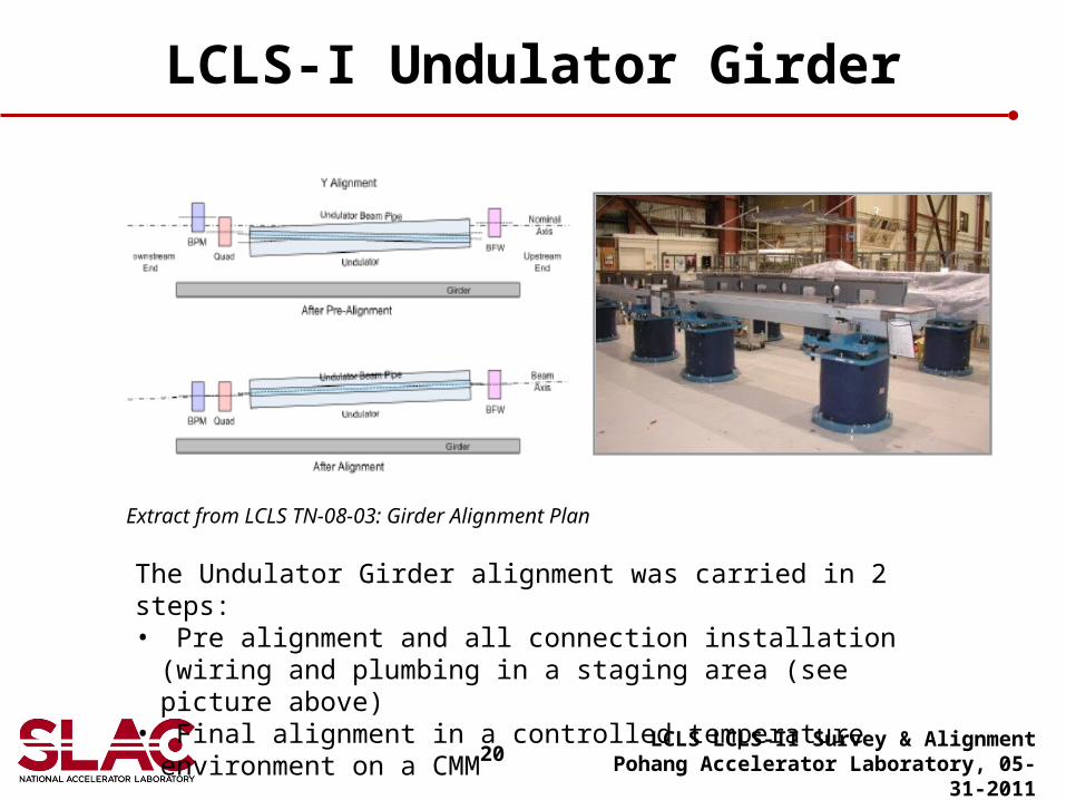
Extract from LCLS TN-08-03: Girder Alignment Plan
The Undulator Girder alignment was carried in 2 steps:• Pre alignment and all connection installation (wiring and plumbing
in a staging area (see picture above)• Final alignment in a controlled temperature environment on a CMM
21
LCLS Coordinate Measuring Machine
LCLS LCLS-II Survey & AlignmentPohang Accelerator Laboratory, 05-31-2011
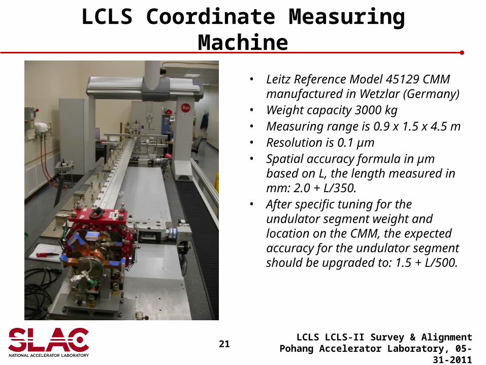
• Leitz Reference Model 45129 CMM manufactured in Wetzlar (Germany)
• Weight capacity 3000 kg • Measuring range is 0.9 x 1.5 x 4.5 m• Resolution is 0.1 µm• Spatial accuracy formula in µm
based on L, the length measured in mm: 2.0 + L/350.
• After specific tuning for the undulator segment weight and location on the CMM, the expected accuracy for the undulator segment should be upgraded to: 1.5 + L/500.
22
Component Alignment
• Timeline:– Template layout– Stand/base plate alignment– Component/girder alignment
• Principle: – Solid monument network– Component fiducialization– Local instrument set-ups
• Variations and possible difficulties come with the hardware installed:– Clearance around bolts– Mover system centered around their range– Component pre-set to nominal– Fiducial and mover in-line when possible– Right balance between fine and coarse thread
LCLS LCLS-II Survey & AlignmentPohang Accelerator Laboratory, 05-31-2011
23
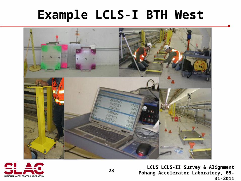
Example LCLS-I BTH West
LCLS LCLS-II Survey & AlignmentPohang Accelerator Laboratory, 05-31-2011
24
Mapping Phase
• Observation scheme:– Identical to monument network– Including component fiducials
• Computation phase:– Identical to monument network– Generating observed position and attitude (and their standard
deviations) for each component• Move list
– Option 1: to ideal– Option 2: to smooth line
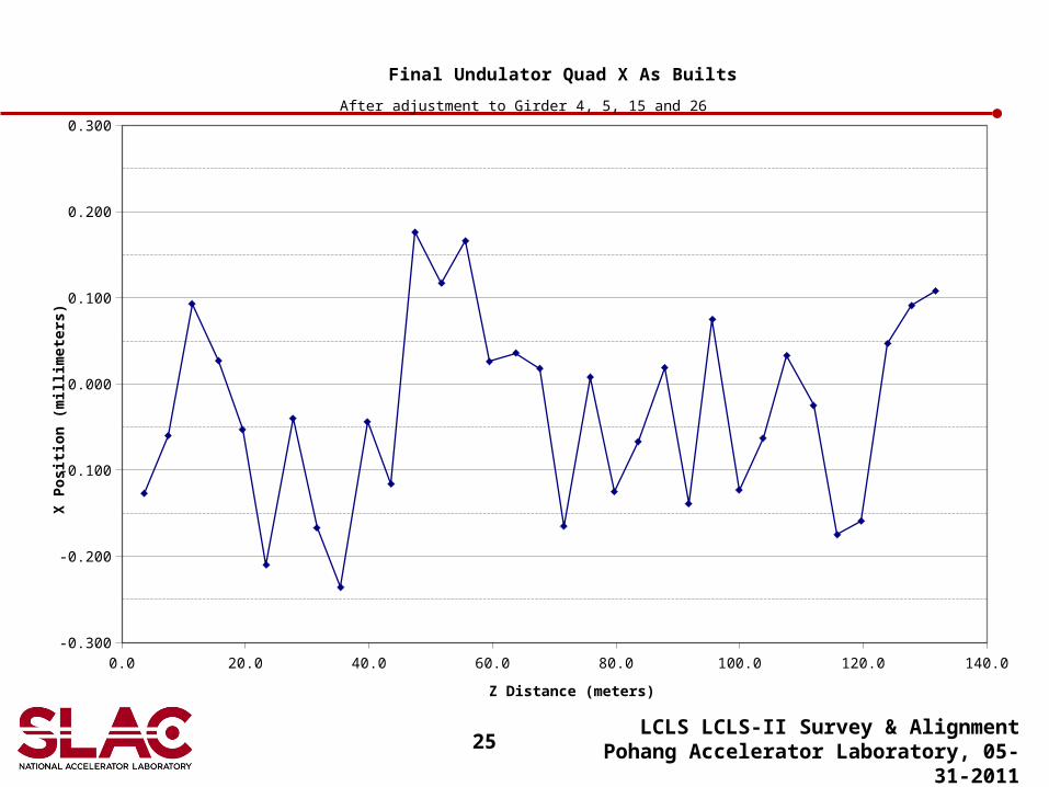
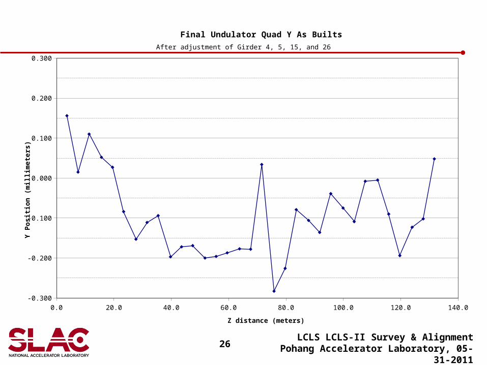
• The next 2 graphs show the as-built results for the 33 quadrupole magnets in the Undulator Hall in December 2008, right before the start of LCLS-I.
LCLS LCLS-II Survey & AlignmentPohang Accelerator Laboratory, 05-31-2011
25LCLS LCLS-II Survey & Alignment
Pohang Accelerator Laboratory, 05-31-2011
0.0 20.0 40.0 60.0 80.0 100.0 120.0 140.0-0.300
-0.200
-0.100
0.000
0.100
0.200
0.300
Final Undulator Quad X As Builts
Z Distance (meters)
X P
osi
tio
n (
mil
lim
eter
s)
After adjustment to Girder 4, 5, 15 and 26
26LCLS LCLS-II Survey & Alignment
Pohang Accelerator Laboratory, 05-31-2011
0.0 20.0 40.0 60.0 80.0 100.0 120.0 140.0-0.300
-0.200
-0.100
0.000
0.100
0.200
0.300
Final Undulator Quad Y As Builts
Z distance (meters)
Y P
osi
tio
n (
mil
lim
eter
s)
After adjustment of Girder 4, 5, 15, and 26
27
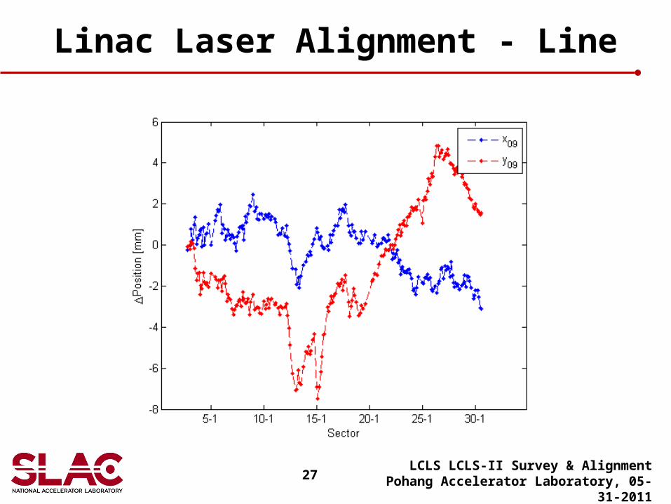
Linac Laser Alignment - Line
LCLS LCLS-II Survey & AlignmentPohang Accelerator Laboratory, 05-31-2011
28
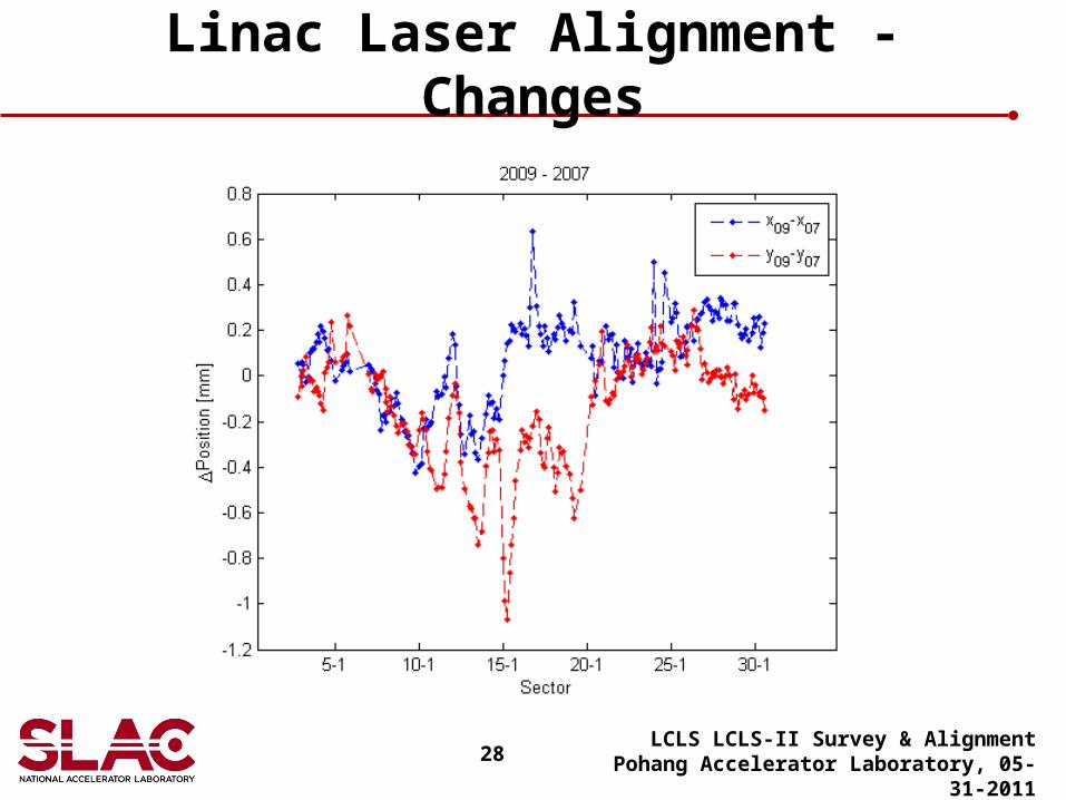
Linac Laser Alignment - Changes
LCLS LCLS-II Survey & AlignmentPohang Accelerator Laboratory, 05-31-2011
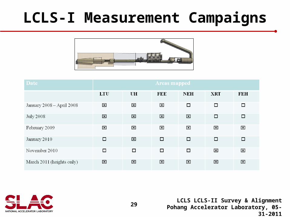
29
LCLS-I Measurement Campaigns
LCLS LCLS-II Survey & AlignmentPohang Accelerator Laboratory, 05-31-2011
30
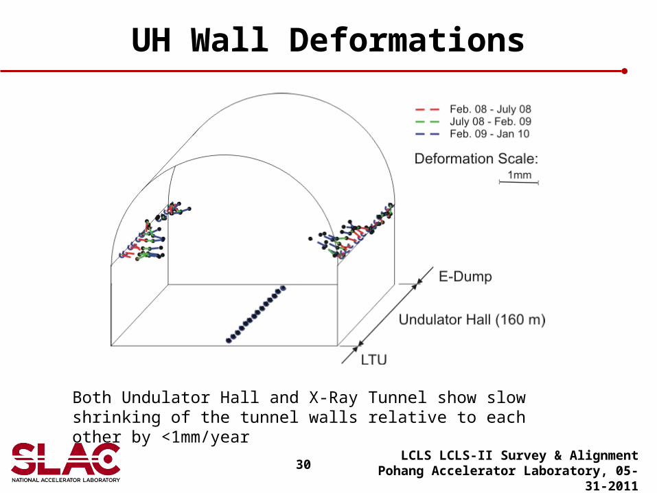
UH Wall Deformations
LCLS LCLS-II Survey & AlignmentPohang Accelerator Laboratory, 05-31-2011
Both Undulator Hall and X-Ray Tunnel show slow shrinking of the tunnel walls relative to each other by <1mm/year
31
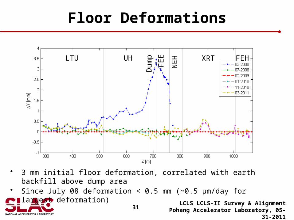
Floor Deformations
LCLS LCLS-II Survey & AlignmentPohang Accelerator Laboratory, 05-31-2011
• 3 mm initial floor deformation, correlated with earth backfill above dump area• Since July 08 deformation < 0.5 mm (~0.5 μm/day for largest deformation)
LTU UH
Dum
p
FE
E
NE
H XRT FEH
32
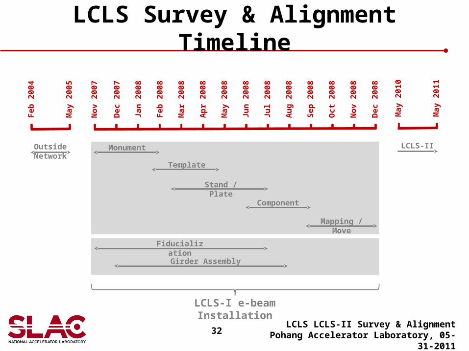
LCLS Survey & Alignment Timeline
LCLS LCLS-II Survey & AlignmentPohang Accelerator Laboratory, 05-31-2011
No
v 2
00
7
De
c 2
00
7
Ja
n 2
00
8
Fe
b 2
00
8
Ma
r 2
00
8
Ap
r 2
00
8
Ma
y 2
00
8
Ju
n 2
00
8
Ju
l 2
00
8
Au
g 2
00
8
Se
p 2
00
8
Oc
t 2
00
8
No
v 2
00
8
De
c 2
00
8
Monument
Template
Stand / Plate
Component
Mapping / Move
LCLS-I e-beam Installation
Fe
b 2
00
4
Ma
y 2
00
5
Outside Network
Fiducialization
Girder Assembly
Ma
y 2
01
0
Ma
y 2
011
LCLS-II