Embed Size (px)
Citation preview
LCP Ulna Osteotomy System 2.7. Low profile angular stable fixation for ulna shortening osteotomies.
Surgical Technique
This publication is not intended for distribution in the USA.
Instruments and implants approved by the AO Foundation.

LCP Ulna Osteotomy System 2.7 Surgical Technique DePuy Synthes 1
Table of Contents
Introduction LCP Ulna Osteotomy System 2.7 2
Indications 4
AO Principles 5
Surgical Technique Preoperative Planning 6
Preparation and Approach 7
Position and Fix Drill Template 8
A Transverse Osteotomy 10
B Oblique Osteotomy 18
Final Fixation of Locking Screws 30
Alternative Technique 31
Implant Removal 34
Product Information Implants 35
Instruments 36
MRI Information 40
Image intensifier control
This description alone does not provide sufficient background for direct use of DePuy Synthes products. Instruction by a surgeon experienced in handling these products is highly recommended.
Processing, Reprocessing, Care and MaintenanceFor general guidelines, function control and dismantling of multi-part instruments, as well as processing guidelines for implants, please contact your local sales representative or refer to:http://emea.depuysynthes.com/hcp/reprocessing-care-maintenanceFor general information about reprocessing, care and maintenance of Synthes reusable devices, instrument trays and cases, as well as processing of Synthes non-sterile implants, please consult the Important Information leaflet (SE_023827) or refer to: http://emea.depuysynthes.com/hcp/reprocessing-care-maintenance
2 DePuy Synthes LCP Ulna Osteotomy System 2.7 Surgical Technique
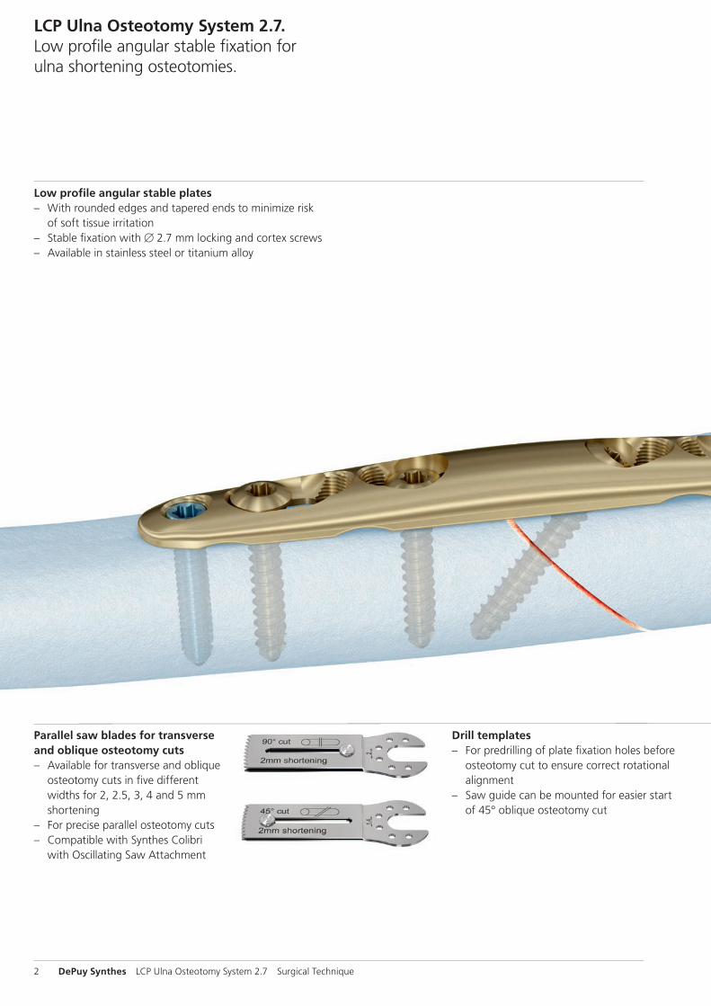
LCP Ulna Osteotomy System 2.7. Low profile angular stable fixation for ulna shortening osteotomies.
Low profile angular stable plates – With rounded edges and tapered ends to minimize risk
of soft tissue irritation – Stable fi xation with B 2.7 mm locking and cortex screws – Available in stainless steel or titanium alloy
Parallel saw blades for transverse and oblique osteotomy cuts – Available for transverse and oblique
osteotomy cuts in fi ve different widths for 2, 2.5, 3, 4 and 5 mm shortening
– For precise parallel osteotomy cuts – Compatible with Synthes Colibri
with Oscillating Saw Attachment
Drill templates – For predrilling of plate fi xation holes before
osteotomy cut to ensure correct rotational alignment
– Saw guide can be mounted for easier start of 45° oblique osteotomy cut
1
2
3
LCP Ulna Osteotomy System 2.7 Surgical Technique DePuy Synthes 3
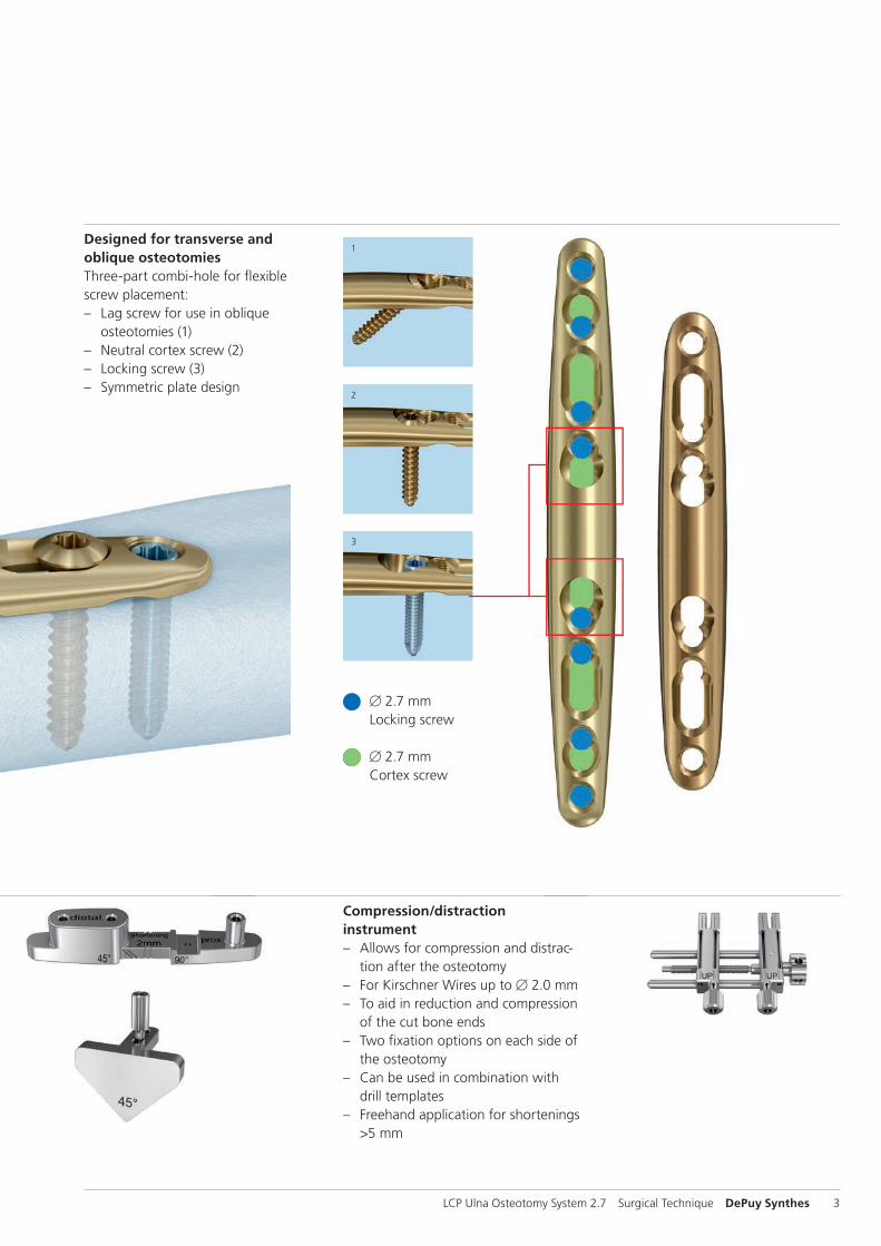
Designed for transverse and oblique osteotomiesThree-part combi-hole for fl exible screw placement: – Lag screw for use in oblique
osteotomies (1) – Neutral cortex screw (2) – Locking screw (3) – Symmetric plate design
Compression/distraction instrument – Allows for compression and distrac-
tion after the osteotomy – For Kirschner Wires up to B 2.0 mm – To aid in reduction and compression
of the cut bone ends – Two fi xation options on each side of
the osteotomy – Can be used in combination with
drill templates – Freehand application for shortenings
>5 mm
B 2.7 mmLocking screw
B 2.7 mmCortex screw

4 DePuy Synthes LCP Ulna Osteotomy System 2.7 Surgical Technique
Indications
Primary ulnar impaction syndrome – Degenerative triangular fibrocartilage complex (TFCC)
tears – Lunotriquetral tears
Secondary ulnar impaction syndrome – Incongruency (length discrepancy) of the distal radial-
ulnar joint following distal radius fracture – Traumatic triangular fibrocartilage complex (TFCC) tears
1
4
2
3
4_Priciples_03.pdf 1 05.07.12 12:08
4 DePuy Synthes Expert Lateral Femoral Nail Surgical Technique
AO PRINCIPLES
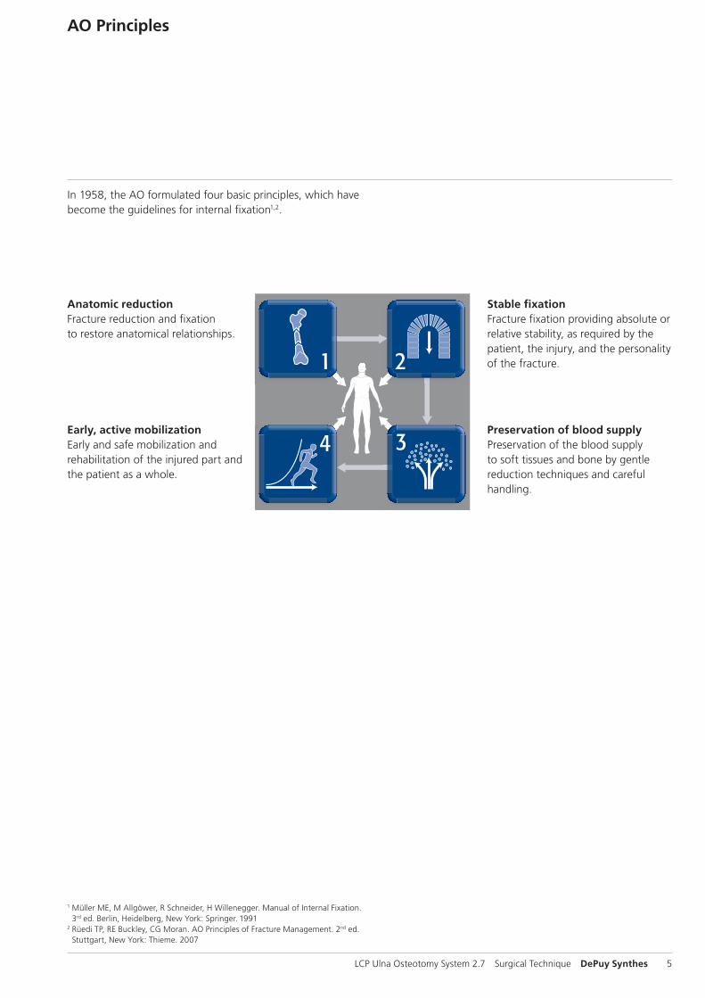
In 1958, the AO formulated four basic principles, which have become the guidelines for internal fixation1, 2.
1 Müller ME, M Allgöwer, R Schneider, H Willenegger. Manual of Internal Fixation. 3rd ed. Berlin Heidelberg New York: Springer. 1991.
2 Rüedi TP, RE Buckley, CG Moran. AO Principles of Fracture Management. 2nd ed. Stuttgart, New York: Thieme. 2007.
Anatomic reductionFracture reduction and fixation to restore anatomical relationships.
Early, active mobilizationEarly and safe mobilization and rehabilitation of the injured part and the patient as a whole.
Stable fixationFracture fixation providing abso-lute or relative stability, as required by the patient, the injury, and the personality of the fracture.
Preservation of blood supplyPreservation of the blood supply to soft tissues and bone by gentle reduction techniques and careful handling.
LCP Ulna Osteotomy System 2.7 Surgical Technique DePuy Synthes 5
AO Principles
Stable fixationFracture fixation providing absolute or relative stability, as required by the patient, the injury, and the personality of the fracture.
Anatomic reductionFracture reduction and fixation to restore anatomical relationships.
Early, active mobilizationEarly and safe mobilization and rehabilitation of the injured part and the patient as a whole.
Preservation of blood supplyPreservation of the blood supply to soft tissues and bone by gentle reduction techniques and careful handling.
In 1958, the AO formulated four basic principles, which have become the guidelines for internal fixation1,2.
1 Müller ME, M Allgöwer, R Schneider, H Willenegger. Manual of Internal Fixation. 3rd ed. Berlin, Heidelberg, New York: Springer. 1991
2 Rüedi TP, RE Buckley, CG Moran. AO Principles of Fracture Management. 2nd ed. Stuttgart, New York: Thieme. 2007
034.
000.
658
AA
30
1001
27
© 0
2/20
10 S
ynth
es, I
nc.
or
its
affi
liate
s A
ll ri
gh
ts r
eser
ved
Sy
nth
es a
nd
LC
P ar
e tr
adem
arks
of
Syn
thes
, In
c. o
r it
s af
filia
tes
For use only with the Original AO System ofInstruments and Implants
Synthes GmbHEimattstrasse 3CH-4436 Oberdorfwww.synthes.com
LCP Ulna Osteotomy Plate 2.7
1.10 Magnification
Holes0X.111.900 60X.111.901 8
AP
Vie
wLa
tera
l Vie
w
Ö034.000.658_AA&ä
X=2: Stainless SteelX=4: Titanium Alloy (TAN)
0 10 20 30 40 50 60 70 80 90 100 mm
6 DePuy Synthes LCP Ulna Osteotomy System 2.7 Surgical Technique
Complete preoperative radiographic assessment and preoperative planning is essential, especially in cases of secondary impaction.
Contralateral x-rays allow determination of the necessary amount of shortening.
The LCP Ulna Osteotomy Plate 2.7 is intended to be placed on the volar flat surface of the ulna, just proximal to the pronator quadratus muscle. It is recommended to place the plate between the distal and the middle third of the ulnar shaft.
Alternative plate placement, i.e. on the dorsal aspect is also possible.
The plate may be contoured for proper placement on the bone. To preserve the strength of the plate, avoid repetitive bending.
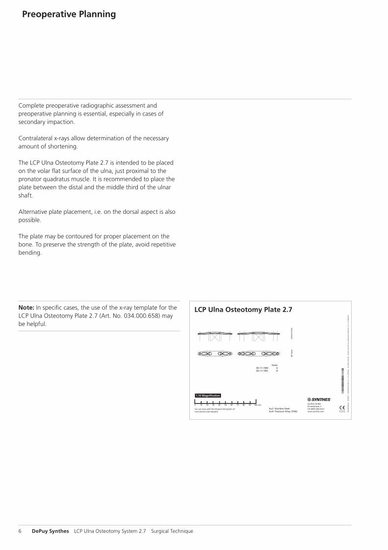
Note: In specific cases, the use of the x-ray template for the LCP Ulna Osteotomy Plate 2.7 (Art. No. 034.000.658) may be helpful.
Preoperative Planning
LCP Ulna Osteotomy System 2.7 Surgical Technique DePuy Synthes 7
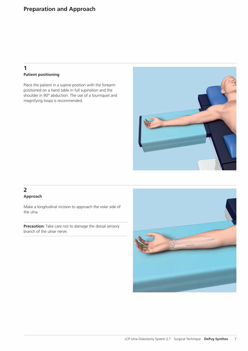
1Patient positioning
Place the patient in a supine position with the forearm positioned on a hand table in full supination and the shoulder in 90° abduction. The use of a tourniquet and magnifying loops is recommended.
Preparation and Approach
2Approach
Make a longitudinal incision to approach the volar side of the ulna.
Precaution: Take care not to damage the dorsal sensory branch of the ulnar nerve.
10 mm15 mm
3 21
8 DePuy Synthes LCP Ulna Osteotomy System 2.7 Surgical Technique
Position and Fix Drill Template
Instruments
03.111.900 Drill Template for LCP Ulna Osteotomy Plate 2.7, for 2.0 mm shortening
03.111.901 Drill Template for LCP Ulna Osteotomy Plate 2.7, for 2.5 mm shortening
03.111.902 Drill Template for LCP Ulna Osteotomy Plate 2.7, for 3.0 mm shortening
03.111.903 Drill Template for LCP Ulna Osteotomy Plate 2.7, for 4.0 mm shortening
03.111.904 Drill Template for LCP Ulna Osteotomy Plate 2.7, for 5.0 mm shortening
02.111.902.01 Kirschner Wire B 2.0 mm with drill tip, length 100 mm, Stainless Steel
02.111.903.01 Kirschner Wire B 2.0 mm with drill tip, length 150 mm, Stainless Steel
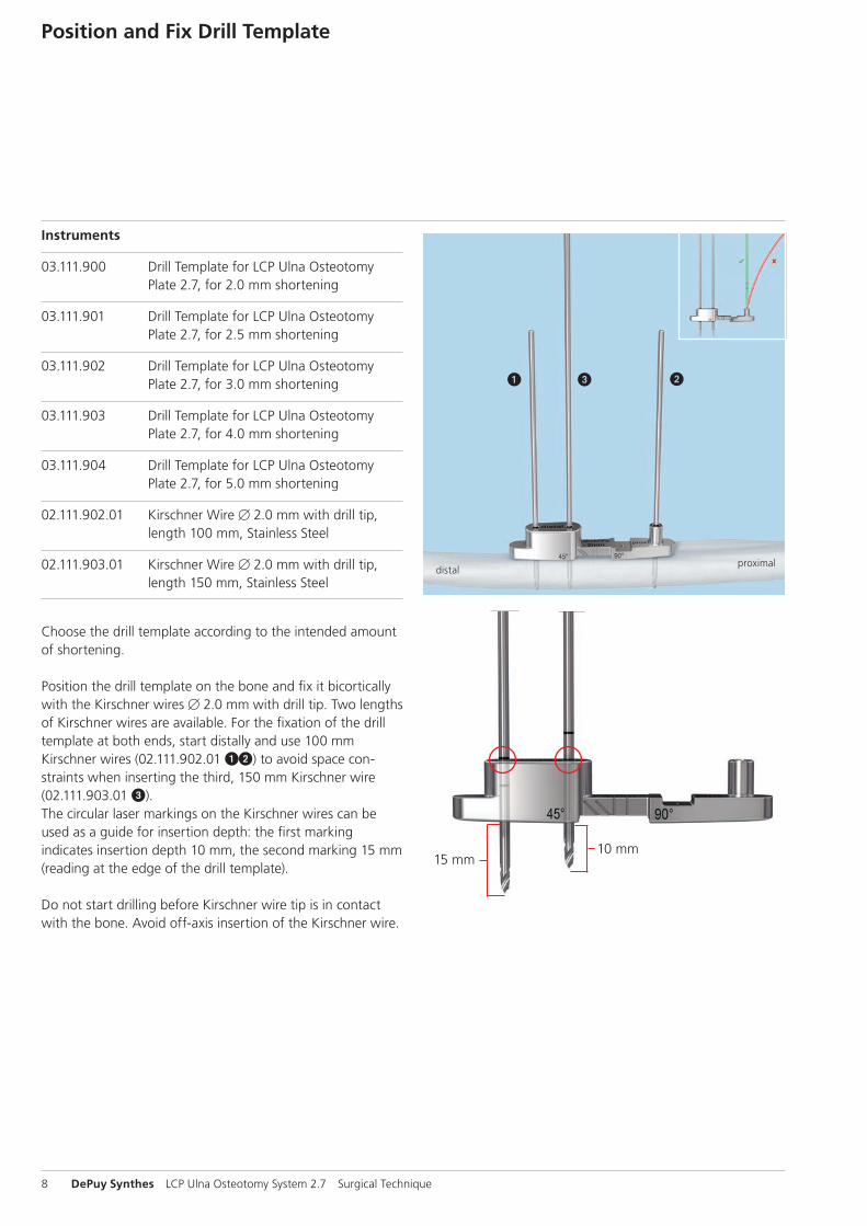
Choose the drill template according to the intended amount of shortening.
Position the drill template on the bone and fix it bicortically with the Kirschner wires B 2.0 mm with drill tip. Two lengths of Kirschner wires are available. For the fixation of the drill template at both ends, start distally and use 100 mm Kirschner wires (02.111.902.01 12) to avoid space con-straints when inserting the third, 150 mm Kirschner wire (02.111.903.01 3). The circular laser markings on the Kirschner wires can be used as a guide for insertion depth: the first marking indicates insertion depth 10 mm, the second marking 15 mm (reading at the edge of the drill template).
Do not start drilling before Kirschner wire tip is in contact with the bone. Avoid off-axis insertion of the Kirschner wire.
distalproximal
LCP Ulna Osteotomy System 2.7 Surgical Technique DePuy Synthes 9
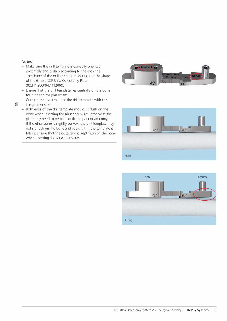
Notes: – Make sure the drill template is correctly oriented
proximally and distally according to the etchings. – The shape of the drill template is identical to the shape
of the 6-hole LCP Ulna Osteotomy Plate (02.111.900/04.111.900).
– Ensure that the drill template lies centrally on the bone for proper plate placement.
– Confirm the placement of the drill template with the image intensifier.
– Both ends of the drill template should sit flush on the bone when inserting the Kirschner wires; otherwise the plate may need to be bent to fit the patient anatomy.
– If the ulnar bone is slightly convex, the drill template may not sit flush on the bone and could tilt. If the template is tilting, ensure that the distal end is kept flush on the bone when inserting the Kirschner wires.
Flush
Tilting
distal proximal
1
2
3
10 DePuy Synthes LCP Ulna Osteotomy System 2.7 Surgical Technique
A Transverse Osteotomy
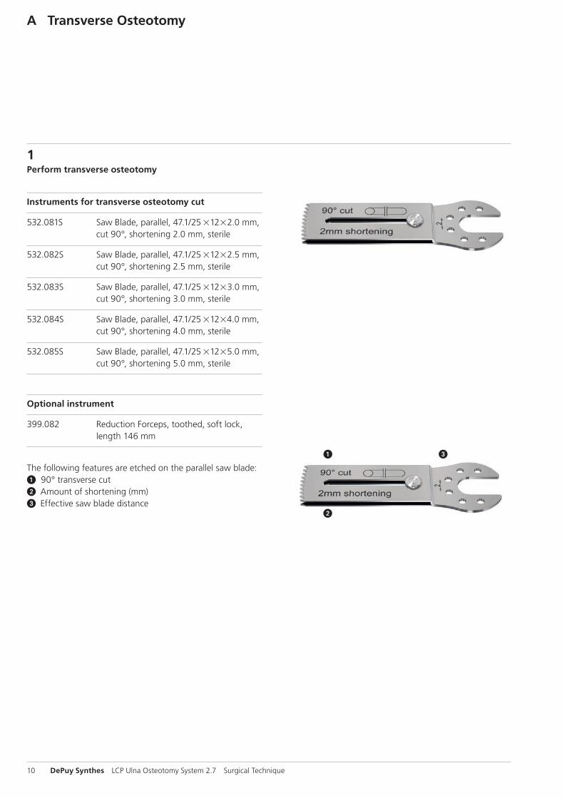
1Perform transverse osteotomy
Instruments for transverse osteotomy cut
532.081S Saw Blade, parallel, 47.1/2521222.0 mm, cut 90°, shortening 2.0 mm, sterile
532.082S Saw Blade, parallel, 47.1/2521222.5 mm, cut 90°, shortening 2.5 mm, sterile
532.083S Saw Blade, parallel, 47.1/2521223.0 mm, cut 90°, shortening 3.0 mm, sterile
532.084S Saw Blade, parallel, 47.1/2521224.0 mm, cut 90°, shortening 4.0 mm, sterile
532.085S Saw Blade, parallel, 47.1/2521225.0 mm, cut 90°, shortening 5.0 mm, sterile
Optional instrument
399.082 Reduction Forceps, toothed, soft lock, length 146 mm
The following features are etched on the parallel saw blade:1 90° transverse cut2 Amount of shortening (mm)3 Effective saw blade distance
LCP Ulna Osteotomy System 2.7 Surgical Technique DePuy Synthes 11
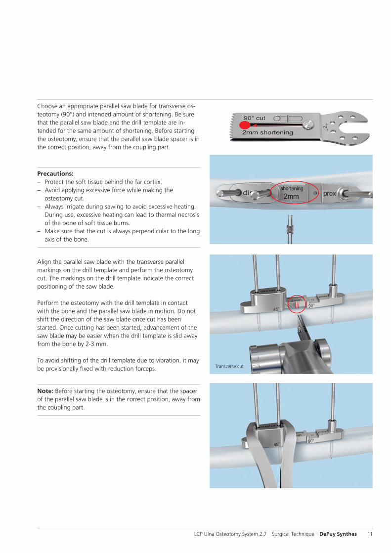
Choose an appropriate parallel saw blade for transverse os-teotomy (90°) and intended amount of shortening. Be sure that the parallel saw blade and the drill template are in-tended for the same amount of shortening. Before starting the osteotomy, ensure that the parallel saw blade spacer is in the correct position, away from the coupling part.
Precautions: – Protect the soft tissue behind the far cortex. – Avoid applying excessive force while making the
osteotomy cut. – Always irrigate during sawing to avoid excessive heating.
During use, excessive heating can lead to thermal necrosis of the bone of soft tissue burns.
– Make sure that the cut is always perpendicular to the long axis of the bone.
Align the parallel saw blade with the transverse parallel markings on the drill template and perform the osteotomy cut. The markings on the drill template indicate the correct positioning of the saw blade.
Perform the osteotomy with the drill template in contactwith the bone and the parallel saw blade in motion. Do not shift the direction of the saw blade once cut has been started. Once cutting has been started, advancement of the saw blade may be easier when the drill template is slid away from the bone by 2-3 mm.
To avoid shifting of the drill template due to vibration, it may be provisionally fixed with reduction forceps.
Note: Before starting the osteotomy, ensure that the spacer of the parallel saw blade is in the correct position, away from the coupling part.
Transverse cut
12 DePuy Synthes LCP Ulna Osteotomy System 2.7 Surgical Technique
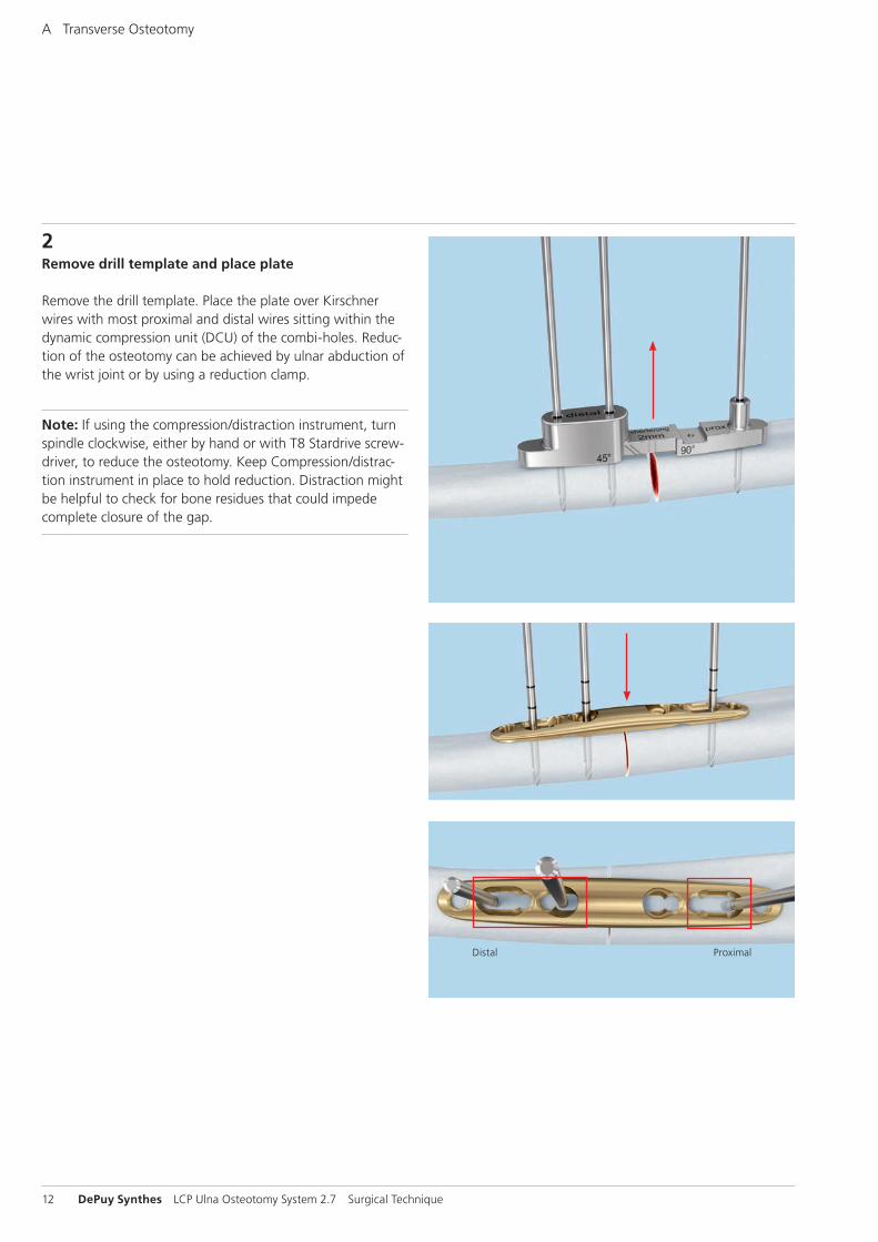
2Remove drill template and place plate
Remove the drill template. Place the plate over Kirschner wires with most proximal and distal wires sitting within the dynamic compression unit (DCU) of the combi-holes. Reduc-tion of the osteotomy can be achieved by ulnar abduction of the wrist joint or by using a reduction clamp.
Note: If using the compression/distraction instrument, turn spindle clockwise, either by hand or with T8 Stardrive screw-driver, to reduce the osteotomy. Keep Compression/distrac-tion instrument in place to hold reduction. Distraction might be helpful to check for bone residues that could impede complete closure of the gap.
A Transverse Osteotomy
Distal Proximal
LCP Ulna Osteotomy System 2.7 Surgical Technique DePuy Synthes 13
3Fix plate with cortex and locking screws
Note: – In young patients with dense cortical bone, screw inser-
tion might be difficult. To make screw insertion easier, the screw can be turned counterclockwise once or twice and reinserted again.
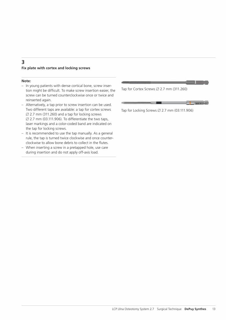
– Alternatively, a tap prior to screw insertion can be used. Two different taps are available: a tap for cortex screws B 2.7 mm (311.260) and a tap for locking screws B 2.7 mm (03.111.906). To differentiate the two taps, laser markings and a color-coded band are indicated on the tap for locking screws.
– It is recommended to use the tap manually. As a general rule, the tap is turned twice clockwise and once counter-clockwise to allow bone debris to collect in the flutes.
– When inserting a screw in a pretapped hole, use care during insertion and do not apply off-axis load.
Tap for Cortex Screws B 2.7 mm (311.260)
Tap for Locking Screws B 2.7 mm (03.111.906)
1
14 DePuy Synthes LCP Ulna Osteotomy System 2.7 Surgical Technique
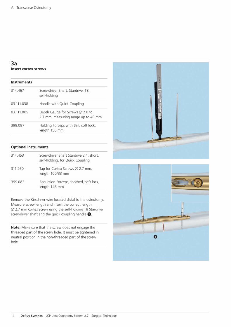
3aInsert cortex screws
Instruments
314.467 Screwdriver Shaft, Stardrive, T8, self-holding
03.111.038 Handle with Quick Coupling
03.111.005 Depth Gauge for Screws B 2.0 to 2.7 mm, measuring range up to 40 mm
399.087 Holding Forceps with Ball, soft lock, length 156 mm
Optional instruments
314.453 Screwdriver Shaft Stardrive 2.4, short, self-holding, for Quick Coupling
311.260 Tap for Cortex Screws B 2.7 mm, length 100/33 mm
399.082 Reduction Forceps, toothed, soft lock, length 146 mm
Remove the Kirschner wire located distal to the osteotomy. Measure screw length and insert the correct length B 2.7 mm cortex screw using the self-holding T8 Stardrive screwdriver shaft and the quick coupling handle 1.
Note: Make sure that the screw does not engage the threaded part of the screw hole. It must be tightened in neutral position in the non-threaded part of the screw hole.
A Transverse Osteotomy
2
4
1
3
2 1
2 13
LCP Ulna Osteotomy System 2.7 Surgical Technique DePuy Synthes 15
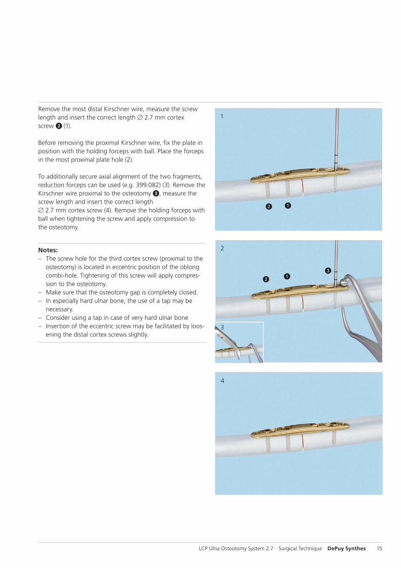
Remove the most distal Kirschner wire, measure the screw length and insert the correct length B 2.7 mm cortex screw 2 (1).
Before removing the proximal Kirschner wire, fix the plate in position with the holding forceps with ball. Place the forceps in the most proximal plate hole (2).
To additionally secure axial alignment of the two fragments, reduction forceps can be used (e.g. 399.082) (3). Remove the Kirschner wire proximal to the osteotomy 3, measure the screw length and insert the correct length B 2.7 mm cortex screw (4). Remove the holding forceps with ball when tightening the screw and apply compression to the osteotomy.
Notes: – The screw hole for the third cortex screw (proximal to the
osteotomy) is located in eccentric position of the oblong combi-hole. Tightening of this screw will apply compres-sion to the osteotomy.
– Make sure that the osteotomy gap is completely closed. – In especially hard ulnar bone, the use of a tap may be
necessary. – Consider using a tap in case of very hard ulnar bone – Insertion of the eccentric screw may be facilitated by loos-
ening the distal cortex screws slightly.

16 DePuy Synthes LCP Ulna Osteotomy System 2.7 Surgical Technique
3bInsert locking screws
Instruments
323.033 LCP Drill Sleeve for LCP Screws B 2.7 mm (head LCP 2.4), with Scale up to 30 mm, for Drill Bits B 2.0 mm
310.534 Drill Bit B 2.0 mm, with marking, length 110/85 mm, 2-flute, for Quick Coupling
03.111.005 Depth Gauge for Screws B 2.0 to 2.7 mm, measuring range up to 40 mm
314.467 Screwdriver Shaft, Stardrive, T8, self-holding
03.111.038 Handle with Quick Coupling
Optional instruments
03.111.906 Tap for Locking Screws B 2.7 mm, length 100/33 mm
314.453 Screwdriver Shaft Stardrive 2.4, short, self-holding, for Quick Coupling
Screw the LCP drill sleeve into the most distal locking hole until fully seated.
Use the B 2.0 mm drill bit to drill to the desired depth.
Measure the screw length either by using the scale on the drill bit or by using the depth gauge.
A Transverse Osteotomy
LCP Ulna Osteotomy System 2.7 Surgical Technique DePuy Synthes 17
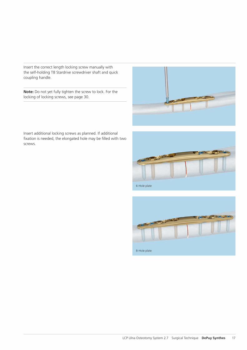
Insert the correct length locking screw manually with the self-holding T8 Stardrive screwdriver shaft and quick coupling handle.
Note: Do not yet fully tighten the screw to lock. For the locking of locking screws, see page 30.
Insert additional locking screws as planned. If additional fixation is needed, the elongated hole may be filled with two screws.
6-Hole plate
8-Hole plate
1
2
3
18 DePuy Synthes LCP Ulna Osteotomy System 2.7 Surgical Technique
B Oblique Osteotomy
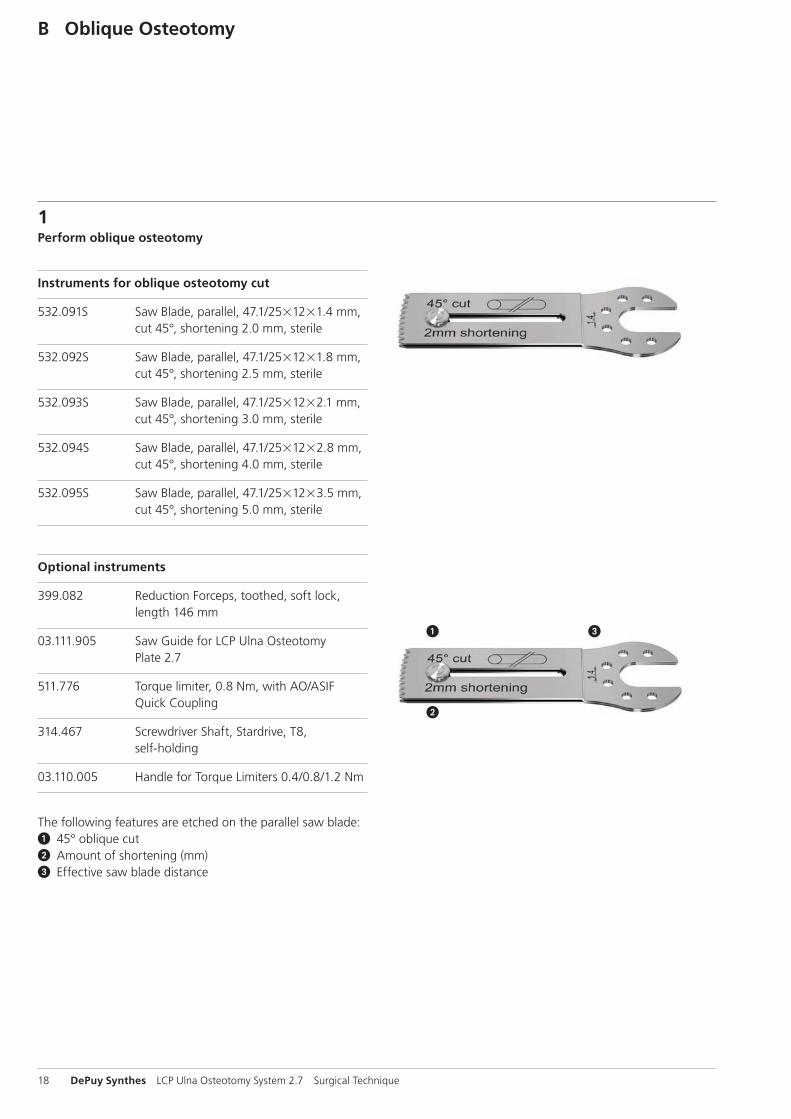
1Perform oblique osteotomy
Instruments for oblique osteotomy cut
532.091S Saw Blade, parallel, 47.1/2521221.4 mm, cut 45°, shortening 2.0 mm, sterile
532.092S Saw Blade, parallel, 47.1/2521221.8 mm, cut 45°, shortening 2.5 mm, sterile
532.093S Saw Blade, parallel, 47.1/2521222.1 mm, cut 45°, shortening 3.0 mm, sterile
532.094S Saw Blade, parallel, 47.1/2521222.8 mm, cut 45°, shortening 4.0 mm, sterile
532.095S Saw Blade, parallel, 47.1/2521223.5 mm, cut 45°, shortening 5.0 mm, sterile
Optional instruments
399.082 Reduction Forceps, toothed, soft lock, length 146 mm
03.111.905 Saw Guide for LCP Ulna Osteotomy Plate 2.7
511.776 Torque limiter, 0.8 Nm, with AO/ASIF Quick Coupling
314.467 Screwdriver Shaft, Stardrive, T8, self-holding
03.110.005 Handle for Torque Limiters 0.4/0.8/1.2 Nm
The following features are etched on the parallel saw blade:1 45° oblique cut2 Amount of shortening (mm)3 Effective saw blade distance
1 2
LCP Ulna Osteotomy System 2.7 Surgical Technique DePuy Synthes 19
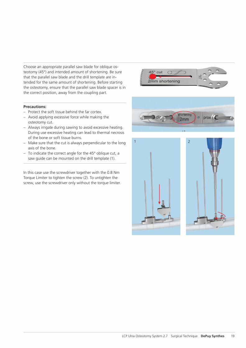
Choose an appropriate parallel saw blade for oblique os-teotomy (45°) and intended amount of shortening. Be sure that the parallel saw blade and the drill template are in-tended for the same amount of shortening. Before starting the osteotomy, ensure that the parallel saw blade spacer is in the correct position, away from the coupling part.
Precautions: – Protect the soft tissue behind the far cortex. – Avoid applying excessive force while making the
osteotomy cut. – Always irrigate during sawing to avoid excessive heating.
During use excessive heating can lead to thermal necrosis of the bone or soft tissue burns.
– Make sure that the cut is always perpendicular to the long axis of the bone.
– To indicate the correct angle for the 45° oblique cut, a saw guide can be mounted on the drill template (1).
In this case use the screwdriver together with the 0.8 Nm Torque Limiter to tighten the screw (2). To untighten the screw, use the screwdriver only without the torque limiter.
3
4
20 DePuy Synthes LCP Ulna Osteotomy System 2.7 Surgical Technique
B Oblique Osteotomy
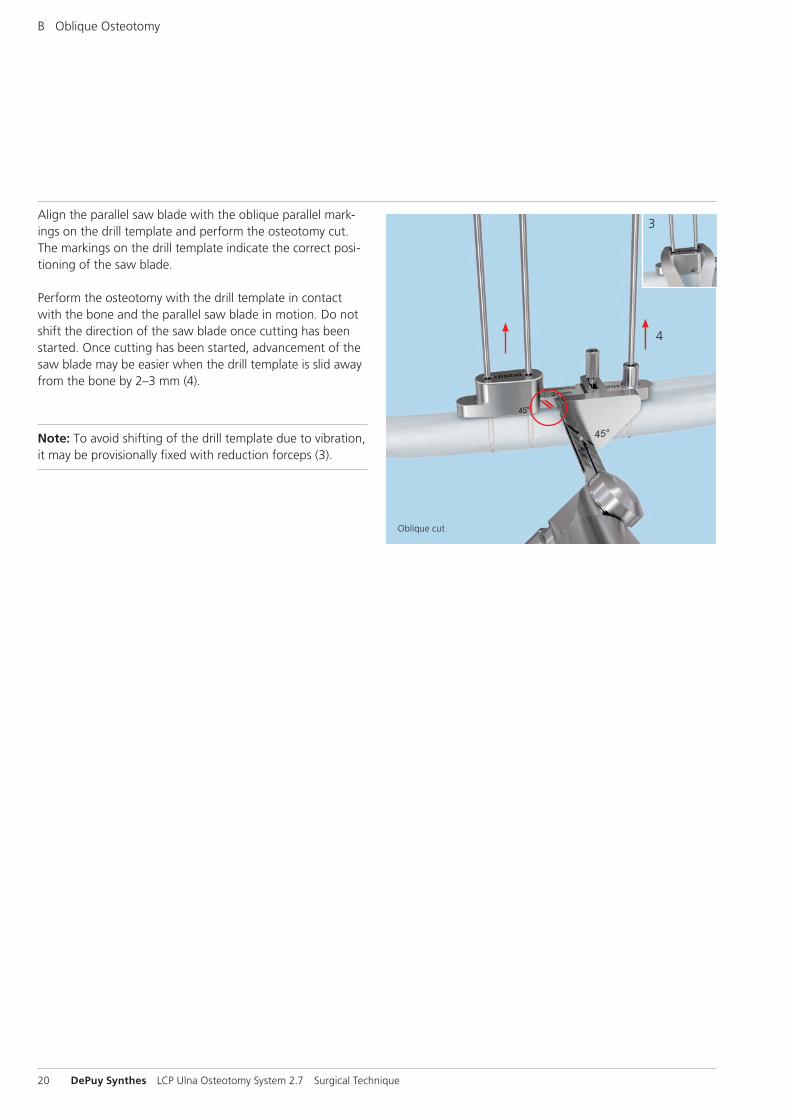
Align the parallel saw blade with the oblique parallel mark-ings on the drill template and perform the osteotomy cut. The markings on the drill template indicate the correct posi-tioning of the saw blade.
Perform the osteotomy with the drill template in contactwith the bone and the parallel saw blade in motion. Do not shift the direction of the saw blade once cutting has been started. Once cutting has been started, advancement of the saw blade may be easier when the drill template is slid away from the bone by 2–3 mm (4).
Note: To avoid shifting of the drill template due to vibration, it may be provisionally fixed with reduction forceps (3).
Oblique cut
LCP Ulna Osteotomy System 2.7 Surgical Technique DePuy Synthes 21
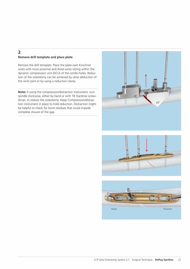
2Remove drill template and place plate
Remove the drill template. Place the plate over Kirschner wires with most proximal and distal wires sitting within the dynamic compression unit (DCU) of the combi-holes. Reduc-tion of the osteotomy can be achieved by ulnar abduction of the wrist joint or by using a reduction clamp.
Note: If using the compression/distraction instrument, turn spindle clockwise, either by hand or with T8 Stardrive screw-driver, to reduce the osteotomy. Keep Compression/distrac-tion instrument in place to hold reduction. Distraction might be helpful to check for bone residues that could impede complete closure of the gap.
Distal Proximal
22 DePuy Synthes LCP Ulna Osteotomy System 2.7 Surgical Technique
B Oblique Osteotomy
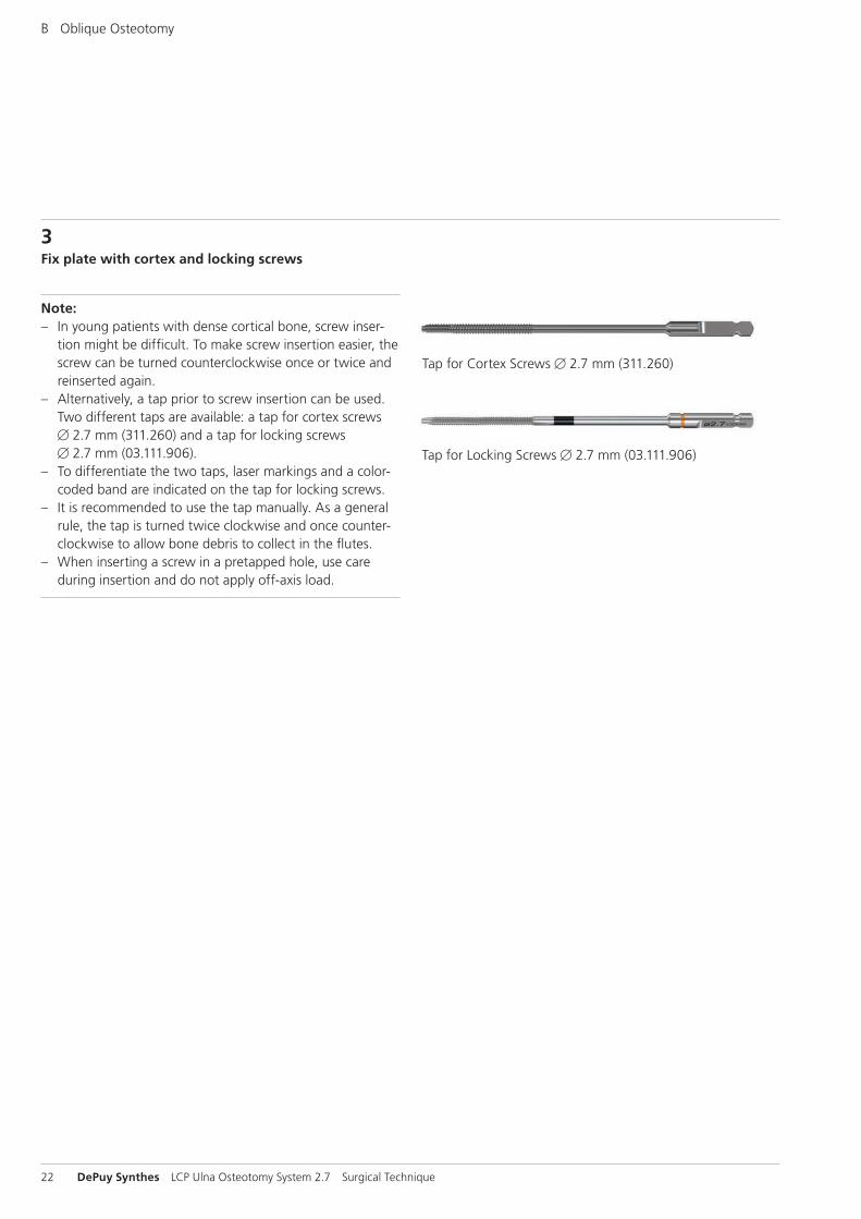
3Fix plate with cortex and locking screws
Note: – In young patients with dense cortical bone, screw inser-
tion might be difficult. To make screw insertion easier, the screw can be turned counterclockwise once or twice and reinserted again.
– Alternatively, a tap prior to screw insertion can be used. Two different taps are available: a tap for cortex screws B 2.7 mm (311.260) and a tap for locking screws B 2.7 mm (03.111.906).
– To differentiate the two taps, laser markings and a color- coded band are indicated on the tap for locking screws.
– It is recommended to use the tap manually. As a general rule, the tap is turned twice clockwise and once counter-clockwise to allow bone debris to collect in the flutes.
– When inserting a screw in a pretapped hole, use care during insertion and do not apply off-axis load.
Tap for Cortex Screws B 2.7 mm (311.260)
Tap for Locking Screws B 2.7 mm (03.111.906)
LCP Ulna Osteotomy System 2.7 Surgical Technique DePuy Synthes 23
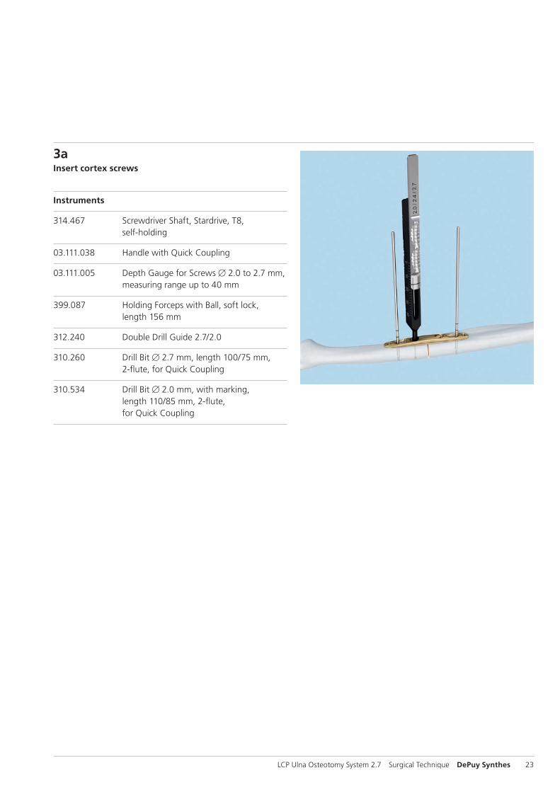
3aInsert cortex screws
Instruments
314.467 Screwdriver Shaft, Stardrive, T8, self-holding
03.111.038 Handle with Quick Coupling
03.111.005 Depth Gauge for Screws B 2.0 to 2.7 mm, measuring range up to 40 mm
399.087 Holding Forceps with Ball, soft lock, length 156 mm
312.240 Double Drill Guide 2.7/2.0
310.260 Drill Bit B 2.7 mm, length 100/75 mm, 2-flute, for Quick Coupling
310.534 Drill Bit B 2.0 mm, with marking, length 110/85 mm, 2-flute, for Quick Coupling
1
24 DePuy Synthes LCP Ulna Osteotomy System 2.7 Surgical Technique
B Oblique Osteotomy
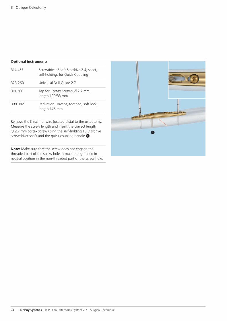
Optional instruments
314.453 Screwdriver Shaft Stardrive 2.4, short, self-holding, for Quick Coupling
323.260 Universal Drill Guide 2.7
311.260 Tap for Cortex Screws B 2.7 mm, length 100/33 mm
399.082 Reduction Forceps, toothed, soft lock, length 146 mm
Remove the Kirschner wire located distal to the osteotomy. Measure the screw length and insert the correct length B 2.7 mm cortex screw using the self-holding T8 Stardrive screwdriver shaft and the quick coupling handle 1.
Note: Make sure that the screw does not engage the threaded part of the screw hole. It must be tightened in-neutral position in the non-threaded part of the screw hole.
2
4
1
3
12
123
LCP Ulna Osteotomy System 2.7 Surgical Technique DePuy Synthes 25
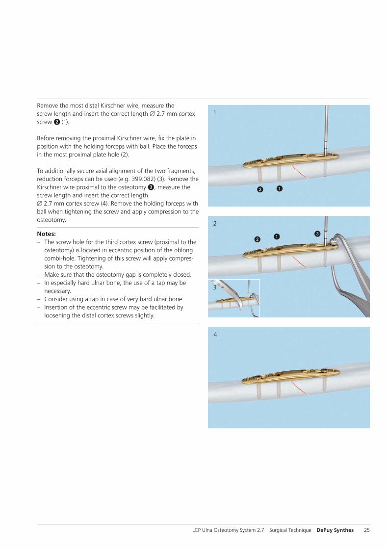
Remove the most distal Kirschner wire, measure the screw length and insert the correct length B 2.7 mm cortex screw 2 (1).
Before removing the proximal Kirschner wire, fix the plate in position with the holding forceps with ball. Place the forceps in the most proximal plate hole (2).
To additionally secure axial alignment of the two fragments, reduction forceps can be used (e.g. 399.082) (3). Remove the Kirschner wire proximal to the osteotomy 3, measure the screw length and insert the correct length B 2.7 mm cortex screw (4). Remove the holding forceps with ball when tightening the screw and apply compression to the osteotomy.
Notes: – The screw hole for the third cortex screw (proximal to the
osteotomy) is located in eccentric position of the oblong combi-hole. Tightening of this screw will apply compres-sion to the osteotomy.
– Make sure that the osteotomy gap is completely closed. – In especially hard ulnar bone, the use of a tap may be
necessary. – Consider using a tap in case of very hard ulnar bone – Insertion of the eccentric screw may be facilitated by
loosening the distal cortex screws slightly.
26 DePuy Synthes LCP Ulna Osteotomy System 2.7 Surgical Technique
B Oblique Osteotomy
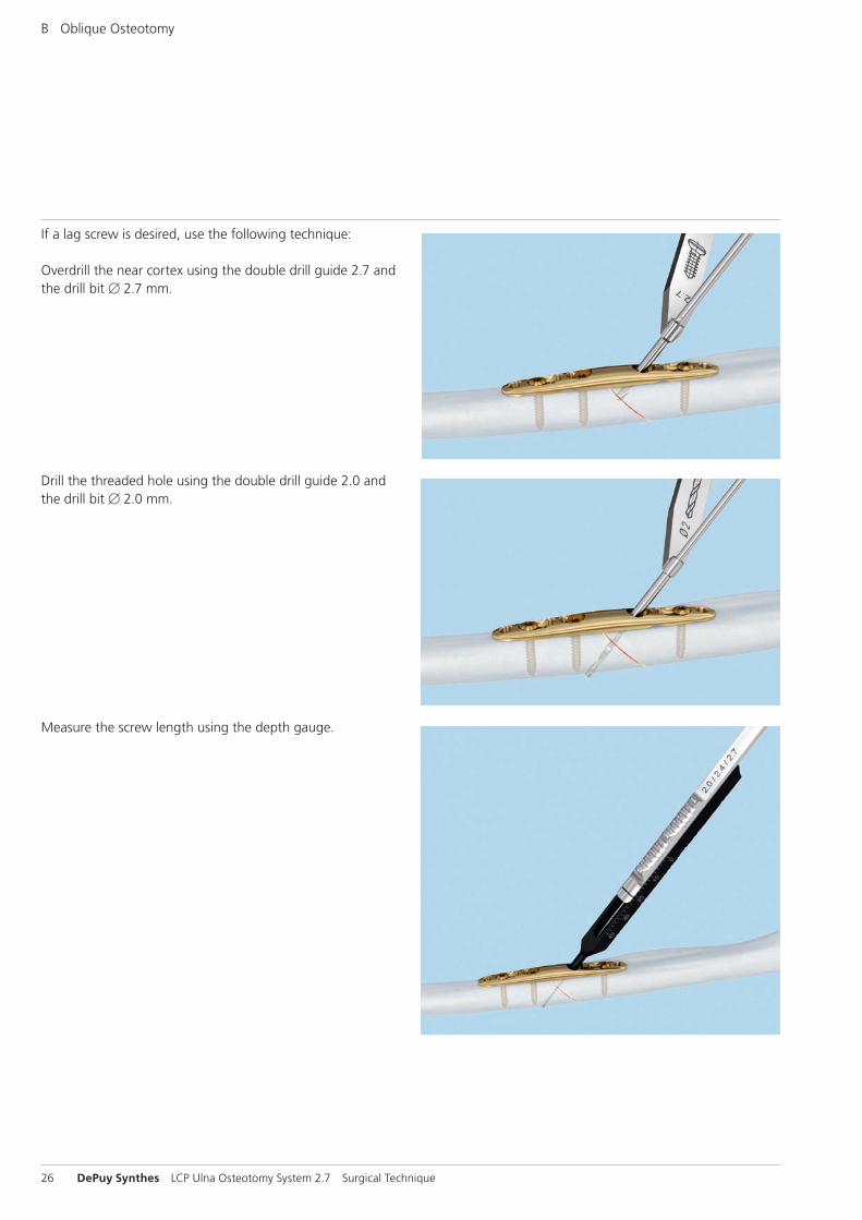
If a lag screw is desired, use the following technique:
Overdrill the near cortex using the double drill guide 2.7 and the drill bit B 2.7 mm.
Drill the threaded hole using the double drill guide 2.0 and the drill bit B 2.0 mm.
Measure the screw length using the depth gauge.
LCP Ulna Osteotomy System 2.7 Surgical Technique DePuy Synthes 27
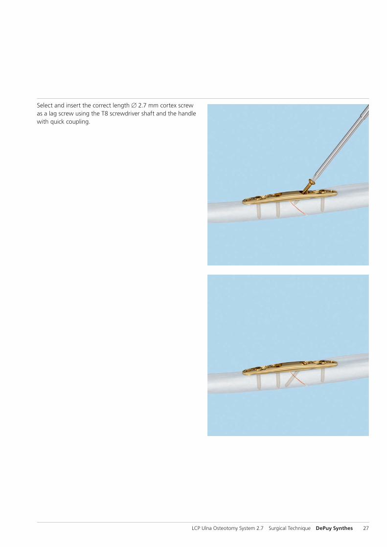
Select and insert the correct length B 2.7 mm cortex screw as a lag screw using the T8 screwdriver shaft and the handle with quick coupling.
28 DePuy Synthes LCP Ulna Osteotomy System 2.7 Surgical Technique
B Oblique Osteotomy
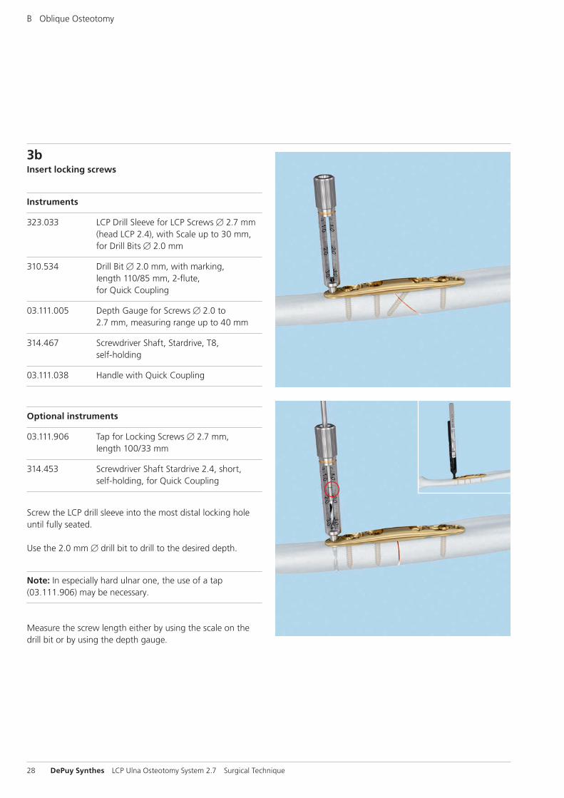
3bInsert locking screws
Instruments
323.033 LCP Drill Sleeve for LCP Screws B 2.7 mm (head LCP 2.4), with Scale up to 30 mm, for Drill Bits B 2.0 mm
310.534 Drill Bit B 2.0 mm, with marking, length 110/85 mm, 2-flute, for Quick Coupling
03.111.005 Depth Gauge for Screws B 2.0 to 2.7 mm, measuring range up to 40 mm
314.467 Screwdriver Shaft, Stardrive, T8, self-holding
03.111.038 Handle with Quick Coupling
Optional instruments
03.111.906 Tap for Locking Screws B 2.7 mm, length 100/33 mm
314.453 Screwdriver Shaft Stardrive 2.4, short, self-holding, for Quick Coupling
Screw the LCP drill sleeve into the most distal locking hole until fully seated.
Use the 2.0 mm B drill bit to drill to the desired depth.
Note: In especially hard ulnar one, the use of a tap (03.111.906) may be necessary.
Measure the screw length either by using the scale on the drill bit or by using the depth gauge.
LCP Ulna Osteotomy System 2.7 Surgical Technique DePuy Synthes 29
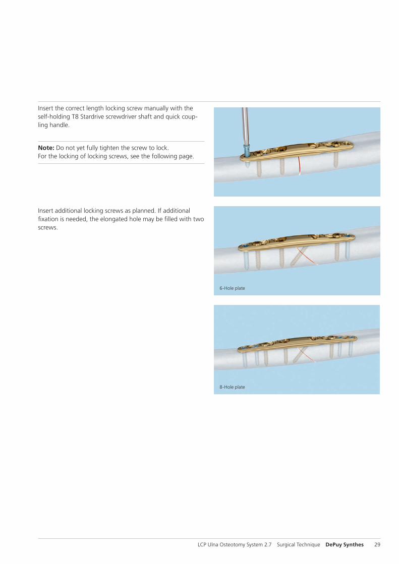
Insert the correct length locking screw manually with the self-holding T8 Stardrive screwdriver shaft and quick coup-ling handle.
Note: Do not yet fully tighten the screw to lock. For the locking of locking screws, see the following page.
Insert additional locking screws as planned. If additional fixation is needed, the elongated hole may be filled with two screws.
6-Hole plate
8-Hole plate
30 DePuy Synthes LCP Ulna Osteotomy System 2.7 Surgical Technique
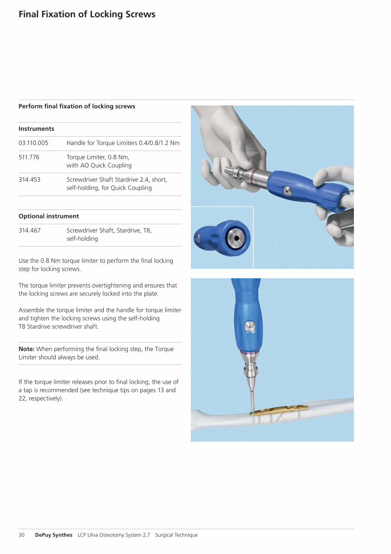
Final Fixation of Locking Screws
Perform final fixation of locking screws
Instruments
03.110.005 Handle for Torque Limiters 0.4/0.8/1.2 Nm
511.776 Torque Limiter, 0.8 Nm, with AO Quick Coupling
314.453 Screwdriver Shaft Stardrive 2.4, short, self-holding, for Quick Coupling
Optional instrument
314.467 Screwdriver Shaft, Stardrive, T8, self-holding
Use the 0.8 Nm torque limiter to perform the final locking step for locking screws.
The torque limiter prevents overtightening and ensures that the locking screws are securely locked into the plate.
Assemble the torque limiter and the handle for torque limiter and tighten the locking screws using the self-holding T8 Stardrive screwdriver shaft.
Note: When performing the final locking step, the Torque Limiter should always be used.
If the torque limiter releases prior to final locking, the use of a tap is recommended (see technique tips on pages 13 and 22, respectively).
AB A B
1
21
LCP Ulna Osteotomy System 2.7 Surgical Technique DePuy Synthes 31
Alternative Technique
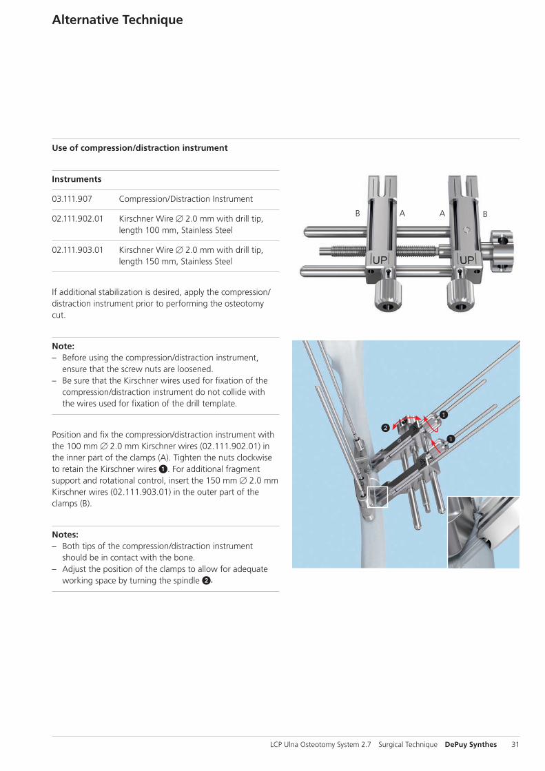
Use of compression/distraction instrument
Instruments
03.111.907 Compression/Distraction Instrument
02.111.902.01 Kirschner Wire B 2.0 mm with drill tip, length 100 mm, Stainless Steel
02.111.903.01 Kirschner Wire B 2.0 mm with drill tip, length 150 mm, Stainless Steel
If additional stabilization is desired, apply the compression/ distraction instrument prior to performing the osteotomy cut.
Note: – Before using the compression/distraction instrument,
ensure that the screw nuts are loosened. – Be sure that the Kirschner wires used for fixation of the
compression/distraction instrument do not collide with the wires used for fixation of the drill template.
Position and fix the compression/distraction instrument with the 100 mm B 2.0 mm Kirschner wires (02.111.902.01) in the inner part of the clamps (A). Tighten the nuts clockwise to retain the Kirschner wires 1. For additional fragment support and rotational control, insert the 150 mm B 2.0 mm Kirschner wires (02.111.903.01) in the outer part of the clamps (B).
Notes: – Both tips of the compression/distraction instrument
should be in contact with the bone. – Adjust the position of the clamps to allow for adequate
working space by turning the spindle 2.
15 mm10 mm
32 DePuy Synthes LCP Ulna Osteotomy System 2.7 Surgical Technique
Alternative Technique
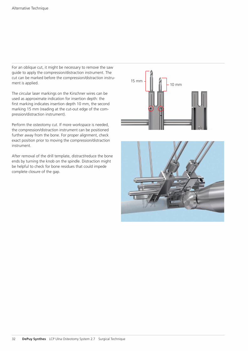
For an oblique cut, it might be necessary to remove the saw guide to apply the compression/distraction instrument. The cut can be marked before the compression/distraction instru-ment is applied.
The circular laser markings on the Kirschner wires can be used as approximate indication for insertion depth: the first marking indicates insertion depth 10 mm, the second marking 15 mm (reading at the cut-out edge of the com-pression/distraction instrument).
Perform the osteotomy cut. If more workspace is needed, the compression/distraction instrument can be positioned further away from the bone. For proper alignment, check exact position prior to moving the compression/distraction instrument.
After removal of the drill template, distract/reduce the bone ends by turning the knob on the spindle. Distraction might be helpful to check for bone residues that could impede complete closure of the gap.
LCP Ulna Osteotomy System 2.7 Surgical Technique DePuy Synthes 33
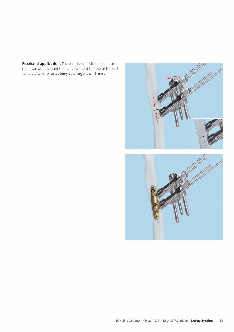
Freehand application: The compression/distraction instru-ment can also be used freehand (without the use of the drill template) and for osteotomy cuts larger than 5 mm.
34 DePuy Synthes LCP Ulna Osteotomy System 2.7 Surgical Technique
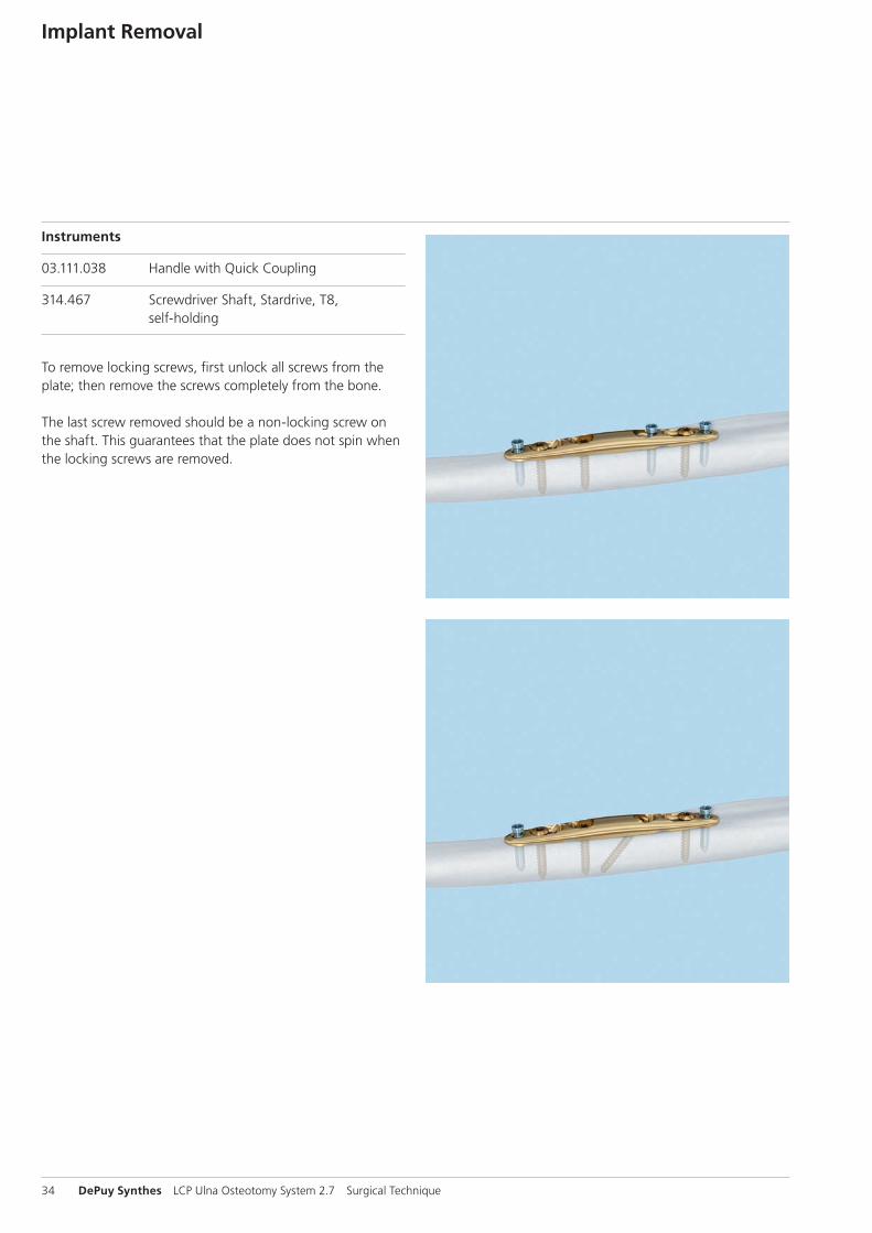
Instruments
03.111.038 Handle with Quick Coupling
314.467 Screwdriver Shaft, Stardrive, T8, self-holding
To remove locking screws, first unlock all screws from theplate; then remove the screws completely from the bone.
The last screw removed should be a non-locking screw onthe shaft. This guarantees that the plate does not spin when the locking screws are removed.
Implant Removal
LCP Ulna Osteotomy System 2.7 Surgical Technique DePuy Synthes 35
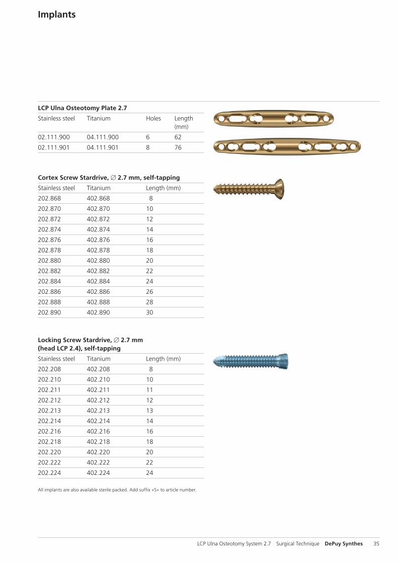
Implants
LCP Ulna Osteotomy Plate 2.7
Stainless steel Titanium Holes Length (mm)
02.111.900 04.111.900 6 62
02.111.901 04.111.901 8 76
Cortex Screw Stardrive, B 2.7 mm, self-tapping
Stainless steel Titanium Length (mm)
202.868 402.868 8
202.870 402.870 10
202.872 402.872 12
202.874 402.874 14
202.876 402.876 16
202.878 402.878 18
202.880 402.880 20
202.882 402.882 22
202.884 402.884 24
202.886 402.886 26
202.888 402.888 28
202.890 402.890 30
Locking Screw Stardrive, B 2.7 mm (head LCP 2.4), self-tapping
Stainless steel Titanium Length (mm)
202.208 402.208 8
202.210 402.210 10
202.211 402.211 11
202.212 402.212 12
202.213 402.213 13
202.214 402.214 14
202.216 402.216 16
202.218 402.218 18
202.220 402.220 20
202.222 402.222 22
202.224 402.224 24
All implants are also available sterile packed. Add suffix «S» to article number.
2
1
36 DePuy Synthes LCP Ulna Osteotomy System 2.7 Surgical Technique
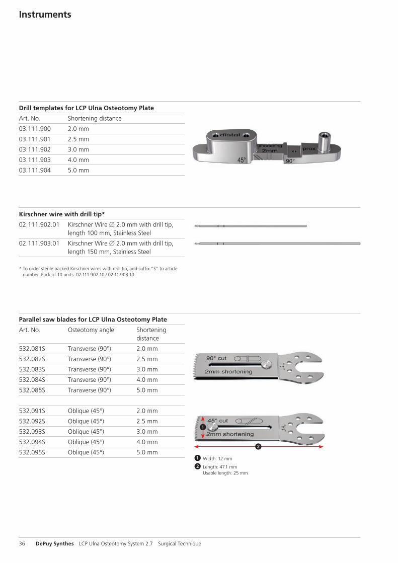
Instruments
Drill templates for LCP Ulna Osteotomy Plate
Art. No. Shortening distance
03.111.900 2.0 mm
03.111.901 2.5 mm
03.111.902 3.0 mm
03.111.903 4.0 mm
03.111.904 5.0 mm
Kirschner wire with drill tip*
02.111.902.01 Kirschner Wire B 2.0 mm with drill tip, length 100 mm, Stainless Steel
02.111.903.01 Kirschner Wire B 2.0 mm with drill tip, length 150 mm, Stainless Steel
* To order sterile packed Kirschner wires with drill tip, add suffix “S” to article number. Pack of 10 units: 02.111.902.10 / 02.11.903.10
Parallel saw blades for LCP Ulna Osteotomy Plate
Art. No. Osteotomy angle Shortening distance
532.081S Transverse (90°) 2.0 mm
532.082S Transverse (90°) 2.5 mm
532.083S Transverse (90°) 3.0 mm
532.084S Transverse (90°) 4.0 mm
532.085S Transverse (90°) 5.0 mm
532.091S Oblique (45°) 2.0 mm
532.092S Oblique (45°) 2.5 mm
532.093S Oblique (45°) 3.0 mm
532.094S Oblique (45°) 4.0 mm
532.095S Oblique (45°) 5.0 mm1 Width: 12 mm
2 Length: 47.1 mm Usable length: 25 mm
LCP Ulna Osteotomy System 2.7 Surgical Technique DePuy Synthes 37
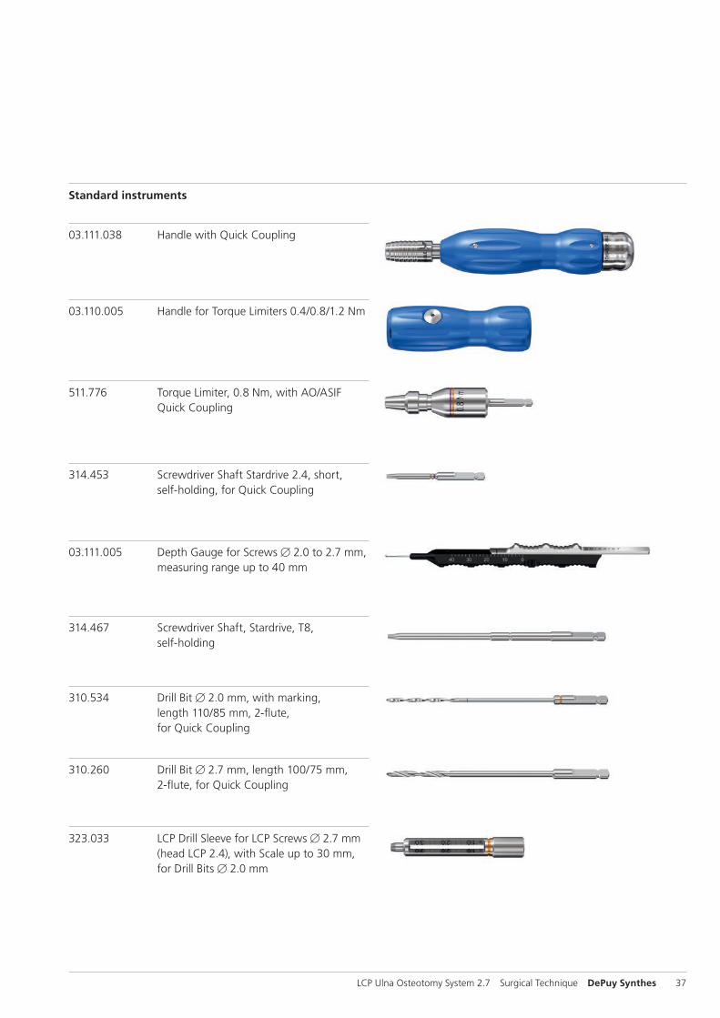
Standard instruments
03.111.005 Depth Gauge for Screws B 2.0 to 2.7 mm, measuring range up to 40 mm
314.467 Screwdriver Shaft, Stardrive, T8, self-holding
310.534 Drill Bit B 2.0 mm, with marking, length 110/85 mm, 2-flute, for Quick Coupling
310.260 Drill Bit B 2.7 mm, length 100/75 mm, 2-flute, for Quick Coupling
323.033 LCP Drill Sleeve for LCP Screws B 2.7 mm (head LCP 2.4), with Scale up to 30 mm, for Drill Bits B 2.0 mm
03.110.005 Handle for Torque Limiters 0.4/0.8/1.2 Nm
511.776 Torque Limiter, 0.8 Nm, with AO/ASIF Quick Coupling
314.453 Screwdriver Shaft Stardrive 2.4, short, self-holding, for Quick Coupling
03.111.038 Handle with Quick Coupling
38 DePuy Synthes LCP Ulna Osteotomy System 2.7 Surgical Technique
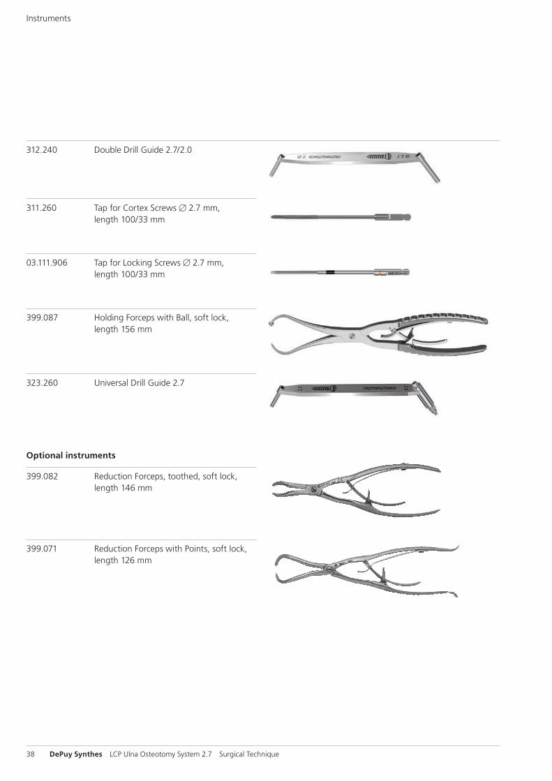
Instruments
312.240 Double Drill Guide 2.7/2.0
311.260 Tap for Cortex Screws B 2.7 mm, length 100/33 mm
03.111.906 Tap for Locking Screws B 2.7 mm, length 100/33 mm
399.087 Holding Forceps with Ball, soft lock, length 156 mm
323.260 Universal Drill Guide 2.7
Optional instruments
399.082 Reduction Forceps, toothed, soft lock, length 146 mm
399.071 Reduction Forceps with Points, soft lock, length 126 mm
LCP Ulna Osteotomy System 2.7 Surgical Technique DePuy Synthes 39
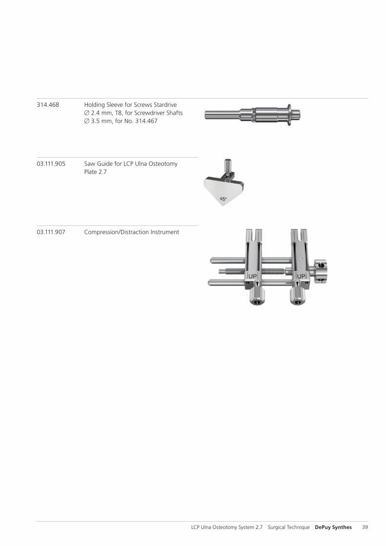
314.468 Holding Sleeve for Screws Stardrive B 2.4 mm, T8, for Screwdriver Shafts B 3.5 mm, for No. 314.467
03.111.905 Saw Guide for LCP Ulna Osteotomy Plate 2.7
03.111.907 Compression/Distraction Instrument
40 DePuy Synthes LCP Ulna Osteotomy System 2.7 Surgical Technique
MRI Information
Torque, Displacement and Image Artifacts according to ASTM F 2213-06, ASTM F 2052-06e1 and ASTM F 2119-07Non-clinical testing of worst case scenario in a 3 T MRI system did not reveal any relevant torque or displacement of the construct for an experimentally measured local spatial gradient of the magnetic field of 3.69 T/m. The largest image artifact extended approximately 169 mm from the construct when scanned using the Gradient Echo (GE). Testing was conducted on a 3 T MRI system.
Radio-Frequency-(RF-)induced heating according to ASTM F 2182-11aNon-clinical electromagnetic and thermal testing of worst case scenario lead to peak temperature rise of 9.5 °C with an average temperature rise of 6.6 °C (1.5 T) and a peak temperature rise of 5.9 °C (3 T) under MRI Conditions using RF Coils (whole body averaged specific absorption rate [SAR] of 2 W/kg for 6 minutes [1.5 T] and for 15 minutes [3 T]).
Precautions: The above mentioned test relies on non-clini - cal testing. The actual temperature rise in the patient will depend on a variety of factors beyond the SAR and time of RF application. Thus, it is recommended to pay particular attention to the following points: – It is recommended to thoroughly monitor patients under-
going MR scanning for perceived temperature and/or pain sensations.
– Patients with impaired thermoregulation or temperature sensation should be excluded from MR scanning proce - dures.
– Generally, it is recommended to use a MR system with low field strength in the presence of conductive implants. The employed specific absorption rate (SAR) should be reduced as far as possible.
– Using the ventilation system may further contribute to reduce temperature increase in the body.


0123
Synthes GmbHEimattstrasse 34436 OberdorfSwitzerlandTel: +41 61 965 61 11Fax: +41 61 965 66 00www.depuysynthes.com
Not all products are currently available in all markets.
This publication is not intended for distribution in the USA.
All surgical techniques are available as PDF files at www.depuysynthes.com/ifu ©
DeP
uy S
ynth
es T
raum
a, a
div
isio
n of
Syn
thes
Gm
bH. 2
016.
A
ll rig
hts
rese
rved
. 03
6.0
01.1
30
DSE
M/T
RM
/051
4/0
076(
2)
03/1
6