Embed Size (px)
Citation preview
LCRA Transmission Services Corporation
Facility Connection Requirements
April 2017
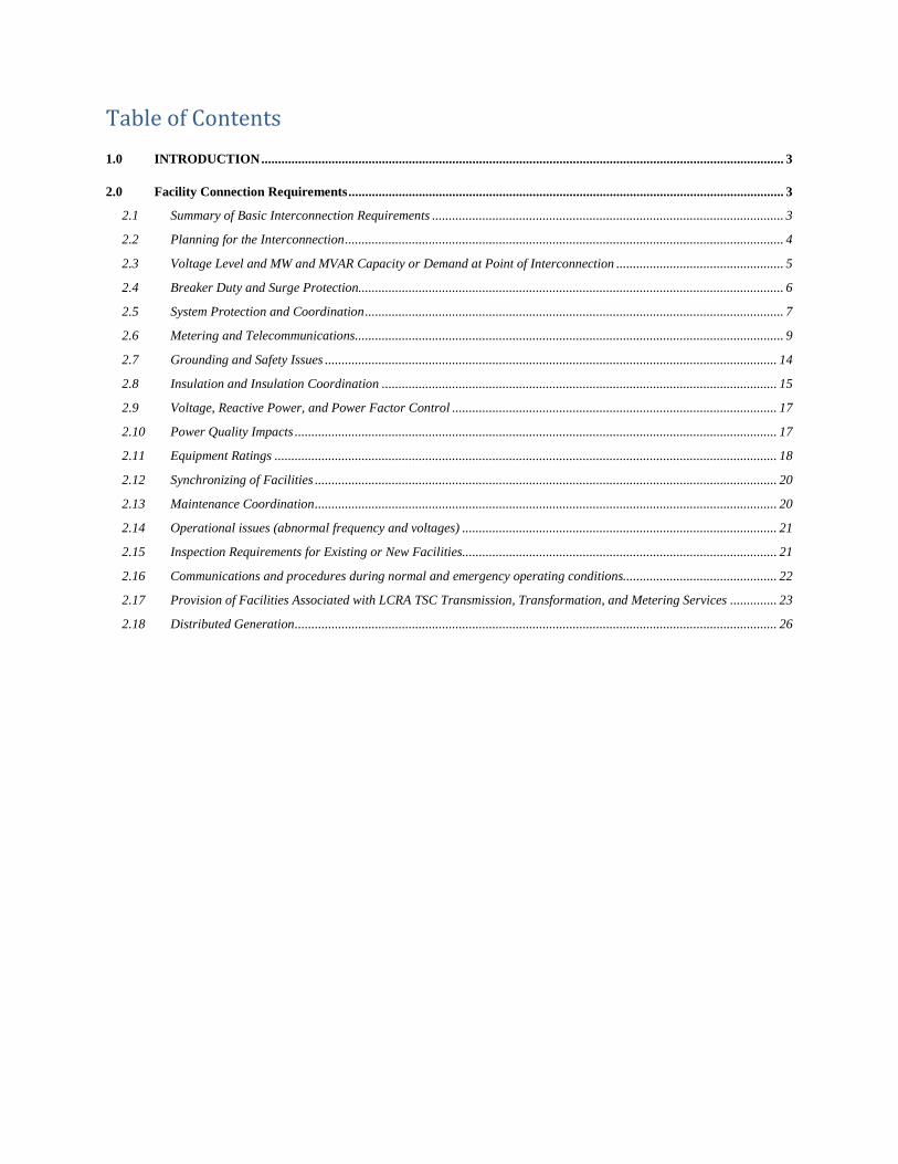
Table of Contents
1.0 INTRODUCTION ............................................................................................................................................................ 3
2.0 Facility Connection Requirements .................................................................................................................................. 3
2.1 Summary of Basic Interconnection Requirements ......................................................................................................... 3
2.2 Planning for the Interconnection ................................................................................................................................... 4
2.3 Voltage Level and MW and MVAR Capacity or Demand at Point of Interconnection .................................................. 5
2.4 Breaker Duty and Surge Protection............................................................................................................................... 6
2.5 System Protection and Coordination ............................................................................................................................. 7
2.6 Metering and Telecommunications ................................................................................................................................ 9
2.7 Grounding and Safety Issues ....................................................................................................................................... 14
2.8 Insulation and Insulation Coordination ...................................................................................................................... 15
2.9 Voltage, Reactive Power, and Power Factor Control ................................................................................................. 17
2.10 Power Quality Impacts ................................................................................................................................................ 17
2.11 Equipment Ratings ...................................................................................................................................................... 18
2.12 Synchronizing of Facilities .......................................................................................................................................... 20
2.13 Maintenance Coordination .......................................................................................................................................... 20
2.14 Operational issues (abnormal frequency and voltages) .............................................................................................. 21
2.15 Inspection Requirements for Existing or New Facilities .............................................................................................. 21
2.16 Communications and procedures during normal and emergency operating conditions.............................................. 22
2.17 Provision of Facilities Associated with LCRA TSC Transmission, Transformation, and Metering Services .............. 23
2.18 Distributed Generation ................................................................................................................................................ 26
LCRA Transmission Services Corporation - Facility Connection Requirements - April 2017
Page 3 of 27
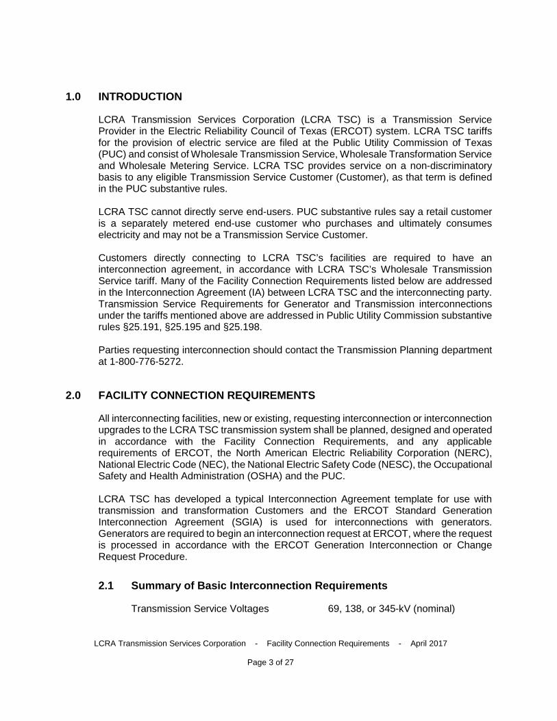
1.0 INTRODUCTION
LCRA Transmission Services Corporation (LCRA TSC) is a Transmission Service Provider in the Electric Reliability Council of Texas (ERCOT) system. LCRA TSC tariffs for the provision of electric service are filed at the Public Utility Commission of Texas (PUC) and consist of Wholesale Transmission Service, Wholesale Transformation Service and Wholesale Metering Service. LCRA TSC provides service on a non-discriminatory basis to any eligible Transmission Service Customer (Customer), as that term is defined in the PUC substantive rules.
LCRA TSC cannot directly serve end-users. PUC substantive rules say a retail customer is a separately metered end-use customer who purchases and ultimately consumes electricity and may not be a Transmission Service Customer.
Customers directly connecting to LCRA TSC’s facilities are required to have an interconnection agreement, in accordance with LCRA TSC’s Wholesale Transmission Service tariff. Many of the Facility Connection Requirements listed below are addressed in the Interconnection Agreement (IA) between LCRA TSC and the interconnecting party. Transmission Service Requirements for Generator and Transmission interconnections under the tariffs mentioned above are addressed in Public Utility Commission substantive rules §25.191, §25.195 and §25.198.
Parties requesting interconnection should contact the Transmission Planning department at 1-800-776-5272.
2.0 FACILITY CONNECTION REQUIREMENTS
All interconnecting facilities, new or existing, requesting interconnection or interconnection upgrades to the LCRA TSC transmission system shall be planned, designed and operated in accordance with the Facility Connection Requirements, and any applicable requirements of ERCOT, the North American Electric Reliability Corporation (NERC), National Electric Code (NEC), the National Electric Safety Code (NESC), the Occupational Safety and Health Administration (OSHA) and the PUC.
LCRA TSC has developed a typical Interconnection Agreement template for use with transmission and transformation Customers and the ERCOT Standard Generation Interconnection Agreement (SGIA) is used for interconnections with generators. Generators are required to begin an interconnection request at ERCOT, where the request is processed in accordance with the ERCOT Generation Interconnection or Change Request Procedure.
2.1 Summary of Basic Interconnection Requirements
Transmission Service Voltages 69, 138, or 345-kV (nominal)
LCRA Transmission Services Corporation - Facility Connection Requirements - April 2017
Page 4 of 27
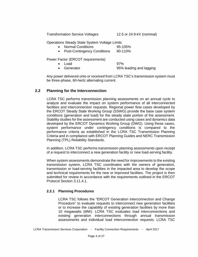
Transformation Service Voltages 12.5 or 24.9-kV (nominal)
Operations Steady State System Voltage Limits • Normal Conditions 95-105% • Post-Contingency Conditions 90-110%
Power Factor (ERCOT requirements) • Load 97% • Generator 95% leading and lagging
Any power delivered onto or received from LCRA TSC’s transmission system must be three-phase, 60-hertz alternating current.
2.2 Planning for the Interconnection
LCRA TSC performs transmission planning assessments on an annual cycle to analyze and evaluate the impact on system performance of all interconnected facilities and interconnection requests. Regional power flow cases developed by the ERCOT Steady State Working Group (SSWG) provide the base case system conditions (generation and load) for the steady state portion of the assessment. Stability studies for the assessment are conducted using cases and dynamics data developed by the ERCOT Dynamics Working Group (DWG). Using these cases, system performance under contingency conditions is compared to the performance criteria as established in the LCRA TSC Transmission Planning Criteria and in compliance with ERCOT Planning Guides and NERC Transmission Planning (TPL) Reliability Standards.
In addition, LCRA TSC performs transmission planning assessments upon receipt of a request to interconnect a new generation facility or new load-serving facility.
When system assessments demonstrate the need for improvements to the existing transmission system, LCRA TSC coordinates with the owners of generation, transmission or load-serving facilities in the impacted area to develop the scope and technical requirements for the new or improved facilities. The project is then submitted for review in accordance with the requirements outlined in the ERCOT Protocol Section 3.11.4.1.
2.2.1 Planning Procedures
LCRA TSC follows the “ERCOT Generation Interconnection and Change Procedure” to evaluate requests to interconnect new generation facilities or to increase the capability of existing generation facilities by more than 10 megawatts (MW). LCRA TSC evaluates load interconnections and existing generation interconnections through annual transmission assessments and individual load interconnection requests. LCRA TSC
LCRA Transmission Services Corporation - Facility Connection Requirements - April 2017
Page 5 of 27
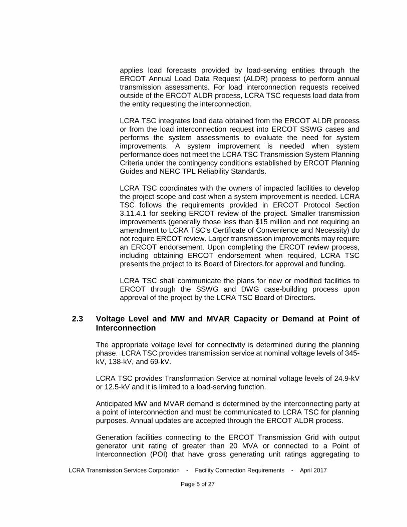
applies load forecasts provided by load-serving entities through the ERCOT Annual Load Data Request (ALDR) process to perform annual transmission assessments. For load interconnection requests received outside of the ERCOT ALDR process, LCRA TSC requests load data from the entity requesting the interconnection.
LCRA TSC integrates load data obtained from the ERCOT ALDR process or from the load interconnection request into ERCOT SSWG cases and performs the system assessments to evaluate the need for system improvements. A system improvement is needed when system performance does not meet the LCRA TSC Transmission System Planning Criteria under the contingency conditions established by ERCOT Planning Guides and NERC TPL Reliability Standards.
LCRA TSC coordinates with the owners of impacted facilities to develop the project scope and cost when a system improvement is needed. LCRA TSC follows the requirements provided in ERCOT Protocol Section 3.11.4.1 for seeking ERCOT review of the project. Smaller transmission improvements (generally those less than $15 million and not requiring an amendment to LCRA TSC’s Certificate of Convenience and Necessity) do not require ERCOT review. Larger transmission improvements may require an ERCOT endorsement. Upon completing the ERCOT review process, including obtaining ERCOT endorsement when required, LCRA TSC presents the project to its Board of Directors for approval and funding.
LCRA TSC shall communicate the plans for new or modified facilities to ERCOT through the SSWG and DWG case-building process upon approval of the project by the LCRA TSC Board of Directors.
2.3 Voltage Level and MW and MVAR Capacity or Demand at Point of Interconnection
The appropriate voltage level for connectivity is determined during the planning phase. LCRA TSC provides transmission service at nominal voltage levels of 345-kV, 138-kV, and 69-kV.
LCRA TSC provides Transformation Service at nominal voltage levels of 24.9-kV or 12.5-kV and it is limited to a load-serving function.
Anticipated MW and MVAR demand is determined by the interconnecting party at a point of interconnection and must be communicated to LCRA TSC for planning purposes. Annual updates are accepted through the ERCOT ALDR process.
Generation facilities connecting to the ERCOT Transmission Grid with output generator unit rating of greater than 20 MVA or connected to a Point of Interconnection (POI) that have gross generating unit ratings aggregating to
LCRA Transmission Services Corporation - Facility Connection Requirements - April 2017
Page 6 of 27
greater than 20 MVA must provide ERCOT Voltage Support Services (VSS) as required under ERCOT Nodal Protocol 3.15, Voltage Support.
2.4 Breaker Duty and Surge Protection
LCRA TSC shall determine the site-specific short-circuit current available for the point of interconnection and shall communicate that rating to the Customer. LCRA TSC-owned circuit breakers and circuit switchers (interrupting devices) at the point of interconnection shall have ratings that meet or exceed the following requirements:
a. Gas and oil circuit breakers shall have an interrupting rating of be at least 110 and 120 percent respectively of the maximum available close-in fault at the point of application.
b. Circuit switchers shall have an interrupting rating of at least 110 percent of the maximum available close-in fault at the point of application.
Customer-owned circuit breakers and circuit switchers (interrupting devices) at the point of interconnection shall have ratings that allow for safe and reliable operation at all times under all fault conditions.
Customer shall provide LCRA TSC with nameplate data for interrupting devices on an as-needed basis. LCRA TSC shall notify Customer when anticipated available short circuit current exceeds the requirements stated above. Customer is responsible for planning replacement or upgrade of customer-owned interrupting devices.
Station class arresters, of the metal oxide varistor design, are recommended for overvoltage protection of transmission equipment.
Distribution or intermediate class type surge arresters should be used only on distribution equipment.
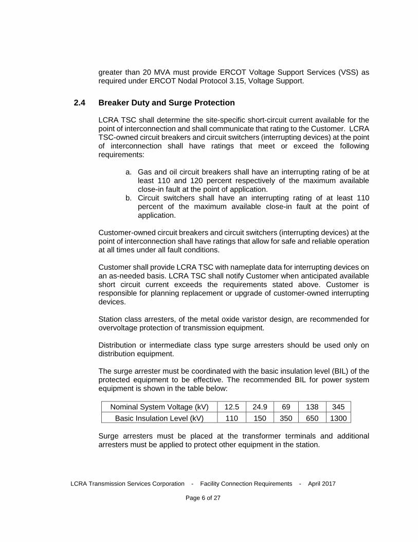
The surge arrester must be coordinated with the basic insulation level (BIL) of the protected equipment to be effective. The recommended BIL for power system equipment is shown in the table below:
Nominal System Voltage (kV) 12.5 24.9 69 138 345
Basic Insulation Level (kV) 110 150 350 650 1300
Surge arresters must be placed at the transformer terminals and additional arresters must be applied to protect other equipment in the station.
LCRA Transmission Services Corporation - Facility Connection Requirements - April 2017
Page 7 of 27
2.5 System Protection and Coordination
Project-specific requirements for system protection and coordination are determined during the conceptual design and detailed design phases, and documented in the engineering prints and relay coordination files.
General requirements for system protection and coordination are found in the ERCOT Nodal Operating Guides, see Section 6.2.
Fault clearing shall utilize high-speed, pilot-assisted schemes for transmission elements above 100-kV.
For interconnections of power transformers with capacity of 10 megavolt ampere (MVA) and below, fuse protection is allowed if the utilization of the fuse protections does not compromise reliability. However, for interconnection of power transformers above 10 MVA, a fully-relayed circuit switcher or circuit breaker installation is required.
Distribution schemes shall be coordinated with the transformer owner.
Customer protection system equipment shall be provided to LCRA TSC to allow for overlapping zones of protection. Examples include, but are not limited to, customer’s provision of transformer CTs for bus differential protection, customer’s provision of breaker CTs for bus differential protection, etc.
For transformation and distribution (i.e., load-serving) interconnecting facilities, the Interconnection Agreement (Article 6) includes, in part, protection requirements.
For Generation facilities, the SGIA includes Article 5.6 addressing System Protection and other Control Requirements. Additionally, LCRA TSC includes the following requirements in generation interconnection agreements (typically found in Exhibit “C”, Item 10):
“System Protection Equipment: Plant and the Generator Interconnection Facilities shall be designed to isolate any fault or to disconnect from or isolate any abnormality that would negatively affect the ERCOT system. The Generator shall be responsible for protection of its facilities. In particular, Generator shall provide relays, circuit breakers and all other devices necessary to promptly remove any fault contribution of the generation equipment to any short circuit occurring on the TSP system. Such protective equipment shall include, without limitation, a disconnect device or switch with the appropriate interrupting capability to be located within the Generator Interconnection Facilities and the TSP Interconnection Facilities at a site mutually agreed by both parties. In addition to faults within the Plant and the Generator Interconnection Facilities, Generator shall be responsible for protection of such facilities from such
LCRA Transmission Services Corporation - Facility Connection Requirements - April 2017
Page 8 of 27
conditions as, over-frequency or under-frequency, over-voltage or under-voltage, and non-cleared transmission system faults.
The Plant and the Generator Interconnection Facilities shall have protective relaying consistent with the protective relaying criteria described in ERCOT Requirements and NERC standards. If reasonably requested by the TSP, Generator shall, at its expense, provide corrections or additions to existing control and protective equipment required to protect the ERCOT system, or to comply with government or industry regulations or standard changes.
The Generator’s protective relay design shall incorporate necessary test switches to enable complete functional testing. Required test switches shall be placed such that they allow operation of lockout relays while preventing breaker failure schemes from operating and causing unnecessary breaker operations and tripping generator units.
Generator shall install sufficient disturbance and fault-monitoring equipment to thoroughly analyze all system disturbances of the generation system. This equipment shall monitor the voltages at major nodes of the system, current at major branches, breaker and switch positions, and enough of the dc logic in the relay control scheme to analyze a system disturbance. The TSP shall provide for disturbance and fault-monitoring equipment in its switchyard. The disturbance and fault monitoring for both Generator and TSP shall be consistent with the disturbance-monitoring requirements described in ERCOT Requirements and NERC standards.
Prior to modifying relay protection system design or relay setting involving the connecting facilities between the two Parties, Generator shall submit the proposed changes to the TSP for review and approval. TSP’s review and approval shall be for the limited purpose of determining whether such proposed changes are compatible with the ERCOT transmission system.
In accordance with Good Utility Practice, and ERCOT and NERC standards, the TSP shall determine requirements for protection of the Point of Interconnection and the zone of protection around the Point of Interconnection, and shall specify and implement protection and control schemes as necessary to meet such requirements. Generator shall have the right to review and comment on the necessary protection requirements, and such comments shall not be unreasonably refused by the TSP when determining such requirements. The TSP shall coordinate the relay system protection between Generator and the ERCOT system.
Additionally, the Generator shall provide, in PSSE or Aspen OneLiner format, the short circuit model for the Generator Interconnection Facilities, the generators and collector facilities prior to the protective relay settings being
LCRA Transmission Services Corporation - Facility Connection Requirements - April 2017
Page 9 of 27
calculated, and in no case later than 60 days prior to the initial actual in-service date.”
2.6 Metering and Telecommunications
Project specific requirements for metering and telecommunications are determined during the design phase and documented in the interconnection agreement. General requirements are listed below.
ERCOT requirements for metering and telecommunications are found in the documents referenced below:
• ERCOT Settlement Metering Operating Guide • ERCOT Nodal Operating Guides; Section 7; Telemetry and
Communication • ERCOT Nodal Protocols; Section 10: Metering
2.6.1 General Requirements
Current Transformers All metering CTs must conform to 0.3 percent accuracy or better. Each CT shall be provided with factory test reports stipulating the ratios, accuracy class and burden. Current transformers should have a burden rating of at least 1.8 ohm, but may have lower burden ratings in special circumstances depending on physical, electrical and/or economical restraints.
Voltage Transformers All voltage transformers shall conform to 0.3 percent accuracy class or better, and shall be provided with factory test reports stipulating ratio, accuracy class and burden. Voltage transformers should have a burden rating of at least Z (200 VA), but may have lower burden ratings in special circumstances depending on physical, electrical or economical restraints.
Metering Communications At a minimum, a dial-up phone line (POTS line) shall be provided for the LCRA TSC MV-90 Translations Department to interrogate the meters for power and energy billing units.
2.6.2 Generation Facilities
Article 5, Section 5.5 and Exhibit “C” of the SGIA addresses requirements for Metering and Telecommunication for Generation interconnections.
Section 5.5 of the SGIA is restated below:
LCRA Transmission Services Corporation - Facility Connection Requirements - April 2017
Page 10 of 27
“Metering and telemetry of data shall be accomplished in accordance with ERCOT Requirements. The specific metering, telemetry and communications equipment to be installed, and the data to be telemetered, are described in Exhibit “C” of the SGIA.
The TSP shall own the metering and telemetry equipment at the Point of Interconnection or mutually agreed metering point. The TSP shall provide the Generator with metering and telemetry values in accordance with ERCOT Requirements.
A minimum set of inputs to the telemetry equipment are specified in Exhibit “C” of the SGIA. Additional sets of inputs may be subsequently mutually agreed upon.
The TSP shall notify the Generator at least five working days in advance of any planned maintenance, inspection, testing or calibration of the metering equipment, unless otherwise agreed to in writing. The Generator, or its designated representative, shall have the right to be present for these activities and to receive copies of any documents related to the procedures and results.
Prior to the connection of the GIF to the TIF, acceptance tests shall be performed by the owning Party to ensure the proper functioning of all metering, telemetry and communications equipment associated with the Point of Interconnection and both Parties’ interconnection facilities, and to verify the accuracy of data being received by the TSP, ERCOT and the Generator. All acceptance tests shall be performed consistent with ERCOT Requirements.
The TSP shall, in accordance with Good Utility Practice and ERCOT Requirements, specify communications facilities necessary for the effective operation of the Plant and the GIF with the TSP System, including those necessary to transmit data from the metering equipment to the TSP. Such communication facilities shall be included in Exhibit “C” of the SGIA. The Generator shall make arrangements to procure and bear the cost of such facilities.
Any changes to the meters, telemetry equipment, voltage transformers, current transformers, and associated panels, hardware, conduit and cable, which will affect the data being received by the other Party must be mutually agreed to by the Parties.
Each Party shall promptly advise the other Party if it detects or otherwise learns of any metering, telemetry or communications equipment errors or malfunctions that require the attention and/or correction by the other Party. The Party owning such equipment shall correct such error or
LCRA Transmission Services Corporation - Facility Connection Requirements - April 2017
Page 11 of 27
malfunction as soon as reasonably feasible in accordance with ERCOT Requirements.
ERCOT Polled Settlement (EPS) Metering In accordance with ERCOT requirements, EPS meters shall be installed at substations where generation over 10 MW is interconnected to the substation bus. The EPS metering point shall have primary and backup meters that can provide power and energy values for billing purposes and also analog values to the Remote Terminal Unit (RTU). If the metering point is bidirectional, extended range Current Transformers (CT) shall be installed to measure the large amount of generation into the substation under normal conditions and the small amount of back-feed (station service) to the Generator when the generation facilities are not online. All EPS metering installations shall comply with, and be certified with, ERCOT protocols and metering guidelines.”
2.6.3 Transmission Facilities Interconnections
Section 5 in LCRA TSC’s typical Wholesale Metering Services Agreement, Metering Equipment, and Article 7, Communication and Telemetry Facilities, in LCRA TSC’s typical Interconnection Agreement addresses requirements for Metering and Telecommunication for Transmission interconnections.
Section 5 and Article 7 are restated below:
“Metering Equipment LCRA TSC shall design, construct, operate and maintain wholesale meter packages that utilize metering accuracy instrument transformers, whether supplied by LCRA TSC or Customer, as shown on LCRA TSC prints, and interval data recorder (IDR) meters that meet all requirements of the ERCOT Nodal Protocol Section 10, the Settlement Metering Operating Guide (SMOG) and the ERCOT Nodal Operating Guides. LCRA TSC shall have the right to install on Customer’s premises, metering equipment, communications equipment, and related appurtenances as required by LCRA TSC to provide a Wholesale Metering Service Point. Customer shall allow LCRA TSC to utilize Customer’s available communications infrastructure, as determined by Customer, to the extent necessary for carrying out the Agreement and without cost to LCRA TSC.
Any equipment installed by LCRA TSC is and shall remain the property of LCRA TSC and LCRA TSC shall be entitled to remove such equipment at the termination of the Agreement unless equipment is otherwise purchased by Customer. LCRA TSC shall be entitled to abandon in place certain current transformers, switches, cables,
LCRA Transmission Services Corporation - Facility Connection Requirements - April 2017
Page 12 of 27
conduits, etc. if the Customer and LCRA TSC agree in writing that removal of LCRA TSC’s equipment would place a significant burden on Customer’s distribution delivery service (outages); and under such conditions Customer would take responsibility for future removal and salvage without accounting of those items at its discretion and expense.
Customer hereby grants LCRA TSC license and permission to enter upon the premises and easements of Customer for the sole purpose of performing the work or any other activities associated with or contemplated by the Agreement, subject to Customer’s physical security access practices and procedures. Customer shall have the right to review test reports and to witness an audit or test carried out by the LCRA TSC for Wholesale Metering Service Points on the List.”
Communication and Telemetry Facilities Each Party shall provide, at its own expense, the necessary communication and telemetry facilities needed for the control, operation, and real time monitoring of its transmission and/or distribution System.
For those Point(s) of Interconnection where LCRA TSC is the other Party’s Transmission Operator, the other Party shall provide as a minimum: Transmission Element status indication, Megawatts (MW), MegaVar (MVar), Kilovolts (KV), and Amps associated with its facilities. This is in order for LCRA TSC to conduct real time monitoring of the Bulk Electric System as required by LCRA TSC, NERC Reliability Standards, and ERCOT Requirements. Should additional data not listed above be required, an additional data specification will be requested through written notice in accordance with Article IX of this Agreement. The periodicity and format for providing the above mentioned data is specified in the ERCOT Requirements. Each party shall provide all data necessary for Real-time monitoring 60 days prior to new facility energization.
All communication and telemetry facilities required herein shall be selected, installed, tested, operated, and maintained by the Party owning such equipment in accordance with Good Utility Practice and the applicable ERCOT Requirements.”
2.6.4 Supervisory Control and Data Acquisition (SCADA)
This section defines LCRA TSC’s SCADA policy and responsibilities for connecting Transmission and Generation Facilities to LCRA TSC transmission system.
SCADA Policy The LCRA TSC SCADA policy is to install a Remote Terminal Unit (RTU) at substations connected to the LCRA TSC transmission system. The RTU
LCRA Transmission Services Corporation - Facility Connection Requirements - April 2017
Page 13 of 27
shall monitor the status and/or control transmission system switching devices, Customer load, transmission bus voltage and select alarms and indication. LCRA TSC does not monitor or control distribution equipment below 60-kV. The RTU shall be operated by the System Operations Control Center (SOCC) through an LCRA TSC provided communications system using LCRA TSC’s preferred RTU protocol: DNP.
RTU specification LCRA TSC shall provide the RTU. The RTU shall be installed in a climate-controlled environment (control house) and will require 125 VDC power and 120 VAC power. For locations with a small point count application, like a single transformer inline substation, LCRA TSC will use a small, 24”x14” RTU mounted on a 24” wide rack. For locations with a larger point count application, LCRA TSC will install a 24”x32”x 84” RTU in a cabinet and a 24” wide Supervisory Interface Panel (SIP). Both installations require front and back access. RTUs are capable of control (DO), status (DI), analog telemetering (AI) or interrogating select IEDs with a RS-232 connection by DNP protocol.
LCRA TSC Responsibility LCRA TSC shall provide, install and maintain: • An LCRA TSC RTU. • Communication system between LCRA TSC SOCC and the RTU. • Cable and conduit between LCRA TSC equipment and the RTU. • Termination between LCRA TSC RTU and Customer SCADA cables.
Customer Responsibility The Customer shall provide, install and maintain: • Analog load values per transformer – MW, MVar, Amps. • Analog values from the IED via DNP utilizing RS-232 connection(s) as
an option. • SCADA control and status for LCRA TSC’s use per the interconnect
agreement for Customer-owned and remotely switched equipment directly connected to LCRA TSC transmission system.
• Cables from the Customer panel(s) to the LCRA TSC TSP RTU SIP. • Inter-control house cabling, including fiber connectivity between patch
panels. • Schematics and wiring diagrams for Customer equipment connected to
the LCRA TSC’s RTU. • 120 VAC and 125 VDC power sources for LCRA TSC RTU. • Communication system between the LCRA TSC RTU and the
Customer RTU.
Synchrophasor Measurement Unit (PMU) LCRA TSC may provide, install and maintain, as required by ERCOT Market Rules the following equipment:
LCRA Transmission Services Corporation - Facility Connection Requirements - April 2017
Page 14 of 27
• PMU. • Communication system between LCRA TSC SOCC and the PMU. • Cable and conduit between LCRA TSC equipment and the PMU.
2.7 Grounding and Safety Issues
Project specific requirements for grounding and safety issues are determined during the detailed design phase and documented in the engineering prints. Although the below information guides the user with certain design criteria, every grid is unique and must be designed as such.
LCRA TSC substations are designed to meet the following grounding requirements:
• Ground Potential Rise shall be less than 5000 Volts. • Ground Grid Resistance shall be less than 1 ohm. • Step Potential within limits as specified by most current IEEE Std 80. • Touch Potential within limits as specified by most current IEEE Std 80. • All structures and equipment in the substation shall be properly grounded
to the ground grid per IEEE Std 80 and IEEE Std 142.
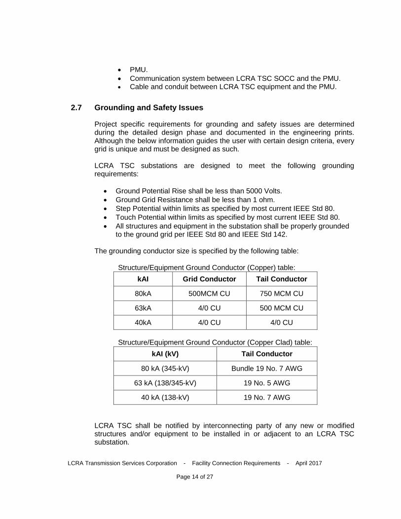
The grounding conductor size is specified by the following table:
Structure/Equipment Ground Conductor (Copper) table:
kAI Grid Conductor Tail Conductor
80kA 500MCM CU 750 MCM CU
63kA 4/0 CU 500 MCM CU
40kA 4/0 CU 4/0 CU
Structure/Equipment Ground Conductor (Copper Clad) table:
kAI (kV) Tail Conductor
80 kA (345-kV) Bundle 19 No. 7 AWG
63 kA (138/345-kV) 19 No. 5 AWG
40 kA (138-kV) 19 No. 7 AWG
LCRA TSC shall be notified by interconnecting party of any new or modified structures and/or equipment to be installed in or adjacent to an LCRA TSC substation.
LCRA Transmission Services Corporation - Facility Connection Requirements - April 2017
Page 15 of 27
If LCRA TSC adds equipment in the facility owner’s substation/facility, LCRA TSC shall coordinate with the facility owner or their agent on grounding and safety issues to ensure grounding meets industry standards.
Transmission and Generation Facility connections to the LCRA TSC transmission system shall meet the most current version of the following industry standard:
• National Electric Code (NEC) • National Electric Safety Code (NESC) • IEEE Std 80 – IEEE Guide for Safety in AC Substation Grounding • IEEE Std 142 – IEEE Recommended Practice for Grounding of Industrial
and Commercial Power Systems
Transmission lines connecting to an LCRA TSC facility are required to have proper over-head shields and adequate structure grounding for at least one mile out of the substation. Transmission line structure grounding, as stated in the Transmission Line Engineering Standards Design document, is defined below:
• 10 ohms maximum grounding resistance at each structure is optimum. • Where 10 ohms is not practical, attempt to obtain 20 ohms maximum
grounding resistance. • Where 20 ohms is not practical, perform an adequate analysis of the
grounding systems and lightning performance for the entire transmission line and determine grounding resistance requirements for individual structures or groups of structures along the entire length of line.
2.8 Insulation and Insulation Coordination
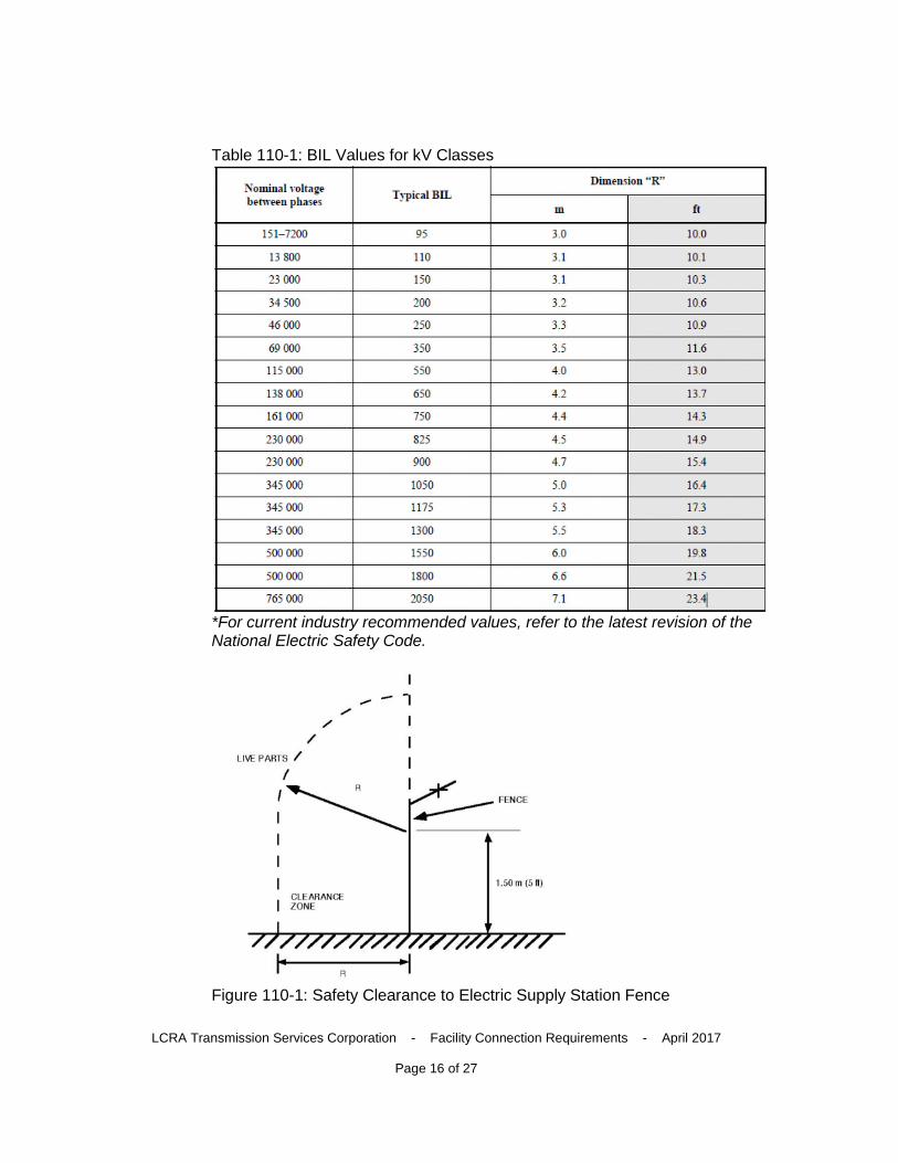
All structures and equipment in the substation shall be properly designed to meet clearances per standards outlined above. The minimum substation Basic Insulation Levels (BIL) required within a LCRA TSC substation are shown below per the National Electrical Safety Code C2-2012, Table 110-1 & Figure 110-1:
LCRA Transmission Services Corporation - Facility Connection Requirements - April 2017
Page 16 of 27
Table 110-1: BIL Values for kV Classes
*For current industry recommended values, refer to the latest revision of the National Electric Safety Code.
Figure 110-1: Safety Clearance to Electric Supply Station Fence
LCRA Transmission Services Corporation - Facility Connection Requirements - April 2017
Page 17 of 27
Surge Arrester and BIL Coordination The arrester rating must be selected such that the maximum continuous power system voltage applied to the arrester is less or equal to the arrester’s continuous voltage capability. An arrester of the minimum practical rating is preferred for its greatest margin of protection of the equipment. A minimum of 15 percent margin between arrester protective level and 83 percent of the equipment basic insulation level (BIL) is recommended.
2.9 Voltage, Reactive Power, and Power Factor Control
Transmission Service Voltages 69, 138, or 345-kV (nominal) Transformation Service Voltages 12.5 or 24.9-kV (nominal)
Operating Voltage Limits (for load serving substations) • Normal Conditions 95-105% • Contingency Conditions 92-105%
Power Factor (ERCOT requirement) • Load 97% • Generator 95% leading and lagging
Generators shall be able to remain online during voltage disturbances up to the time periods and associated voltage levels set forth in ERCOT Requirements for voltage ride-through capability.
ERCOT and/or LCRA TSC will recommend a voltage profile and the point of interconnection for new and existing generators. The voltage profile is reviewed two times each year for interconnected generation. The voltage profile at the point of interconnection for generating facilities shall be established between 0.95 per unit and 1.05 per unit under normal operating conditions and 0.92 per unit and 1.05 per unit under contingency conditions. Generator Operators shall maintain the point of interconnection voltage within 2 percent of the voltage profile in conformance with ERCOT Protocols.
LCRA TSC reviews voltage performance a substations with interconnected loads during the initial interconnection study and through subsequent annual assessments.
2.10 Power Quality Impacts
Voltage Fluctuations and Flicker Voltage fluctuations may be noticeable as visual lighting variations (flicker) and can damage or disrupt the operations of electronic equipment. IEEE Standard 519 provides definitions on limits on acceptable levels of voltage fluctuation. Load or system connections to the LCRA TSC system shall comply with the limits set by
LCRA Transmission Services Corporation - Facility Connection Requirements - April 2017
Page 18 of 27
IEEE 519. If it is determined that the new connection is the source of the fluctuations, the necessary equipment to control the fluctuations to the limits identified in IEEE 519 is the responsibility of the Customer.
Harmonics Harmonics can cause telecommunications interference, increase thermal heating in transformers, disable solid state equipment and create resonant overvoltage. In order to protect equipment from damage, harmonics must be managed and mitigated. The new connection shall not cause voltage and current harmonics on the LCRA TSC system that exceed the limits specified in IEEE Standard 519. Harmonic distortion is defined as the ratio of the root mean square (rms) value of the harmonic to the rms value of the fundamental voltage or current. Single frequency and total harmonic distortion measurements may be conducted at the connection point or other locations in the LCRA TSC system to determine whether the new connection is the source of excessive harmonics. If it is determined the new connection is the source of the harmonic voltage and currents, the necessary equipment to control the harmonics to the limits identified in IEEE 519 is the responsibility of the Customer.
Voltage Transients Measures shall be taken to mitigate switching transients and their impact on surrounding systems.
Phase Unbalance Unbalanced phase voltages and currents can affect protective relay coordination and cause high neutral currents and thermal overloading of transformers. To protect LCRA TSC and Customer equipment, the contribution from the new facilities at the connection point shall not cause a voltage unbalance greater than one percent or a current unbalance greater than five percent. Phase unbalance is the percent deviation of one phase from the average of all three phases.
System problems, such as a blown transformer fuse or open conductor on a transmission system, can result in extended periods of phase unbalance. It is the Customer’s responsibility to protect any of their connected equipment from damage that could result from such an unbalanced condition.
Power Factor Generation entity reactive power must meet the requirements of the ERCOT Generation Interconnection or Change Request Procedure and ERCOT requirements.
2.11 Equipment Ratings
The criteria for determining the required performance related to station equipment is provided below. At ERCOT’s direction and driven by potential congestion, station
LCRA Transmission Services Corporation - Facility Connection Requirements - April 2017
Page 19 of 27
equipment upgrades may be necessary for performance above and beyond what is required in this criteria.
1. During any new transmission line project, all station equipment related to that line shall be designed such that the continuous rating of all station equipment is greater than or equal to the continuous rating of the new line. During any transmission line upgrade project, station equipment related to that line shall be upgraded as necessary such that the continuous rating of all station equipment allows for operating conditions described in 2.
2. Station equipment (circuit breakers, circuit switches, wave traps, jumpers, connectors, current transformers, relays, relay settings, etc.) connected in series with the conductor shall be upgraded (independent of a conductor upgrade) if either of the following two conditions are met:
a. The continuous rating of the station equipment is less than or equal to 50 percent of the continuous rating of the conductor; or
b. The loading through the station equipment during normal or single-contingency conditions is greater than or equal to 80 percent of the continuous rating of the station equipment.
Planned loading on autotransformers during normal, single or multiple contingency conditions shall be limited to 100 percent of the auto-transformer’s maximum megavoltampere (MVA) rating as specified by the manufacturer.
Planned transmission line loading shall be such that NESC line-to-ground clearances will be maintained for all anticipated normal and contingency conditions. Transmission system power flow shall not exceed 100 percent of the conductor thermal rating.
Customers shall make the ratings of their equipment or lines known to LCRA TSC for points of interconnection. The owner of facilities shall make known their Facility Ratings to the operator of their Facilities. Reference NERC FAC-008.
The interconnection shall be preceded by an assessment of the capability of the existing transmission system to support the interconnection. Transmission integration assessment conclusions including the rating required for all facilities required to complete the interconnection shall be presented to LCRA Transmission Engineering staff for the development of detail project scopes and cost estimates
LCRA Transmission Services Corporation - Facility Connection Requirements - April 2017
Page 20 of 27
2.12 Synchronizing of Facilities
Synchronizing requirements shall be stated in the appropriate Interconnection Agreement.
Generation Facilities connecting to LCRA TSC are responsible for synchronization to the LCRA TSC Transmission System. LCRA TSC is not responsible for the design of the Facilities’ synchronization relaying. It is highly recommended that the Facilities’ Owners consult with the equipment manufacturers when setting relays associated with the protection of their equipment.
Synchronizing at transmission tie points shall be determined on a site-specific basis as consideration for ERCOT-approved Black Start plans.
2.13 Maintenance Coordination
Article 6, Operations and Maintenance of Interconnection Facilities, of the SGIA and Article 6, System Operation and Maintenance of the LCRA TSC Interconnection Agreement between TSPs addresses Maintenance Coordination. These requirements are described below:
Maintenance of Interconnection Facilities – Generation: The Parties agree to operate and maintain their systems in accordance with Good Utility Practice, National Electric Safety Code, ERCOT Requirements, PUCT Rules and all applicable laws and regulations. Subject to any necessary ISO approval, each Party shall provide necessary equipment outages to allow the other Party to perform periodic maintenance, repair or replacement of the TIF or GIF as the case may be. Such outages shall be scheduled at mutually agreeable times, unless conditions exist which a Party believes, in accordance with Good Utility Practice, may endanger persons or property. No changes shall be made in the normal operation of the Point of Interconnection without the mutual agreement of the Parties except as otherwise provided herein. All testing of the Plant that affects the operation of the Point of Interconnection shall be coordinated between the TSP, ERCOT, and the Generator and shall be conducted in accordance with regulatory and statutory requirements, including NERC and ERCOT Requirements.
Maintenance of Interconnection Facilities – Transmission: The Parties shall, consistent with maintaining good operating practices, coordinate their operations to maintain continuity of services to their respective customers to the extent practicable. Planned facility maintenance by either Party that will cause a deviation from the normal power and energy flow at a Point of Interconnection shall be scheduled at a mutually agreeable time. No changes shall be made in the normal operation of a Point of Interconnection without the mutual agreement of the Parties. The Parties shall, to the extent necessary to support continuity of operations, coordinate the operation of protective devices on the facilities they operate in the proximity of the Points of Interconnection which might reasonably be expected to
LCRA Transmission Services Corporation - Facility Connection Requirements - April 2017
Page 21 of 27
affect the operation of facilities on the other Party’s system. All testing of the facilities that affects the operation of the Point of Interconnection shall be coordinated between the TSPs and ERCOT and shall be conducted in accordance with regulatory and statutory requirements, including NERC and ERCOT Requirements.
2.14 Operational issues (abnormal frequency and voltages)
Each Party shall, at each Point of Interconnection and at its own risk and expense, design, install, or cause the design and installation, of the transmission or distribution facilities (including all apparatus and necessary protective devices) on its side of the Point of Interconnection, so as to reasonably minimize the likelihood of voltage and frequency abnormalities, originating in the system of one Party, from affecting or impairing the system of the other Party, or other systems to which the system of such Party is interconnected.
Under-frequency load shedding and generator under-frequency relay settings must be maintained for prospective transfers consistent with ERCOT Nodal Operating Guides in order to maintain the dynamic stability of the interconnected system. See Section 2.6 of the ERCOT Nodal Operating Guides requirements for under-frequency relaying.
LCRA TSC shall periodically review its system to determine if under-voltage load shedding is necessary and shall coordinate with affected Parties as necessary.
System operating conditions may dictate limits outside of normal and contingency ratings.
2.15 Inspection Requirements for Existing or New Facilities
To maintain the reliability of the LCRA TSC transmission system, LCRA TSC reserves the right, upon request, to review the interconnecting party’s design schemes, equipment placement and ratings.
To maintain the reliability of the LCRA TSC transmission system, LCRA TSC reserves the right to conduct facility inspections of Generation and Transmission Facilities. The inspection of interconnection facilities is to observe and not to be construed as a formal engineering review of the interconnecting party’s compliance with, among other things, ERCOT Nodal Operating Guides, section 6.2.6, Requirements and Recommendations for ERCOT System Facilities.
Facility inspections shall be coordinated between the respective Project Managers and shall consist of, but not limited to, the following substation design categories:
• Substation/Switchyard
LCRA Transmission Services Corporation - Facility Connection Requirements - April 2017
Page 22 of 27
• Fence • Steel Structures • Concrete Foundations • Grounding • Bus & Fitting • Control House • Substation Equipment • Telecommunications Equipment
Additionally, Section 6.2.5 (3) of the ERCOT Nodal Operating Guides states “The Facility Owner shall periodically test and inspect all components of the protective relay system to assure continued reliability. Identified deficiencies shall be corrected. Documentation demonstrating compliance with the Facility Owner’s maintenance and testing programs shall be supplied to ERCOT or NERC upon their request within 30 days.”
2.16 Communications and procedures during normal and emergency operating conditions
Normal Operations: The Transmission System Operator shall assist neighboring utilities and generation interconnects in implementing all transmission switching functions as necessary, according to associated interconnect agreements, good utility practice, regulator and statutory requirements, and to safely and efficiently operate the transmission bulk system.
The Transmission System Operator shall notify ERCOT and appropriate neighboring utility of any abnormal relaying configuration that may affect reliability.
The interconnecting party’s operation center is expected to fully cooperate with the LCRA TSC Transmission System Operators.
Emergency Operations: The Transmission System Operator shall render available emergency assistance to neighboring utilities and generation interconnects provided the neighboring utility or generation interconnect has completed implementation of its own emergency procedures. These actions by Transmission System Operator shall not, however, violate safety, equipment or regulatory or statutory requirements.
The Transmission System Operator shall not remove any facilities from service that would burden a neighboring utility or generation interconnect. If removal is necessary, the Transmission System Operator shall contact ERCOT and the affected neighboring utility or generation interconnect at the earliest possible time and explain the impact of removing such facilities.
LCRA Transmission Services Corporation - Facility Connection Requirements - April 2017
Page 23 of 27
The Transmission System Operator shall notify ERCOT and appropriate neighboring utility of any abnormal relaying configuration at LCRA TSC owned or operated facilities that may affect reliability.
The interconnecting party’s operation center is expected to fully cooperate with the LCRA TSC Transmission System Operators.
2.17 Provision of Facilities Associated with LCRA TSC Transmission, Transformation, and Metering Services
The provision of facilities by LCRA TSC described below is limited to typical requests for interconnection. Requests that result in other interconnection options shall be evaluated on a case-by-case basis.
Transmission Facilities • For interconnecting a substation (load-serving and/or autotransformer) or a
transmission line to an existing LCRA TSC transmission line, at minimum, LCRA TSC shall provide all series elements on the existing LCRA TSC transmission line and the termination equipment for the interconnecting transmission element(s).
• For interconnecting a transmission element to an existing LCRA TSC substation, at minimum, LCRA TSC shall provide the termination equipment for the new transmission element.
Transformation Facilities• At substations where LCRA TSC owns or will own the property, LCRA TSC
shall provide the transformation facilities (including transformer, transformer protection, voltage regulation, low-voltage bus and associated bus bays with switches, and high-side disconnecting device including switch in front of fuse or circuit switcher).
• If requested by the interconnecting entity, at substations where LCRA TSC does not own or will not own the property, LCRA TSC may provide the transformation facilities if it is cost-effective to LCRA TSC.
• LCRA TSC does not provide low voltage facilities (e.g., low voltage circuit breaker, foundation, jumpers, controls and distribution surge arresters).
Metering Facilities • LCRA TSC shall provide the metering facilities (including CT, PT and meter
panel) where LCRA TSC provides transformation facilities. • If requested by the interconnecting entity, LCRA TSC shall provide the
metering facilities where LCRA TSC does not provide transformation facilities and it is cost-effective to LCRA TSC. If metering CT is internal, transformer owner owns the CT.
• A Metering Service Agreement (MSA) shall be developed and executed.
LCRA Transmission Services Corporation - Facility Connection Requirements - April 2017
Page 24 of 27
Property • LCRA TSC shall provide the substation property (including fence, control
house, ground grid, battery bank, HVAC system, yard lights and is responsible for vegetation management) at substations where LCRA TSC provides transformation facilities.
Facility ownership shall be documented in associated interconnect agreements with eligible interconnecting entities.
An interconnection agreement or other agreement may address any necessary contribution in aid of construction or cost reimbursement language for a specific connection request.
Substation bus arrangements shall be provided by LCRA TSC in accordance with project requirements or as specified by the LCRA TSC Transmission System Planning Criteria.
For load-interconnecting substations: • Where a main-and-transfer bus configuration is installed, the installation may
include a back-up protection device (e.g. fuse) during periods when the transfer bus is providing the service.
• Where a by-pass is used for the interrupting device (e.g. circuit switcher), a back-up relaying scheme shall be provided.
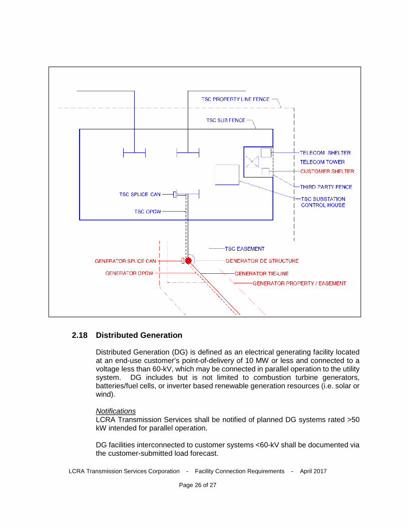
Physical Arrangement: • The transmission customer will own a dead-end (DE) structure outside of the
LCRA TSC property, approximately 30 feet from the property line. • The transmission customer will own property or an easement up to the LCRA
TSC substation property, with language in the IA allowing LCRA TSC to own conductor and OPGW on the customer’s property or easement.
• LCRA TSC will obtain an easement block around the POI structure to allow construction/maintenance crews to access the structure. If direct access from the LCRA TSC substation property is not feasible, LCRA TSC will obtain an access easement to the POI structure.
• The transmission customer will terminate conductor and OPGW at the customer-owned DE structure.
• The transmission customer will own an OPGW splice box on the customer-owned DE structure.
• LCRA TSC will review and approve DE structure height and location, as well as conductor clearances and tensions to ensure these are compatible with substation equipment and A-frames.
• LCRA TSC will own conductor (including jumpers) and OPGW between the transmission customer’s DE structure and TSC A-frame.
• LCRA TSC will splice the transmission customer’s OPGW and the LCRA TSC’s OPGW at the customer-owned DE structure and splice box.
LCRA Transmission Services Corporation - Facility Connection Requirements - April 2017
Page 25 of 27
• LCRA TSC will provide vehicle access to the third party fence and to the TL Easement either on LCRA TSC property or via an off-property access easement.
• Substation control house must be set back by a minimum of 50 feet from substation fence.
• Telecommunications equipment bay(s) shall be as close to the telecom tower as possible within the control house to minimize cable distances.
• Telecommunications towers will be located on substation property such that: o provides 3rd party access; where 3rd party access is required, a
separate telecom shelter will be constructed and telecom shelter and control house will be connected via fiber.
o does not compromise substation physical security requirements. o has no more than 20 feet distance between the telecom shelter and
the telecom tower, and no more than 20 feet distance between the customer shelter and the telecom tower.
o cable routing will be above ground (via ice bridge or other structure). o has an ice bridge for distances greater than 5 feet. o if customer cannot be accommodated in telecommunications shelter;
the customer shelter will be constructed by the customer. o 3rd party fence will be same type of security fence as remainder of
substation fence. o Substation site design will provide drivable access outside of LCRA
TSC Sub Fence to “Third Party Fence” area.
LCRA Transmission Services Corporation - Facility Connection Requirements - April 2017
Page 26 of 27
2.18 Distributed Generation
Distributed Generation (DG) is defined as an electrical generating facility located at an end-use customer’s point-of-delivery of 10 MW or less and connected to a voltage less than 60-kV, which may be connected in parallel operation to the utility system. DG includes but is not limited to combustion turbine generators, batteries/fuel cells, or inverter based renewable generation resources (i.e. solar or wind).
Notifications LCRA Transmission Services shall be notified of planned DG systems rated >50 kW intended for parallel operation.
DG facilities interconnected to customer systems <60-kV shall be documented via the customer-submitted load forecast.
LCRA Transmission Services Corporation - Facility Connection Requirements - April 2017
Page 27 of 27
Assessments A DG impact study may be performed for DG installations rated >50 kW intended for parallel operation.
Metering Facilities Specialized revenue metering, instrument transformers, and communications may be required at the point of common coupling to account for bi-directional energy flows and for revenue settlement purposes. Requirements may vary based on the DG size and application (e.g. Wholesale Storage Load (WSL) or Emergency Response Service (ERS)).
Relaying and Control Depending on the results of a DG impact study, specialized protective relaying may be required to provide reverse-power, under-frequency, under-voltage, transfer tripping, or other protection requirements. Requirements vary based on the DG size and technology.
Reference Documents PUC §25.211. Interconnection of On-Site Distributed Generation (DG) PUC §25.212. Technical Requirements for Interconnection and Parallel Operation of On-Site Distributed Generation