Embed Size (px)
Citation preview

Instruction ManualInstruction Manual
Model LD Series Manual
Interscan Corporation

INTERSCAN CORPORATION
LD SERIES MANUAL
TABLE OF CONTENTS
SECTION TITLE PAGE 1.0 Equipment Description 1 2.0 General Information 3 3.0 Installation & Operating Instructions 8 4.0 Special Instructions 11 5.0 Calibration 12 6.0 General Maintenance 18 7.0 Troubleshooting 20 8.0 Warranty 30 9.0 Parts List 31 10.0 Schematics & Wiring Diagrams 32 11.0 Return Authorization 33 12.0 Index 34
-1-
Equipment Description See Section 4 for Special Instructions
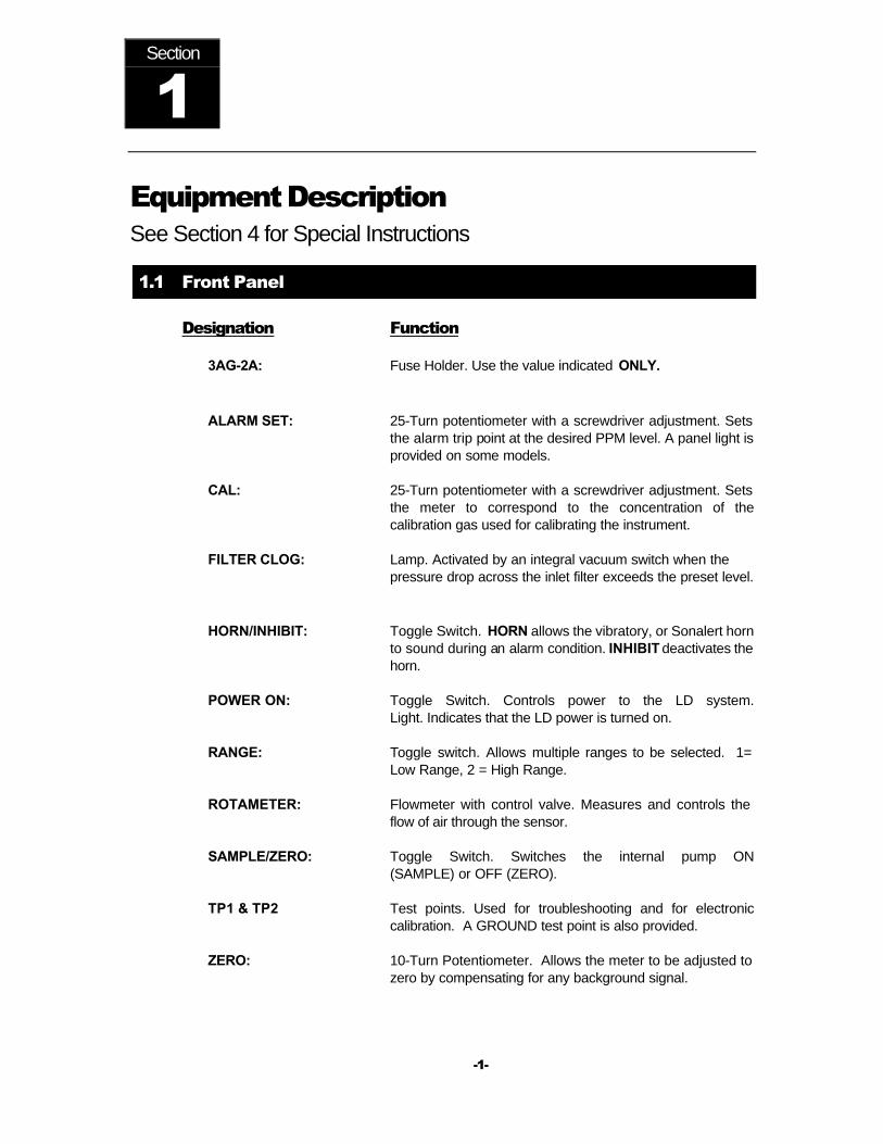
1.1 Front Panel
Designation Function
3AG-2A: Fuse Holder. Use the value indicated ONLY.
ALARM SET: 25-Turn potentiometer with a screwdriver adjustment. Sets
the alarm trip point at the desired PPM level. A panel light is provided on some models.
CAL: 25-Turn potentiometer with a screwdriver adjustment. Sets the meter to correspond to the concentration of the calibration gas used for calibrating the instrument.
FILTER CLOG: Lamp. Activated by an integral vacuum switch when the pressure drop across the inlet filter exceeds the preset level.
HORN/INHIBIT: Toggle Switch. HORN allows the vibratory, or Sonalert horn
to sound during an alarm condition. INHIBIT deactivates the horn.
POWER ON: Toggle Switch. Controls power to the LD system. Light. Indicates that the LD power is turned on.
RANGE: Toggle switch. Allows multiple ranges to be selected. 1= Low Range, 2 = High Range.
ROTAMETER: Flowmeter with control valve. Measures and controls the flow of air through the sensor.
SAMPLE/ZERO: Toggle Switch. Switches the internal pump ON (SAMPLE) or OFF (ZERO).
TP1 & TP2 Test points. Used for troubleshooting and for electronic calibration. A GROUND test point is also provided.
ZERO: 10-Turn Potentiometer. Allows the meter to be adjusted to zero by compensating for any background signal.
Section
1

-2--
1.2 Outside Left Panel
SAMPLE INLET: Unmarked ¼ “ OD compression gas fitting, usually
provided with a filter (see Sec. 2.4), located near the top.
ALARM CONTACTS: Unmarked MS-type mating connector or conduit (Access) hub. Location varies if provided.
RECORDER OUTPUT: Unmarked phone jack with a spring-loaded dust cover. Location varies if provided.
1.3 Outside Top Panel
ALARM LIGHT: Unmarked mounting location for the rotating beacon-ray
light. ½” conduit hub. Located near the left side if provided.
ALARM HORN: Unmarked mounting location for the vibratory horn. ½ conduit hub. Located near the right side, if provided.
1.4 Outside Right Panel
EXHAUST: ¼" OD compression gas fitting.
BYPASS: ¼" OD compression gas fitting.
ALARM HORN: Sonalert horn used on ETO monitors, or for POWER OFF alarm. (see Section 2.5.5)
AC LINE POWER: Power cord or optional conduit hub.
NOTE: Systems equipped with unusual features not described in this section may also be provided with certain components located on the exterior of the enclosure. Such special features and components are described in Section 4.0.
-3--
General Information See Section 4 for Special Instructions
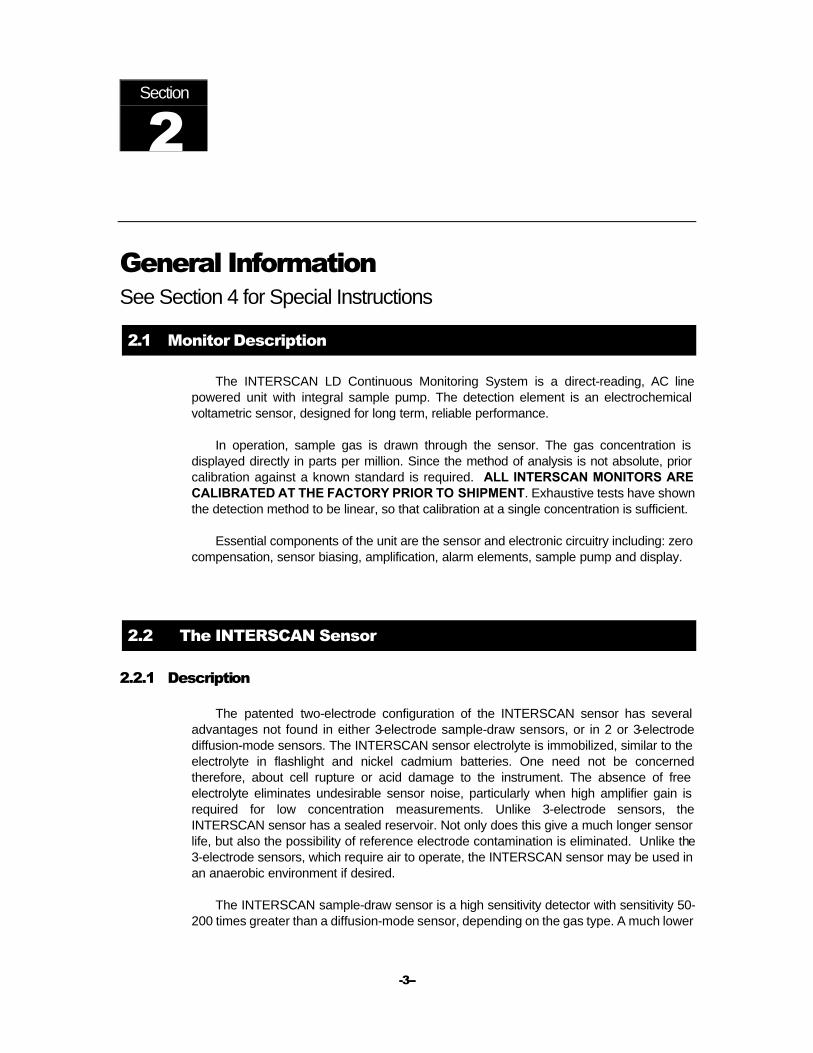
2.1 Monitor Description
The INTERSCAN LD Continuous Monitoring System is a direct-reading, AC line powered unit with integral sample pump. The detection element is an electrochemical voltametric sensor, designed for long term, reliable performance.
In operation, sample gas is drawn through the sensor. The gas concentration is displayed directly in parts per million. Since the method of analysis is not absolute, prior calibration against a known standard is required. ALL INTERSCAN MONITORS ARE CALIBRATED AT THE FACTORY PRIOR TO SHIPMENT. Exhaustive tests have shown the detection method to be linear, so that calibration at a single concentration is sufficient.
Essential components of the unit are the sensor and electronic circuitry including: zero compensation, sensor biasing, amplification, alarm elements, sample pump and display.
2.2 The INTERSCAN Sensor
2.2.1 Description
The patented two-electrode configuration of the INTERSCAN sensor has several advantages not found in either 3-electrode sample-draw sensors, or in 2 or 3-electrode diffusion-mode sensors. The INTERSCAN sensor electrolyte is immobilized, similar to the electrolyte in flashlight and nickel cadmium batteries. One need not be concerned therefore, about cell rupture or acid damage to the instrument. The absence of free electrolyte eliminates undesirable sensor noise, particularly when high amplifier gain is required for low concentration measurements. Unlike 3-electrode sensors, the INTERSCAN sensor has a sealed reservoir. Not only does this give a much longer sensor life, but also the possibility of reference electrode contamination is eliminated. Unlike the 3-electrode sensors, which require air to operate, the INTERSCAN sensor may be used in an anaerobic environment if desired.
The INTERSCAN sample-draw sensor is a high sensitivity detector with sensitivity 50-200 times greater than a diffusion-mode sensor, depending on the gas type. A much lower
Section
2

-4--
minimum detect-ability is possible...an important requirement for measuring gas that has a low TLV.
2.2.2 Principle of Operation
The INTERSCAN voltametric sensor (U. S. Patent Number 4,017,373) is an electrochemical gas detector operating under diffusion-controlled conditions.
Gas molecules from the sample are adsorbed on an electro catalytic sensing electrode, after passing through a diffusion medium, and are electrochemically reacted at an appropriate sensing elec trode potential. This reaction generates an electric current directly proportional to the gas concentration. This current is converted to a voltage for meter or recorder readout.
The diffusion-limited current, ilim, is directly proportional to the gas concentration according to the simplified equation:
ilim =
Where ilim is the limiting diffusion current in amps, F is the Faraday constant (96,500 coulombs), A is the reaction interfacial area in cm2, n is the number of electrons per mole reactant, ≈≈ is the diffusion path length, C is the gas concentration moles/cm3), and D is the gas diffusion constant, representing the product of the permeability and solubility coefficients of the gas in the diffusion medium.
An external voltage bias maintains a constant potential on the sensing electrode, relative to a non-polarizable reference counter electrode in the 2-electrode INTERSCAN sensor. "Nonpolarizable" means that the counter electrode can sustain a current flow without suffering a change in potential. Thus, the counter electrode acts also as a reference electrode, thereby voiding the need for a third electrode and a feedback circuit, as would be required for sensors using a polarizable air counter electrode.
2.3 Electronics 2.3.1 General
The LD-Series Continuous Monitoring System electronic circuitry consists of the following elements: A reference supply, an amplifier, a buffer, and a comparator with relay driver.
2.3.2 Reference Supply (Bias Voltage)
The reference supply is a voltage follower, which inputs a stable voltage generator across a resistance divider. In operation, an infinitesimal current drains from the cell. The output provides very low source impedance to the sensor.
nFADC ≈≈
-5--
2.3.3 Amplifier (Zero Compensation)
Since the sensor is a current source with virtually zero resistance, the amplifier is operated in the current mode. Feedback from output to input determines stage gain. Range changing incorporates parallel resistor selected to produce an error of less than ±1% of full scale. Sensor and amplifier offset currents are cancelled by summing an error current through the ZERO potentiometer.
2.3.4 Buffer (0-100 mV Output) The amplifier output is divided by the CAL potentiometer, which drives the buffer. The buffer output drives the meter, and supplies the necessary voltage to the 0-100 mV recorder terminals, the 4-20 mA transmitter and the comparator input.
2.3.5 Comparator
The comparator is a high gain operational amplifier, the reference level of which is set by the ALARM SET control. The analog input from the buffer provides the trip level, driving a transistor, which in turn activates the alarm relay.
2.4 Pneumatics
2.4.1 General
In this discussion, we are primarily concerned with the following elements: The inlet filter, the internal tubing, the rotameter, the diaphragm pump, the tube fittings, the optional vacuum switch and aspirator.
2.4.2 Inlet Filter
Three different configurations are commonly supplied, depending upon application: The sealed canister type (Koby), the coalescer/ micro fiberglass type (Balston) and the Swinnex/Teflon element type (Millipore). All the filters give 99.9% removal of particles 0.5 micron and larger.
The LD-20, ETO Monitor uses the Millipore Swinnex/Teflon element type filter. It is the most inert of the three. (see Section 6.2)
2.4.2.1 Sealed Canister Type (Koby)
This filter is provided (unless otherwise specified) on all carbon monoxide (LD-14) monitoring systems. The filtration medium consists of several layers of gauze and finely

-6--
divided activated charcoal. The canister body itself is made from zinc-plated cold rolled steel, and is provided with ¼ “ NPT brass fittings. This filter is, by far, the most rugged and rigorous of the three, but cannot be used with any corrosive gases (SO2, NO2, Cl2, H2S) for two reasons: Charcoal absorbs those gases, and those gases would attack and eventually destroy the canister body.
2.4.2.2 Coalescer/Micro fiber Glass Type (Balston)
This filter may be used for all the other gases, and should be used if sample condensation is a potential problem. The housing is polycarbonate, which is corrosion-resistant.
The filter element may retain water under certain climatic conditions, which would be unacceptable for SO2 monitoring. Generally, a trade-off must be made between the necessity for water removal from the sample, and the required inertness of the filter medium.
2.4.2.3 Swinnex/Teflon Element Type (Millipore)
This filter may be used for all the gases, and is the most inert of the three. On the other hand, its element is the least rugged.
2.4.3 Sample Tubing
Either Bev-A-Line IV, polyethylene, type TFE Teflon or stainless steel tubing is recommended. Other materials, such as vinyl, copper or nylon, are not recommended.
2.4.4 Rotameter
The rotameter is mounted upstream of the pump, and serves primarily to restrain the pump to provide the low flow rate (0.5 liter/minute) needed by the sensor. Additionally, the rotameter indicates that the sample is indeed being drawn through the sensor. The meter body is constructed of acrylic plastic, the float is black glass and the metering valve is type 316 stainless steel. Accuracy is rated at ±10% of full scale.
2.4.5 Diaphragm Pump
The LD Systems employ a heavy -duty diaphragm pump, which is located downstream of the sensor. Even though all gas-contacting parts within the pump are of Teflon or Viton, the downstream location ensures that sample is not lost or contaminated at the pump head.

-7--
2.4.6 Tube Fittings
Polypropylene compression-type tube fittings are used through out. Finger tightening is adequate for these fittings, as the use of a wrench can shear them or strip the threads. These fittings were chosen primarily for their inertness. The pneumatic fittings can loosen over a period of time, and they should be checked periodically.
2.4.7 Vacuum Switch (Optional)
The vacuum switch is located upstream of the pump and is customer adjustable 1.20 - 30.0 inHg (-4.06 to -101.6 kPa). This switch activates the FILTER CLOG lamp. A completely clogged filter would cause the pump to pull its full vacuum across the sensor. Although short -term leak tests are performed with the system's inlet plugged, and although the sensors themselves are bell jar tested at 16 inHg (-54.2 kPa)† repeated and prolonged exposure of the sensor to excessive vacuum can be detrimental.
† The sample pump itself would never achieve this vacuum across the sensor, due to the bypass.
2.4.8 Aspirator (optional)
Provided in lieu of the diaphragm pump, the Teflon body aspirator is operated with plant air; although in the instrument air is used, the air supply is often split for purge of the enclosure, as well.
Since the materials of construction are quite inert (a Kel-F jet is used), the aspirator finds its greatest application in systems designed to monitor highly corrosive gases. The air requirement, however, often forces a trade-off back to the diaphragm pump.
PUMP SPECIFICATIONS AS FOLLOWS:
Maximum Vacuum: 16.0 inHg (-54.2 kPa)
Maximum Pressure: 6.0 lb/in2g (41.4 kPa)
Free Output: 4.5 l/min
2.4.9 Bypass
To eliminate excessive pressure drop across the sensor when the INLET becomes restricted, an additional inlet source has been added to the pump. To ensure that the pump does not only pull from the bypass (path of least resistance), a restriction (plastic orifice) has been installed in the bypass tubing. This tubing originates at an enclosure bulkhead next to the exhaust bulkhead. In applications that expose the monitor to heavy particulate, a filter should be installed to the bypass fitting to prevent the bypass orifice from becoming clogged.

-8--
Installation & Operation See Section 4 for Special Instructions
3.1 INSTALLATION
3.1.1 Inspection
Open the box(es) and inspect for damage immediately upon receipt. Examine the Contents List and ensure all items that were shipped, have been received. Contact INTERSCAN and report any damaged or missing items immediately. Items discovered “missing” more than 30 days after shipping will not be replaced at no charge.
3.1.2 Mounting
Locate the mounting hole in each corner of the LD Monitor. Use four 5/16” diameter bolts to mount the LD in the desired location. The mounting holes are separated 16 -¾” apart horizontally and 12" apart vertically.
3.1.3 Rotating Beacon-Ray Light or Strobe (if provided)
Feed the light's wires through the left hub assembly located on top of the monitor. Thread the light into the hub and tighten. Connect the two twisted white wires from TB1 to the light assembly.
3.1.4 Vibratory Horn (if provided)
Feed the horn's wires through the right hub assembly located on top of the monitor. Thread the horn into the hub and tighten. Connect the two twisted black wires from TB1 to the horn assembly.
3.1.5 Sonalert Horn (if provided)
The Sonalert horn is installed by INTERSCAN prior to shipping and requires no additional adjustments upon receipt. It is a black plastic disk mounted on the right side of the top of the monitor.
Section
3

-9--
3.1.6 Heater Thermostat (if provided) Open the enclosure cover. Thermostat and heater are located below the lower panel
support. Adjust the thermostat to a setting about 10°F below the normally expected ambient temperature. If provided, the thermostat is factory set to approximately 60°F.
3.1.7 Power Off Alarm (if provided)
The LD Monitor is shipped with the Power Off Alarm switched to OFF. After AC power has been connected, switch to P.O. Alarm. The Sonalert alarm is powered by a 9-volt alkaline battery. The alarm should be checked every few months to verify the battery condition supplies an adequate alarm.
3.1.8 Initial Start-Up Allow the monitor to stabilize for 12 to 24 hours with Power ON before attempting to operate. Ignore any alarms or high readings during this time.
3.2 Operation
Your INTERSCAN monitor has already been calibrated at the Factory, and is ready to use.
3.2.1 Zeroing
Adjust the ZERO control to read zero on the meter. Normally the SAMPLE/ZERO switch should be in the ZERO position; however, for low range units (2 ppm or less F.S.), and for all Ethylene Oxide, Formaldehyde and Hydrazine models, zero the monitor with the pump on (SAMPLE selected). Attach an activated filter or zero air to the inlet to assure an accurate zero adjustment. (see Section 4.0 for Special Instructions).
3.2.2 Sampling
Set SAMPLE/ZERO switch SAMPLE. If necessary, you may switch to a higher range on multi-range monitors. When the pump is switched off, allow meter to return to zero on its own. In the case of low range models or for Formaldehyde and Hydrazine models, a true zero requires the pump to be on, and a charcoal filter to be attached.
3.2.3 Setting the Alarms
Normally, the alarm is set at the factory at 50% of scale. The alarm can be re-set to any desired level by following a simple procedure.
-10--
1. Using the ZERO control, advance the meter to the desired alarm set point. Single high range units may require high ppm gas to set alarm.
2. Adjust the ALARM SET control until the corresponding alarm light or horn turns on.
3. Adjust the ZERO control slightly counterclockwise until the alarm turns off. Slowly adjust the zero control clockwise until the alarm sounds. Re-adjust the ALARM SET control if necessary.
NOTE:
The alarm set point is attenuated via the RANGE switch to the same meter position (% of full scale), rather than the same numerical value.
e.g. In a 0-100/0-500 ppm dual range unit, a 50 ppm set point on the low range would become a 250 ppm set point when switched to the high range.

-11--
Special Instructions
Not Applicable for This Instrument
Section
4
-12--
Calibration See Section 4 for Special Instructions
5.1 Introduction
It is not necessary to calibrate the monitor when received from the Factory, or from an INTERSCAN distributor. All INTERSCAN monitors are calibrated at the Factory prior to shipment. Unless the CAL adjust is inadvertently changed, there is no need to calibrate the monitor until it has seen considerable usage.
There is no easy answer as to when a monitor should be calibrated. This is strictly a function of the application. INTERSCAN monitors can probably go for months without recalibration. Again, it is a function of usage. The need for calibration is to compensate for any possible decrease in sensor sensitivity. The primary cause of sensitivity decrease is excessive loss of water by evaporation. A secondary cause may be by contamination from unknown sources. H2S sensors show an additional decrease in sensitivity due to internal sulfur formation, the rate of which depends on the gas concentration.
A good recommendation is to calibrate the monitor every 3 months. A record should be kept of the ppm concentration used to calibrate, as well as the ppm concentration displayed by the monitor prior to adjusting the CAL adjust. If the difference between these two values is unacceptably high (>10% for example), the monitor should be calibrated more frequently. If the difference is well within an acceptable tolerance (<2% for example), calibrations can be performed less frequently.
The instrument is calibrated by introducing a known concentration of gas and adjusting the CAL control to the proper ppm level. This fact requires that the analyzed ppm of the gas be accurate. The sources of calibration gas standards include commercially available gas mixtures diluted with air or nitrogen in cylinders; permeation devices; and user dilution of concentrated or high ppm cylinder gases.
Unless cylinder gases are available, most users are either not properly equipped to perform acceptable calibrations, or do not want to be bothered with the procedures necessary to attain an accurate calibration. Added to this is the uncertainty of the labeled ppm value of cylinder gases due to instability over a time period. The reliability varies among calibration gas manufacturers.
For the above reasons, INTERSCAN offers their "Electronic Calibration Service" (ECS), which permits the user to calibrate their monitors without the use of gas. Calibration is accomplished by quick and simple adjustments of the ZERO and CAL controls using a digital voltmeter. See the attached information sheet on ECS.
Calibration can be particularly difficult in the case of Chlorine and HCl gases which are easily chemisorbed, even by chemically inert tubing. HCl calibration is more complex
Section
5

-13--
because of the high moisture solubility. ECS is especially recommended for Chlorine and HCl monitors for time saving, trouble-free, and reliable calibration. ECS is also strongly recommended for Formaldehyde monitors. Formaldehyde permeation tubes (polyoxymethylene) require a calibrator with a controlled temperature of 90°C.
5.2 Calibration Gas Standards
Low part-per-million gas mixtures (in air or nitrogen) are available, with few exceptions, in pressurized cylinders. The major concern in using commercially-available, low ppm mixes of such active gases as SO2, H2S, NO, NO2, Cl2, etc., is their reliability. The analysis shown on the label is applicable only at the time the analysis was performed. Concentration stability with time varies widely as a function of the gas mix, its container and the manufacturer. Moreover, changes in concentration are not slight. Typically, the actual concentration of an unstable gas may be one-tenth of its labeled value. Of particular concern is the stability of H2S and SO2 mixtures. Some commercially available mixtures are unstable, in some cases, in less than a month. INTERSCAN should be consulted for recommendations on commercially available gas mixtures.
An alternative source of calibration gas is the use of permeation devices containing the liquefied gas under pressure. Permeation of the gas in nanogram per-minute rates, permits the generation of a desired concentration in an air or nitrogen carrier. Varying the temperature, flow rate and emission rate characteristics gives a fairly wide range of gas concentrations. Many gases, including H2S, SO2, NO2, CL2, HCl, HCN and Hydrazine (INTERSCAN analyzers are available for all these gases), are ideally suitable to the permeation device technique. With the exception of sophisticated laboratory dilution techniques, CL2, HCl and Hydrazine (or MMH and UDMH) permeation devices should be used for these gases.
The Teflon tube O’Keefe type of permeation device for H2S requires frequent calibration or independent analytical confirmation, due to a changing permeability caused by sulfur deposition in the walls of the tube. These ARE NOT recommended.
An excellent source of calibration gas is the gas syringe dilution of high ppm (several hundred) gas mixtures, or 100% gas. While this is a reliable and accurate method, it is not convenient for most field applications.
5.3 Sample Bag Calibration
Whatever the source of calibration gas, the recommended method is to collect the gas in the proper sample bag, which is then attached to the analyzer. The calibration gas is drawn through the sensor by the sample pump. An exception to the use of a sample bag is for those gases that are reactive with, or chemisorbed by the bag itself (e.g. Chlorine or Hydrazine. see Section 5.8). Teflon or "Tedlar" bags are suitable for H2S, SO2, NO and NO2. Several bag materials are suitable for CO. Contact the Factory for recommendations.
-14--
The sample bag method is the factory -recommended method. Since an internal pump is used, the same flow rate conditions during the sample and the calibrate modes are assured, eliminating errors due to flow rate differences. For most applications, using a bag is the simplest procedure. A regulated pressurized cylinder fitted with a tee-manifold and unrestricted vent is a good procedure, as long as the flow rate of the gas exceeds that of the sample pump.
5.4 Permeation Devices
The use of a permeation device is prescribed as the preferred method for calibrating most instruments, excluding the CO and NO monitors. In addition, it is the simplest method to use, and probably the most accurate. The ppm concentration varies directly with the permeation rate, and inversely with the flow rate of the carrier gas. The permeation rate is a logarithmic function of temperature in degrees Celsius. (see Section 5.7)
5.5 Auxiliary Equipment
Besides the permeation device, an accurate low flow rotameter, cylinder of zero air or nitrogen, and a thermometer are required. A pump may be used, as an alternative to zero air or nitrogen. Incoming air should be scrubbed for possible interferences. In all cases, only Teflon, Bev-A-Line IV or polypropylene tubing should be used downstream of the permeation device, and preferably should be as short as possible. Tygon or rubber tubing should NEVER BE USED.
5.6 Calibrators
Several calibrators utilizing permeation tubes are available on the market. These range in complexity and price, and are found in both fixed location and portable models. Because some of these may be more sophisticated than required for many monitoring applications, the customer should consult the factory.
NOTE: Refer to Section 4.0 for important information relative to calibrators for hydrazine.
5.7 Permeation Rate And PPM Calculation
Permeation rate information is included with the permeation device by the manufacturer, specified for some temperature. The rate at other temperatures is calculated from:
log P = log Pm ± A (rrt°C)

-15--
24.46 Mol.Wt.
Where Pm is the given permeation rate in ng/min. and A, a constant, depending on the permeation device. This is either given direct by the permeation device manufacturer, or is calculated as the slope of the above equation, from known permeation rates at two temperatures. Some manufacturers include the log P- temperature chart, from which the permeation rate can be read directly.
The gas concentration is calculated from: ppm =
Where K is and F is the carrier gas flow rate, in ml/min, through the
permeation device.
5.8 Chemisorbable Gases
(See Section 4.0 for Special Instructions) Chemisorbable and moisture soluble gases, such as Chlorine, HCl and Hydrazine require that the carrier gas used with the permeation device be totally dry. This requires an efficient drying agent upstream to the U-tube containing the vial.
Even so, under very humid conditions, the drying agent is rapidly saturated, so only dry zero air or nitrogen in cylinders should be used. To emphasize the importance of this, a loss of 73% of Chlorine has been observed under high humidity conditions (by conversion to HCl and HClO). An even greater loss has been observed in the case of Hydrogen chloride. This is aggravated by the restriction to low ppm values, due to the low permeation rates of the available HCl permeation devices. With the user being unaware of these losses, not only is the instrument grossly out of calibration, but also its over-calibrated condition results in excessive instability.
Such gases require the use of a TEE or manifold procedure of calibration. Dried and scrubbed air or nitrogen carrier gas is passed at a known and constant flow rate through a chamber containing the permeation tube. The chamber effluent is passed into a TEE manifold with unrestricted vent at its opposite end. The side arm of the TEE manifold is connected to the instrument inlet. This connecting tube, and that linking the permeation tube chamber with the TEE manifold, as well as the TEE manifold itself, must be polypropylene or Teflon. The tubing should be as short as possible.
The system is working properly when no gas flows into the analyzer with the sample pump off. After allowing sufficient time for the permeation tube to equilibrate (under temperature and flow conditions), the sample pump is switched on drawing the calibration gas through the sensor. The flow rate of the carrier gas should exceed that of the sample pump in the analyzer, to avoid dilution from the vent.
Where good temperature control, or elevated bath temperature (in excess of ambient) are required, the flow rate through the permeation tube should be restricted to 100 ml/min, and diluted with room air to give a total flow rate in excess of the sample pump. Gas concentration is calculated using the total combined flow rates.
Chemisorption by the walls of the connecting tube, and by the filter itself, is a time phenomenon, decreasing gradually over a half-hour period, giving the effect of slow sensor response. True sensor response time requires preconditioning of the connecting tube by allowing the Chlorine or other chemisorbable gases to be drawn through the
P x K F

-16--
tubing for some time prior to attachment to the analyzer. This is particularly important for extended life permeation tubes that generate low ppm levels. For optimum results, such tubes should not be less than 3 cm of active length. These should last more than 8 months with refrigeration. This requires bypassing the sensor during the pre-conditioning. Because of degassing, pre-conditioning is not permanent. This chemisorption effect is not serious, because sensor response to changes in gas concentration is always rapid, even during the initial adsorption period.
5.9 Permeation Tube Manufacturers
With the exception of HCHO and Hydrazine gases, most standard permeation devices can be obtained from Vici Metronics (Santa Clara, California), Analytical Instruments Development (Avondale, Pennsylvania), and Kin-Tek (Texas City, Texas). The only recommended permeation device for HCl monitors is Vici Metronics’ HCl wafer. For Hydrazine (or MMH and UDMH), and Formaldehyde, the factory recommends only the 10 cm Kin-Tek permeation tube.
5.10 Calibration Procedure (See Section 4.0 for Special Instructions)
Select the range (optional) suitable for the concentration of the span gas. (Calibration in one range sets the calibration for all ranges).
With pump off, zero the analyzer with the ZERO control. If necessary, allow a few moments to achieve a stable setting.
For all gases, except Chlorine or other chemisorbable types, fill the sample bag with calibration gas, and attach it to the external inlet fitting. This is best done by attaching a short length (2 inch/51 mm) of ¼ inch/6.4 mm O.D. flexible tubing to the sample bag nipple, then attaching the tubing to a short length of rigid tubing contained within a gas fitting nut securely fastened to the inlet fittings.
For Chlorine and other chemisorbable gases, refer to Section 5.8. The precision rotameter should be set at a flow rate higher than that of the sample rotameter. Allow several hours (preferably overnight) for the permeation tube to equilibrate, before attaching the connecting tube to the inlet fitting. If possible, it is desirable to have a second pump drawing the gas from the TEE manifold during this time, for the purpose of pre-conditioning the connecting tube. After equilibration, attach the connecting tube to the external inlet. (see Section 5.7 for method of calculating the ppm concentration of the gas)
Switch on the pump. Adjust the sample rotameter to 0.5 liter/minute. This is the recommended flow rate, although no accuracy is forfeited if other flow rates are chosen, as long as the sample measurements are made at the same flow rate. Allow the meter to stabilize, and by using the CAL control, set the meter to indicate the span gas concentration. Check the zero and span settings, and re-adjust if required. The instrument is now set up for operation.
-17--
5.11 Electronic Calibration Service
The factory recommended procedure for calibrating all INTERSCAN instruments, involves the use of span gas or a permeation device. Besides being essential for calibration, having a known certified gas standard on hand allows the user to test the instrument at any time to determine that it “really works”.
However, there will be times and circumstances in which calibration using span gas or permeation devices is inconvenient. For this reason, INTERSCAN has developed the Electronic Calibration Service (ECS).
A certified spare sensor is kept on hand, to be put into the instrument, while the presently used sensor is sent back to the factory for re-certification. The ECS certification, illustrated on the last page of this section, details zero and span adjustments that are to be made on the instrument, to set it up with the specified newly certified sensor.
As indicated on the certification sheet, the ECS program verifies sensor sensitivity only. It does not certify the instrument as a whole. Most importantly, the ECS program is not a substitute for basic instrument maintenance, nor does it check for malfunction of the instrument components.

-18--
General Maintenance See Section 4 for Special Instructions
6.1 Pump Fan Filter (if provided)
The filter material should be examined on a scheduled basis to prevent clogging of the fan inlet. Frequency of examination and replacement depends on the operating environment, and must be determined by the user.
6.2 Particulate Filter
This filter removes particulate matter from the sample stream. Particulate filters should be checked at least once every 3 months. The filter should be changed if it is dirty, or frequent adjustment to keep the flow rate above 0.4 liter/minute is necessary. Periodic replacement on a field-determined time interval (for your particular installation) is the best approach. On those systems provided with FILTER CLOG indication, filter condition is continuously monitored. If FILTER CLOG indication is not provided, an observable lower flow rate would indicate a loaded filter.
6.3 Chemical Scrubbers (if provided) Certain LD systems are equipped with charcoal scrubbers (provided as cartridges or other in-line housings). Charcoal removes many gases (including SO2, H2S and NO2), and has a tremendous adsorption capacity. The charcoal is best replaced on a regular time interval (i.e. every 6 months), but can be tested by passing various "challenge" gases through the system.
6.3.1 #158 Scrubbers
Certain LD systems are equipped with #158 scrubbers, which remove acid gases such as SO2, H2S, NO and NO2. From its original violet color, the scrubber changes to a
Section
6

-19--
light brown then to a darker brown, which later deepens to almost black. Even if all the pellets show the brown-black exterior, the scrubber may still retain high efficiency.
Infrequent inspection requires the removal of a few pellets from a thoroughly mixed lot, breaking them open and examining their inner cores. If only one of these retain the violet core, the scrubber is only 33% efficient and should be replaced.
(Some filter configurations combine the chemical scrubber and particulate filtration in one package, as the Koby, described in Section 2.4.2.1)
6.4 Sensor Maintenance Sensors in fixed monitors under continuous operation lose water by evaporation. Optimum performance requires that this water be replaced periodically. This is done by injecting distilled or deionized water into the sensor via the red plug, using the plastic syringe provided. DO NOT USE STERILE WATER!
6.4.1 Water Injection
The amount of water to be added will obviously depend on the humidity and temperature of the operating environment. A suggestion is to inject 20 - 30 ml. every 6 weeks. The sensor can be refilled without being removed from most monitors, but power should be switched OFF, and care taken not to drip water onto any of the electronic circuitry.
The amount of water needed for normal operation of the sensor is not critical for most sensors, but it is advisable not to exceed a maximum weight loss of more than 50 grams. For that reason, it is recommended that the sensor be weighed every 3 months. This is done by removing the sensor from the monitor and comparing the current weight of the sensor with its original weight (in grams) shown as the 3-digit figure on the bottom of the sensor.
To do this, open the right-hand control panel. Disconnect the electrical connections to the sensor. Unscrew the gas fitting nuts. Unscrew the 4 mounting screws in the sensor base. Set aside the 4 screws. Slide the sensor up to remove.
NOTE: DO NOT REMOVE ANYTHING ELSE FROM THE SENSOR!
Restore the original sensor weight by injecting an equivalent cc of distilled or deionized water (10g. weight loss means add 10cc of water). DO NOT OVERFILL. Replace the sensor. Assure that all electrical and pneumatic fittings are secure. The sensor should be allowed to stabilize for several hours with the POWER ON.
-20--
Troubleshooting See Section 4 for Special Instructions
7.1 Introduction
The most likely malfunctions that may occur with the LD or multi-point monitoring systems are mechanical (including excessive pressure or vacuum on the sensor, or loose connections due to vibration), and electronic (less likely, amplifier or power supply failure). Excessive pressure or vacuum on the sensor is to be avoided, as this may force electrolyte out of the sensor into the rotameter, even though the electrolyte in the Interscan sensor is in a bound state. (see Section 7.2 for more details)
Sensor failure should not be assumed as the cause of instrument malfunction. There is no question that with proper maintenance, the sensor should last well in excess of the warranty period. Inability to zero the meter is not an indication of sensor malfunction. The ability to zero the meter by disconnecting the sensor, is also not indicative of sensor malfunction, but only reflects a disturbance of the sensor due to other malfunctions.
7.2 Liquid In Rotameter And Pump
This is a result of excessive pressure or vacuum on the sensor, brought about by any of several reasons discussed below. Directions should be followed closely to avoid this problem, or to prevent its recurrence. If liquid is observed in the rotameter, the sensor should be returned for inspection.
7.2.1 Excessive Pressure on Sensor
This is generally caused by calibrating the instrument from a calibration gas cylinder without first opening the rotameter valve and disconnecting the upper rotameter fitting. With the rotameter and/or pump dead headed, excessive pressure is built up in the sensor, which results in liquid being forced into the rotameter (when the valve is opened), or damage to the sensor and other instrument parts, should the sensor rupture. Since it is necessary to reopen the instrument and reconnect the pump to the rotameter following calibration, the recommended method of calibration is to use the pump and a sample bag. This avoids the necessity of disconnecting and reconnecting the rotameter fitting. If calibrating or sampling from a self-pressurized source, a sample bag or tee fitting must be used to deliver calibration gas to the monitor.
Section
7

-21--
7.2.2 Excessive Vacuum on Sensor
Blockage of gas flow upstream from sensor will create a vacuum on outlet side of sensor, resulting in electrolyte being sucked into the rotameter and possibly the pump. Blockage results from particulate accumulation in the filter or sensor inlet. Sensor blockage will usually occur within the interior of the sensor manifold, and is reachable.
To confirm a filter clog, note rotameter flow indication before and after disconnecting inlet gas fitting on sensor. If filter clog is not indicated, disconnect sensor outlet (PLEASE NOTE: A normal pressure drop exists across sensor, so flow may be slightly faster even though no sensor blockage exists). A filter clog indicator is an available option, and is recommended in high particulate applications.
Overfilling the Sensor even in the absence of excessive pressure or vacuum, liquid may appear in the rotameter. This is due to overfilling the sensor during normal maintenance. Overfilling occurs when the optimum ratio of liquid to absorbent matrix is exceeded.
7.3 Instrument Won't Zero
When the power is turned on, the sensor is subjected to its normal bias voltage. This causes a temporarily high background current, which may initially pin the meter. The instrument can normally be zeroed within minutes, although a half-hour should be allowed to achieve stability.
If it is not possible to zero the instrument after several hours, the most likely cause is failure of the ±15VDC power supply, or the band gap reference CR1 on the amplifier circuit board. If the meter can be zeroed by disconnecting the sensor, this is not an indication of sensor failure. In-ability to zero the instrument with the sensor connected is due to change in the bias voltage on the sensor, resulting in a high background current.
The meter will pin up-scale on CO, H2S, SO2, NO and Hydrazine monitors and downscale on the NO2 and Cl2 monitors. Correction of the problem is to replace the power supply or the CR1 element, and to allow the sensor to re-stabilize. The meter will pin in the opposite direction until re-stabilization has occurred.
7.4 Correction Of Instrument Inability To Zero Refer to Section 7.6.1 and 7.6.3. If the TP1 reading is far different from that shown for
the corresponding model, the most likely fault is that of the ±15VDC power supply or the band gap reference CR1 on the amplifier circuit board. Check out the ±15VDC power supply. (see Section 7.6.2) If the power supply is good, replace CR1.
-22--
7.5 Instrument Will Not Respond To Gas, Or Instrument Still Won't Zero After Correction Of Section 7.4.
Check if CR1 is correctly installed with proper polarity.
Check if sensor banana plug (Blue-White wire) is in sensor jack.
Check if blue wire with lug is securely attached to sensor clamp, and clamp screw is tight.
Check if amplifier circuit board is securely attached to rear panel (use 3/8“ nut driver or socket wrench to tighten nuts securing circuit board).
Check if circuit board connector is securely attached to circuit board (pushed down tight).
With instrument switched on, momentarily touch banana plug to sensor clamp. If circuit board and connector are secure, meter will kick. If no meter response, amplifiers U2 or U3 may be defective.
7.6 DC Voltmeter (VM) Measurements (optional)
7.6.1 Introduction The analyzer panel meter itself serves as readout for most malfunction symptoms. If desired, however, simple voltage measurements may be made to confirm a diagnosis or isolate the origin of a malfunction. In addition, other useful measurements may be made, including specific sensor output, sensor background current and calibration gas check. A digital VM is preferred, although a standard multi-meter with 1.0, 2.5 and 15V scales or greater is adequate.
In all measurements to be made (except 7.6.2), attach negative (black) lead of VM to Ground pin located on front meter panel, along with Test Points TP1 and TP2. Voltage measurements require the instrument to be turned on.
7.6.2 To Check Power Supply
The power supply is located on lower inside of meter panel below the amplifier circuit board.
To check the positive supply, connect the VM positive to pin 8 and the VM negative to the pin 5 on the power supply. The VM reading should be +15V ±0.5V.
To check the negative supply, connect the VM positive to pin 1 and the VM negative to the pin 4 on the power supply. The VM reading should be –15V ±0.5V.
-23--
If the VM readings are low, disconnect the circuit board connector from the amplifier circuit board, and repeat the measurements. If the readings are correct, replace the circuit board.
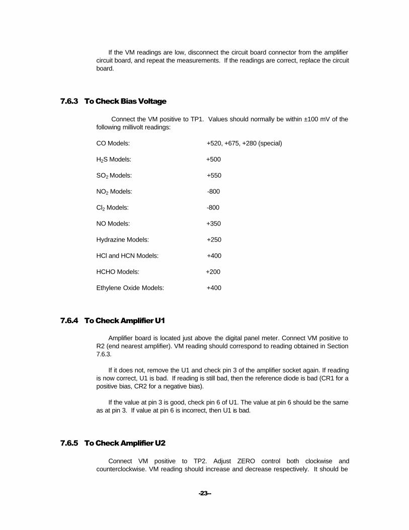
7.6.3 To Check Bias Voltage
Connect the VM positive to TP1. Values should normally be within ±100 mV of the following millivolt readings:
CO Models: +520, +675, +280 (special)
H2S Models: +500
SO2 Models: +550
NO2 Models: -800
Cl2 Models: -800
NO Models: +350
Hydrazine Models: +250
HCl and HCN Models: +400
HCHO Models: +200
Ethylene Oxide Models: +400
7.6.4 To Check Amplifier U1
Amplifier board is located just above the digital panel meter. Connect VM positive to R2 (end nearest amplifier). VM reading should correspond to reading obtained in Section 7.6.3.
If it does not, remove the U1 and check pin 3 of the amplifier socket again. If reading is now correct, U1 is bad. If reading is still bad, then the reference diode is bad (CR1 for a positive bias, CR2 for a negative bias).
If the value at pin 3 is good, check pin 6 of U1. The value at pin 6 should be the same as at pin 3. If value at pin 6 is incorrect, then U1 is bad.
7.6.5 To Check Amplifier U2
Connect VM positive to TP2. Adjust ZERO control both clockwise and counterclockwise. VM reading should increase and decrease respectively. It should be

-24--
possible to achieve both positive and negative voltages. If no voltage change occurs at TP2, U2 is defective.
7.6.6 To Check Amplifier U3 Adjust SPAN control totally clockwise (control is a 25-turn pot). Connect VM positive
to pin 9 of the amplifier board connector, and adjust ZERO control clockwise. VM reading should increase reaching 100 mV at full scale. U3 is defective if little or no voltage change is observed or if voltage is unusually high.
7.6.7 Conversion of TP2 Output to Micro amps
Sensor output is a current generated by the electrochemical reaction of the sample gas. This current passes through a feedback resistor (R5) and read out as a voltage at TP2. Feedback resistors vary as a function of specific sensor output and ppm ranges. In order to measure sensor characteristics, it is necessary to convert the TP2 reading in millivolts, to sensor output in micro amps according to:
= µA
Where F is the conversion factor, or feedback resistor in Kohms for a given range. For convenience, the value of F for resistor R5 is shown on a typed label on inside of panel meter.
7.6.8 Specific Output of Sensor
Pump off. Connect VM positive to TP2. Adjust ZERO control to a zero reading on VM. Attach sample bag containing calibration gas. Switch on pump and adjust flow to 0.5 lpm. Allow VM reading to stabilize.
e.g. 95 ppm CO gives VM reading of 1216 mV, if the conversion factor is 4, the total sensor current is 1216/4 or 304 µA. Specific output of the sensor is 304/95 or 3.2 µA/ppm.
7.6.9 Background Current of Sensor
Pump off. Remove banana plug from sensor. Connect VM positive to TP2. Adjust ZERO control to zero reading on VM. Reinsert banana plug. Allow time for the VM reading to stabilize.
e.g. VM reading is +225 mV, the conversion factor is 5, the background current is 225/5 or +45 µA. Background current may be positive or negative, so polarity should be noted. (The ZERO control compensates for this current)
TP2mv F

-25--
7.6.10 Span Gas Check
Knowing specific sensor output, an approximation can be made of true analysis of span gas. This is usually sufficient to determine whether calibration gas is faulty. A Factory record is maintained of specific output of each sensor.
e.g. A bottle of SO2 span gas gives VM reading of 980 mV in a sensor having a specific output of 28 µA/ppm. If the conversion factor is 5, the total current is 980/5 or 196 µA. At 28 µA/ppm the gas concentration is 196/28 or 7.0 ppm SO2.
7.7 Sensor Malfunction
7.7.1 Introduction
The sensor is a minor cause of instrument malfunction when properly maintained. Sensor life is determined by loss of water through evaporation into the sample stream. By periodically restoring the water and protecting the sensor with a sample intake filter, a long service life is assured. Rate of water loss is a function of temperature, humidity, and sample flow rate (0.5 liter/minute is recommended).
7.7.2 No Response to Gas
Total lack of instrument response to gas is NOT necessarily an indication of sensor failure. Check the sensor clamp and banana jack connections, and refer to Section 7.5.
7.8 Violent & Erratic Meter Kick. Sporadic False Alarms
The condition may result from exposure of the instrument to excessive vibration, or to frequent transport from one sampling area to another. Such erratic behavior will result in violent up and down fluctuation of the ppm readings causing sporadic and intermittent false alarms. This is due to erratic make-break contact of bias voltage on the sensor. Check the following:
Make sure the sensor banana plug is securely connected to the sensor jack.
Make sure the lug is securely attached to the sensor clamp, and clamp screw is tight.
Use 3/8" socket wrench to tighten the nuts securing circuit board to terminals of panel meter.
Make sure the connector is pushed down on circuit board.
Make sure the AC power cord is attached securely attached to the AC source.
-26--
7.9 Range Ratio Adjustment
Sensor readout is linear with concentration. If there is an apparent discrepancy in switching from one range to another, the range ratio setting may be off. Reset range ration as follows:
Zero unit in either range, then switch to the other range. If needle deflects, reset ZERO control and switch back to first range. Continue switching back and forth, resetting the ZERO control until no deflection of meter occurs. If this does not correspond to zero position on meter, adjust mechanical zero (screwdriver adjust) to zero reading scale.
7.10 Externally-Induced Malfunctions
7.10.1 Introduction
Since the function of the instrument is to analyze a sample stream introduced from the outside, external factors can influence instrument performance. Some of the more obvious ones are discussed below.
7.10.2 Defective Calibration Gas
Inasmuch as instrument accuracy depends on accuracy of the calibration gas, a defective calibration gas results in erroneous readings. Moreover, calibration gas concentrations much higher or much lower than the labeled values, generate apparent instrument malfunction during sample measurement, even though the analyzer is in proper working order.
7.10.2.1 Actual Concentration Lower Than Labeled Value
Causes high readings during sample measurements since the SPAN (instrument gain) is incorrectly adjusted higher to compensate for the lower concentration of the calibration gas. A pseudo-malfunction is an enhanced instrument instability and drift due to abnormally high gain setting. A second apparent malfunction may be the insufficient gain to reach calibration, giving the wrong conclusion that the sensor is defective.
7.10.2.2. Actual Concentration Higher Than Labeled Value
This results in erroneously low readings during sample measurements, since the SPAN is inadvertently set lower to compensate for the higher true concentration of the calibration gas.

-27--
A pseudo-malfunction is the inability to achieve calibration due to voltage clipping (amplifier overload) and/or current saturation. This condition is created when the actual concentration is sufficiently high to result in an output voltage or current in excess of amplifier capability. No damage results to the instrument or sensor. Sensor currents in excess of 20 mA will saturate the amplifier. This should rarely occur, as it would require the calibration gas to be off by 1 to 2 orders of magnitude. In some cases, voltage clipping may occur. The voltage at which this occurs, is determined by the feedback resistor (selected for sensor sensitivity and meter range). Voltage clipping occurs when the voltage measured at TP2 exceeds 12-13V.
7.10.3 Connections to Instrument Inlet
Special sampling or calibrating hook-ups to the inlet of the instrument may affect accuracy or response time of the analyzer. Dead space or voids cause an apparent slow response because the sensor sees a diluted sample, which increases in concentration as the void gas is replaced by the sample (this normally occurs in the first several minutes of calibration at the filter inlet). Other hook-ups may cause sensor pressurization or result in a vacuum being pulled on the sensor by the pump.
7.11 Negative Meter Deflection In Absence Of Gas
It may sometimes be observed (particularly for the 2 ppm full scale range) that the meter may go negative in the SAMPLE mode. If the presence of an interfering gas can be discounted, the likely cause is a change in the background current of the sensor. This results from a change in the effective interfacial reaction area at the sensing electrode, owing to a small pressure effect. The deflection magnitude, measurable by adjusting the ZERO control to 50% scale, is normally less than 0.2 ppm equivalent. If the magnitude is very much larger, this indicates that the instrument is excessively over-spanned, which is frequently the case with the chlorine monitor, owing to improper calibration procedure. (See Section 5 of the manual.) This deflection error can be compensated by zeroing the instrument with the pump on, using a zero gas or filter.
7.12 QUICK-CHECK Procedure
Introduction
This procedure will rapidly resolve most service problems. It requires no expertise, other than using a digital DC voltmeter. Because many users suffer from the "bad sensor" syndrome, these simple tests isolate the sensor from the circuit board and pinpoint the source of the trouble.
Before proceeding to the QUICK-CHECK procedure, read Section 7.6.1 for introductory information. The following steps must be done in the sequence indicated, and in a "Power-On" condition.

-28--
Disconnect sensor by pulling out banana plug.
Measure TP1 to Ground, and refer to Section 7.6.3.
DIAGNOSIS: If the TP1 reading differs greatly from the correct value, the AC power supply or U1 amplifier is defective. On correction of the problem, allow the sensor at least 24 hours to re-stabilize with power ON.
Connect DVM to TP2 and Ground
Adjust ZERO control knob completely clockwise, and record DVM reading. Note also if meter needle deflects up-scale with increasing ZERO adjustment. (If meter needle does not move, turn SPAN control several turns clockwise)
Adjust ZERO control totally counterclockwise and record DVM.
Refer to Section 7.6.7 to convert DVM readings to micro amp (µA) values.
DIAGNOSIS: Normal operation is indicated by the meter moving up-scale with adjustment of the ZERO control clockwise, and downscale into a negative deflection, with the ZERO being adjusted counterclockwise. TP2 should exceed +100 µA in the total clock- wise setting, and -100 µA in the total counterclockwise setting.
These results indicate the circuit board to be in working order. Failure of the panel meter needle to move (after SPAN adjusted upwards) indicates a faulty meter or U2 amplifier.
Re-zero the instrument and reinsert banana plug into sensor jack, meanwhile monitoring TP2.
DIAGNOSIS: An instantaneous large reading at TP2, followed by a decrease to a stable value, indicates sensor is functioning normally and is in working order.
If no TP2 response, check if sensor clamp is securely tightened around sensor.
Using a shorting lead, MOMENTARILY connect TP1 to Ground, while monitoring DVM at TP2.
For all models except the Chlorine and NO2 analyzers, TP2 will show a high positive value, which immediately becomes negative on removing the short, followed by a rapid decrease in negative value.
For the Chlorine and NO2 models, TP2 shows a high negative value, which becomes a high positive value on removing the short, rapidly decreasing with time.
DIAGNOSIS: The above response shows that the sensor is properly connected to the circuit board and should respond to gas. If it does not respond to calibration gas, check to see if pump is working, and all gas connections are secure. Check also for upstream flow restriction, by monitoring for restricted flow in the rotameter. Before doing this, however, check for secure connections to rotameter, by disconnecting sensor from the tubing leading to the rotameter, and finger-blocking the tubing end.
If pump and all fittings are okay, then either the calibration gas or the sensor is defective. Remove the sensor from the instrument and re-tighten the clamp around the sensor to

-29--
assure good electrical contact with sensor. Using a DVM in the DC Milliamps mode, MOMENTARILY connect the positive lead to the sensor clamp, and the negative lead to the banana jack. A DC current of a few milliamps to several tens of milliamps indicates the sensor is in good working order. A current of 1 or 2 mA or less is a sign of a defective sensor.
Is the sensor response to gas (rise and recovery time) sluggish? Is there an inability to achieve SPAN? Check sensor weight against labeled value.
DIAGNOSIS: A loss in weight of 100 grams or higher represents almost total loss of water. Add water to original total weight of sensor...no more than this. If water loss is not excessive (less than 50 grams), or if restoring water has no effect (allow 24 hours), sensor is either contaminated by foreign matter, or has been consumed (several thousand ppm-hours of usage). H2S sensors may suffer catalyst self-poisoning, in addition.

-30--
Warranty 8.1 INTERSCAN’s Warranty Policy
INTERSCAN CORPORATION warrants portable analyzers and continuous monitoring systems of its manufacture (sensors, batteries, fuses, lamps, tubing, fittings, filters, and scrubbers excepted) to be free from defects in material and workmanship for a period of one year from date of shipment. INTERSCAN CORPORATION warrants sensors of its manufacture to be free from defects in material and workmanship for a period of six months from date of shipment.
INTERSCAN CORPORATION's sole obligation under this warranty is limited to repairing or replacing, at its option, any item covered under this warranty, when such item is returned intact, prepaid to the factory (or designated service center).
This warranty does not apply to any of our products which have been repaired or altered by unauthorized persons, or which have been subject to misuse, negligence, or accident, incorrect wiring by others, installation or use not in accordance with instructions furnished by the manufacturer, or which have had the serial numbers altered, effaced or removed. The sensors are factory sealed and must not be opened or modified in the field for the warranty to remain in effect. This warranty is in lieu of all other warranties, whether expressed or implied.
Additionally, in a custom system, warranty on any component shall not exceed the manufacturer's warranty given to INTERSCAN CORPORATION.
Section
8

-31--
Parts List
Section
9

-32--
Schematics
Section
10

-33--
Return Authorization All returns for repairs require a "RETURN AUTHORIZATION NUMBER" issued by the INTERSCAN Service Department upon request.
This is done primarily to cause the user to contact the factory directly. The reason for this is that a high percentage of service problems are resolved over the telephone, avoiding the need for returning the instrument or part. In other cases, the Service Department may ask for the return of the circuit board only.
Should return of the instrument or part be advised by the Service Department, the "RETURN AUTHORIZATION NUMBER" will expedite prompt return of the repaired unit.
For service information, please contact:
INTERSCAN CORPORATION
Service Department
(800) 458-6153 ext. 121
(818) 882-2331 ext. 121
FAX (818) 341-0642
E-mail: [email protected]
Section
11

-34--
Index Subject Section
Alarm Set / Setting the Alarm 3.2.3
Amplifier 2.3.3
Buffer 2.3.4
Bypass 2.4.9
Calibration, Electronic 5.11
Calibration Gas Standards 5.2
Calibration Procedures 5.10
Calibration, Sample Bag 5.3
Calibrators 5.6
Chemical Scrubbers 6.3
Chemisorbable Gases 5.8
Diaphragm Pump 2.4.5
Electronics 2.3
Filter Clog / Vacuum Switch 2.4.7
Inlet Filter 2.4.2
Section
11
Section
12

-35--
Subject Section
Installation 3.1
INTERSCAN Sensor, The 2.2
Monitor Description 2.1
Monitor Mounting 3.1.2
Particulate Filter 6.2
Permeation Devices 5.4
Permeation Rate & PPM Calculation 5.7
Permeation Tube Manufacturers 5.9
Pneumatics 2.4
Power Off Alarm 3.1.7
Reference Supply 2.3.2
Rotameter 2.4.4
Rotating Beacon-Ray / Strobe Light 3.1.3
Sample Bag Calibration 5.3
Sample Tubing 2.4.3
Sampling 3.2.2
Sensor Maintenance 6.4
Sensor Principle of Operation 2.2.2
Tube Fittings 2.4.6
Vibratory Horn 3.1.4
Zeroing 3.2.1