Embed Size (px)
Citation preview
LDDM
Linear Direct Drive Motors
L2U Series

2
INA – Drives & Mechatronics GmbH & Co.
KG, a member of the Schaeffler Group,
is a specialist in linear and rotary direct
drives. To complement these products,
we also offer directly driven positioning
systems and all the necessary control-
lers and mechatronic assemblies.
In addition to standard products, IDAM
also develops and produces customised
drive solutions.
In modern machines and equipment,
direct drives are increasingly replacing
standard drive solutions because of
ever-stricter requirements for dynamics,
precision and cost-effectiveness.
Directly linking the motor and the mov-
ing mass increases the dynamic and
static rigidity, enabling high-perform-
ance positioning movements.
Direct drives are low wearing. This allows
maintenance and operating costs to be
reduced whilst also increasing availability.
For more than 20 years, teams at IDAM
have been developing and producing
direct drives and complex drive systems
for the following sectors: machine tools
and production machinery, automation,
productronics/semicon, measuring tech-
nology and medical engineering.
Models and simulations are integrated
into the development process for direct
drives and positioning systems, making
the process more efficient.
IDAM has a cutting-edge quality
management system. At IDAM, quality
management is a dynamic process
that is checked daily and continuously
improved. IDAM is certified to
DIN EN ISO 9001:2008.
The Perfect Drive for Every Application.
IDAM uses specially developed tools to develop and design the motors, including
tools for mechanical and thermal simulation. This produces results that our cus-
tomers can use to optimise their subsequent designs.
3
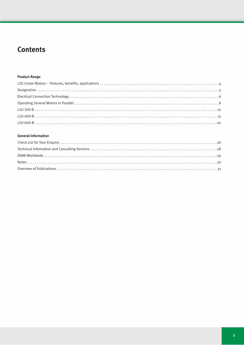
Contents
Product Range
L2U Linear Motors – Features, benefits, applications . . . . . . . . . . . . . . . . . . . . . . . . . . . . . . . . . . . . . . . . . . . . . . . . . . . . . . . . . . . . . . . . 4
Designation . . . . . . . . . . . . . . . . . . . . . . . . . . . . . . . . . . . . . . . . . . . . . . . . . . . . . . . . . . . . . . . . . . . . . . . . . . . . . . . . . . . . . . . . . . . . . . . . . . 5
Electrical Connection Technology. . . . . . . . . . . . . . . . . . . . . . . . . . . . . . . . . . . . . . . . . . . . . . . . . . . . . . . . . . . . . . . . . . . . . . . . . . . . . . . . . 6
Operating Several Motors in Parallel . . . . . . . . . . . . . . . . . . . . . . . . . . . . . . . . . . . . . . . . . . . . . . . . . . . . . . . . . . . . . . . . . . . . . . . . . . . . . . 8
L2U-200-B . . . . . . . . . . . . . . . . . . . . . . . . . . . . . . . . . . . . . . . . . . . . . . . . . . . . . . . . . . . . . . . . . . . . . . . . . . . . . . . . . . . . . . . . . . . . . . . . . . 10
L2U-400-B . . . . . . . . . . . . . . . . . . . . . . . . . . . . . . . . . . . . . . . . . . . . . . . . . . . . . . . . . . . . . . . . . . . . . . . . . . . . . . . . . . . . . . . . . . . . . . . . . . 15
L2U-600-B . . . . . . . . . . . . . . . . . . . . . . . . . . . . . . . . . . . . . . . . . . . . . . . . . . . . . . . . . . . . . . . . . . . . . . . . . . . . . . . . . . . . . . . . . . . . . . . . . .20
General Information
Check List for Your Enquiry . . . . . . . . . . . . . . . . . . . . . . . . . . . . . . . . . . . . . . . . . . . . . . . . . . . . . . . . . . . . . . . . . . . . . . . . . . . . . . . . . . . . .26
Technical Information and Consulting Services . . . . . . . . . . . . . . . . . . . . . . . . . . . . . . . . . . . . . . . . . . . . . . . . . . . . . . . . . . . . . . . . . . . .28
IDAM Worldwide . . . . . . . . . . . . . . . . . . . . . . . . . . . . . . . . . . . . . . . . . . . . . . . . . . . . . . . . . . . . . . . . . . . . . . . . . . . . . . . . . . . . . . . . . . . . .29
Notes . . . . . . . . . . . . . . . . . . . . . . . . . . . . . . . . . . . . . . . . . . . . . . . . . . . . . . . . . . . . . . . . . . . . . . . . . . . . . . . . . . . . . . . . . . . . . . . . . . . . . .30
Overview of Publications . . . . . . . . . . . . . . . . . . . . . . . . . . . . . . . . . . . . . . . . . . . . . . . . . . . . . . . . . . . . . . . . . . . . . . . . . . . . . . . . . . . . . . 31
44
L2U Linear MotorsFeatures, benefits, applications
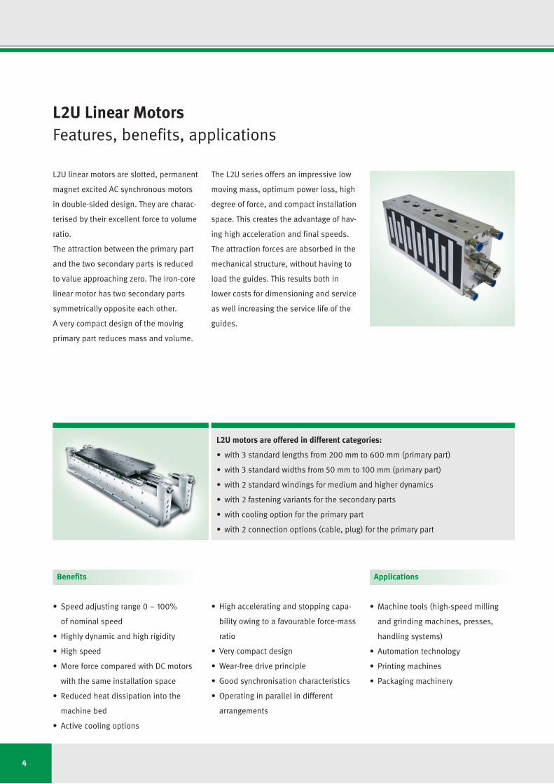
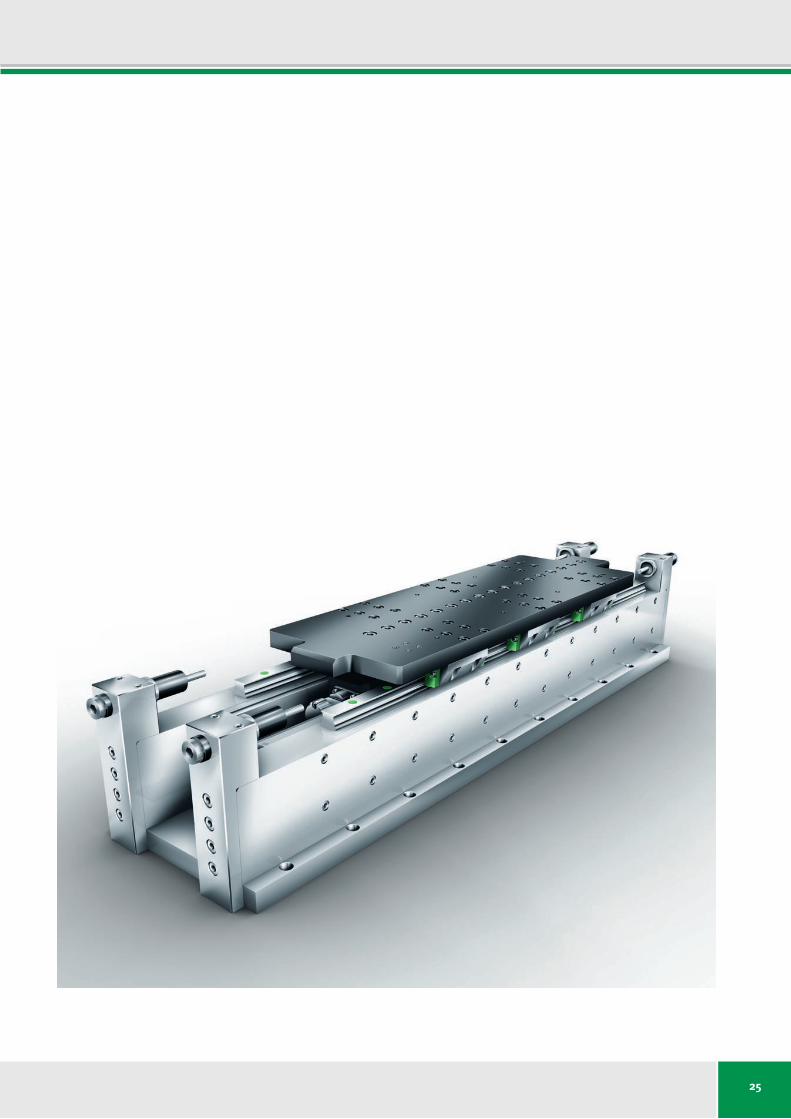
L2U linear motors are slotted, permanent
magnet excited AC synchronous motors
in double-sided design. They are charac-
terised by their excellent force to volume
ratio.
The attraction between the primary part
and the two secondary parts is reduced
to value approaching zero. The iron-core
linear motor has two secondary parts
symmetrically opposite each other.
A very compact design of the moving
primary part reduces mass and volume.
The L2U series offers an impressive low
moving mass, optimum power loss, high
degree of force, and compact installa tion
space. This creates the advantage of hav-
ing high acceleration and final speeds.
The attraction forces are absorbed in the
mechanical structure, without having to
load the guides. This results both in
lower costs for dimensioning and service
as well increasing the service life of the
guides.
L2U motors are offered in different categories:
• with3 standard lengths from 200 mm to 600 mm (primary part)
• with3 standard widths from 50 mm to 100 mm (primary part)
• with2 standard windings for medium and higher dynamics
• with2 fastening variants for the secondary parts
• withcoolingoptionfortheprimarypart
• with2 connection options (cable, plug) for the primary part
Benefits
• Speedadjustingrange0 – 100%
of nominal speed
• Highlydynamicandhighrigidity
• Highspeed
• MoreforcecomparedwithDCmotors
with the same installation space
• Reducedheatdissipationintothe
machine bed
• Activecoolingoptions
• Highacceleratingandstoppingcapa-
bility owing to a favourable force-mass
ratio
• Verycompactdesign
• Wear-freedriveprinciple
• Goodsynchronisationcharacteristics
• Operating in parallel in different
arrangements
Applications
• Machinetools(high-speedmilling
and grinding machines, presses,
handling systems)
• Automationtechnology
• Printingmachines
• Packagingmachinery
55
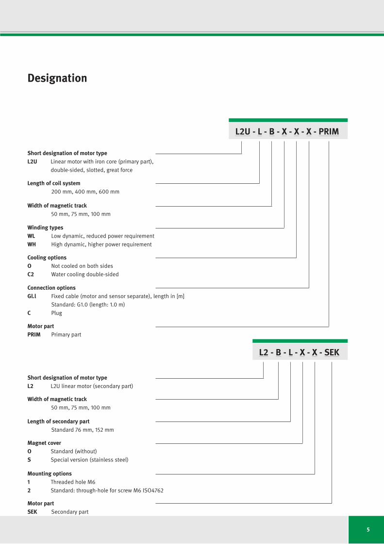
Designation
L2U - L - B - X - X - X - PRIM
Length of coil system 200 mm, 400 mm, 600 mm
Width of magnetic track 50 mm, 75 mm, 100 mm
Winding typesWL Low dynamic, reduced power requirement
WH High dynamic, higher power requirement
Connection optionsGl.l Fixed cable (motor and sensor separate), length in [m]
Standard: G1.0 (length: 1.0 m)
C Plug
Cooling optionsO Not cooled on both sides
C2 Water cooling double-sided
Motor partPRIM Primary part
L2 - B - L - X - X - SEK
Short designation of motor typeL2 L2U linear motor (secondary part)
Width of magnetic track 50 mm, 75 mm, 100 mm
Length of secondary part Standard 76 mm, 152 mm
Magnet coverO Standard (without)
S Special version (stainless steel)
Mounting options1 Threaded hole M62 Standard: through-hole for screw M6 ISO4762
Motor partSEK Secondary part
Short designation of motor typeL2U Linear motor with iron core (primary part),
double-sided, slotted, great force
6
Electrical Connection Technology
The standard connections of the IDAM
motors are routed through the face end.
The cable length from the motor outlet
is 1.0 m or according to the customer's
request. The cross-section of the power
connection cable depends on the nominal
motor current, dimensioning is carried
out to nominal current Icw at Plw (cooled).
The sensor cable allows you to monitor
the temperature using PTC and KTY.
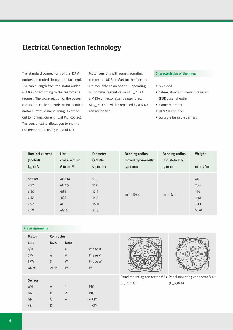
Motor versions with panel mounting
connectors M23 or M40 on the face end
are available as an option. Depending
on nominal current value at Icw <30 A
a M23-connector size is assembled.
At Icw >30 A it will be replaced by a M40
connector size.
Characteristics of the lines
• Shielded
• Oil-resistantandcoolant-resistant
(PURoutersheath)
• Flame-retardant
• UL/CSAcertified
• Suitableforcablecarriers
Nominal current Line Diameter Bending radius Bending radius Weight
(cooled) cross-section (± 10%) moved dynamically laid statically
Icw in A A in mm² dK in mm rd in mm rs in mm m in g/m
Sensor 4x0.14 5.1 40
M 22 4G2.5 11.0 230
M 30 4G4 12.5 310
M 37 4G6 14.5 440
M 52 4G10 18.0 700
M 70 4G16 21.5 1050
min. 10x d min. 5x d
Motor Connector
Core M23 M40
1/U 1 U Phase U
2/V 4 V PhaseV
3/W 3 W Phase W
GNYE 2/PE PE PE
Sensor
WH A 1 PTC
BN B 2 PTC
GN C + + KTY
YE D – – KTY
Pin assignments
Polbild M40
Polbild M23
Polbild M40
Polbild M23
Originalgrößein L2U-Broschüre
Polbild M40
Polbild M23
Polbild M40
Polbild M23
Originalgrößein L2U-Broschüre
Panel mounting connector M23
(Icw <30 A)
Panel mounting connector M40
(Icw >30 A)
7
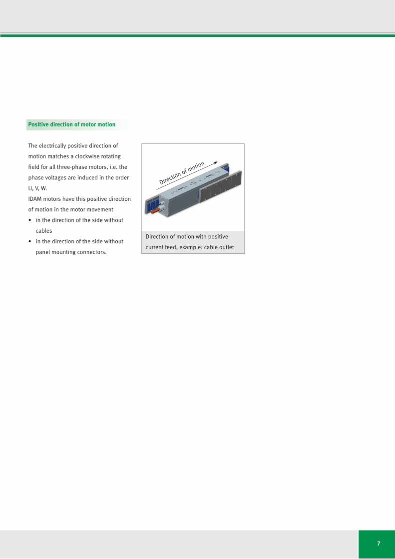
Positive direction of motor motion
The electrically positive direction of
motion matches a clockwise rotating
field for all three-phase motors, i.e. the
phase voltages are induced in the order
U,V,W.
IDAM motors have this positive direction
of motion in the motor movement
• inthedirectionofthesidewithout
cables
• inthedirectionofthesidewithout
panel mounting connectors.
Direction of motion with positive
current feed, example: cable outlet
Direction of motion
8
Janus arrangement
M M
UU
U1 U2 V2 W2V1 W1
VW
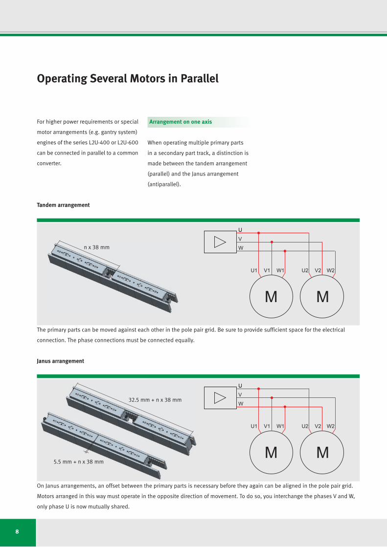
Operating Several Motors in Parallel
For higher power requirements or special
motor arrangements (e.g. gantry system)
engines of the series L2U-400 or L2U-600
can be connected in parallel to a common
converter.
Arrangement on one axis
When operating multiple primary parts
in a secondary part track, a distinction is
made between the tandem arrangement
(parallel) and the Janus arrangement
(antiparallel).
Tandem arrangement
M M
UU
U1 U2 V2 W2V1 W1
VW
The primary parts can be moved against each other in the pole pair grid. Be sure to provide sufficient space for the electrical
connection. The phase connections must be connected equally.
n x 38 mm
32.5 mm + n x 38 mm
5.5 mm + n x 38 mm
On Janus arrangements, an offset between the primary parts is necessary before they again can be aligned in the pole pair grid.
Motorsarrangedinthiswaymustoperateintheoppositedirectionofmovement.Todoso,youinterchangethephasesVandW,
only phase U is now mutually shared.
9
Setting for the phase coincidence
A check must always be made as to
whether the parallel motors are aligned
in phase to one another. If the phases
do not match up, the force constant and
efficiency are reduced depending on the
speed owing to induced short-circuit
currents.
Toadjustthephases,therespective
reverse voltage in the motors is measured
with a dual-channel oscilloscope during
simultaneous movement. The phase
displacement of the two curves should
not be greater than ±5°, so that good
static functioning of the interconnected
motors can be ensured.
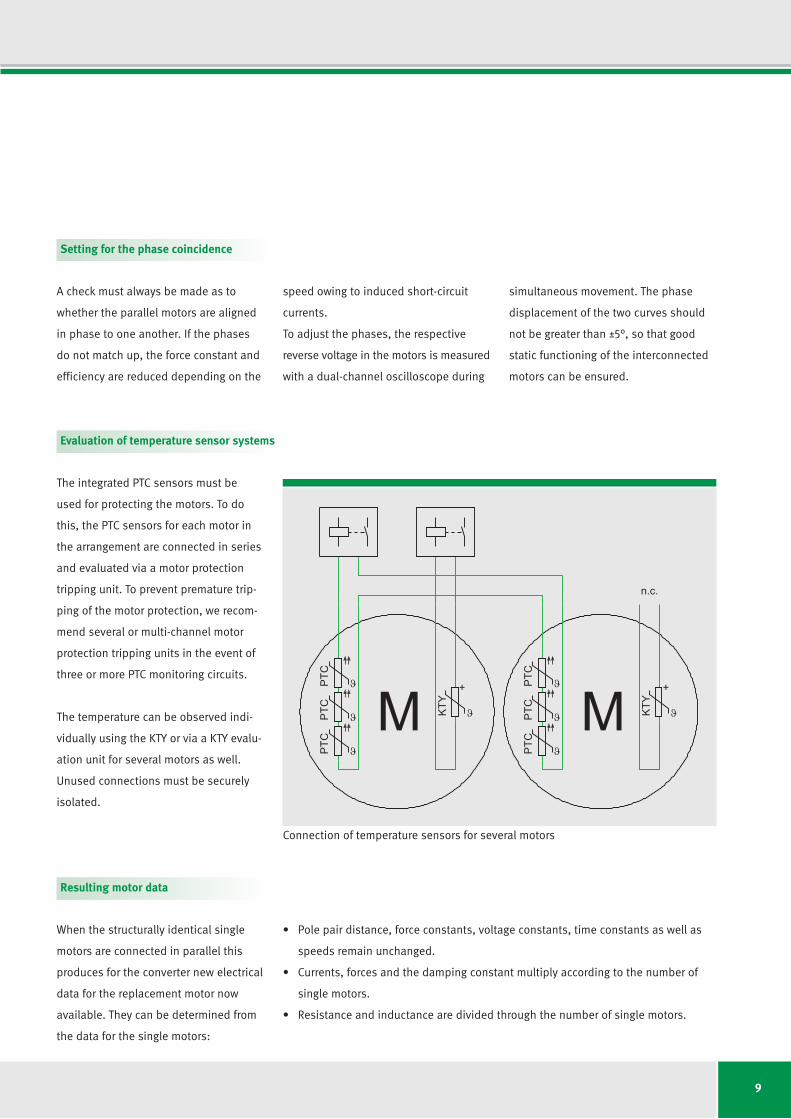
Evaluation of temperature sensor systems
The integrated PTC sensors must be
used for protecting the motors. To do
this, the PTC sensors for each motor in
the arrangement are connected in series
and evaluated via a motor protection
tripping unit. To prevent premature trip-
ping of the motor protection, we recom-
mend several or multi-channel motor
protection tripping units in the event of
three or more PTC monitoring circuits.
The temperature can be observed indi-
vid ually using the KTY or via a KTY evalu-
ation unit for several motors as well.
Unused connections must be securely
isolated.
M M
n.c.
PTC
PTC
PTC
PTC
PTC
PTC
KTY
+
KTY
+
Connection of temperature sensors for several motors
Resulting motor data
When the structurally identical single
motors are connected in parallel this
produces for the converter new electrical
data for the replacement motor now
available. They can be determined from
the data for the single motors:
• Polepairdistance,forceconstants,voltageconstants,timeconstantsaswellas
speeds remain unchanged.
• Currents,forcesandthedampingconstantmultiplyaccordingtothenumberof
single motors.
• Resistanceandinductancearedividedthroughthenumberofsinglemotors.

10
L2U-200-BDrawing: mounting option 1 (secondary part) – from below
n x1 0.1
38.7 (n -1) x 34.81
38 76
B 2a
B 2b
A - A
(n -1) x 762
==
32+0
.2 0
20P9
-0.02
-0.07
()
L1
L1c ± 0.1
L1a ± 0.1
L1b ± 0.0550
12
+0.20
50 +0.2016 P9 -0.02
-0.06( )
A
A
A
(grid 76)(Raster 76)L2
Gewindebohrung M6Threaded hole M6
A A
B 16
B 2B 2c
6
0.05
d12
d
7045
H 0.052 ±0.05
Side view: secondary part screw connection from below | plug connector and cooling (4 x cooling connection G 1/8, depth 14)
The illustrations show a L2U motor with plug and cooling.

11
L2U-200-BDrawing: mounting option 2 (secondary part) – from the top
(grid 76)(Raster 76)L2
38
B 2a
B 2b
A
(n -1) x 762
5.1
d K
L1
L1a ± 0.1
L1c ± 0.1L1b ± 0.05
38.7
==
(n -1) x 34.81
0.1
50+0.20
32+0
.2 0
50 +0.2016 P9 -0.02
-0.06( )
20P9
-0.02
-0.07
()
AA
A - A
Durchgangsbohrung für Schraube M6Through-hole for screw M6
12
n x1
76
A A
B 1B 2B 2c
0.05
d d
70H 0.052 ±
0.05
12
Side view: secondary part screw connection from the top | fixed cable, no cooling
The illustrations show a L2U motor with fixed cable and without cooling.
12
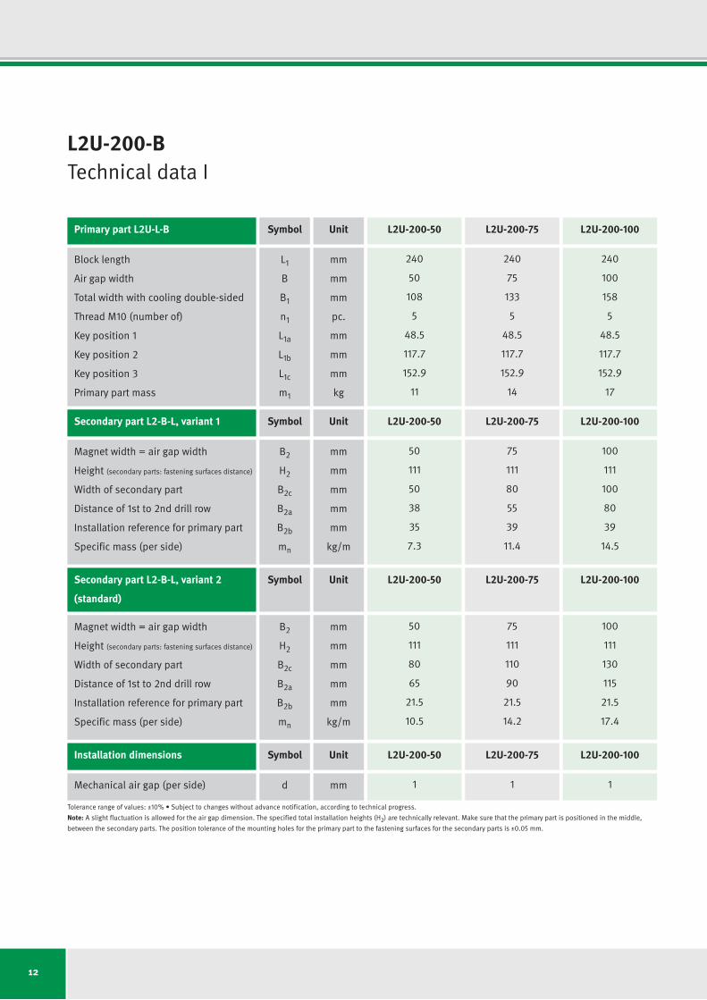
L2U-200-BTechnical data I
Primary part L2U-L-B Symbol Unit L2U-200-50 L2U-200-75 L2U-200-100
Secondary part L2-B-L, variant 1 Symbol Unit L2U-200-50 L2U-200-75 L2U-200-100
Installation dimensions Symbol Unit L2U-200-50 L2U-200-75 L2U-200-100
Secondary part L2-B-L, variant 2 Symbol Unit L2U-200-50 L2U-200-75 L2U-200-100
(standard)
Block length
Air gap width
Total width with cooling double-sided
Thread M10 (number of)
Key position 1
Key position 2
Key position 3
Primary part mass
Magnet width = air gap width
Height (secondary parts: fastening surfaces distance)
Width of secondary part
Distance of 1st to 2nd drill row
Installation reference for primary part
Specific mass (per side)
Mechanical air gap (per side)
Magnet width = air gap width
Height (secondary parts: fastening surfaces distance)
Width of secondary part
Distance of 1st to 2nd drill row
Installation reference for primary part
Specific mass (per side)
Tolerance range of values: ±10%•Subjecttochangeswithoutadvancenotification,accordingtotechnicalprogress.
Note: A slight fluctuation is allowed for the air gap dimension. The specified total installation heights (H2) are technically relevant. Make sure that the primary part is positioned in the middle,
between the secondary parts. The position tolerance of the mounting holes for the primary part to the fastening surfaces for the secondary parts is ±0.05 mm.
L1
B
B1
n1
L1a
L1b
L1c
m1
B2
H2
B2c
B2a
B2b
mn
d
B2
H2
B2c
B2a
B2b
mn
mm
mm
mm
pc.
mm
mm
mm
kg
mm
mm
mm
mm
mm
kg/m
mm
mm
mm
mm
mm
mm
kg/m
240
50
108
5
48.5
117.7
152.9
11
50
111
50
38
35
7.3
1
50
111
80
65
21.5
10.5
240
75
133
5
48.5
117.7
152.9
14
75
111
80
55
39
11.4
1
75
111
110
90
21.5
14.2
240
100
158
5
48.5
117.7
152.9
17
100
111
100
80
39
14.5
1
100
111
130
115
21.5
17.4
13
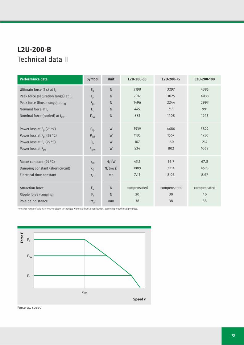
L2U-200-BTechnical data II
Force vs. speed
Forc
e F
Speed v
Fc
vlim
Fcw
Fp
Performance data Symbol Unit L2U-200-50 L2U-200-75 L2U-200-100
Ultimate force (1 s) at Iu
Peak force (saturation range) at Ip
Peak force (linear range) at Ipl
Nominal force at Ic
Nominal force (cooled) at Icw
Power loss at Fp (25 °C)
Power loss at Fpl (25 °C)
Power loss at Fc (25 °C)
Power loss at Fcw
Motor constant (25 °C)
Damping constant (short-circuit)
Electrical time constant
Attraction force
Rippleforce(cogging)
Pole pair distance
Fu
Fp
Fpl
Fc
Fcw
Plp
Plpl
Plc
Plcw
km
kd
tel
Fa
Fr
2tp
N
N
N
N
N
W
W
W
W
N/√W
N/(m/s)
ms
N
N
mm
2198
2017
1496
449
881
3539
1185
107
534
43.5
1889
7.13
compensated
20
38
3297
3025
2244
718
1408
4680
1567
160
802
56.7
3214
8.08
compensated
30
38
4395
4033
2993
991
1943
5822
1950
214
1069
67.8
4593
8.67
compensated
40
38
Tolerance range of values: ±10%•Subjecttochangeswithoutadvancenotification,accordingtotechnicalprogress.
14
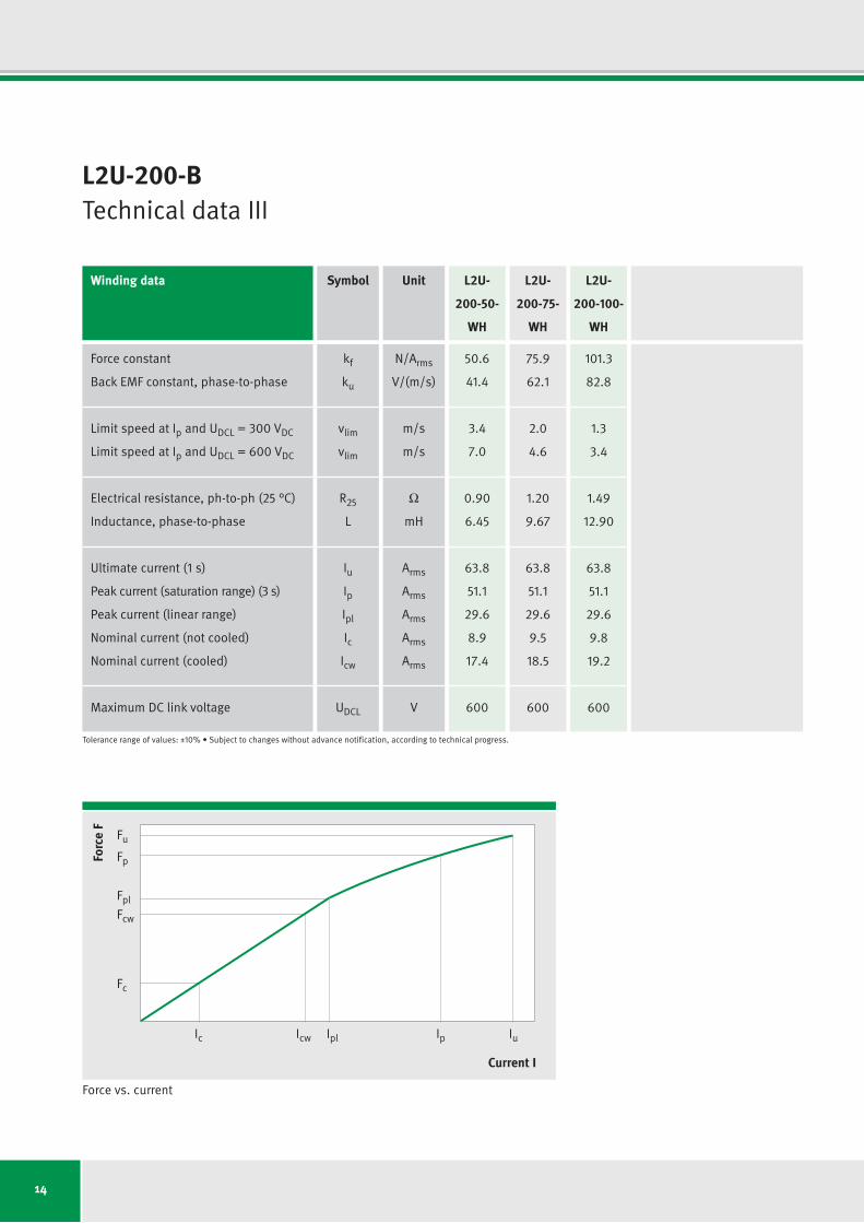
L2U-200-BTechnical data III
Force vs. current
Forc
e F
Current I
Fc
Icw IplIc Ip Iu
Fcw
Fpl
Fp
Fu
Winding data Symbol Unit L2U- L2U- L2U-
200-50- 200-75- 200-100-
WH WH WH
Force constant
Back EMF constant, phase-to-phase
Limit speed at Ip and UDCL = 300VDC
Limit speed at Ip and UDCL = 600VDC
Electrical resistance, ph-to-ph (25 °C)
Inductance, phase-to-phase
Ultimate current (1 s)
Peak current (saturation range) (3 s)
Peak current (linear range)
Nominal current (not cooled)
Nominal current (cooled)
Maximum DC link voltage
kf
ku
vlim
vlim
R25
L
Iu
Ip
Ipl
Ic
Icw
UDCL
N/Arms
V/(m/s)
m/s
m/s
Ω
mH
Arms
Arms
Arms
Arms
Arms
V
50.6
41.4
3.4
7.0
0.90
6.45
63.8
51.1
29.6
8.9
17.4
600
75.9
62.1
2.0
4.6
1.20
9.67
63.8
51.1
29.6
9.5
18.5
600
101.3
82.8
1.3
3.4
1.49
12.90
63.8
51.1
29.6
9.8
19.2
600
Tolerance range of values: ±10%•Subjecttochangeswithoutadvancenotification,accordingtotechnicalprogress.
15
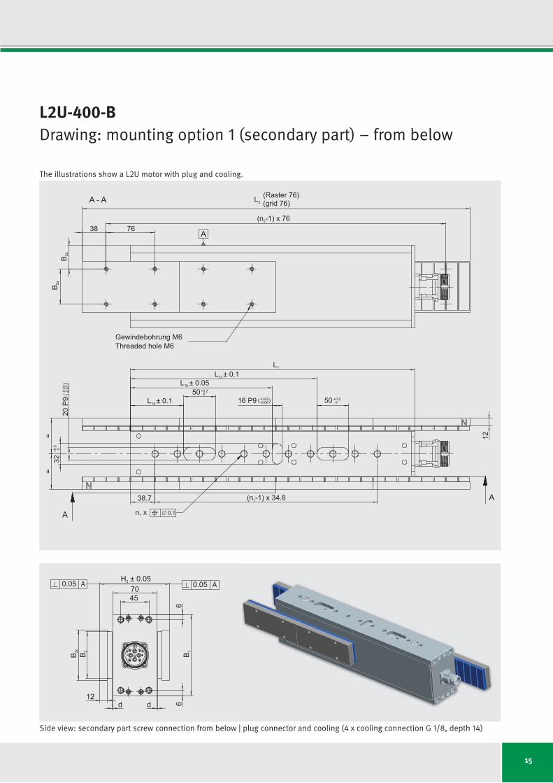
L2U-400-BDrawing: mounting option 1 (secondary part) – from below
n x1 0.1
38.7 (n -1) x 34.81
38 76
B 2a
B 2b
A - A
(n -1) x 762
==
32+0
.2 0
20P9
-0.02
-0.07
()
L1
L1c ± 0.1
L1a ± 0.1
L1b ± 0.0550
12
+0.20
50 +0.2016 P9 -0.02
-0.06( )
A
A
A
(grid 76)(Raster 76)L2
Gewindebohrung M6Threaded hole M6
A A
B 16
B 2B 2c
6
0.05
d12
d
7045
H 0.052 ±0.05
Side view: secondary part screw connection from below | plug connector and cooling (4 x cooling connection G 1/8, depth 14)
The illustrations show a L2U motor with plug and cooling.
16
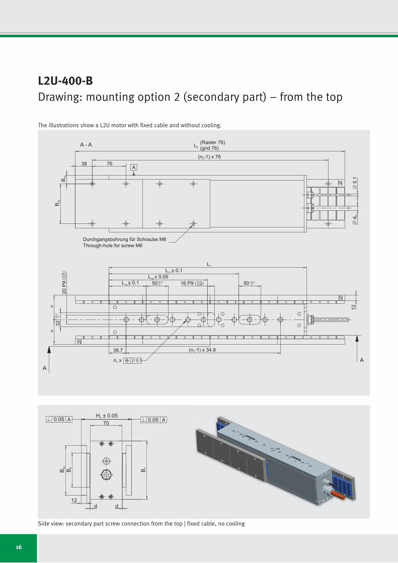
L2U-400-BDrawing: mounting option 2 (secondary part) – from the top
(grid 76)(Raster 76)L2
38
B 2a
B 2b
A
(n -1) x 762
5.1
d K
L1
L1a ± 0.1
L1c ± 0.1L1b ± 0.05
38.7
==
(n -1) x 34.81
0.1
50+0.20
32+0
.2 0
50 +0.2016 P9 -0.02
-0.06( )
20P9
-0.02
-0.07
()
AA
A - A
Durchgangsbohrung für Schraube M6Through-hole for screw M6
12n x1
76
A A
B 1B 2B 2c
0.05
d d
70H 0.052 ±
0.05
12
Side view: secondary part screw connection from the top | fixed cable, no cooling
The illustrations show a L2U motor with fixed cable and without cooling.
17
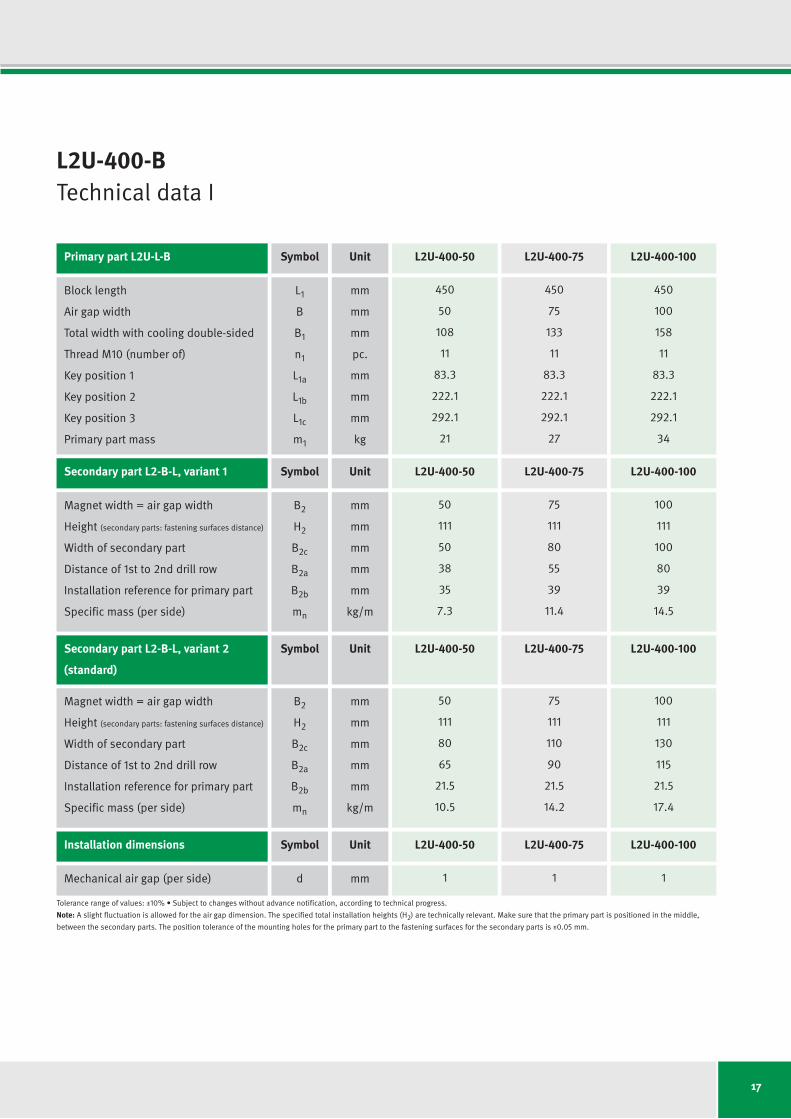
L2U-400-BTechnical data I
Primary part L2U-L-B Symbol Unit L2U-400-50 L2U-400-75 L2U-400-100
Secondary part L2-B-L, variant 1 Symbol Unit L2U-400-50 L2U-400-75 L2U-400-100
Installation dimensions Symbol Unit L2U-400-50 L2U-400-75 L2U-400-100
Secondary part L2-B-L, variant 2 Symbol Unit L2U-400-50 L2U-400-75 L2U-400-100
(standard)
Block length
Air gap width
Total width with cooling double-sided
Thread M10 (number of)
Key position 1
Key position 2
Key position 3
Primary part mass
Magnet width = air gap width
Height (secondary parts: fastening surfaces distance)
Width of secondary part
Distance of 1st to 2nd drill row
Installation reference for primary part
Specific mass (per side)
Mechanical air gap (per side)
Magnet width = air gap width
Height (secondary parts: fastening surfaces distance)
Width of secondary part
Distance of 1st to 2nd drill row
Installation reference for primary part
Specific mass (per side)
Tolerance range of values: ±10%•Subjecttochangeswithoutadvancenotification,accordingtotechnicalprogress.
Note: A slight fluctuation is allowed for the air gap dimension. The specified total installation heights (H2) are technically relevant. Make sure that the primary part is positioned in the middle,
between the secondary parts. The position tolerance of the mounting holes for the primary part to the fastening surfaces for the secondary parts is ±0.05 mm.
L1
B
B1
n1
L1a
L1b
L1c
m1
B2
H2
B2c
B2a
B2b
mn
d
B2
H2
B2c
B2a
B2b
mn
mm
mm
mm
pc.
mm
mm
mm
kg
mm
mm
mm
mm
mm
kg/m
mm
mm
mm
mm
mm
mm
kg/m
450
50
108
11
83.3
222.1
292.1
21
50
111
50
38
35
7.3
1
50
111
80
65
21.5
10.5
450
75
133
11
83.3
222.1
292.1
27
75
111
80
55
39
11.4
1
75
111
110
90
21.5
14.2
450
100
158
11
83.3
222.1
292.1
34
100
111
100
80
39
14.5
1
100
111
130
115
21.5
17.4
18
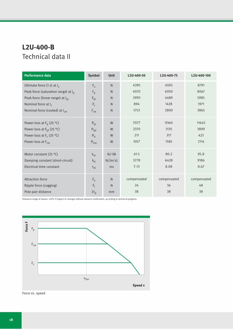
L2U-400-BTechnical data II
Performance data Symbol Unit L2U-400-50 L2U-400-75 L2U-400-100
Ultimate force (1 s) at Iu
Peak force (saturation range) at Ip
Peak force (linear range) at Ipl
Nominal force at Ic
Nominal force (cooled) at Icw
Power loss at Fp (25 °C)
Power loss at Fpl (25 °C)
Power loss at Fc (25 °C)
Power loss at Fcw
Motor constant (25 °C)
Damping constant (short-circuit)
Electrical time constant
Attraction force
Rippleforce(cogging)
Pole pair distance
Fu
Fp
Fpl
Fc
Fcw
Plp
Plpl
Plc
Plcw
km
kd
tel
Fa
Fr
2tp
N
N
N
N
N
W
W
W
W
N/√W
N/(m/s)
ms
N
N
mm
4395
4033
2993
894
1753
7077
2370
211
1057
61.5
3778
7.13
compensated
24
38
6593
6050
4489
1428
2800
9360
3135
317
1585
80.2
6428
8.08
compensated
36
38
8791
8067
5985
1971
3865
11643
3899
423
2114
95.8
9186
8.67
compensated
48
38
Tolerance range of values: ±10%•Subjecttochangeswithoutadvancenotification,accordingtotechnicalprogress.
Force vs. speed
Forc
e F
Speed v
Fc
vlim
Fcw
Fp
19
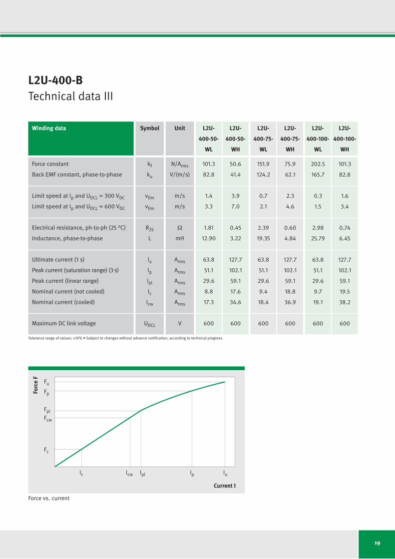
L2U-400-BTechnical data III
Winding data Symbol Unit L2U- L2U- L2U- L2U- L2U- L2U-
400-50- 400-50- 400-75- 400-75- 400-100- 400-100-
WL WH WL WH WL WH
Force constant
Back EMF constant, phase-to-phase
Limit speed at Ip and UDCL = 300VDC
Limit speed at Ip and UDCL = 600VDC
Electrical resistance, ph-to-ph (25 °C)
Inductance, phase-to-phase
Ultimate current (1 s)
Peak current (saturation range) (3 s)
Peak current (linear range)
Nominal current (not cooled)
Nominal current (cooled)
Maximum DC link voltage
kf
ku
vlim
vlim
R25
L
Iu
Ip
Ipl
Ic
Icw
UDCL
N/Arms
V/(m/s)
m/s
m/s
Ω
mH
Arms
Arms
Arms
Arms
Arms
V
101.3
82.8
1.4
3.3
1.81
12.90
63.8
51.1
29.6
8.8
17.3
600
50.6
41.4
3.9
7.0
0.45
3.22
127.7
102.1
59.1
17.6
34.6
600
151.9
124.2
0.7
2.1
2.39
19.35
63.8
51.1
29.6
9.4
18.4
600
75.9
62.1
2.3
4.6
0.60
4.84
127.7
102.1
59.1
18.8
36.9
600
202.5
165.7
0.3
1.5
2.98
25.79
63.8
51.1
29.6
9.7
19.1
600
101.3
82.8
1.6
3.4
0.74
6.45
127.7
102.1
59.1
19.5
38.2
600
Tolerance range of values: ±10%•Subjecttochangeswithoutadvancenotification,accordingtotechnicalprogress.
Force vs. current
Forc
e F
Current I
Fc
Icw IplIc Ip Iu
Fcw
Fpl
Fp
Fu
20
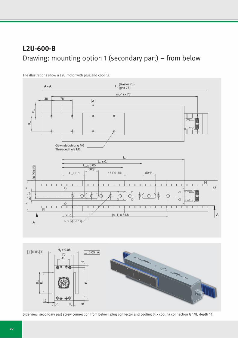
L2U-600-BDrawing: mounting option 1 (secondary part) – from below
n x1 0.1
38.7 (n -1) x 34.81
38 76
B 2a
B 2b
A - A
(n -1) x 762
==
32+0
.2 0
20P9
-0.02
-0.07
()
L1
L1c ± 0.1
L1a ± 0.1
L1b ± 0.0550
12
+0.20
50 +0.2016 P9 -0.02
-0.06( )
A
A
A
(grid 76)(Raster 76)L2
Gewindebohrung M6Threaded hole M6
A A
B 16
B 2B 2c
6
0.05
d12
d
7045
H 0.052 ±0.05
Side view: secondary part screw connection from below | plug connector and cooling (4 x cooling connection G 1/8, depth 14)
The illustrations show a L2U motor with plug and cooling.
21
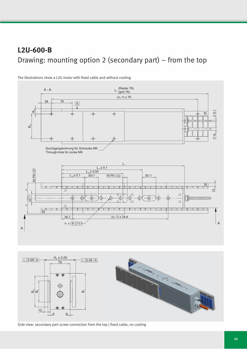
L2U-600-BDrawing: mounting option 2 (secondary part) – from the top
(grid 76)(Raster 76)L2
38
B 2a
B 2b
A
(n -1) x 762
5.1
d K
L1
L1a ± 0.1
L1c ± 0.1L1b ± 0.05
38.7
==
(n -1) x 34.81
0.1
50+0.20
32+0
.2 0
50 +0.2016 P9 -0.02
-0.06( )
20P9
-0.02
-0.07
()
AA
A - A
Durchgangsbohrung für Schraube M6Through-hole for screw M6
12
n x1
76
A A
B 1B 2B 2c
0.05
d d
70H 0.052 ±
0.05
12
Side view: secondary part screw connection from the top | fixed cable, no cooling
The illustrations show a L2U motor with fixed cable and without cooling.
22
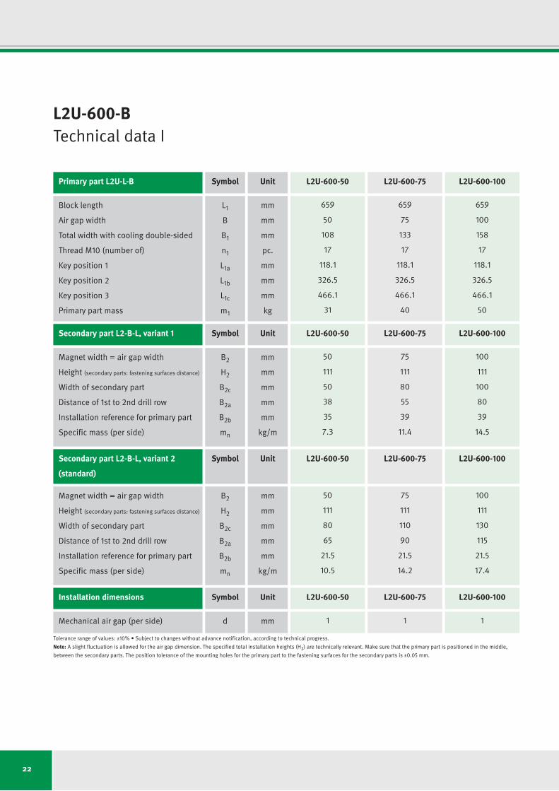
L2U-600-BTechnical data I
Primary part L2U-L-B Symbol Unit L2U-600-50 L2U-600-75 L2U-600-100
Secondary part L2-B-L, variant 1 Symbol Unit L2U-600-50 L2U-600-75 L2U-600-100
Installation dimensions Symbol Unit L2U-600-50 L2U-600-75 L2U-600-100
Secondary part L2-B-L, variant 2 Symbol Unit L2U-600-50 L2U-600-75 L2U-600-100
(standard)
Block length
Air gap width
Total width with cooling double-sided
Thread M10 (number of)
Key position 1
Key position 2
Key position 3
Primary part mass
Magnet width = air gap width
Height (secondary parts: fastening surfaces distance)
Width of secondary part
Distance of 1st to 2nd drill row
Installation reference for primary part
Specific mass (per side)
Mechanical air gap (per side)
Magnet width = air gap width
Height (secondary parts: fastening surfaces distance)
Width of secondary part
Distance of 1st to 2nd drill row
Installation reference for primary part
Specific mass (per side)
Tolerance range of values: ±10%•Subjecttochangeswithoutadvancenotification,accordingtotechnicalprogress.
Note: A slight fluctuation is allowed for the air gap dimension. The specified total installation heights (H2) are technically relevant. Make sure that the primary part is positioned in the middle,
between the secondary parts. The position tolerance of the mounting holes for the primary part to the fastening surfaces for the secondary parts is ±0.05 mm.
L1
B
B1
n1
L1a
L1b
L1c
m1
B2
H2
B2c
B2a
B2b
mn
d
B2
H2
B2c
B2a
B2b
mn
mm
mm
mm
pc.
mm
mm
mm
kg
mm
mm
mm
mm
mm
kg/m
mm
mm
mm
mm
mm
mm
kg/m
659
50
108
17
118.1
326.5
466.1
31
50
111
50
38
35
7.3
1
50
111
80
65
21.5
10.5
659
75
133
17
118.1
326.5
466.1
40
75
111
80
55
39
11.4
1
75
111
110
90
21.5
14.2
659
100
158
17
118.1
326.5
466.1
50
100
111
100
80
39
14.5
1
100
111
130
115
21.5
17.4

23
L2U-600-BTechnical data II
Performance data Symbol Unit L2U-600-50 L2U-600-75 L2U-600-100
Ultimate force (1 s) at Iu
Peak force (saturation range) at Ip
Peak force (linear range) at Ipl
Nominal force at Ic
Nominal force (cooled) at Icw
Power loss at Fp (25 °C)
Power loss at Fpl (25 °C)
Power loss at Fc (25 °C)
Power loss at Fcw
Motor constant (25 °C)
Damping constant (short-circuit)
Electrical time constant
Attraction force
Rippleforce(cogging)
Pole pair distance
Fu
Fp
Fpl
Fc
Fcw
Plp
Plpl
Plc
Plcw
km
kd
tel
Fa
Fr
2tp
N
N
N
N
N
W
W
W
W
N/√W
N/(m/s)
ms
N
N
mm
6593
6050
4489
1338
2624
10616
3555
316
1579
75.3
5667
7.13
compensated
30
38
9890
9075
6733
2137
4192
14040
4702
474
2369
98.2
9642
8.08
compensated
45
38
13186
12100
8978
2950
5786
17465
5849
632
3159
117.4
13780
8.67
compensated
61
38
Tolerance range of values: ±10%•Subjecttochangeswithoutadvancenotification,accordingtotechnicalprogress.
Force vs. speed
Forc
e F
Speed v
Fc
vlim
Fcw
Fp
24
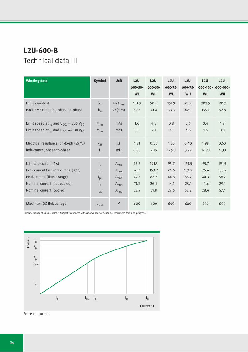
L2U-600-BTechnical data III
Winding data Symbol Unit L2U- L2U- L2U- L2U- L2U- L2U-
600-50- 600-50- 600-75- 600-75- 600-100- 600-100-
WL WH WL WH WL WH
Force constant
Back EMF constant, phase-to-phase
Limit speed at Ip and UDCL = 300VDC
Limit speed at Ip and UDCL = 600VDC
Electrical resistance, ph-to-ph (25 °C)
Inductance, phase-to-phase
Ultimate current (1 s)
Peak current (saturation range) (3 s)
Peak current (linear range)
Nominal current (not cooled)
Nominal current (cooled)
Maximum DC link voltage
kf
ku
vlim
vlim
R25
L
Iu
Ip
Ipl
Ic
Icw
UDCL
N/Arms
V/(m/s)
m/s
m/s
Ω
mH
Arms
Arms
Arms
Arms
Arms
V
101.3
82.8
1.6
3.3
1.21
8.60
95.7
76.6
44.3
13.2
25.9
600
50.6
41.4
4.2
7.1
0.30
2.15
191.5
153.2
88.7
26.4
51.8
600
151.9
124.2
0.8
2.1
1.60
12.90
95.7
76.6
44.3
14.1
27.6
600
75.9
62.1
2.6
4.6
0.40
3.22
191.5
153.2
88.7
28.1
55.2
600
202.5
165.7
0.4
1.5
1.98
17.20
95.7
76.6
44.3
14.6
28.6
600
101.3
82.8
1.8
3.3
0.50
4.30
191.5
153.2
88.7
29.1
57.1
600
Tolerance range of values: ±10%•Subjecttochangeswithoutadvancenotification,accordingtotechnicalprogress.
Force vs. current
Forc
e F
Current I
Fc
Icw IplIc Ip Iu
Fcw
Fpl
Fp
Fu
25
26
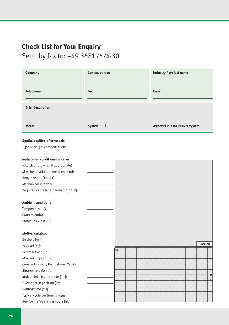
Check List for Your EnquirySend by fax to: +49 3681 7574-30
Company Contact person Industry / project name
Telephone Fax E-mail
Brief description
Motor System Axis within a multi-axis system
Spatial position of drive axis
Type of weight compensation:
Installation conditions for drive
(sketch or drawing, if appropriate)
Max. installation dimensions [mm]:
(length/width/height)
Mechanical interface:
Requiredcablelengthfrommotor[m]:
Ambient conditions
Temperature [K]:
Contamination:
Protection class (IP):
Motion variables
Stroke s [mm]:
Payload [kg]:
External forces [N]:
Maximum speed [m/s]:
Constant velocity fluctuations [%] at:
Shortest acceleration
and/or deceleration time [ms]:
Overshoot in position [µm]:
Settling time [ms]:
Typical cycle per time (diagram):
Service life/operating hours [h]:
t
s
sketch
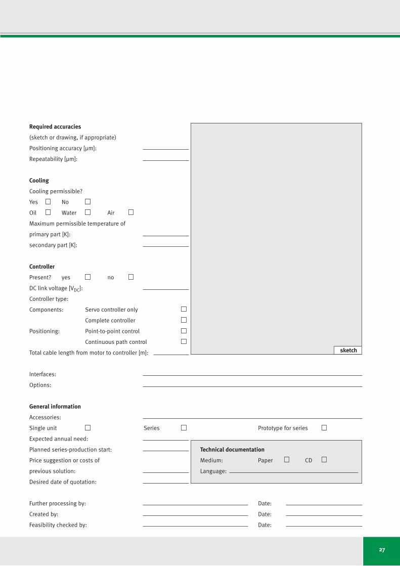
27
Required accuracies
(sketch or drawing, if appropriate)
Positioning accuracy [µm]:
Repeatability[µm]:
Cooling
Cooling permissible?
Yes No
Oil Water Air
Maximum permissible temperature of
primary part [K]:
secondary part [K]:
Controller
Present? yes no
DClinkvoltage[VDC]:
Controller type:
Components: Servo controller only
Complete controller
Positioning: Point-to-point control
Continuous path control
Total cable length from motor to controller [m]:
Interfaces:
Options:
General information
Accessories:
Single unit Series Prototype for series
Expected annual need:
Planned series-production start:
Price suggestion or costs of
previous solution:
Desired date of quotation:
Further processing by: Date:
Created by: Date:
Feasibility checked by: Date:
sketch
Technical documentation
Medium: Paper CD
Language:
28
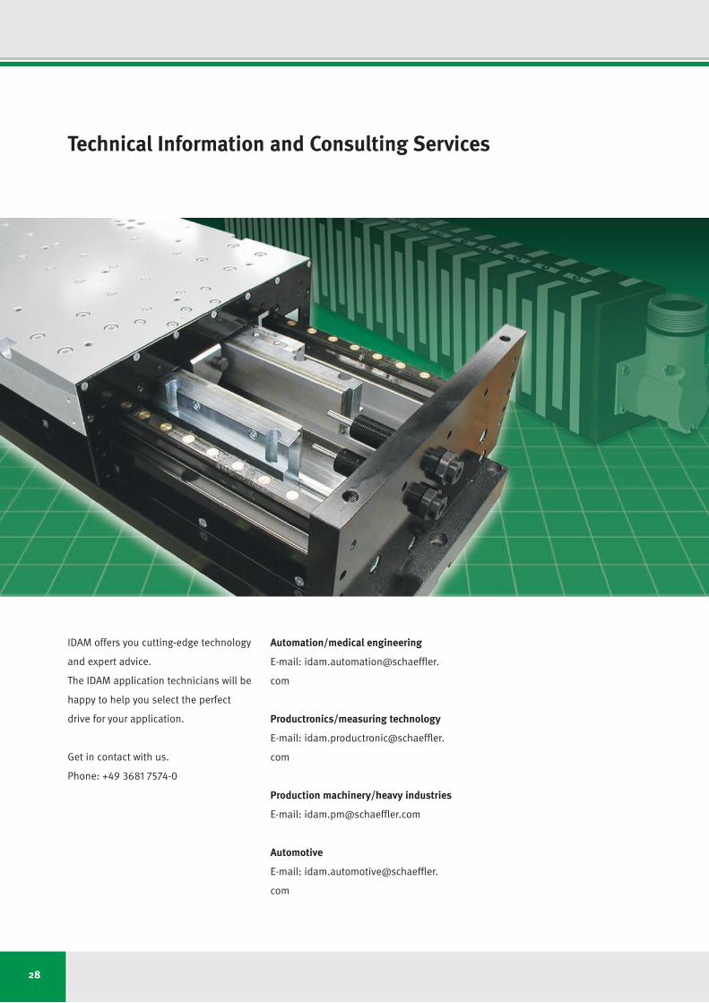
Technical Information and Consulting Services
IDAM offers you cutting-edge technology
and expert advice.
The IDAM application technicians will be
happy to help you select the perfect
drive for your application.
Get in contact with us.
Phone: +49 3681 7574-0
Automation/medical engineering
E-mail: idam.automation@schaeffler.
com
Productronics/measuring technology
E-mail: idam.productronic@schaeffler.
com
Production machinery/heavy industries
E-mail: [email protected]
Automotive
E-mail: idam.automotive@schaeffler.
com

29
IDAM Worldwide
AustriaPhone: +43 2672 2023332E-mail: [email protected]
CanadaPhone: +780 980 3016E-mail: [email protected]
ChinaPhone: +86 21 39576465E-mail: [email protected]
FinlandPhone: +358 207 366238E-mail: [email protected]
IsraelE-mail: [email protected]
ItalyPhone: +39 0321 929267 E-mail: [email protected]
JapanPhone: +81 45 274 8302E-mail: [email protected]
KoreaPhone: +82 2 311 3096 E-mail: [email protected]
NetherlandsPhone: +31 342 403208 E-mail: [email protected]
RussiaPhone: +7 495 7377660E-mail: [email protected]
Singapore/MalaysiaPhone: +65 6540 8683E-mail: [email protected]
Spain/PortugalPhone: +34 93 4803679E-mail: [email protected]
SwitzerlandPhone: +41 71 4666312E-mail: [email protected]
TaiwanE-mail: [email protected]
United KingdomE-mail: [email protected]
USAPhone: +1 704 5167517E-mail: [email protected]
Other countriesE-mail: [email protected]

30
Notes

31
Overview of Publications
Are you interested in detailed technical information?
We would be happy to send you our product brochures. Contact us: [email protected]
We would be happy to provide you with
product brochures for our electronic
assemblies and system solutions.
All information about our motors and
systems can also be found on our
website at www.idam.de.
LDDM
Linear Direct Drive Motors
L1 Series
1
RDDM
Rotary Direct Drive Motors
LDDM
Linear Direct Drive Motors
L2U Series
1
RDDM
Rotary Direct Drive Motors
RKI Series
1
RDDS
Rotary Direct Drive Systems
RDDS1 Matrix
RDDS2 Matrix
1
X/Y Positioning Systems
based on
Planar Motor Technology
1
IDAM Direct Drives
The perfect solution for every application
anywhere in the world.
Togetherwe move
theworld.
LDDM – Linear Direct
Drive Motors: L1 Series
RDDM–RotaryDirect
Drive Motors
LDDM – Linear Direct
Drive Motors: L2U Series
RDDM–RotaryDirect
DriveMotors:RKISeries
LDDM – Linear Direct
Drive Motors: UPL Series
RDDS–RotaryDirect
Drive Systems: RDDS1,
RDDS2 Matrix
X/Y Positioning Systems
based on Planar Motor
Technology
Product Overview:
IDAM Direct Drives
1
LDDM
Linear Direct Drive Motors
UPL Series
Issue: May 2014ISubjecttochangeswithoutadvancenotification,accordingtotechnicalprogress.IPhotos:IDAMGmbH&Co.KG
INA – Drives & Mechatronics GmbH & Co. KG
Mittelbergstrasse 2
98527 Suhl, Germany
Phone +49 3681 I 7574-0
Fax +49 3681 I 7574-30
E-mail [email protected]
Web www.idam.de