Embed Size (px)
Citation preview

U.S. Department of EnergyAnnual Merit Review
Presenter: Larry ChaneyNational Renewable Energy Laboratory
P.I. : John Rugh
Wednesday May 11, 2011
Project ID: VSS045
National Renewable Energy Laboratory Innovation for Our Energy Future
LDV HVAC Model Development and Validation
This presentation does not contain any proprietary, confidential, or otherwise restricted information
HIGH SPEED RAM AIR FLOWIDLE PULL OR PUSH AIR FLOW
CONDENSER
HIGH SIDECHARGE PORT
DISCHARGEMUFFLER
HIGH PRESSUREDISCHARGE LINE
LOW SIDECHARGE PORT
LOW PRESSURESUCTION LINE
BLOCKTXV
RADIATOR
HIGH PRESSURETRANSDUCER/SWITCH
COLD DISCHARGE AIRINTO VEHICLE INTERIOR
EVAPORATOR
CRANKSHAFTPULLEY
HIGH PRESSURELIQUID LINE
HIGH PRESSURE HIGH TEMPERATURE GAS
HIGH PRESSURE HIGH TEMPERATURE LIQUIDLOW PRESSURE LOW TEMPERATURE LIQUID/GASLOW PRESSURE LOW TEMPERATURE GAS
CLUTCH CYCLINGTHERMISTER
COMPRESSOR& CLUTCH
COMPRESSORPULLEY
HIGH PRESSURERELIEF VALVE
RECEIVER/DRIER
HIGH PRESSURE HIGH TEMPERATURE GAS/LIQUID
Diagram courtesy of Visteon Corp.

Overview
National Renewable Energy Laboratory Innovation for Our Energy Future
• Project start date: FY11(leverage FY10 CoolCalc work)
• Project end date: FY12• Percent complete: 25%
• Cost• Computational models, design
and simulation methodologies • Constant advances in
technology (require modeling and simulation tools to be updated)
• Total project funding– DOE share: $300k– Contractor share: $0.00
• FY10 Funding: $0k• FY11 Funding: $300k
Timeline
Budget
Barriers
• Collaboration– Argonne National Laboratory– Visteon
• Project lead: NREL
Partners
2

THE CHALLENGE
Project Description - Relevance
National Renewable Energy Laboratory Innovation for Our Energy Future3
THE OPPORTUNITY
• Reducing A/C load will lead to increased acceptance of electric vehicles.
• Tool needed to assess impact on advanced vehicles.
• Will help to achieve the president’s goal of 1 million EV by 2015.
• A/C load is the largest auxiliary load.
• A/C loads account for more than 5% of the fuel used annually for light duty vehicles in the US*
• A/C load can have a significant effect on EV, PHEV, HEV performance.
– Mitsubishi reports that the range of the i-MiEV can be reduced by as much as 50% on the Japan 10-15 mode when the AC is operating**
– Hybrid vehicles have 22% lower fuel economy with AC on***
• Increased cooling demands by EV may impact AC system
* Rugh et al, 2004 Earth Technologies Forum/Mobile Air Conditioning Summit.** Umezu et. al, 2010 SAE Automotive Refrigerant & System Efficiency Symposium*** INEL – in Vehicle Technologies Program 2007 annual report, p145.

National Renewable Energy Laboratory Innovation for Our Energy Future
Objectives - Relevance
4
• Overall Objectives– The objective of this project is to develop analysis tools to assess the
impact of technologies that reduce the thermal load, improve the climate control efficiency, and reduce vehicle fuel consumption
– To assist light-duty vehicle modeling, the A/C model framework developed in FY10 for heavy-duty vehicles will be modified to support light-duty vehicle simulations.
– This light-duty A/C model will provide the basis for future development of a detailed, validated, heavy-duty vehicle A/C model.
• FY11 Objectives– Develop a light-duty vehicle (LDV) A/C model that simulates
A/C performance and generates electrical and mechanical loads.
– LDV A/C components will be developed and implemented in the model framework.
– LDV A/C system simulations and the interface with Autonomie will be demonstrated.

Milestones - Relevance
National Renewable Energy Laboratory Innovation for Our Energy Future
Dates Month Key Milestone
2010 Apr • CoolCalc AC model framework demonstrated
2010 Sept • AC model framework integrated into CoolCalc
2011 August• DOE Milestone summary report• Demonstrate LDV system simulation• Demonstrate integration with Autonomie
5
COLD DISCHARGE AIRINTO VEHICLE INTERIOR
EVAPORATOR
Diagram courtesy of Visteon Corp.

Approach- Matlab/Simulink based simulation tool
National Renewable Energy Laboratory Innovation for Our Energy Future6
• Easily interfaced to Autonomie vehicle simulation tool.• Flexible software platform, capable of modeling vapor
compression refrigeration cycle.• Model refrigerant lines and the heat exchangers as 1D finite
volumes, accounting for the length-wise distribution of refrigerant and flow properties.
• Include all major components, such as the compressor, the condenser the expansion device, the evaporator, and the accumulator/dryer (receiver/dryer) in the refrigeration system.
• Is the basis for future development of a detailed, validated, heavy-duty vehicle A/C model.

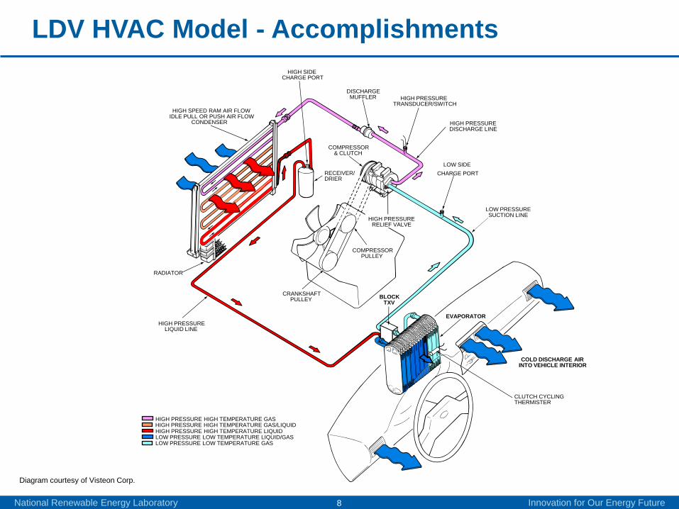
LDV HVAC Model - Accomplishments
National Renewable Energy Laboratory Innovation for Our Energy Future7
AC system model development• 1-D Finite element formulation• Fully transient model• Model built up from line components• Compression with adiabatic or volumetric efficiency as input
Detailed models built up from basic line building block.
7
Evaporator
Compressor
Condenser
Expansion Valve
Liquid
Vapor
Liquid + Vapor
Vapor
WarmAir
ColdAir
Fan
Receiver/Dryer
Liquid water
CoolingAir
LDV HVAC Model - Accomplishments
National Renewable Energy Laboratory Innovation for Our Energy Future8
Diagram courtesy of Visteon Corp.
HIGH SPEED RAM AIR FLOWIDLE PULL OR PUSH AIR FLOW
CONDENSER
HIGH SIDECHARGE PORT
DISCHARGEMUFFLER
HIGH PRESSUREDISCHARGE LINE
LOW SIDECHARGE PORT
LOW PRESSURESUCTION LINE
BLOCKTXV
RADIATOR
HIGH PRESSURETRANSDUCER/SWITCH
COLD DISCHARGE AIRINTO VEHICLE INTERIOR
EVAPORATOR
CRANKSHAFTPULLEY
HIGH PRESSURELIQUID LINE
HIGH PRESSURE HIGH TEMPERATURE GAS
HIGH PRESSURE HIGH TEMPERATURE LIQUIDLOW PRESSURE LOW TEMPERATURE LIQUID/GASLOW PRESSURE LOW TEMPERATURE GAS
CLUTCH CYCLINGTHERMISTER
COMPRESSOR& CLUTCH
COMPRESSORPULLEY
HIGH PRESSURERELIEF VALVE
RECEIVER/DRIER
HIGH PRESSURE HIGH TEMPERATURE GAS/LIQUID

LDV HVAC Model - Accomplishments
National Renewable Energy Laboratory Innovation for Our Energy Future9

LDV HVAC Model - Accomplishments
National Renewable Energy Laboratory Innovation for Our Energy Future10
Hot Vapor in
Sub-cooled liquid out
De-superheating RegionBegin Condensing
First Pass
Second Pass
Third Pass
Last Pass
Sub-cooled liquid Region
Diagram courtesy of Visteon Corp.
Development of Component ModelsExample: Condenser ModelComplex heat exchanger
•Multiple passes•Multi-channel tubes•Micro channels•Multiple refrigerant phases

LDV HVAC Model - Accomplishments
National Renewable Energy Laboratory Innovation for Our Energy Future11

LDV HVAC Model - Accomplishments
National Renewable Energy Laboratory Innovation for Our Energy Future12

LDV HVAC Model - Accomplishments
National Renewable Energy Laboratory Innovation for Our Energy Future13
0 100 200 300 400 500 600 700-4000
-2000
0
2000
4000
6000
8000
10000
Time [sec]
Hea
t tra
nsfe
r rat
e, P
ower
[W]
condenserevaporatorcompressorbalance
System Model Transient Example

LDV HVAC Model - Accomplishments
National Renewable Energy Laboratory Innovation for Our Energy Future14
System Model Transient Example
100 150 200 250 300 350 400 450 50010
1
102
103
104
Pre
ssur
e [k
Pa]
Specific Enthalpy [kJ/kg]
Thermodynamic Cycle on the P-h Diagram
mix boundarycompressorcond1cond2orifice tubeevap1evap2aevap2bevap3evap4

LDV HVAC Model - Accomplishments
National Renewable Energy Laboratory Innovation for Our Energy Future15
System IntegrationA/C system inputs/outputs
into/out of Automomie data bus
A/C System
Engine RPMVehicle Speed
Cabin Air Temperature
Cabin Blower SettingCondenser Fan
Cabin Air Humidity
Compressor Power (mech or elec)
Blower Power (elec)
A/C Vent Temperature
Condenser fan power
Ambient Temperature

Collaboration
• Argonne National Lab
• Visteon Corp.
National Renewable Energy Laboratory Innovation for Our Energy Future16

Future Work
• FY11– Complete component development.– Continue system development.– Develop simplified cabin thermal model.– Demonstrate integration with Autonomie.– Demonstrate LDV AC system simulations.
• FY12– Validate the LDV air conditioning model.– Add detail to the LDV air conditioning model as required.– Evaluate cabin thermal model.– Develop LDV AC system simulations for several classes
of vehicles (small, midsize, suv, etc.).
National Renewable Energy Laboratory Innovation for Our Energy Future17

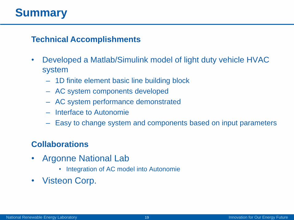
Summary
• AC use can account for significant portion of the energy used by LDV.
• Reducing AC energy use is essential to achieving the president’s goal of 1 million electric drive vehicles by 2015.
• Develop a Matlab/Simulink based model which is both flexible (to model various AC systems) and accurate.
• Interface AC model with Autonomie vehicle simulation tool, so that effects of AC use on vehicle efficiency can be modeled.
National Renewable Energy Laboratory Innovation for Our Energy Future18
DOE Mission Support
Approach
Summary
• Developed a Matlab/Simulink model of light duty vehicle HVAC system – 1D finite element basic line building block– AC system components developed– AC system performance demonstrated– Interface to Autonomie– Easy to change system and components based on input parameters
• Argonne National Lab• Integration of AC model into Autonomie
• Visteon Corp.
Technical Accomplishments
Collaborations
National Renewable Energy Laboratory Innovation for Our Energy Future19

Special thanks to:Lee SlezakAdvanced Vehicle Technology Analysis and EvaluationVehicle Technologies Program
David AndersonAdvanced Vehicle Technology Analysis and EvaluationVehicle Technologies Program
For more information:Presenter: Larry ChaneyNational Renewable Energy [email protected]
Task Leader: John RughNational Renewable Energy [email protected]
Contacts
National Renewable Energy Laboratory Innovation for Our Energy FutureNational Renewable Energy Laboratory Innovation for Our Energy Future20

Technical Backup Slides
National Renewable Energy Laboratory Innovation for Our Energy Future21

Pressure Drop in Refrigerant Lines
National Renewable Energy Laboratory Innovation for Our Energy Future22
The Darcy-Weisbach Equation:
From which the term used in the momentum equation:
The pipe friction factor for laminar flow (Re < 2300):
The pipe friction factor for turbulent flow (Re > 2300):
where e is the relative roughness of the pipe inner surface.(This latter equation is an explicit approximation formula for the well known Colebrook equation)

Heat Transfer Equations Currently Implemented
National Renewable Energy Laboratory Innovation for Our Energy Future23
Pipe wall to refrigerant:
where the film coefficient is calculated with the Dittus-Boelterequation:
Heat transfer from air to pipe wall:
where the film coefficient can be calculated with an equation valid on circular pipe placed in 90 degree cross-flow:
The actual coefficients C, m, n, can be modified for a particular geometry


![Melt Superheating on the Microstructure and Mechanical ... · Si alloys, by using superheating treatment, the primary sili-con grains were remarkably refined [17,18]. The reported](https://img.pdfslide.net/doc/110x75/5ed28a85af2f306b9a013ece/melt-superheating-on-the-microstructure-and-mechanical-si-alloys-by-using-superheating.jpg)


![Power hardware in the loop validation of fault ride ... · advantages over the HVAC transmission system [3–6]. The choice between a HVAC and a HVDC transmission system depends upon](https://img.pdfslide.net/doc/110x75/5ebf935af4163c04dc17b09f/power-hardware-in-the-loop-validation-of-fault-ride-advantages-over-the-hvac.jpg)