Embed Size (px)
Citation preview
02 février 2016
LE BARRAGE FAIT
PEAU NEUVE
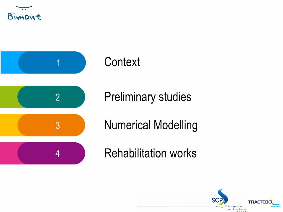
1 Context
2 Preliminary studies
3 Numerical Modelling
4 Rehabilitation works
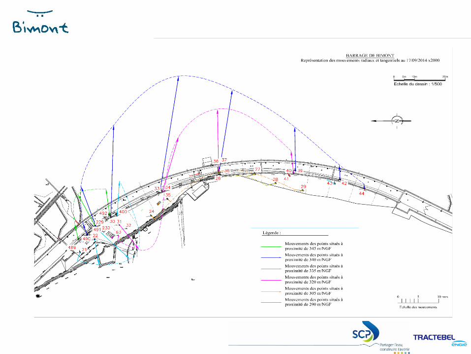
CONTEXT
LE BARRAGE FAIT PEAU NEUVE
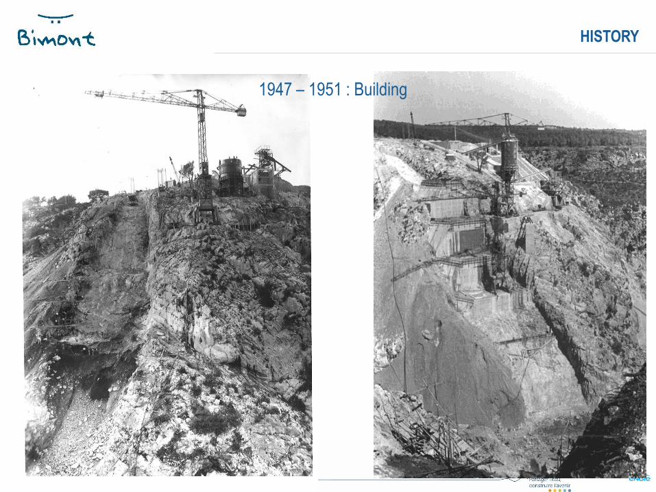
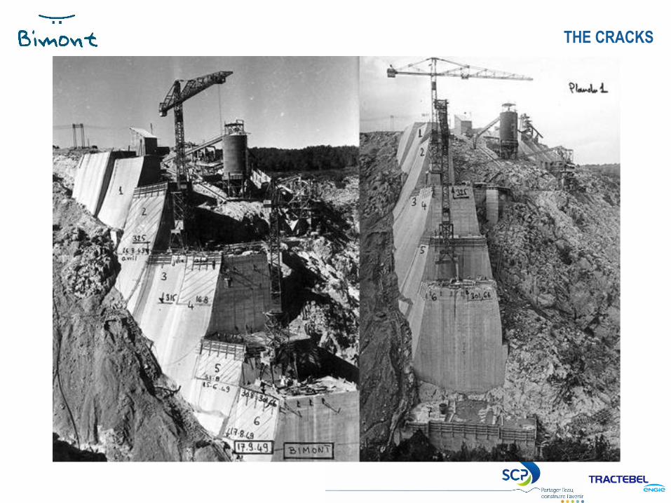
HISTORY
1947 – 1951 : Building
LE BARRAGE FAIT PEAU NEUVE
THE CRACKS
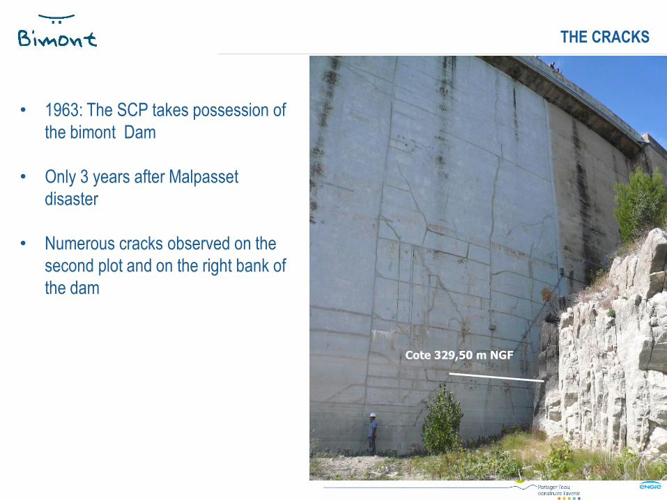
• 1963: The SCP takes possession of
the bimont Dam
• Only 3 years after Malpasset
disaster
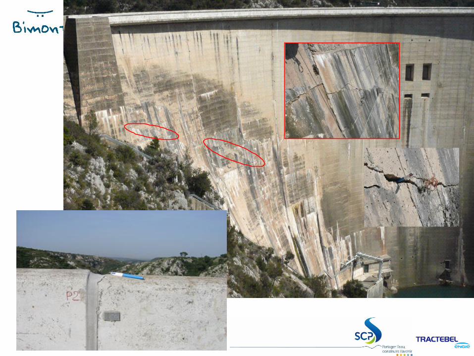
• Numerous cracks observed on the
second plot and on the right bank of
the dam
Cote 329,50 m NGF
Cote 329,50 m NGF
LE BARRAGE FAIT PEAU NEUVE
THE CRACKS
• The geology was first suspected.
• Numerous fields of investigations:
➢ Complementary geological studies
➢ Gallery cutted into the rock foundation of the second cantilever
➢ Additionnal monitoring instruments: 2 plumblines, fissurometers,
Topographic survey
➢ Mapping of the cracks network
➢ Several numerical models
A geological cause of the damages was rejected
THE CRACKS
LE BARRAGE FAIT PEAU NEUVE
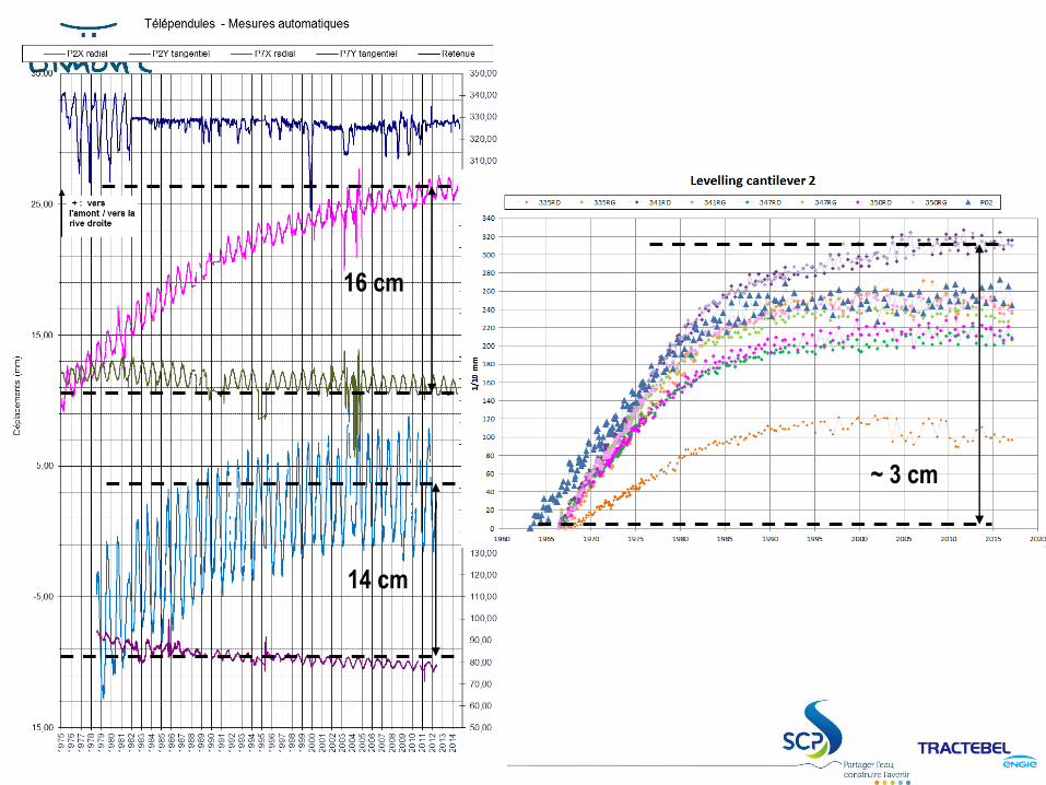
16 cm
14 cm
~ 3 cm
PRELIMINARY
STUDIES
LE BARRAGE FAIT PEAU NEUVE
PRELIMINARY STUDIES
LE BARRAGE FAIT PEAU NEUVE
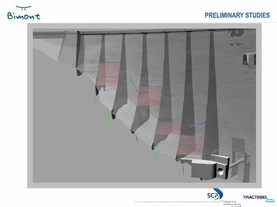
PRELIMINARY STUDIES
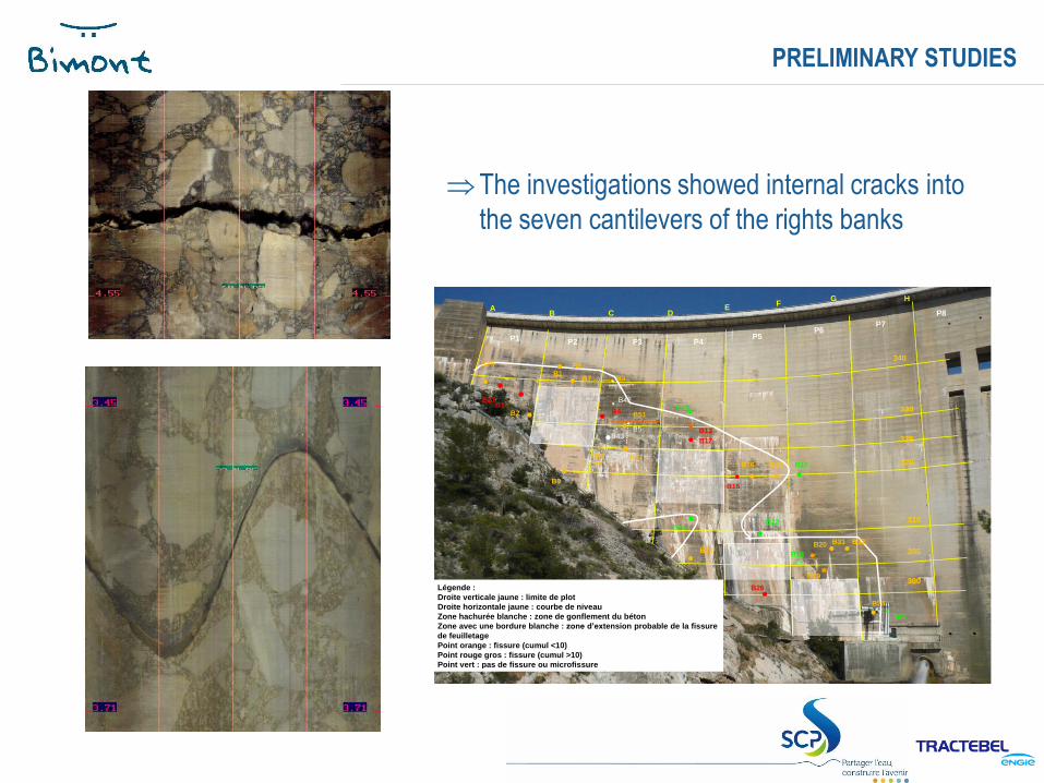
The investigations showed internal cracks into
the seven cantilevers of the rights banks
G
P1 P2 P3 P4 P5
P6 P7
P8 B A
C D E
F
340
330
325
320
310
300
B1 B3
B2 B4
B43
B42
B5
B6
B10
B7
B9
B12
B17
B14
B15
B11
B22
B21
B26
B18
B19
H
Légende :
Droite verticale jaune : limite de plot
Droite horizontale jaune : courbe de niveau
Zone hachurée blanche : zone de gonflement du béton
Zone avec une bordure blanche : zone d’extension probable de la fissure
de feuilletage
Point orange : fissure (cumul <10)
Point rouge gros : fissure (cumul >10)
Point vert : pas de fissure ou microfissure
B16
B13
B20
B24
B25
B8
B51
B27
B28
B29
B31
B30
305
B32
LE BARRAGE FAIT PEAU NEUVE
LAST LABORATORY TEST
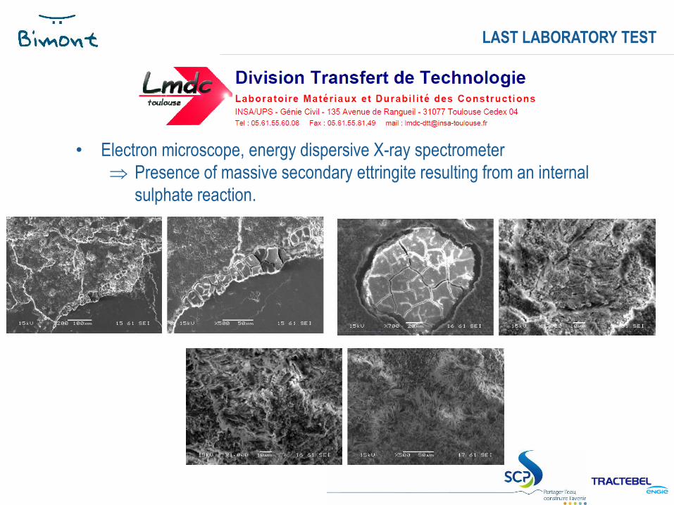
• Electron microscope, energy dispersive X-ray spectrometer
Presence of massive secondary ettringite resulting from an internal
sulphate reaction.
LE BARRAGE FAIT PEAU NEUVE
LAST LABORATORY TEST
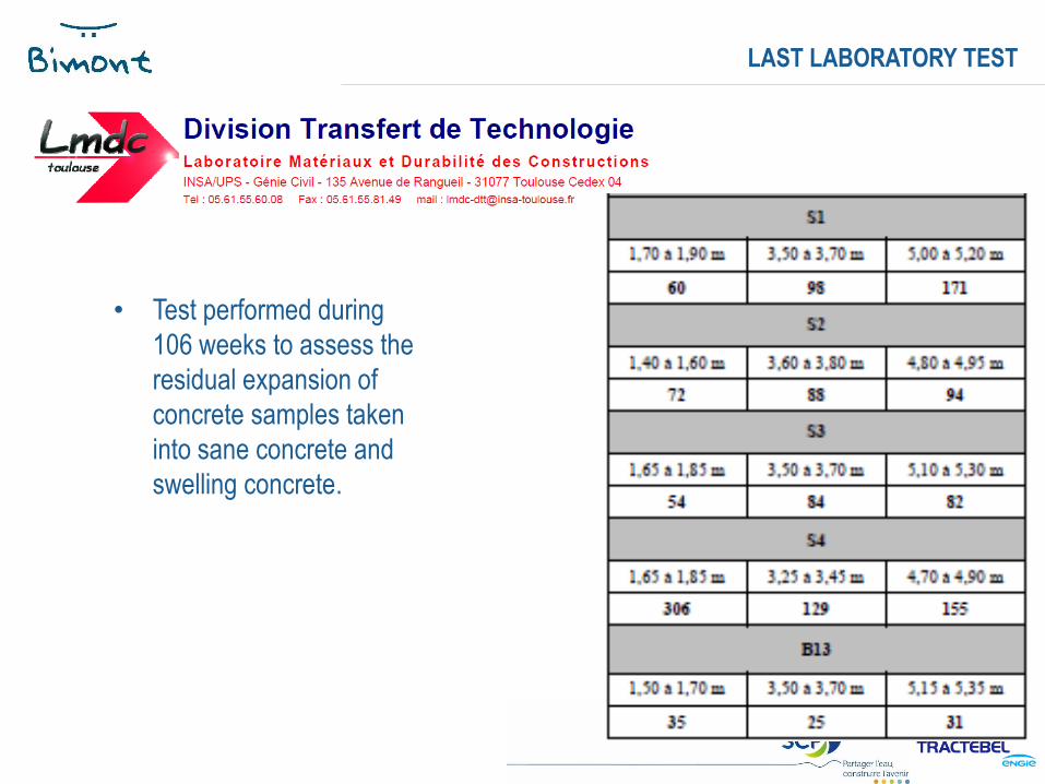
• Test performed during
106 weeks to assess the
residual expansion of
concrete samples taken
into sane concrete and
swelling concrete.
NUMERICAL
MODELLING
10 juin 2010
Barrage de Bimont 17G
P
1P
2
P
3
P
4
P
5
P
6
P
7
P
8
BA
C D EF
340
33
0
32
0
31
0
300
H
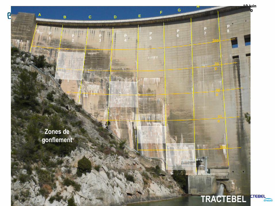
Zones de
gonflement
TRACTEBEL

10 juin 2010
18
Barrage de BimontG
P
1P
2
P
3
P
4
P
5
P
6
P
7
P
8
BA
C D EF
340
33
0
32
0
31
0
300
H
Zones de
gonflement
TRACTEBEL
10 juin 2010
19
Barrage de BimontG
P
1P
2
P
3
P
4
P
5
P
6
P
7
P
8
BA
C D EF
340
33
0
32
0
31
0
300
H
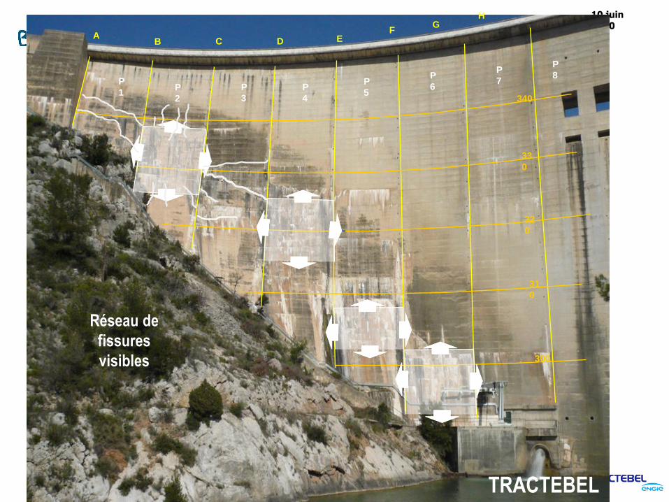
Réseau de
fissures
visibles
TRACTEBEL
20
Barrage de BimontG
P
1P
2
P
3
P
4
P
5
P
6
P
7
P
8
BA
C D EF
340
33
0
32
0
31
0
300
H
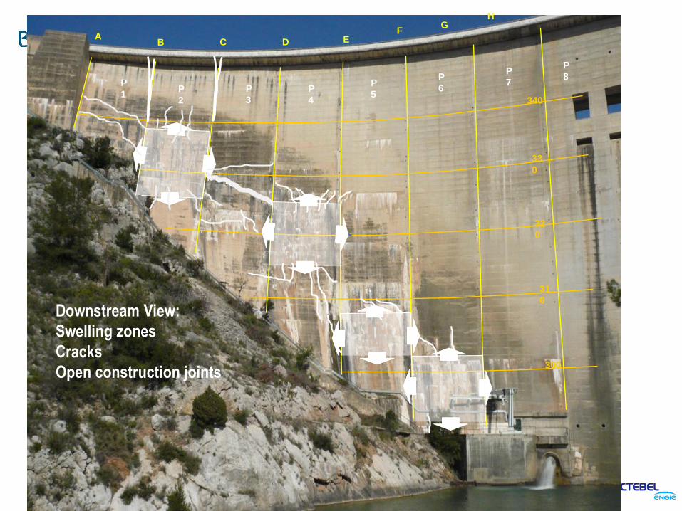
Downstream View:
Swelling zones
Cracks
Open construction joints
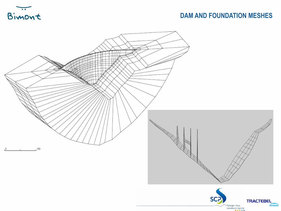
DAM AND FOUNDATION MESHES
2
2
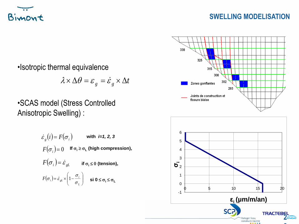
•Isotropic thermal equivalence
•SCAS model (Stress Controlled
Anisotropic Swelling) :
tgg
ig Fi
0iF
gLiF
L
i
gLiF
1
with i=1, 2, 3
If i L (high compression),
if i 0 (tension),
si 0 i L
-1
0
1
2
3
4
5
6
0 5 10 15 20
σi
εi (µm/m/an)
SWELLING MODELISATION
23
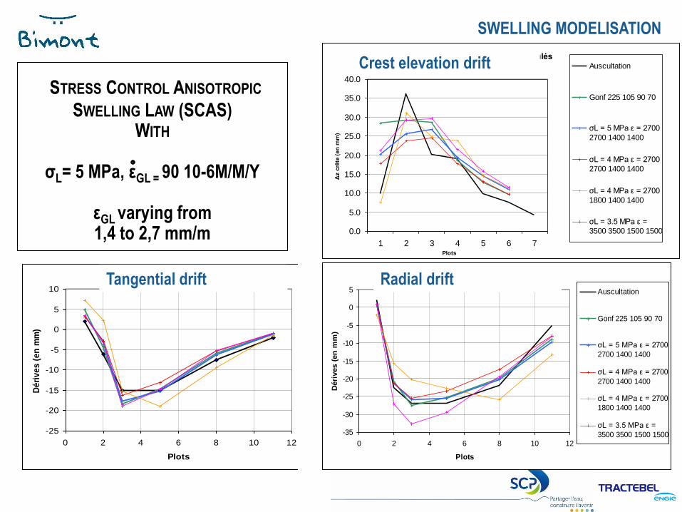
STRESS CONTROL ANISOTROPIC
SWELLING LAW (SCAS) WITH
σL= 5 MPa, εGL = 90 10-6M/M/Y
εGL varying from1,4 to 2,7 mm/m
Comparaison des Δz crête de nivellement calculés
0.0
5.0
10.0
15.0
20.0
25.0
30.0
35.0
40.0
1 2 3 4 5 6 7Plots
Δz c
rête
(en
mm
)
Auscultation
Gonf 225 105 90 70
σL = 5 MPa ε = 2700
2700 1400 1400
σL = 4 MPa ε = 2700
2700 1400 1400
σL = 4 MPa ε = 2700
1800 1400 1400
σL = 3.5 MPa ε =
3500 3500 1500 1500
Dérives radiales
-35
-30
-25
-20
-15
-10
-5
0
5
0 2 4 6 8 10 12
Plots
Déri
ves (
en
mm
)
Auscultation
Gonf 225 105 90 70
σL = 5 MPa ε = 2700
2700 1400 1400
σL = 4 MPa ε = 2700
2700 1400 1400
σL = 4 MPa ε = 2700
1800 1400 1400
σL = 3.5 MPa ε =
3500 3500 1500 1500
Dérives tangentielles
-25
-20
-15
-10
-5
0
5
10
0 2 4 6 8 10 12
Plots
Dé
riv
es
(e
n m
m)
Auscultation
Gonf 225 105 90 70
σL = 5 MPa ε = 2700
2700 1400 1400
σL = 4 MPa ε = 2700
2700 1400 1400
σL = 4 MPa ε = 2700
1800 1400 1400
σL = 3.5 MPa ε =
3500 3500 1500 1500
SWELLING MODELISATION
Tangential drift Radial drift
Crest elevation drift
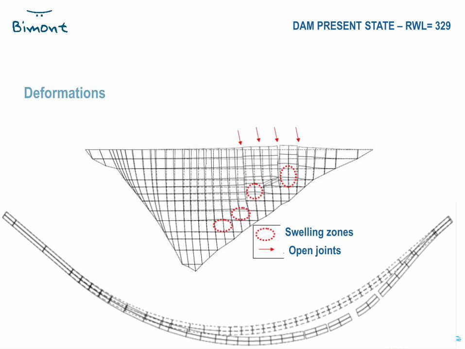
Deformations
DAM PRESENT STATE – RWL= 329
Swelling zones
Open joints
25
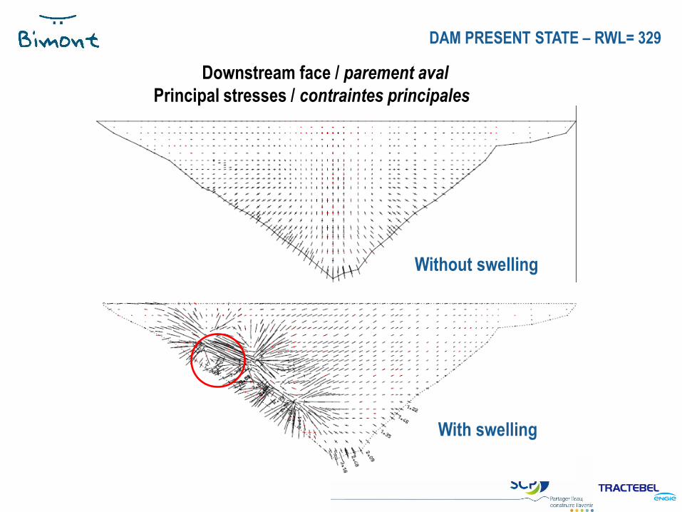
Without swelling
With swelling
Downstream face / parement aval
Principal stresses / contraintes principales
DAM PRESENT STATE – RWL= 329
2
6
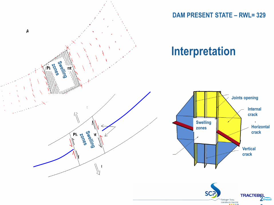
Interpretation
DAM PRESENT STATE – RWL= 329
Swelling
zones
Joints opening
Internal
crack
Horizontal
crack
Vertical
crack
2
7
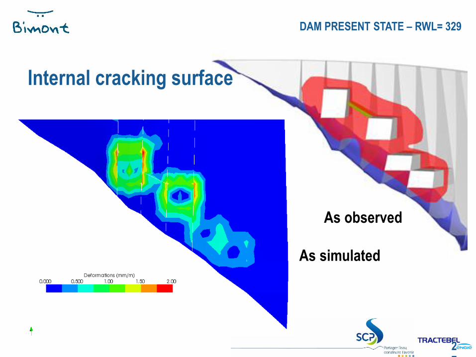
Internal cracking surface
DAM PRESENT STATE – RWL= 329
As observed
As simulated
REHABILITATION
WORKS
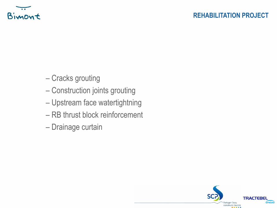
– Cracks grouting
– Construction joints grouting
– Upstream face watertightning
– RB thrust block reinforcement
– Drainage curtain
REHABILITATION PROJECT
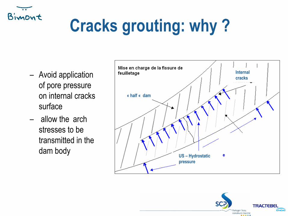
Cracks grouting: why ?
Internal
cracks
« half « dam
US – Hydrostatic
pressure
– Avoid application
of pore pressure
on internal cracks
surface
– allow the arch
stresses to be
transmitted in the
dam body
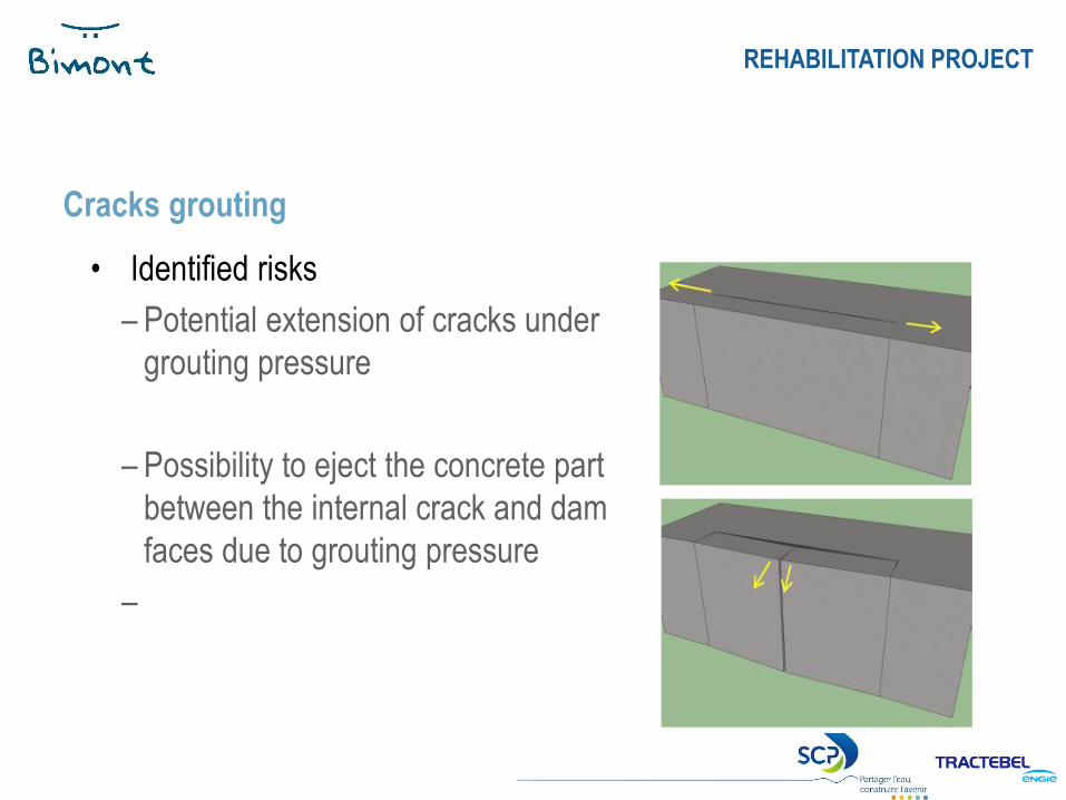
• Identified risks
– Potential extension of cracks under
grouting pressure
– Possibility to eject the concrete part
between the internal crack and dam
faces due to grouting pressure
–
Cracks grouting
REHABILITATION PROJECT
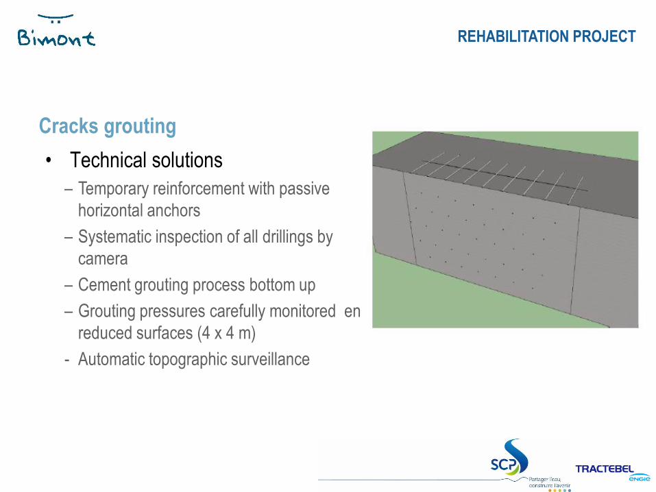
• Technical solutions
– Temporary reinforcement with passive
horizontal anchors
– Systematic inspection of all drillings by
camera
– Cement grouting process bottom up
– Grouting pressures carefully monitored en
reduced surfaces (4 x 4 m)
- Automatic topographic surveillance
Cracks grouting
REHABILITATION PROJECT
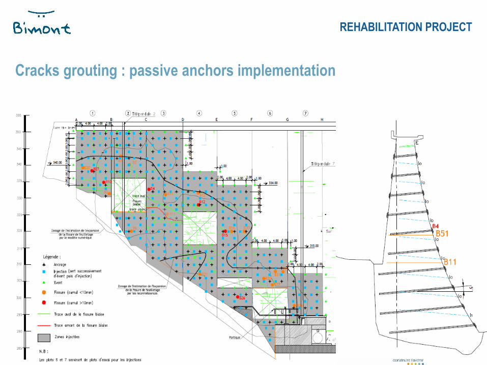
Cracks grouting : passive anchors implementation
REHABILITATION PROJECT
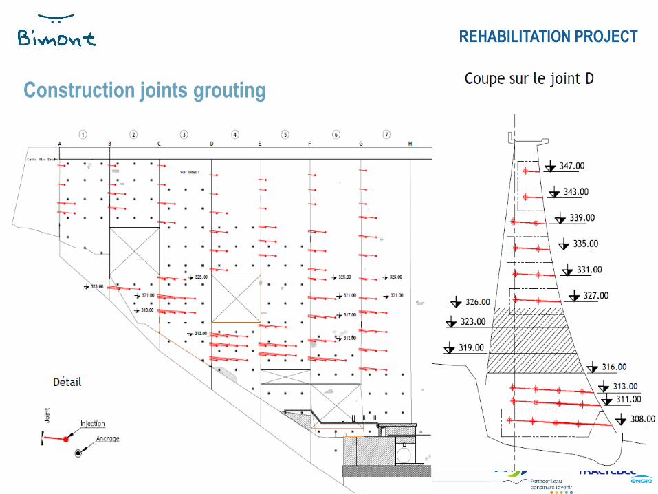
Construction joints grouting
REHABILITATION PROJECT
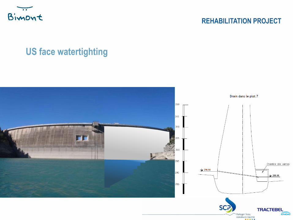
US face watertighting
REHABILITATION PROJECT
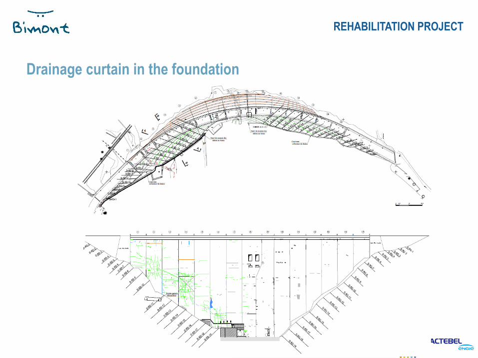
Drainage curtain in the foundation
REHABILITATION PROJECT
LE BARRAGE FAIT PEAU NEUVE
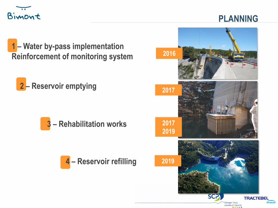
PLANNING
4 – Reservoir refilling
2016
2017
2019
2017
2019
1 – Water by-pass implementation
Reinforcement of monitoring system
2 – Reservoir emptying
3 – Rehabilitation works
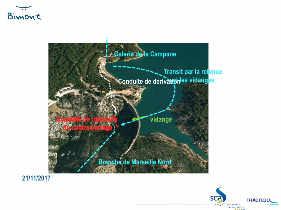
21/11/2017
Les travaux préparatoires : la dérivation
Galerie de la Campane
Branche de Marseille Nord
vidange
Conduite de dérivation
Transit par la retenue
et les vidanges
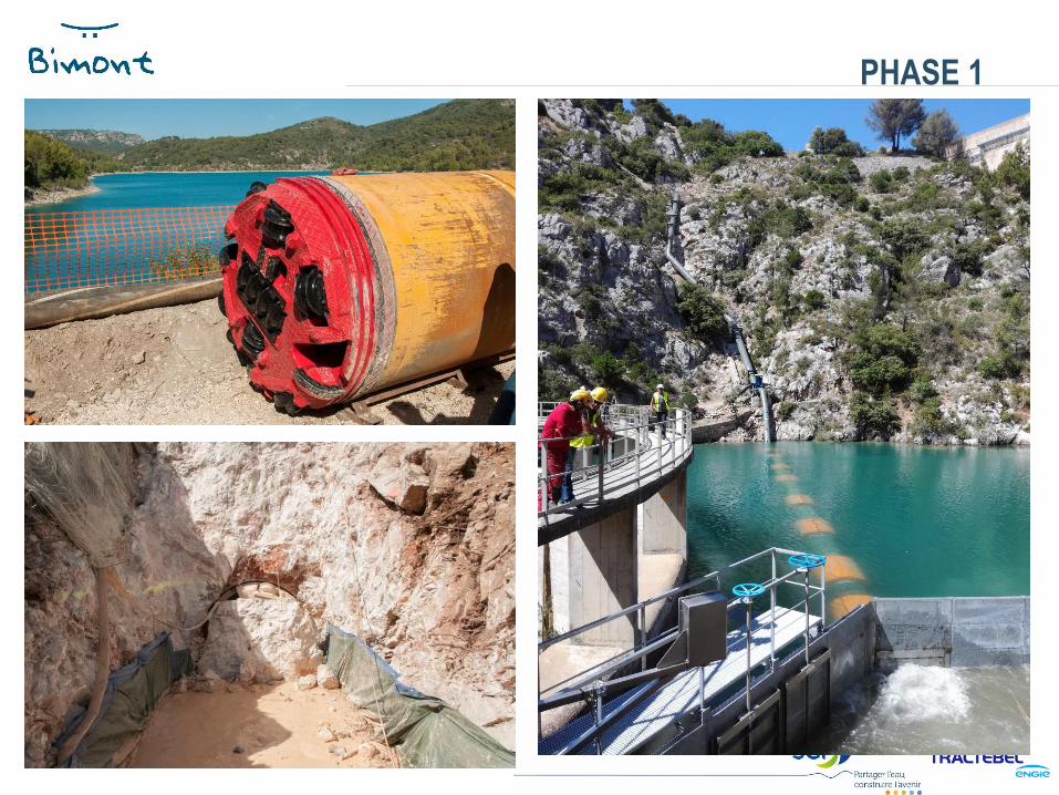
LE BARRAGE FAIT PEAU NEUVE
PHASE 1
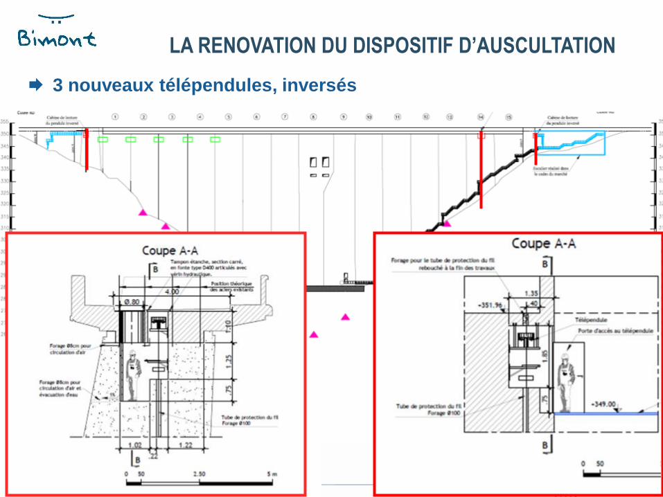
3 nouveaux télépendules, inversés
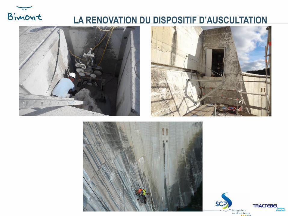
LA RENOVATION DU DISPOSITIF D’AUSCULTATION
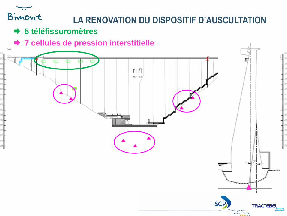
5 téléfissuromètres
7 cellules de pression interstitielle
LA RENOVATION DU DISPOSITIF D’AUSCULTATION
LE BARRAGE FAIT PEAU NEUVE
LA RENOVATION DU DISPOSITIF D’AUSCULTATION
THANK YOU FOR YOUR
ATTENTION