Embed Size (px)
Citation preview
58640 State Road 15 Phone: 574-533-0337
www.p-e-i.com
Goshen, IN 46528 -Fax: 574-533-9736 -
Progressive Engineering Inc.
2017-326
L.E. O NSON PRODUCTS
ASTM E330 Positive Uniform Load Teston 1500 Series Pocket Door Frame(Horizontal) on 2x4 Lumber Framing
2/16/2017
This test report contains sixteen (16) pages, including the cover sheet. Any additions to, alterations of, or unauthorized use of excerpts form this report are expressly forbidden.

1. TITLE
2. O ECTI E
3. TESTED FOR
. TESTIN OR ANI ATION
5. TESTIN PERSONNEL
Director of Testing - Jason R. HoldemanProject Manager - Jacob BontragerTechnician - Chris Stutzman
. REFERENCE STANDARDS
. TEST E UIPMENT
A.B.C.D.E.
. TEST SPECIMEN
A.
B.
Elkhart, IN 46516
Progressive Engineering Inc.58640 State Road 15Goshen, IN 46528www.p-e-i.com
ASTM E330 Positive Uniform Load Test on 1500 Series Pocket Door Frame (Horizontal) on 2x4Lumber Framing
To verify that the provided interior wall test specimen meets a 5 PSF uniform design pressure withless than "/180 deflection and achieve a minimum of 2.5 times the design pressure.
This test report pertains only to the specimens tested. It remains the sole responsibility of themanufacturer to provide a product consistent to that which was tested.
L.E. Johnson Products, Inc.2100 Sterling Ave.
See IAS Evaluation Report TL-178 for ISO 17025 Accreditation.
Test was witnessed by Stephen Johnson with L.E. Johnson Products.
ASTM E330 1 Standard Test Method For Structural Performance of Exterior Windows, Doors,Skylights and Curtain Walls by Uniform Static Air Pressure Difference
Water manometer (PEI No. 076)Pressure Transducer (PEI No. 970)Vacuum test fixture (PEI No. 372)Three (3) 4" linear transducers (PEI Nos. 890, 891 and 892)Data Acquisition System (PEI No. 523)
Pocket Door Frame
1500 Series Pocket Door Frame - Three (3) boxes each containing a 153068PF PocketDoor Frame assembly were supplied by L.E. Johnson Products and were manufactured on01/13/17, 02/02/17, and 12/22/16. The assembly consisted of a steel studs with lumberinserted, a header, brackets, and other hardware.
The gypsum panel was 1/2" thick locally purchased drywall.
Gypsum Panel
2 of 16 PEI Report No. 2017-326

C.
D.1.
2.
3.
4.
. TEST SPECIMEN CONSTRUCTION
A.
B.
C.
D.
10. TEST SET UP
The Pocket Wall Material provided in the kit, including the header, end plate, steel split studs,and brackets were assembled as per the provided client instructions. One set of slip studswas installed at the center of the 36" opening, and the other set of split studs was installed onthe far right side, aka "Door Side". The split studs were nailed to the header with two (2) 6d x2" long Bright Common nails per stud. The bottom of the slip studs attached to a bracket,which was screwed to the 2x4 frame with two (2) #8 x 1-1/2" long washerhead wood screws.
Gypsum to Frame - #6 x 1" long Bugle Head drywall screw, with an average headdiameter of .323" and an average shank diameter of .146".
A 2x4 frame with a rough opening of 36" x 84-1/4" was assembled using two (2) #8 x 3"washerhead screws per stud end. This frame simulated the 2x4 framing of an existing wall, inwhich the 1500 Series Pocket Door Frame would be installed. The left side of the frame is the"Wall Side" and the right side of the frame is the side in which the door slides, aka "DoorSide". The scope for this testing covers the wall which hides the door, not the walkway, so thewalkway is not incorporated into the frame.
A 1/2" x 37-1/2" x 87-1/4" sheet of the gypsum was laid on the pre-assembled frame. Thegypsum was installed on the 2x4 framing on the "Wall Side" of the frame, over to the split studof the "Door Side" of the frame. A deflection measurement was taken to determine how muchthe test sample deflected when the weight of the gypsum was applied to the split stud. Thiswas recorded as the "Dead Load'.
A test sample was placed in a test fixture with the gypsum side facing up. The 2x4 frame wassupported with a total of six (6) legs. A 2 mil thick piece of plastic sheeting was loosely draped overthe wall frame. The edges of the polyethylene sheeting were taped to the test fixture. Three (3)linear transducers were positioned on the "Door Side" of the frame (point of greatest deflection)relative to the test fixture; one (1) on the corner of the header plate, one (1) on the corner of thebottom plate and the third at the center of the split stud.
Frame 2 x 4 No. 2 Grade SPF Lumber with an average moisture content of 12%.
Fasteners
A total of three (3) specimens were constructed by PEI personnel, with vertically orientedgypsum. Vertical indicates that the long edge of the panel is parallel to the studs. Thefasteners were placed 12" o.c. around the perimeter and 12" o.c. along the center of the fieldstuds with the heads set flush or slightly below the board surface. The perimeter fastenerswere spaced 3/4" in from the edge of the sheathing. See the attached drawing for details.
Wooden Frame - #8 x 3" long washerhead screws.
Split Stud to Header - 6d 2" Bright Common nails.
Split Stud to Bottom Plate / Floor - #8 x 1-1/2" long washerhead wood screw.
3 of 16 PEI Report No. 2017-326
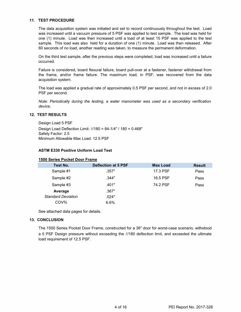
11. TEST PROCEDURE
12. TEST RESULTS
Minimum Allowable Max Load: 12.5 PSF
ASTM E330 Positive Uniform Load Test
1500 Series Pocket Door FrameResultPass
Pass
Pass
13. CONCLUSION
Sample #3
Max Load
COV%
See attached data pages for details.
.024"6.6%
AverageStandard Deviation
.357"
.344"
.401"
17.3 PSF
The 1500 Series Pocket Door Frame, constructed for a 36" door for worst-case scenario, withstooda 5 PSF Design pressure without exceeding the "/180 deflection limit, and exceeded the ultimateload requirement of 12.5 PSF.
Safety Factor: 2.5
Design Load 5 PSF
Deflection at 5 PSF
16.5 PSF
74.2 PSF.367"
Test No.Sample #1
Sample #2
The data acquisition system was initiated and set to record continuously throughout the test. Loadwas increased until a vacuum pressure of 5 PSF was applied to test sample. The load was held forone (1) minute. Load was then increased until a load of at least 15 PSF was applied to the testsample. This load was also held for a duration of one (1) minute. Load was then released. After60 seconds of no load, another reading was taken, to measure the permanent deformation.
Failure is considered, board flexural failure, board pull-over at a fastener, fastener withdrawal fromthe frame, and/or frame failure. The maximum load, in PSF, was recovered from the dataacquisition system.
The load was applied a gradual rate of approximately 0.5 PSF per second, and not in excess of 2.0PSF per second.
Note: Periodically during the testing, a water manometer was used as a secondary verificationdevice.
Design Load Deflection Limit: "/180 = 84-1/4" / 180 = 0.468"
On the third test sample, after the previous steps were completed, load was increased until a failureoccurred.
4 of 16 PEI Report No. 2017-326

Date 2/16/2017Client L.E. Johnshon Products
S ecimen 1500 Series Pocket Door Frame Tem erature 70 Fumidit 15%
oard T ickness 1/2"oard Orientation ertical
Fastener S acing 12" per x 12" fieldFastener T e #6 x 1" Screw
all eig t 84-1/4"Dead Load 1.2 PSF
Defl. Re uirement 0.468" 5 PSFSafet Factor 2.5
Load Re uirement
Test Sam le 1
ottom Plate
Center of Stud To Plate
Net Deflection
0.0 -- 0.000 0.000 0.000 0.000Dead Load 00:00.0 0.000 0.187 0.000 0.000
5.2 00:34.3 0.001 0.357 0.000 0.3576.6 01:48.2 0.002 0.476 0.000 0.47515.1 02:20.3 0.010 1.197 0.000 1.19217.3 02:34.1 0.014 1.402 0.002 1.39416.9 03:42.2 0.014 1.405 0.003 1.397
Dead Load 04:53.0 0.012 0.466 0.008 0.456
Failure
1/2" x 37-1/2" x 84-1/4" gypsum panel screwed to a Pocket Panel Door assembly, with studs spaced 18" o.c.
1 .3 PSF
Pre Load12.5 PSF N/A N/A
Deflection inc es
Target Ultimate Load
Load in PSF
12.5 PSF
Max Load
Taken after 60 seconds with no load
Gypsum Panel Not AppliedWith Gypsum Panel Attached to frame
Test Time MM SS.0 Comments O servations
No failure occurred. Load was released after 15 PSF load was held for at least 60seconds.
Progressive Engineering Inc.ASTM E330 Negative ind Load
Test Conditions
Linear Transducer LocationLVDT's set on the door opening side as indicated below.
Max Load
5 of 16 PEI Report No. 2017-326

Date 2/16/2017Client L.E. Johnshon Products
S ecimen 1500 Series Pocket Door Frame Tem erature 70 Fumidit 15%
oard T ickness 1/2"oard Orientation ertical
Fastener S acing 12" per x 12" fieldFastener T e #6 x 1" Screw
all eig t 84-1/4"Dead Load 1.2 PSF
Defl. Re uirement 0.468" 5 PSFSafet Factor 2.5
Load Re uirement
Test Sam le 2
ottom Plate
Center of Stud To Plate
Net Deflection
0.0 -- 0.000 0.000 0.000 0.000Dead Load 00:00.0 0.000 0.187 0.000 0.000
5.1 00:10.7 0.001 0.344 0.000 0.3446.5 01:23.3 0.003 0.459 0.000 0.45812.8 01:43.8 0.012 0.677 0.001 0.67016.5 02:24.3 0.019 0.771 0.010 0.75616.1 03:15.5 0.019 0.786 0.011 0.771
Dead Load 04:36.1 0.007 0.347 0.006 0.340
Failure
Progressive Engineering Inc.ASTM E330 Negative ind Load
Test Conditions
1/2" x 37-1/2" x 84-1/4" gypsum panel screwed to a Pocket Panel Door assembly, with studs spaced 18" o.c.
12.5 PSF
Target Ultimate Load Pre Load Linear Transducer Location12.5 PSF N/A N/A LVDT's set on the door opening side as indicated below.
Load in PSF
Test Time MM SS.0
Deflection inc es
Comments O servationsGypsum Panel Not Applied
With Gypsum Panel Attached to frame
Max Load
Taken after 60 seconds with no load
Max Load 1 .5 PSF
No failure occurred. Load was released after 15 PSF load was held for at least 60seconds.
6 of 16 PEI Report No. 2017-326

Date 2/16/2017Client L.E. Johnshon Products
S ecimen 1500 Series Pocket Door Frame Tem erature 70 Fumidit 15%
oard T ickness 1/2"oard Orientation ertical
Fastener S acing 12" per x 12" fieldFastener T e #6 x 1" Screw
all eig t 84-1/4"Dead Load 1.2 PSF
Defl. Re uirement 0.468" 5 PSFSafet Factor 2.5
Load Re uirement
Test Sam le 3
ottom Plate
Center of Stud To Plate
Net Deflection
0.0 -- 0.000 0.000 0.000 0.000Dead Load 00:00.0 0.000 0.187 0.000 0.000
5.0 00:12.5 0.003 0.403 0.002 0.40112.8 01:42.4 0.021 1.009 0.006 0.99616.8 03:00.8 0.033 1.312 0.006 1.292
Dead Load 04:22.3 0.008 0.381 -0.002 0.37874.2 05:23.7 N/A N/A N/A N/A
Failure
Linear Transducer Location
Test Time MM SS.0
Deflection inc es
Comments O servations
Progressive Engineering Inc.ASTM E330 Negative ind Load
Test Conditions
1/2" x 37-1/2" x 84-1/4" gypsum panel screwed to a Pocket Panel Door assembly, with studs spaced 18" o.c.
12.5 PSF
Target Ultimate Load Pre Load
Gypsum Panel Not AppliedWith Gypsum Panel Attached to frame
12.5 PSF N/A N/A LVDT's set on the door opening side as indicated below.
Load in PSF
Taken after 60 seconds with no load
Ultimate Load .2 PSF
The gypsum panel failed in flexure between the split stud and 2x4 frame.
7 of 16 PEI Report No. 2017-326

84.2
5
18.0
018
.00
SPLI
T ST
UD
SPLI
T ST
UD
POC
ET D
OO
RH
EAD
ERG
PSU
M P
ANEL
#8
1" D
RW
ALL
SCR
EW
24
LUM
BER
FR
AME
(NO
T AT
TAC
HED
TO
SPL
IT S
TUD
)
DEF
LEC
TIO
N M
EASU
REM
ENT
LOC
ATIO
N (
3)
WAL
L SI
DE
DO
OR
SID
E
WAL
L SI
DE
DO
OR
SID
E
24
FRAM
E
ww
w.p
-e-i
.co
m
P rog
ress
ive
Fa
x (5
74
) 5
33
-97
36
nc
.
58
64
0 S
tate
Ro
ad
15
Go
she
n, I
N 4
65
28
Ph
on
e (
57
4)
53
3-0
33
7IE ng
ine
eri
ng
JOB
NO
.
DW
G. N
O.
SCAL
E:
DAT
E:
DW
N. B
:
TITL
E:
REV
ISED
ON
:C
LIEN
T:Th
is d
raw
ing
and
all i
nfor
mat
ion
cont
aine
d he
rein
is th
e pr
oper
ty o
fPR
OG
RES
SIVE
EN
GIN
EER
ING
,IN
C. a
nd is
not
to b
e re
prod
uced
with
out t
he w
ritte
n pe
rmis
sion
of
assu
mes
no
resp
onsi
bilit
y fo
r una
utho
rized
use
of th
is d
raw
ing.
Pei. Pei
J. B
ON
TRAG
ER
2/16
/201
7
THIS
DR
AWIN
G IS
A P
ART
OF
TEST
REP
OR
T N
O. 2
017-
326
B1
L.E.
JO
HN
SON
PRO
DU
CTS
POC
ET D
OO
RTE
ST S
PEC
IMEN
8 of 16 PEI Report No. 2017-326

1500 Series Pocket Door Frame
INSERT PICTURE HERE (2.72" H. 3.63" W.)
Test Sample #3 Failure Test Sample #3 Failure
Typical Sample After Testing
INSERT PICTURE HERE (2.72" H. 3.63" W.) INSERT PICTURE HERE (2.72" H. 3.63" W.)
Test Sample #1 After Testing
Progressive Engineering Inc.
INSERT PICTURE HERE (2.72" H. 3.63" W.) INSERT PICTURE HERE (2.72" H. 3.63" W.)
Typical Test Frame Typical Test Setup
9 of 16 PEI Report No. 2017-326

Pocket Door Hardware (Header, Slit Stud Bracket, Split Studs
Top Plate End Plate
Progressive Engineering Inc.
2.221" wide x 2.501" long x 3.499" x 2.246" x 0.073" thick end plate.
1.781" wide x 0.762" deep x 0.49" thick steel
1.786" wide x 1.260" tall x0.058" thick aluminum channel attached to 2.003" x 0.757" lumber. Together these form the top plate
3.501" long x 1.629" wide x .972" tall x 0.073" thicksplit stud bracket.
10 of 16 PEI Report No. 2017-326

Progressive Engineering Inc.
Connection to Top Plate
Connection to Floor
all ide oor ide
all ide oor ide
Two 2 8 x 1 1 2" long washerhead wood screws
Two 2 6d 2" right ommon nails per stud end.our 4 8 x 1 1 2" long
washerhead wood screws
11 of 16 PEI Report No. 2017-326

Progressive Engineering Inc.
APPENDIX
L.E. O NSON PRODUCTS2017-326
12 of 16 PEI Report No. 2017-326

www.johnsonhardware.com 1500 SERIESPOCKET DOOR FRAME
IN1500PD L.E. O NSON PRODUCTS INC. 2100 STERLIN A E. EL ART IN USA 51 5 2 3 5 Rev 7/16
R
1500 SERIES SET NUM ERS AND SI ES152068PF FOR 1-24" (609mm) 80"(2,03m) Door, Puerta, Porte152468PF FOR 1-28" (710mm) 80" (2,03m) Door, Puerta, Porte152668PF FOR 1-30" (761mm) 80" (2,03m) Door, Puerta, Porte
152868PF FOR 1-32" (812mm) 80" (2,03m) Door, Puerta, Porte153068PF FOR 1- 36" (913mm) 80" (2,03m) Door, Puerta, Porte
1500 MADE FOR 2 STUD ALLS
All purpose frames, marked to cut to shorter lengths.Marcos universales, marcados para ser cortados a longitudes menores.
Montants usage multiple, marqu s pour tre coup s plus court.
NOTE Instructions are for a 80" (2,03m) door, if door is shorter, lower header and cut bottom ends of Split Studs, if door is taller than 80" (2m), order longer Split Studs and raise header.
NOTA Las instrucciones son para una puerta de 2,03m. Si la puerta es mas corta, baja la cabecera y corte los extremos de abajo de las jambas divididas. Si la puerta es m s alta que 2,03m, ordene piezas verticales m s largas y suba la cabecera.NOTE Les instructions se r ferrent la porte de 2,03m, Si la porte est plus petite, abaissez le guide et coupez les extr mit s
des montants de s paration. Si la porte est haute que 2,03m, commandez des montants plus longs et rehaussez le guide.
CONSTRUCT ROU OPENIN Header must be S UARE and PLUM with studs and LE EL. Minimum Height is 84 1/2" (2,14m) width is 2 Door width plus 1" (25mm).1
2
3 Sna a chalk line on floor even with side jambs.
CONSTRU A LA A ERTURA PRELIMINAR. La cabeceradebe de estar en ESCUADRA y A PLOMO con los montantesy a NI EL. La Altura Minima es de 2,14m, el Ancho es de2 Ancho de Puerta mas 25mm.CONSTRUISE L OU ERTURE RUTE. Le guide doit treperpendiculaire et d'aplomb avec les montants ainsi qu' niveau.La hauteur minimale est de 2,14m. La largeur correspond 2 porte plus 25mm.
Mar ue una linea con un cordel entizado en el pisoque concuerde con las jambas laterales.
Trace craie une ligne au sol parall le aux montants lat raux.
CON ER IN DOORS RE UIRE T O FRAMES AND T E 1555 CON ER IN DOOR IT.
NAILCLAVOCLOU NAIL
CLAVOCLOU
CHAL LINELINEA DE TI A
LIGNE A LA CRAIE
Frames for Doors up to 60" (1.27m) wide and 108" (2.74m) high are available.Hay marcos disponibles para Puertas de hasta 1,27m de ancho 2,74m de alto.
Des montants pour Portes jusqu'a 1,27m en largeur et 2,74m en hauteur sont disponibles.
NAIL ON CENTERCLAVO EN EL CENTRO
CLOU AU CENTRE1/8" 3.2mm
Measure up from finished floor 80-3/4" (2.05m) or from sub-floor to 81-1/2" (2.07m). This will give 3/4" (19mm) to 1-1/2" (38mm) clearance under door. Mark each roughstud and drive a flat head nail on center, leaving 1/8" (3mm)protuding. Frame eader end rackets ill rest on t ese nails .
Mida 2.05m desde el piso terminado 2.07m desde el sub-piso.Esto dar una separaci n de 19mm hasta 38mm debajode la puerta. Marque cada montante y clave un clavo decabeza plana en el centro de cada una, dejando 3mm afuera,Los so ortes de los extremos de la ca ecera del marco
se a o aran en estos clavos .Mesure 2,05m partir du sol fini ou bien 2,07m partir du sousplancher. Ce qui va donner un jeu de 19mm 38mm sous la porte.Marquez chaque montant et enfoncez un clou t te plate au centre,en laissant d passer 3mm. (Les croc ets du linteau re oserontsur ces clous .
With 1-3/4" (45mm) Doors, use 1575 Adapter itPara puertas de 45mm, use el Adaptador Modelo 1575
Avec les portes de 45mm, utillsez le it Adapteur r f. 1575
IMPORTANT
INSTALL IDEO
13 of 16 PEI Report No. 2017-326

Slip slots in Frame Header End Plates over nails in rough studs. LEVEL HEADER. Set nails and drive nails through remaining holes in end plates. (If you have the 2/6" (761mm) or Universal Frameand using another size door, see cutting instructions on page 4.)Encaje la ranuras que estan en las Placas de los Extremos de laCabecera del Marco en los clavos que estan en los montantes.Alinee los clavos y clavelos en los orificios restantes en las placasde los extremos. (Si usted tiene el Marco de 761mm o el MarcoUniversal y esta usando puerta de otro tama o, vea las instruccionesde corte en la p gina 4.)Glissez les encoches des extr mit s du linteau sur les clous fix sdans les montantes bruts. Mettez le guide niveau. Positionnez lesclous et enfoncez les au travers des trous restants dans les plaquesdes extr mit s. (Si vous avez le montant universel ou de 761mm etutilisez une dimension de porte differ rente, r f rez vous aux intructionsde coupe page 4.)
5 Note If using 1 3 5mm door use 15 5 Ada ter it.Slip fingers of Floor Plate into Split Studs as shown.
Butt Split Studs against header nailer and nail into place. Nailother Split Studs midway in "Pocket" opening. Plumb Split Studsbetween chalk lines and nail to floor. (On masonry, use industrialadhesive or Tapcon fasteners.)(Nota: Si esta usando una puerta de 45mm, use el AdaptadorModelo 1575). Encaje las aletas de la Placa del Piso en lasJambas Divididas tal como se muestra. Una a tope la jambadividida contra el List n para Clavar de la Cabecera y clavelaen su lugar. Clave la otra jamba divididia en la mitad de laabertura de la "Cavidad". Alinee verticalmente las jambas divididasntre la linea de tiza y clavelos al piso. (En el caso de mamposter a,use un adhesivo de tipo industrial o sujetadores Tapcon.)(Note: Si vouz utilisez la porte de 45mm, utilisez le kit adapteurr f. 1575) Ins rez, comme indiqu , les doigts des plaquesde sol dans les montants de s paration. Calez le montantde s paration contre le linteau et clouez en place. Clouez l'autremontant de s paration au milieu de l'ouverture "de poche". Mettezd'aplomb les montants entre les lignes trac es la craie et clouez au sol.(Sur de la maconnerie, utilisez un adh sif industriel ou de boulons Tapcon.)
Apply desired wall material. Wall material is brought clear to edge of opening. WARNING: Use nails no longer than necessary. Nails must notprotrude into pocket or door will be damaged. To provide a firm nailingsurface, slip a 2-1/8" (54mm) wide board between Split Studs temporarily.Coloque el material deseado para la pared. El material de lapared debe ser puesto hasta quedar justo al borde de la abertura.ADVERTENCIA: No use clavos mas largos de lo necessario.Los clavos no deben sobresalir en la cavidad o se da ar la puerta.Para proveer una superficie firme para clavar, introduzca temporalmenteuna tabla de 54mm de ancho entre las jambas divididas.Appliquez les mat riaux muraux d sir s. Le mat riau mural est appliqu jusqu'au cadre l'ouverture.ATTENTION: N'utilisez que des clous de longueur ad quate. Les clous ne doivent pas d passer dansla poche sinon la porte sera endommag e. Afin de clouer sur une surface rigide, ins rez temporairementune planche de 54mm de largeur entre les montants de s paration.
Seal all edges and face of door panel with paint or sealing stain.
Selle todos los bordes y la superficie del entrepa o de la puertacon pintura o barniz para sellar.Recouvrez de peinture ou de teinture tous les cot s et toutes lesfaces des panneaux de porte.
Fasten 1513 Bumper on back edge of door 40" (1m) from bottom edge.
Coloque el Tope 1513 en el borde de la parte trasera de la puerta y a 1m del borde de abajo.Fixez le butoir r f. 1513 sur cot de la porte 1m du bas.
1513
END PLATEPLACA DEL E TREMOPLA UE D'E TREMITE
NAILCLAVOCLOU
HEADERCABECERA
GUIDE
LEVELNIVEL
NIVEAU
HEADER NAILERLISTON PARA CLAVAR
DE LA CABECERA LINTEAU
NAILCLAVOCLOU
END PLATEPLACA DEL E TREMOPLA UE D'E TREMITE
BUTT AGAINST HEADER NAILERALINEADO CONTRA LISTON PARA CLAVAR DEDE LA CABECERA CALE CONTRE LE LINTEAU
1/21/2
PLUMBA PLOMO
D'APLOMB
SPLIT STUDSJAMBAS DIVIDADASMONTANTS DE SEPARATION
NAILCLAVOCLOU
PASSAGE
POC ET
PASO
CAVIDADLINTEAU/TRAVERSE
LOGEMENT
14 of 16 PEI Report No. 2017-326

10
11Fasten 1550 Guides on finished split jambs at door bottomso door is held in center of opening.Colo ue las guias 1550 en las jambas divididas terminadas, enla parte de abajo de la puerta para que sta sea sostenida en lamitad de la abertura.
Fixe les guides 1550 sur les montants de s paration au bas dela porte, de sorte que la porte se trouve au centre del'ouverture.
A Colo ue la placa de la puerta 1121 sobre la puerta a 70mmde cada borde con las aletas de ajuste en el mismo lado.
/ Colo ue los colgadores 1120 en el riel alternando las posicionesde las ruedas para que el peso se ditribuya uniformemente.C Instale la puerta ubicando la placa de la puerta 1121 por debajodel perno de ajuste del colgador 1120. Levante la puerta y empujeel perno dentro de la placa de la puerta. Repita con el otrocolgador/placa de la puerta.A/ Fixe les attaches de porte 1121 au haut de la porte, 70mmde chaque coin avec les loquets de fixation orient s du m me cot .
/ Ins re les roulettes 1120 dans le rail en alternant la positiondes roues pour une meilleure distribution du poids.C/ Monte la porte en placant l'attache 1121 sous la vis ajustablede la roulette 1120. Soulevez la porte et poussez la vis dans l'attachede porte. R p tez l'op ration avec l'autre roulette et attache de porte.
LOC TABSLANGUETTES DE VERROUILLAGE
ALETAS DE AJUSTE
ALTERNATEALTERNE
ALTERNATIVO
B
C
INSERT PIN INTO SLOTENCAJE EL PERNO EN LA RANURAINSERE LA TIGE DANS LA FENTE
A Attac door plate 1121 on top of door 2-3/4" (70mm) from each edge with lock tab on same side. / Insert hangers 1120 into track alternating wheel wheel positions for even weight distribution.C Mount door by locating door plate 1121 under adjustingbolt of 1120 hanger. Lift door and push bolt into door plate.Repeat with other hanger/door plate.
Install finished jambs, split header and casing as shown. Fasten split header on 1121 lock lever side with screws for future door removal or adjustment. DO NOT USE AM S IT DADO S.Note: minimum 3/16" (5mm) clearance between jamb and door.Instale los batientes terminados, el cabecero dividido y el contramarco,como se muestra. Sujete con tornillos el cabecero dividido en el ladode la palanca de seguro 1121 para su remoci n o ajuste futuros.NO UTILICE ATIENTES CON DADO S.Nota: Debe haber una separaci n minima de 5mm entre la jamba y la puerta.
Installe les montants finis, le linteau de s paration et le contre-chambranlecomme illustr . Serrez le linteau de s paration avec des vis du c t du levierde verrouillage 1121 en pr vision d'une ventuelle d pose ou d'un ajustementfutur. NE PAS UTILISER DES MONTANTS A EC DES LAM RIS D APPUI.Nota: Laissez un jeu de 5mm au minimum entre le montant et la porte.
70mm (2-3/4")70mm (2-3/4")
1121
A
#1121
15 of 16 PEI Report No. 2017-326

IN1500PD L.E. O NSON PRODUCTS INC. 2100 STERLIN A E. EL ART IN USA 51 5 2 3 5 Rev 7/16
1 Remove Adjustable End Bracket. Remueva el soporte ajustable del extremo.
D montez le crochet d'extr mit ajustable.
2 At desired door size marking, cut wood header only. En la marca que corresponde al tama o deseado de la
puerta, corte solamente la madera dela cabecera.A la marque correspondant la dimension de ported sir e, d coupez seulement le guide en bois.
3 Turn header over and cut track 1-3/8" 35mm shorter than header.
Voltee la cabecera y corte el riel 35mm mas corto que la cabecera.Retournez le guide et coupez la glissi re 35mm pluscourt que le guide.
Replace Adjustable End Bracket on new cut end of header. Reemplace el Soporte Ajustable del Extremo en el
nuevo extremo de la cabecera recien cortado.Remontez le crochet d'extr mit ajustable sur la nouvelleextr mit coup e du guide.
5 Turn Header on side and cut Header Trim Board ONL at proper mark. Remove cut off end and discard.
Voltee la cabecera en un costado y corte solamente laTabla del Contramarco del Encabezador donde esta la marcaapropiada. Remueva el extremo que se corta y b telo.Retoumez le guide de cot et d coupez SEULEMENT la baguettedu guide la marque d sir e. Enlevez et jetez l'extr mit coup e.
Turn Header and cut other side. Voltee la cabecera y corte el otro costado.
Retournez le guide et d coupez l'autre cot .Cutting header for other than standard door width:Measure door width and multiply by 2. Add 1" (25mm).Mark header and cut (Step #2). Cut track (Step #3).Measure door width. Add 1" (25mm). Mark headerTrim board and cut (Step #5 #6).
Para cortar la cabecera para puertas que no sean deun ancho estandar: Mida el ancho de la puerta ymultipliquelo por 2. S mele 25mm. Marque lacabecera y c rtelo (Paso #2). Corte el riel (Paso #3).Mida el ancho de la puerta. S mele 25mm. Marque laguia de la tabla del contramarco de la cabecera y c rtelo(pasos #5 #6).
D coupage de la porte une dimension non standard:Mesurez la largeur de la porte et multipliez par 2. Ajoutez25mm. Marquez le guide et d coupez. ( tape #2).D coupez la glissi re ( tape #3). Mesurez la largeurde la porte. Ajoutez 25mm. Marquez la baguette duguide et d coupez ( tape #5 #6).
CUTTIN INSTRUCTIONSPOC ET DOOR FRAME EADER
INSTRUCCIONES DE CORTECA ECERA DEL MARCO PARA
PUERTAS CORREDI AS
INSTRUCTIONS DE COUPELINTEAU POUR PORTE ESCAMOTA LE
2/6" 762mm and 3/0" 914mm PocketDoor Frames are marked for cutting to
shorter standard door widths.
Los marcos de las Puertas Corredizasde 762mm y 914mm estan marcados
para ser cortados a anchuras menores la cuales corresponden a puertas estandares.
Les cadres de porte de762mm et 914mm sontmarqu es pour tre coup s des
largeurs de portes standard plus courtes.
#2
#3
2/82/6
2/4 2/0
#1
#5
#6
#4
------INSTRUCTION SHEET IS SUBJECT TO CHANGE------
PLEASE CALL 1-800-837-5664 IF PARTS ARE MISSING / DO NOT RETURN TO PLACE OF PURCHASE
OPTIONALACCESSORIES
16 of 16 PEI Report No. 2017-326


![[1] l.e. partners eb 5 brochure dv1.1](https://img.pdfslide.net/doc/110x75/5594af481a28ab01588b4598/1-le-partners-eb-5-brochure-dv11.jpg)


![[Nielsen L.E., Landel R.F.] Mechanical Properties (BookFi.org)](https://img.pdfslide.net/doc/110x75/563dbb9e550346aa9aaec22d/nielsen-le-landel-rf-mechanical-properties-bookfiorg.jpg)