Embed Size (px)
Citation preview

Lead Current Reduction in a Three Phase Four Wires Shunt Hybrid Filter
Manuel Lamich, Josep Balcells, Jose Luis Castillo, Daniel Perez TECHNICAL UNIVERSITY OF CATALONIA
C. Colom 1 08222 Terrassa, Spain
Tel.: +34 / (3) – 739.82.35. Fax: +34 / (3) – 739.80.16.
E-Mail: [email protected], [email protected], [email protected], [email protected]
URL: http://www.upc.edu
Acknowledgements This research work was supported by Spanish Ministry of Science and Technology, in the frame of the project TEC-2007-61582.
Keywords Active filter, Power factor correction, Power conditioning, Harmonics
Abstract The main drawback in Shunt Hybrid Filters is the lead current injection need. This paper describes a strategy to reduce the lead current in a three phase four wires LC coupled parallel hybrid filter for harmonics cancellation. Simulation and experimental results are given to show the behavior of the system.
Introduction The reduction of harmonics pollution in the supply networks has become a matter of maximum concern. The widespread use of non-linear loads connected to the mains causes a lot of problems of distortion and loss of efficiency due to the bad power factor caused by the harmonics of the current waves produced by such kind of loads. To improve this situation several types of active power filters (AF or APF), have been developed in the last years [1]-[7] The most widely used structure in low voltage facilities is the parallel APF. However, the best solution to solve the global problem seems to be a combination of active and passive filters. In such combined solution, the role of the active APFs is basically the harmonics cancellation. The common structure of APF has two important drawbacks: First, the voltage at the DC bus must be significantly higher than the peak value of mains voltage, in order to have the capability of injecting current against the mains (see fig. 1). Second, it has an inherent asymmetry of the available voltage in the two states of the commutation cycle as illustrated by figs.1 and 2. Such asymmetry causes some limitations to force the desired di/dt at certain instants of the supply cycle and limits the dynamic capability of the APF to follow certain fast changes of the load current. Fig.1 shows the two states of the commutation cycle in one of the phase-neutral circuits and fig.2 shows the available voltages to cause the current changes Δi1 and Δi2 at different instants of the mains voltage cycle [18]. The large variation of available voltage makes the selection of reactor LC a difficult mater, since there is a dilemma between the dynamic response, di/dt and the current ripple. Due to economical criteria, the classical structure, using a VSI with a coupling reactor, has been widely used until Nakagima, Akagi et alt. [13][14] proposed the hybrid filters, coupling the VSI to mains by means of one or more series L-C resonant circuits (fig.3). This allows the use of significantly lower voltage at the DC bus, thanks to the fact that the coupling capacitor may withstand an AC

voltage, which may be chosen to cancel the mains voltage. These hybrid filters has been proposed mainly to high voltage applications [15].
Fig. 1: The two states of a commutation cycle in one of the phases Nevertheless, the classical hybrid structure for four wires systems uses a split capacitor at the DC side, which requires a control to balance the DC voltage between them. New topologies have been introduced in recent years to counteract the side effects brought about by controlling the DC bus balance [8]-[12].
Fig. 2: Available voltage in the different states of the duty and different points of the supply wave The structure of fig. 3, [1] overcomes these drawbacks and allows the use of much economical commercial bridges, even for supply networks of 690V phase to phase or higher. This structure is equivalent to the classical one, but requires a control forcing the coupling capacitors CC to compensate the AC mains voltage plus a DC voltage equal to VDC/2 [18].
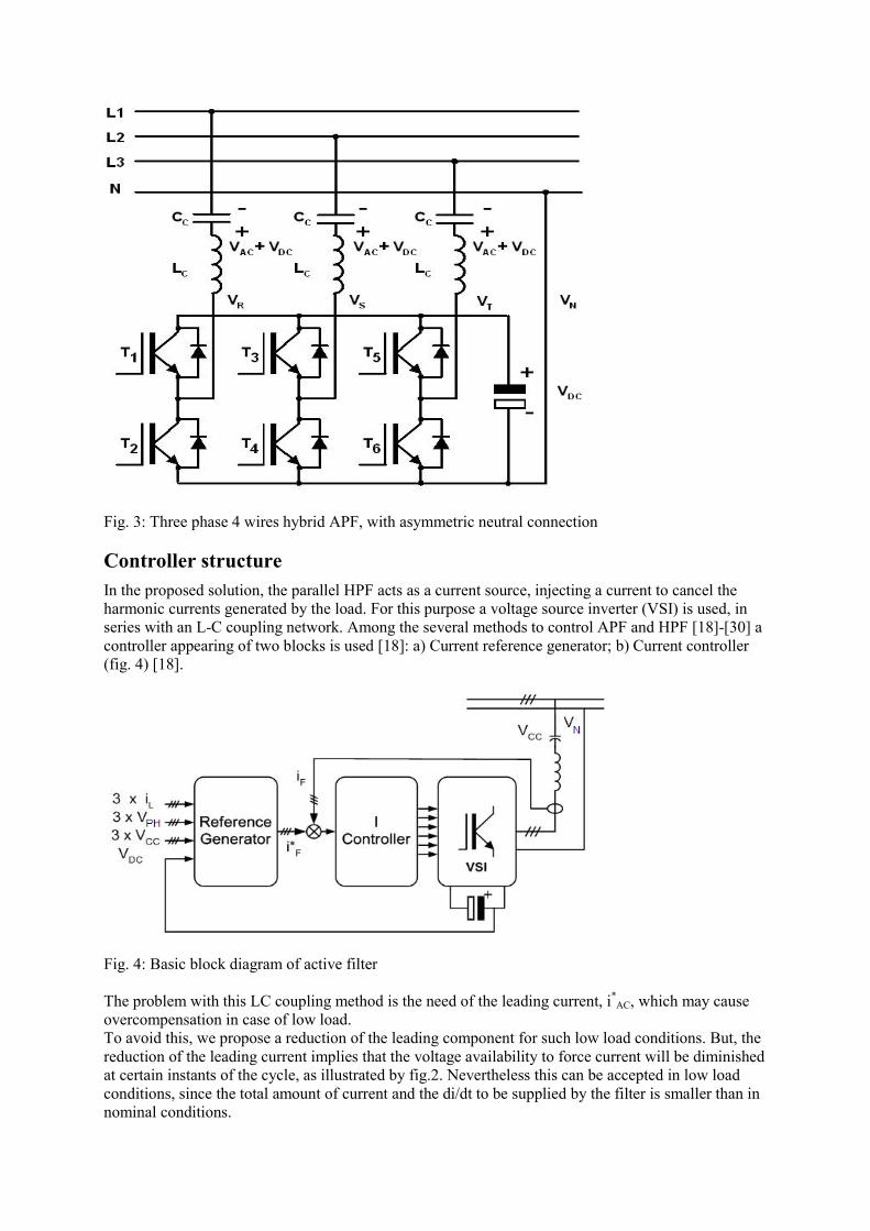
Fig. 3: Three phase 4 wires hybrid APF, with asymmetric neutral connection
Controller structure In the proposed solution, the parallel HPF acts as a current source, injecting a current to cancel the harmonic currents generated by the load. For this purpose a voltage source inverter (VSI) is used, in series with an L-C coupling network. Among the several methods to control APF and HPF [18]-[30] a controller appearing of two blocks is used [18]: a) Current reference generator; b) Current controller (fig. 4) [18].
Fig. 4: Basic block diagram of active filter The problem with this LC coupling method is the need of the leading current, i*
AC, which may cause overcompensation in case of low load. To avoid this, we propose a reduction of the leading component for such low load conditions. But, the reduction of the leading current implies that the voltage availability to force current will be diminished at certain instants of the cycle, as illustrated by fig.2. Nevertheless this can be accepted in low load conditions, since the total amount of current and the di/dt to be supplied by the filter is smaller than in nominal conditions.
The reference generator calculates the filter current, i*F, needed for the correct operation of the APF,
which consists of three terms [18], as given in (1).
*AC
*CC
*H
*F iiii ++= (1)
where: i*
H is the ripple of the load current (harmonics), to be cancelled by the APF. This current component may be obtained by subtracting the fundamental component from the total load current. Fundamental component is derived from active power, using for example, the method detailed in [4] i*
CC is an error current, to maintain the DC voltage of coupling capacitors at VDC/2. i*
AC is the necessary current to neutralize the AC mains voltage. If a total cancellation is desired, its value is given by (2): CPHPHAC KjVCjVi ⋅⋅=⋅⋅⋅= ω* (2)
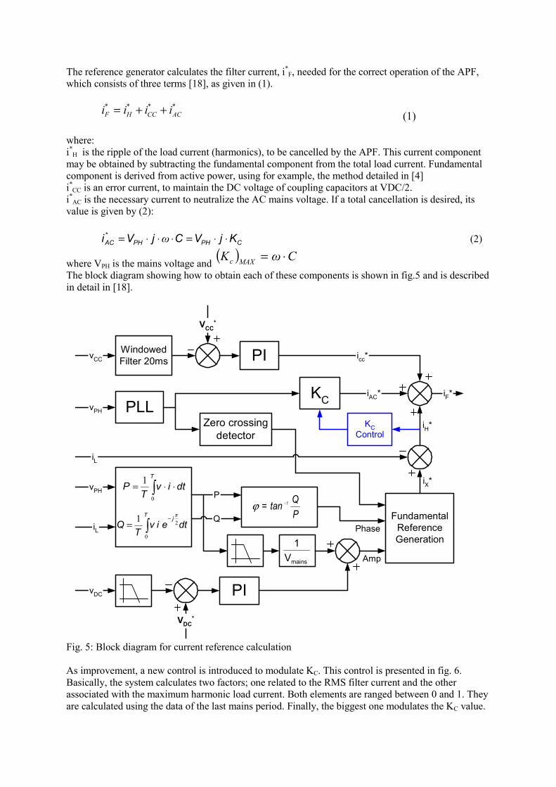
where VPH is the mains voltage and ( ) CωK MAXc ⋅= The block diagram showing how to obtain each of these components is shown in fig.5 and is described in detail in [18].
WindowedFilter 20msvCC
VCC*
PLLvPH
KCiF*
∫ ⋅⋅=T
dtivT
P0
1
dteivT
QjT2
0
1 π−
∫=
vPH
iL
P
Q
vDC
VDC*
PI
PI
mainsV1
FundamentalReferenceGeneration
Phase
Amp
icc*
iAC*
Zero crossingdetector
iL
iH*
iX*
PQtan 1-=ϕ
KCControl
Fig. 5: Block diagram for current reference calculation As improvement, a new control is introduced to modulate KC. This control is presented in fig. 6. Basically, the system calculates two factors; one related to the RMS filter current and the other associated with the maximum harmonic load current. Both elements are ranged between 0 and 1. They are calculated using the data of the last mains period. Finally, the biggest one modulates the KC value.

A minimum KC (KCmin) is guaranteed to prevent power filter malfunction that has been perceived in the first system simulations.
iH*iH*
**1−
−ii HH ii ⎟
⎟
⎠
⎞
⎜⎜
⎝
⎛
ΔΔ
÷Δ
Δ−
ti
ti
MAX ii HH**
256
MAXdtiH
id *
RMSiH*RMS
(iF*RMS)
MAX
MAX
KC MIN
0
1 KC
10 ÷
10 ÷
:
:∑−4j
jH ji *
41
Fig. 6: Block diagram of Kc control Notice that except the VDC controller; all the rest (fig. 5 and 6) must be implemented for each phase; so the system operates properly in case of unbalanced source voltages. If the mains voltage contains a large amount of harmonic components, the output of PLL can be used to calculate P and Q values.
Simulation Results In order to validate the novel structure and control systems, some simulations have been carried out, using Matlab-Simulink tools and the SimPower Systems toolbox. The load used for the test is formed of a symmetrical three phase load (I≅10A), consisting of a 6 pulse rectifier with RC load, plus a single phase rectifier between phase L3 and neutral (I≅25A). This rectifier can be switched on and off to unbalance the whole system. The actual values of simulation parameters were: the LC coupling network L=800μH and C=417μF; VDC = 600V; switching frequency 12.8 kHz. To preclude system malfunction KCmin has to be equal or greater than 0.3.
Fig. 7: Simulated three phase load and mains currents and KC evolution in a start up
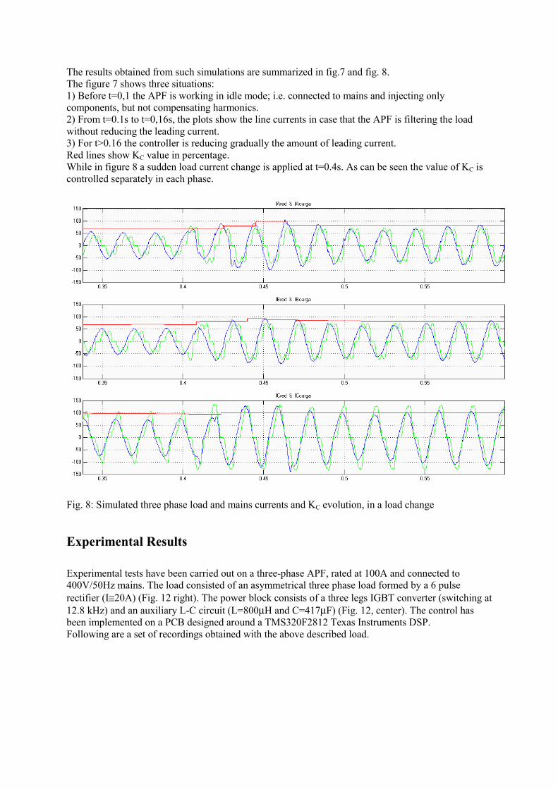
The results obtained from such simulations are summarized in fig.7 and fig. 8. The figure 7 shows three situations: 1) Before t=0,1 the APF is working in idle mode; i.e. connected to mains and injecting only components, but not compensating harmonics. 2) From t=0.1s to t=0,16s, the plots show the line currents in case that the APF is filtering the load without reducing the leading current. 3) For t>0.16 the controller is reducing gradually the amount of leading current. Red lines show KC value in percentage. While in figure 8 a sudden load current change is applied at t=0.4s. As can be seen the value of KC is controlled separately in each phase.
Fig. 8: Simulated three phase load and mains currents and KC evolution, in a load change
Experimental Results Experimental tests have been carried out on a three-phase APF, rated at 100A and connected to 400V/50Hz mains. The load consisted of an asymmetrical three phase load formed by a 6 pulse rectifier (I≅20A) (Fig. 12 right). The power block consists of a three legs IGBT converter (switching at 12.8 kHz) and an auxiliary L-C circuit (L=800μH and C=417μF) (Fig. 12, center). The control has been implemented on a PCB designed around a TMS320F2812 Texas Instruments DSP. Following are a set of recordings obtained with the above described load.
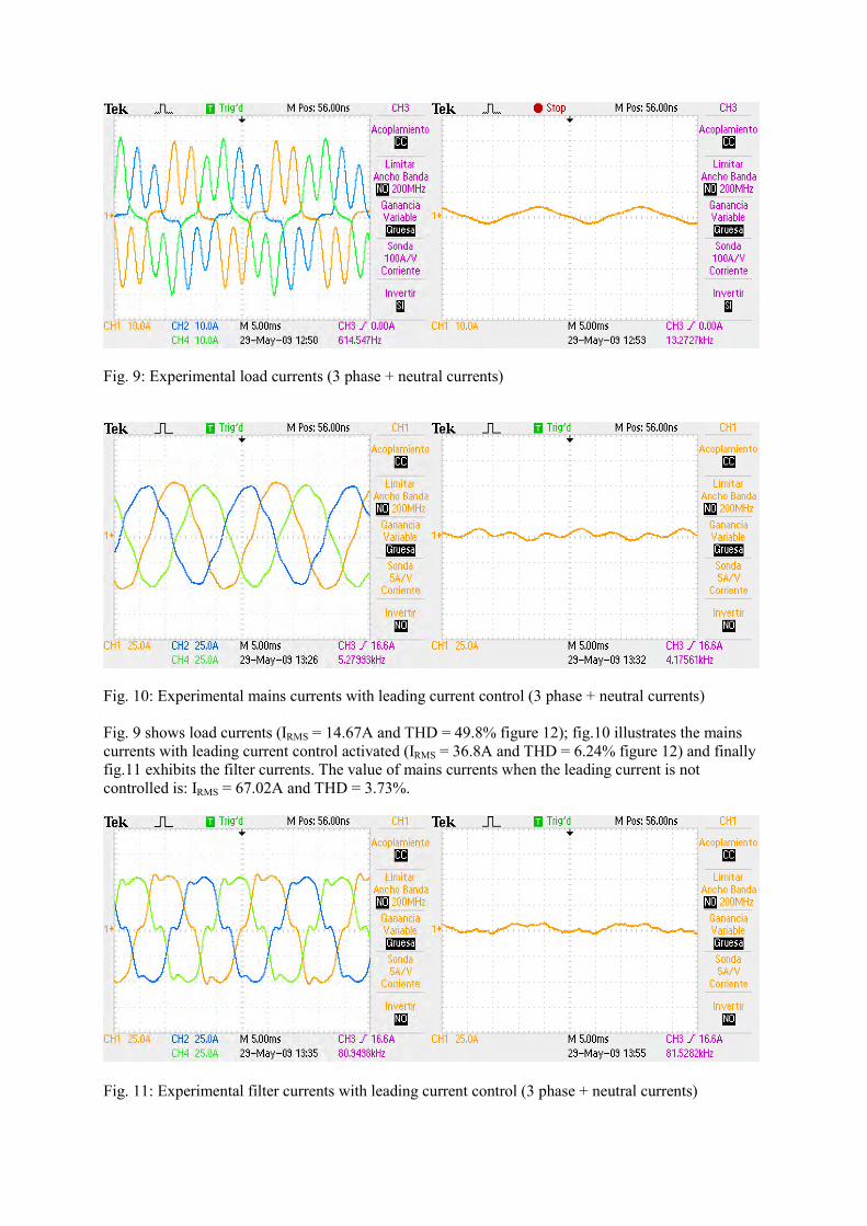
Fig. 9: Experimental load currents (3 phase + neutral currents)
Fig. 10: Experimental mains currents with leading current control (3 phase + neutral currents) Fig. 9 shows load currents (IRMS = 14.67A and THD = 49.8% figure 12); fig.10 illustrates the mains currents with leading current control activated (IRMS = 36.8A and THD = 6.24% figure 12) and finally fig.11 exhibits the filter currents. The value of mains currents when the leading current is not controlled is: IRMS = 67.02A and THD = 3.73%.
Fig. 11: Experimental filter currents with leading current control (3 phase + neutral currents)

Fig. 12: Experimental load and line currents THD with leading current control.
Fig. 13: Experimental Plant in the laboratory
Conclusion The paper presents some new techniques to improve the control of a hybrid active power filter, in order to decrease the leading current, which has been defined as the major drawback of hybrid structures. Such techniques are based on allowing a certain asymmetry in the available voltages to force di/dt in case of low load situations (below the filter rating). This allows a significant reduction of the necessary leading current still maintaining the filtering performances in terms of final THD of the line currents. The paper shows the simulation and experimental results illustrating the reduction of the total RMS currents.
References [1] Hung-Liang Chou, Chin-Chang Wu, Wen-Pin Hsu, “Power Converter of a Hybrid Power Filter¨ U.S. Patent Publication No. US2005/0207197A1, Sept., 2005. [2] Akagi H; “Active Harmonic Filters”; Proceedings of the IEEE, Vol. 93, No. 12, December 2005.

[3] F. Z. Peng, “Harmonic sources and filtering approaches,” IEEE Industry. Applications. Magazine, vol. 7, pp. 18–25, 2001. [4] B. Singh, K. Al-Haddad, and A. Chandra, “A review of active filters for power quality improvement,” IEEE Transactions on Industrial Electronics., vol. 46, no. 6, pp. 960–971, Dec. 1999. [5] J. Balcells, D. Gonzalez, M. Lamich, E. Aldabas; “Separate control of Power factor Components Based on Phase Locked Loop”, ETEP ; Vol 8, Nª 4, VDE Verlag July/August 1998 [6] Sangshin Kwak, H.A. Toliyat, "Current-source-rectifier topologies for sinusoidal supply current: theoretical studies and analyses," Trans. on Industrial Electronics, vol. 53, no. 3, pp. 984- 987, June 2006. [7] Shigenori Inoue, Toshihisa Shimizu, Keiji Wada, "Control Methods and Compensation Characteristics of a Series Active Filter for a Neutral Conductor," Trans. on Industrial Electronics, vol. 54, no. 1, pp. 433-440, Feb. 2007. [8] Akagi H, Sunt Srianthumrong, and Yasuhiro Tamai; “Comparisons in Circuit Configuration and Filtering Performance between Hybrid and Pure Shunt Active Filters” Proceedings of ISIE-2000, pp. TU26 – TU36; IEEE, Industrial Electronics Society, Choula, Mexico 2000 [9] B. Singh, V. Verma, A. Chandra and K. Al-Haddad, “Hybrid filters for power quality improvement” IEE Proceedings on Gener. Transm. Distrib., Vol. 152, No. 3, May 2005 [10] A. Nava-Segura, G. Mino-Aguilar “Four-Branches-Inverter-Based-Active-Filter for Unbalanced 3-Phase 4-Wires Electrical Distribution Systems”. Proceedings of IAS.2000. Rome, 2000. [11] Rodriguez, P.; Pindado, R.; Bergas, J.; Alternative topology for three-phase four-wires PWM converters applied to a shunt active power filter; IECON 02 . Proceedings of Industrial Electronics Society, IEEE 2002 28th Annual Conference, Volume 4, 5-8 Nov. 2002 Page(s):2939 – 2944 [12] Micah E. Ortúzar, Rodrigo E. Carmi, Juan W. Dixon, and Luis Morán; “Voltage-Source Active Power Filter Based on Multilevel Converter and Ultracapacitor DC Link” ; IEEE Transactions on Industrial Electronics, vol. 53, no. 2, pp.477- 485, April 2006 [13] A. Nakagima, J. Nishidai, and T. Shiraishi, “Development of active filter with series resonant circuit,” Proceedings of . PESC_1988 , pp. 1168–1173 , IEEE 1988 [14] H. Fujita and H. Akagi, “A practical approach to harmonic compensation in power systems: Series connection of passive and active filters,” Proceedings of IEEE-IAS Annual. Meeting 1990, pp. 1107–1112. [15] Sunt Srianthumrong, Akagi H, “A Medium-Voltage Transformerless AC/DC Power Conversion System Consisting of a Diode Rectifier and a Shunt Hybrid Filter”; IEEE Transactions on Industry Applications, Vol. 39, No. 3, May/June 2003 [16] D. Basic, V.S. Ramsden, P.K. Muttik, "Harmonic filtering of high-power 12-pulse rectifier loads with a selective hybrid filter system," Trans. on Industrial Electronics, vol.48, no.6, pp.1118-1127, Dec. 2001 [17] Sewan Choi, M. Jang, "A reduced-rating hybrid filter to suppress neutral current harmonics in three-phase four-wire systems," Trans. on Industrial Electronics, vol. 51, no. 4, pp. 927- 930, Aug. 2004. [18] M.Lamich, J. Balcells, J.Garcia, D. González , J. Gago, New Structure for Three Phase Four Wires Hybrid Active Filters; IEEE Industrial Electronics, IECON 2006 - 32nd Annual Conference , Paris, Nov. 2006 Page(s):1643 – 1648 [19] Jinn-Chang Wu; Hurng-Liahng Jou; Ya-Tsung Feng; Hsu, W.-P.; Min-Sheng Huang; Hou, W.-J. “Novel Circuit Topology for Three-Phase Active Power Filter¨, IEEE Transactions on Power Delivery, Volume 22, Issue 1, Jan. 2007 Page(s):444- 449. [20] Robert Grino, Rafael Cardoner, Ramon Costa-Castello, Enric Fossas, “Digital Repetitive Control of a Three-Phase Four-Wire Shunt Active Filter”, Trans. on Industrial Electronics, Volume: 54, no.3, pp. 1495-1503, June 2007, ISSN: 0278-0046 [21] Bhim Singh, Vishal Verma, Jitendra Solanki, "Neural Network-Based Selective Compensation of Current Quality Problems in Distribution System," Trans. on Industrial Electronics, vol. 54, no. 1, pp. 53-60, Feb. 2007. [22] Hsiung Cheng Lin, "Intelligent Neural Network-Based Fast Power System Harmonic Detection," Trans. on Industrial Electronics, vol. 54, no. 1, pp. 43-52, Feb. 2007. [23] H. Komurcugil, O. Kukrer, "A new control strategy for single-phase shunt active power filters using a Lyapunov function," Trans. on Industrial Electronics, vol. 53, no. 1, pp. 305- 312, Feb 2006. [24] Djaffar Ould Abdeslam, Patrice Wira, Jean Merckle, Damien Flieller, Yves-Andr Chapuis, "A Unified Artificial Neural Network Architecture for Active Power Filters," Trans. on Industrial Electronics, vol. 54, no. 1, pp. 61-76, Feb. 2007

[25] Etxeberria-Otadui, A. Lopez De Heredia, H. Gaztanaga, S. Bacha, M.R. Reyero, "A Single Synchronous Frame Hybrid (SSFH) Multifrequency Controller for Power Active Filters," Trans. on Industrial Electronics, vol. 53, no. 5, pp. 1640-1648, Oct. 2006. [26] Tepper, J.S., Dixon, J.W., Venegas, G., and Mor!an, L.; “A simple frequency-independent method for calculating the reactive and harmonic current in a nonlinear load’, IEEE Trans.on Ind Electronics., vol.43 , no.6 , pp. 647–654, December 1996 [27] S.-L. Lu; “Application of DFT filter bank to power frequency harmonic measurement”; IEE Proc.-Gener. Transm. Distrib., Vol. 152, No. 1, pp. 132-136, January 2005 [28] Dixon, J.W.; Contardo, J.M.; Moran, L.A.; “A fuzzy-controlled active front-end rectifier with current harmonic filtering characteristics and minimum sensing variables”, IEEE Transactions on Power Electronics, Vol. 14, No 4, pp. 724-729, July 1999 [29] John Salmon; Liping Wang; Langdon Guay, “A current controller for 1-phase PWM rectifiers using real-time internal feedback of the PWM controller signals” , Proceedings of IEEE International Symposium on Industrial Electronics, ISIE 2006, Vol. 2, Page(s):1448 – 1453; Montreal, July 2006 [30] M. Karimi-Ghartemani, M.R. Iravani and F. Katiraei; “Extraction of signals for harmonics, reactive current and network-unbalance compensation” ; IEE Proc. Transm. Distrib., Vol. 152, No. 1, pp.137-143; January 2005.